JP2008508924A - Automatic selection of receiver elements in MRI equipment - Google Patents
Automatic selection of receiver elements in MRI equipmentDownload PDFInfo
- Publication number
- JP2008508924A JP2008508924AJP2007524438AJP2007524438AJP2008508924AJP 2008508924 AJP2008508924 AJP 2008508924AJP 2007524438 AJP2007524438 AJP 2007524438AJP 2007524438 AJP2007524438 AJP 2007524438AJP 2008508924 AJP2008508924 AJP 2008508924A
- Authority
- JP
- Japan
- Prior art keywords
- region
- interest
- carrier
- coil
- magnetic resonance
- Prior art date
- Legal status (The legal status is an assumption and is not a legal conclusion. Google has not performed a legal analysis and makes no representation as to the accuracy of the status listed.)
- Pending
Links
- 238000002595magnetic resonance imagingMethods0.000claimsabstractdescription59
- 238000003384imaging methodMethods0.000claimsabstractdescription37
- 230000004044responseEffects0.000claimsabstractdescription6
- 230000005284excitationEffects0.000claimsabstractdescription4
- 238000000034methodMethods0.000claimsdescription23
- 238000004590computer programMethods0.000claimsdescription21
- 230000008569processEffects0.000claimsdescription8
- 238000012545processingMethods0.000abstractdescription8
- 230000005540biological transmissionEffects0.000abstractdescription3
- 210000003484anatomyAnatomy0.000description11
- 238000013461designMethods0.000description10
- 238000006243chemical reactionMethods0.000description5
- 238000009434installationMethods0.000description5
- 238000004458analytical methodMethods0.000description4
- 230000009466transformationEffects0.000description4
- 238000004364calculation methodMethods0.000description3
- 230000008859changeEffects0.000description3
- 210000003127kneeAnatomy0.000description3
- 230000035945sensitivityEffects0.000description2
- IUVCFHHAEHNCFT-INIZCTEOSA-N2-[(1s)-1-[4-amino-3-(3-fluoro-4-propan-2-yloxyphenyl)pyrazolo[3,4-d]pyrimidin-1-yl]ethyl]-6-fluoro-3-(3-fluorophenyl)chromen-4-oneChemical compoundC1=C(F)C(OC(C)C)=CC=C1C(C1=C(N)N=CN=C11)=NN1[C@@H](C)C1=C(C=2C=C(F)C=CC=2)C(=O)C2=CC(F)=CC=C2O1IUVCFHHAEHNCFT-INIZCTEOSA-N0.000description1
- 238000004040coloringMethods0.000description1
- 238000006073displacement reactionMethods0.000description1
- 238000005516engineering processMethods0.000description1
- 230000003993interactionEffects0.000description1
- 230000002452interceptive effectEffects0.000description1
- 238000005259measurementMethods0.000description1
- 230000003287optical effectEffects0.000description1
- 244000045947parasiteSpecies0.000description1
- 238000003908quality control methodMethods0.000description1
- 230000003252repetitive effectEffects0.000description1
- 238000010187selection methodMethods0.000description1
- 238000007794visualization techniqueMethods0.000description1
Images


Classifications
- G—PHYSICS
- G01—MEASURING; TESTING
- G01R—MEASURING ELECTRIC VARIABLES; MEASURING MAGNETIC VARIABLES
- G01R33/00—Arrangements or instruments for measuring magnetic variables
- G01R33/20—Arrangements or instruments for measuring magnetic variables involving magnetic resonance
- G01R33/28—Details of apparatus provided for in groups G01R33/44 - G01R33/64
- G01R33/32—Excitation or detection systems, e.g. using radio frequency signals
- G01R33/34—Constructional details, e.g. resonators, specially adapted to MR
- G01R33/341—Constructional details, e.g. resonators, specially adapted to MR comprising surface coils
- G01R33/3415—Constructional details, e.g. resonators, specially adapted to MR comprising surface coils comprising arrays of sub-coils, i.e. phased-array coils with flexible receiver channels
Landscapes
- Physics & Mathematics (AREA)
- Condensed Matter Physics & Semiconductors (AREA)
- General Physics & Mathematics (AREA)
- Magnetic Resonance Imaging Apparatus (AREA)
Abstract
Translated fromJapaneseDescription
Translated fromJapanese 本発明は、磁気共鳴画像化装置の画像化ボリュームに対象物が位置するとき、励起パルスに対する対象物の反応を示す信号を取得する磁気共鳴画像化装置に関する。その装置は、更に、その取得の目的のため受信機要素を自動的に選択する。その装置は:
−画像化ボリュームに対象物を配置するキャリアと;
−対象物における個別の領域を覆う複数の受信機要素とを有し、
その受信機要素が、磁気共鳴画像化装置において、確立された個別の寸法及び位置を持つ。The present invention relates to a magnetic resonance imaging apparatus that acquires a signal indicating a response of an object to an excitation pulse when the object is located in an imaging volume of the magnetic resonance imaging apparatus. The device further automatically selects a receiver element for the acquisition purpose. The equipment is:
-A carrier for placing an object in the imaging volume;
-A plurality of receiver elements covering individual areas in the object;
The receiver element has established individual dimensions and positions in the magnetic resonance imaging apparatus.
本発明は更に、磁気共鳴画像化装置において受信機要素を自動的に選択する方法に関し:
−その装置の画像化ボリューム内に、画像化される対象物を配置するキャリアを与えるステップと;
−複数の受信機要素を対象物に配置するステップとを有し、その受信機要素が、磁気共鳴画像化装置において、確立された個別の寸法及び位置を持つ。The invention further relates to a method for automatically selecting a receiver element in a magnetic resonance imaging apparatus:
Providing a carrier for placing an object to be imaged within the imaging volume of the device;
Placing a plurality of receiver elements on the object, the receiver elements having established individual dimensions and positions in the magnetic resonance imaging device.
本発明は更に、磁気共鳴画像化装置において、画像化される対象物に配置される複数の受信機要素から受信機要素を自動的に選択するコンピュータプログラムに関する。 The invention further relates to a computer program for automatically selecting a receiver element from a plurality of receiver elements arranged on an object to be imaged in a magnetic resonance imaging apparatus.
冒頭に述べられるような磁気共鳴装置の実施形態は、米国特許第6,223,065(B1)号から知られる。知られた磁気共鳴画像化装置は、その知られた磁気共鳴画像化装置の画像化ボリューム内の画像化される患者に配置されるコイルアレイ内の適切な受信コイル(receiver coil)の選択を可能にするよう構成される。コイルアレイを構成するコイルは、磁気共鳴画像化装置のアイソセンタに対する位置である、コイル要素の確立された位置に基づき、患者内の注目領域を画像化するよう選択される。この目的のため、知られた装置においては、コイルアレイが、そのコイルアレイに対する知られた位置を持つセンサを具備する。そのセンサは、例えば、傾斜場コイルにより与えられる傾斜磁気パルス(gradient magnetic pulse)に基づき、知られた磁気共鳴装置の磁場の局所値を表す信号を提供する。知られた磁気共鳴画像化装置の選択的に適用される傾斜磁場(magnetic gradient field)のセンシング(sensing:感知)を行うため、シールドされたZ軸傾斜場センサが、センサの各端に配置される。従って、センサにおける信号は、知られた磁気共鳴画像化装置のアイソセンタに対するセンサの変位に直接比例する。アレイを構成するコイル要素は、センサに対して所定の位置を持つ。その実際の位置は、センサにより与えられる位置情報から推定される。注目領域を画像化する適切なコイル要素の選択は、注目領域の位置とアレイ内のコイル要素の実際の位置との比較から決定される。 An embodiment of a magnetic resonance apparatus as described at the outset is known from US Pat. No. 6,223,065 (B1). A known magnetic resonance imaging device allows the selection of an appropriate receiver coil within a coil array that is placed on the patient to be imaged within the imaging volume of that known magnetic resonance imaging device Configured to be The coils that make up the coil array are selected to image a region of interest within the patient based on the established position of the coil element, which is the position relative to the isocenter of the magnetic resonance imaging device. For this purpose, in the known device, the coil array comprises a sensor with a known position relative to the coil array. The sensor provides a signal representing the local value of the magnetic field of a known magnetic resonance device, for example based on a gradient magnetic pulse provided by a gradient field coil. A shielded Z-axis gradient field sensor is placed at each end of the sensor to sense the selectively applied magnetic gradient field of known magnetic resonance imaging devices. The Thus, the signal at the sensor is directly proportional to the displacement of the sensor relative to the isocenter of the known magnetic resonance imaging device. The coil elements constituting the array have a predetermined position with respect to the sensor. Its actual position is estimated from the position information given by the sensor. The selection of the appropriate coil element to image the region of interest is determined from a comparison of the location of the region of interest and the actual position of the coil elements in the array.
知られた磁気共鳴画像化装置の不都合な点は、コイル選択のため、傾斜磁場から受信コイルアレイの位置を決定することを可能にする磁気共鳴画像化ステップが実行されなければならないことである。 A disadvantage of the known magnetic resonance imaging apparatus is that for coil selection, a magnetic resonance imaging step must be performed which makes it possible to determine the position of the receiving coil array from the gradient field.
本発明の目的は、受信機要素の選択が、簡単かつ信頼性の高い方法で自動的に可能とされる磁気共鳴画像化装置を提供することにある。 It is an object of the present invention to provide a magnetic resonance imaging apparatus in which the selection of receiver elements is automatically possible in a simple and reliable manner.
この目的のため、本発明による磁気共鳴画像化装置は更に:
−キャリアにおける対象物に対する基準点の位置を規定する画像化インジケータであって、上記基準点が注目領域を示す、画像化インジケータと、
−上記基準点に対する上記注目領域の位置及び寸法を決定する画像化ローカライザと、
−上記基準点の位置と、
−上記注目領域の上記位置及び寸法とから、
−上記キャリアにおける上記注目領域の追加的な位置及び追加的な寸法を確立し、
−上記キャリアにおける上記注目領域の上記追加的な位置及び上記追加的な寸法と、上記磁気共鳴画像化装置における上記受信機要素の個別の位置及び寸法とに基づき、複数の受信機要素から受信機要素を選択する制御ユニットとを有する。For this purpose, the magnetic resonance imaging device according to the invention further comprises:
An imaging indicator for defining the position of a reference point relative to the object in the carrier, wherein the reference point indicates a region of interest;
An imaging localizer that determines the position and size of the region of interest relative to the reference point;
-The position of the reference point;
-From the position and dimensions of the region of interest;
-Establishing additional locations and additional dimensions of the region of interest in the carrier;
From a plurality of receiver elements to a receiver based on the additional position and the additional dimension of the region of interest in the carrier and the individual position and dimension of the receiver element in the magnetic resonance imaging apparatus; And a control unit for selecting elements.
本発明の技術的手段は、例えば、システムインストール時又は画像化手順の前の、適切な較正(calibration)ステップの結果として、受信機要素の位置と注目領域の位置とが磁気共鳴画像化装置の共通基準座標系に対して明確に規定されるという条件の下、特に受信コイルといった適切な受信機要素の選択手順を完全に自動化することができるという見識に基づく。特に患者支持テーブルのような移動式(displaceable)キャリアのようなキャリアが、共通基準座標系の規定に対する適切な手段を提供する。特にキャリア又は磁石といった磁気共鳴画像化装置に対する受信機要素の個別の位置は、デザインにより知られると予想される。好ましくは、その基準は、基準磁石フレーム又はキャリアの基準フレームのどちらかとされる。共通構成において、受信機要素のうち特にコイルは、キャリアに付けられることができ、それと共に移動することができる。このことが、それぞれの新たなセットアップに対し磁気共鳴画像化装置における受信機要素の位置の決定を必要とすることに留意されたい。また、受信コイルの中には、例えば、フェーズドアレイ(phased-array)コイルが一例だが、磁石穴(bore)に取り付けられ、その位置を変えないものがある。この場合、斯かるコイルの個別の位置と、フェーズドアレイを構成するコイル要素の座標とを一旦確立し、アクセス可能なファイルに対応するデータを格納すれば十分である。例えば、ルックアップテーブルは、例えば磁気画像化装置において使用される異なるコイル及び異なるコイル構成といった異なる受信機要素に対応して演繹的に用意されることができる。好ましくは、ルックアップテーブルは、コイルの個別の寸法も有し、それは好ましくは、受信コイルの原点のような演繹的に確立される個別の適切な原点に対するコイル要素の個別の座標として特定される。ルックアップテーブルは、好ましくは、適切なファイルに格納され、制御ユニットによりアクセス可能である。また、例えば受信コイルといった受信機要素の個別のトポロジの演繹的な知識に感度パターン(sensitivity pattern)をマッチ(match:適合)させることにより、受信機要素の個別の位置が、適切な磁気共鳴スキャンから確立されることができる。例えば磁気穴に取り付けられる後方部分(posterior portion)のような固定的な要素と、例えばキャリアに付けられる前方部分(anterior portion)のような移動可能な要素とを受信機要素が有する場合、前方部分の位置のみが確立されなければならない。次に、画像化される予定の注目領域が、同様にキャリアに対して基準化される(referenced)。有利なことに、これは、対象物における基準点を取り除く(seed)標準的なライトバイザー(light visor:光よけ)動作により容易化される。キャリアに対するこの位置は、最新の磁気共鳴画像化装置の機能により自動的に確立される。想定される注目領域の内側にライトバイザーを配置することはありふれているが、患者又はキャリアのどこかに基準点を配置し、基準点と、想定される注目領域との間の距離を格納することも可能である。基準点に対する磁場傾斜強度(magnetic field gradient strength)と組み合わせるRFパルスの周波数オフセット及び帯域幅をセットする画像化ローカライザにより、注目領域のジオメトリが決定される。好ましくは、画像化ローカライザは、適切な画像化テンプレートに基づき、注目領域の寸法を自動的に割り当てるよう構成される。また、注目領域の寸法は、適切な調査スキャンを用いて操作者により設定されることもできる。更にまた、注目領域の寸法は、例えば画像化テンプレートにおいて演繹的にセットされることもできる。この場合、注目領域の位置及び大きさは、画像化テンプレートに対応する適切なファイルを読み出すことにより決定される。そこで、注目領域の位置及び寸法も自動的に確立されることができる。通常、これは、患者の基準フレームにおいて実行される。本発明による磁気共鳴画像化装置において、キャリアの基準フレームに対する注目領域の追加的な位置及び追加的な寸法を確立するのに制御ユニットが与えられる。こうして、注目領域及び受信機要素は、例えばシステムの基準フレームといった共通の基準フレームにおける基準となる。そして、こうして確立された注目領域の追加的な位置及び追加的な寸法と、対象物の周りの磁気共鳴画像化装置に配置される複数の受信機要素における受信コイルの確立された個別の位置及び寸法とから、制御ユニットは適切な受信機要素を選択する。 The technical means of the present invention is that the position of the receiver element and the position of the region of interest of the magnetic resonance imaging device are, for example, as a result of an appropriate calibration step during system installation or prior to the imaging procedure. Based on the insight that the selection procedure of the appropriate receiver element, in particular the receiver coil, can be fully automated under the condition that it is clearly defined with respect to a common reference coordinate system. In particular, a carrier such as a displaceable carrier such as a patient support table provides a suitable means for defining a common reference coordinate system. It is expected that the individual position of the receiver element, in particular relative to the magnetic resonance imaging device, such as a carrier or a magnet, will be known by design. Preferably, the reference is either a reference magnet frame or a carrier reference frame. In a common configuration, among the receiver elements, in particular the coil can be attached to the carrier and can move with it. Note that this requires the determination of the position of the receiver element in the magnetic resonance imager for each new setup. In addition, among the receiving coils, for example, a phased-array coil is an example, but there is a receiving coil that is attached to a magnet hole and does not change its position. In this case, it is sufficient to once establish the individual positions of such coils and the coordinates of the coil elements that make up the phased array and store the data corresponding to the accessible file. For example, look-up tables can be prepared a priori for different receiver elements such as different coils and different coil configurations used in magnetic imaging devices, for example. Preferably, the look-up table also has individual dimensions of the coil, which are preferably specified as individual coordinates of the coil element relative to an individual appropriate origin established a priori such as the origin of the receiving coil. . The lookup table is preferably stored in a suitable file and accessible by the control unit. In addition, by matching the sensitivity pattern to the a priori knowledge of the individual topology of the receiver element, e.g. the receiver coil, the individual position of the receiver element can be matched to an appropriate magnetic resonance scan. Can be established from. If the receiver element has a stationary element, e.g. a posterior portion attached to the magnetic hole, and a movable element, e.g. an anterior portion attached to the carrier, the front part Only the position of must be established. Next, the region of interest to be imaged is similarly referenced with respect to the carrier. Advantageously, this is facilitated by a standard light visor operation that seeds the reference point in the object. This position with respect to the carrier is automatically established by the function of modern magnetic resonance imaging equipment. It is common to place a light visor inside an assumed area of interest, but place a reference point somewhere on the patient or carrier and store the distance between the reference point and the assumed area of interest It is also possible. The geometry of the region of interest is determined by an imaging localizer that sets the frequency offset and bandwidth of the RF pulse combined with the magnetic field gradient strength relative to the reference point. Preferably, the imaging localizer is configured to automatically assign the size of the region of interest based on a suitable imaging template. The dimension of the region of interest can also be set by the operator using an appropriate survey scan. Furthermore, the dimensions of the region of interest can be set a priori, for example in an imaging template. In this case, the position and size of the region of interest are determined by reading an appropriate file corresponding to the imaging template. Thus, the position and size of the region of interest can also be automatically established. Typically this is performed in the patient's reference frame. In the magnetic resonance imaging device according to the invention, a control unit is provided for establishing an additional position and an additional dimension of the region of interest relative to the reference frame of the carrier. Thus, the region of interest and the receiver element serve as a reference in a common reference frame, for example a system reference frame. And the additional position and additional dimensions of the region of interest thus established and the established individual positions of the receiving coils in the plurality of receiver elements arranged in the magnetic resonance imaging device around the object and From the dimensions, the control unit selects the appropriate receiver element.
受信機要素という単語は、磁気共鳴信号の影響を受けやすいRFアンテナ、又はコイルアレイ内のコイル要素、又はヘッドコイル若しくは先端コイルのような物理的に分離した受信コイル構成のことを指すことに留意されたい。後者の場合、キャリアにおける同じ受信コイル構成の異なる位置に対してルックアップテーブルが更新される必要がないよう、受信コイル構成は、キャリア上で所定の反復的に使用される居住位置を持つことが好ましい。 Note that the term receiver element refers to an RF antenna that is sensitive to magnetic resonance signals, or a coil element in a coil array, or a physically separate receive coil configuration such as a head coil or tip coil. I want to be. In the latter case, the receive coil configuration may have a predetermined repetitive use location on the carrier so that the look-up table need not be updated for different locations of the same receive coil configuration on the carrier. preferable.
本発明の技術的な手段によれば、対象物に配置される複数の受信機要素における各受信機要素の位置は、ベクトル計算にまで減らされ、それは解き易い。好ましくは、対応する計算が、例えば注目領域の位置、特にコイル又はコイル要素といった受信機要素の感度ボリューム、及び注目領域からかなり離れたコイルでMR信号を取得することに起因する信号対ノイズ比の損失に関する対価(consideration)に対してパラメタ化される。すると、制御ユニットは、キャリアにおける注目領域の位置及び大きさが得られたイベントに対して、このパラメタ化された計算を行い、直ちに受信機要素の必要な選択を決定する。前と同じように(As follows from the foregoing)、受信機要素の適切な選択を確立するためにいずれかの実質的なユーザ対話が必要とされることもなければ、いずれかの磁気共鳴画像化が必要とされることもない。従って、磁気共鳴画像化の全体のワークフローが改善される。 According to the technical means of the present invention, the position of each receiver element in the plurality of receiver elements arranged on the object is reduced to a vector calculation, which is easy to solve. Preferably, the corresponding calculation is for example the position of the region of interest, in particular the sensitivity volume of the receiver element, such as a coil or coil element, and the signal-to-noise ratio resulting from acquiring the MR signal with a coil far away from the region of interest. It is parameterized against the loss consideration. The control unit then performs this parameterized calculation on the event for which the position and size of the region of interest on the carrier is obtained and immediately determines the required selection of receiver elements. As follows from the same, no substantial user interaction is required to establish the proper selection of receiver elements, either magnetic resonance imaging. Is never needed. Thus, the overall workflow of magnetic resonance imaging is improved.
好ましくは、本発明による磁気共鳴画像化装置において、特にキャリア又は磁石といった磁気共鳴画像化装置に対する受信機要素の位置、及び、特にコイルといった受信機要素の個別の大きさが、システムデザインにより知られ、ルックアップテーブルに格納される。磁石のアイソセンタに対する患者支持台の相対位置が、システムインストールの際に調整され、ルックアップテーブルに格納される。制御ユニットは、適切な受信機要素を選択するために、キャリアに相対的な注目領域の決定された追加的な位置及び追加的な寸法と共にルックアップテーブルからのデータを用いる。 Preferably, in the magnetic resonance imaging device according to the invention, the position of the receiver element relative to the magnetic resonance imaging device, in particular a carrier or a magnet, and the individual size of the receiver element, in particular a coil, is known from the system design. Stored in a lookup table. The relative position of the patient support relative to the magnet isocenter is adjusted during system installation and stored in a look-up table. The control unit uses the data from the lookup table along with the determined additional location and additional dimensions of the region of interest relative to the carrier to select the appropriate receiver element.
磁気共鳴画像化装置において、いくつかの関連付けられた基準フレームが存在することを理解されたい。最初に、磁石及び傾斜システムは、一般にアイソセンタと呼ばれる原点で、その共通基準フレームを持つ。通常ライトバイザーとして実現される画像化インジケータは、磁気共鳴画像化装置のデザインにより知られる位置を持ち、磁石の基準フレームで固定される。第2に、キャリアは、自身の基準フレームを持つ。その位置は、磁気共鳴装置のインストール手順の間に、磁石の基準フレームに対して調整される。その結果、測定されるキャリアの実際の位置を磁石の基準フレームに例えば適切なソフトウェアを用いて翻訳するのに単純な変換が使用されることができる。第3に、特に受信コイルといった受信機要素は、キャリアに対して、それ自身の基準フレームとその位置とを持つ。コイル要素の位置は、通常受信コイルの規定された原点に関連付けられる。幾つかのコイル装置が想定される。つまり、例えば、キャリアに存在する適切なコイル固定手段によって、キャリアに対する位置がデザインにより知られる固定されたコイル、又は、その位置が適切な機械的手段を有する自動的な位置決め手段及び/若しくは適切な無線位置決め技術を用いて確立されることができる移動式コイルである。第4に、患者は通常、磁気共鳴画像化装置を用いて画像化される予定の選択された生体構造領域に例えば関連付けられる、患者自身の基準フレームに割り当てられる。生体構造領域の位置は、ライトバイザ−動作からユーザにより選択可能である。それにより、ユーザは、患者の基準フレームを、磁石の基準フレームに関連付ける(link)。こうして、磁石の基準フレームとキャリアの基準フレームと患者の基準フレームとの間の関係は、キャリアの実際の位置に関連し、それにより、キャリアの基準フレームと受信コイルの基準フレームとの間の変換は、患者の基準フレームをコイル位置に関連させる。第5に、選択された生体構造領域内の画像化する注目領域に対する基準フレームが存在する。それは、例えば、調査スキャンに対するスキャン位置のグラフィック表現を生み出す、磁気共鳴装置の適切なユーザインタフェースにより規定される。注目領域の基準フレームは、従って、患者の基準フレームに関連付けられる。注目領域の位置及び寸法は、最初に患者の基準フレームにおいて規定される。従って、適切な受信機要素を選択するために、既存の基準フレーム間での単純な変換で十分であり、それは、簡単なベクトル解析を用いて解を求めることができる。この変換の結果は、注目領域の追加的な位置及び追加的な寸法である。それは、システムの基準フレームにおける基準であり、例えば、キャリアにより表される。磁気共鳴画像化装置の個別の基準フレームは、図5に概略的に示される。 It should be understood that there are several associated reference frames in a magnetic resonance imaging device. Initially, the magnet and tilt system have its common reference frame at the origin, commonly referred to as the isocenter. The imaging indicator, usually implemented as a light visor, has a position known by the design of the magnetic resonance imaging device and is fixed with a reference frame of the magnet. Second, the carrier has its own reference frame. Its position is adjusted with respect to the reference frame of the magnet during the installation procedure of the magnetic resonance apparatus. As a result, a simple transformation can be used to translate the actual position of the measured carrier into a magnet reference frame, for example using suitable software. Thirdly, the receiver element, in particular the receive coil, has its own reference frame and its position with respect to the carrier. The position of the coil element is usually related to the defined origin of the receiving coil. Several coil devices are envisaged. This means, for example, by means of suitable coil fixing means present in the carrier, a fixed coil whose position relative to the carrier is known by design, or an automatic positioning means whose position has appropriate mechanical means and / or suitable A mobile coil that can be established using wireless positioning technology. Fourth, the patient is typically assigned to the patient's own reference frame, eg, associated with a selected anatomical region that is to be imaged using a magnetic resonance imaging device. The position of the anatomical region can be selected by the user from the light visor operation. Thereby, the user links the patient reference frame to the magnet reference frame. Thus, the relationship between the magnet reference frame, the carrier reference frame, and the patient reference frame is related to the actual position of the carrier, thereby converting between the carrier reference frame and the receive coil reference frame. Associates the patient's reference frame with the coil position. Fifth, there is a reference frame for the region of interest to be imaged within the selected anatomical region. It is defined, for example, by a suitable user interface of the magnetic resonance apparatus that produces a graphic representation of the scan position for the survey scan. The reference frame of the region of interest is therefore associated with the patient reference frame. The location and dimensions of the region of interest are initially defined in the patient's reference frame. Thus, a simple conversion between existing reference frames is sufficient to select the appropriate receiver element, which can be solved using simple vector analysis. The result of this transformation is an additional location and additional dimensions of the region of interest. It is a reference in the reference frame of the system and is represented by, for example, a carrier. The individual reference frames of the magnetic resonance imaging apparatus are schematically shown in FIG.
本発明による磁気共鳴画像化装置の実施形態において、その装置は、受信機要素の個別の位置を自動的に確立し、制御ユニットに位置を表す信号を送信する(forward)自動位置決めモジュールを更に有する。 In an embodiment of the magnetic resonance imaging device according to the invention, the device further comprises an automatic positioning module that automatically establishes the individual positions of the receiver elements and forwards signals representing the position to the control unit. .
キャリア上の受信機要素の個別の位置を確立するのに、自動位置決めモジュールを提供することが特に有利であることがわかる。そのいくつかの実施形態が想定される。最初に、受信機要素の対応する部分と相互作用するよう、キャリアにおける受信部分を収容することが可能である。これは、機械的なロックとして実現されることができ、そのロックに接続される受信機要素のタイプを識別する適切な電子機器と共に与えられる。機械的なロックの個別の位置は、前もって決定され、ルックアップテーブルに格納されることができる。複数の受信機要素が複数の受信部分に接続されるとき、自動位置決めモジュールは直ちに個別の受信機要素が存在するキャリア上での位置を決定する。従って、適切な受信機要素の選択は、更に簡略化される。この実施形態は、受信コイル構成の個別の位置の自動的な決定に特に有利であることに留意されたい。例えば、頭部コイルと膝コイルとが患者に配置されるとき、頭部スキャンに対しては、頭部コイルが作動され、それにより膝スキャンに対しては、膝コイルが作動される。更には、コイル要素が受信部分に対して配置される座標でそれが演繹的に確立されると仮定すれば、コイル構成内のコイル要素間を同様な態様で区別することも可能である。好ましくは、識別可能なコイルを有するコイル要素のデザインが、コイルにおける固定された基準点に対する要素のすべての位置及び大きさと共にルックアップテーブルに格納される。コイルの知られたジオメトリは、コイル要素の適切なサブセットを選択するための注目領域に対するコイルの位置に関する情報と結合される。 It has proved particularly advantageous to provide an automatic positioning module for establishing individual positions of receiver elements on the carrier. Several embodiments are envisioned. Initially, it is possible to accommodate the receiving part in the carrier to interact with the corresponding part of the receiver element. This can be implemented as a mechanical lock and is provided with appropriate electronics that identify the type of receiver element connected to the lock. The individual position of the mechanical lock can be determined in advance and stored in a lookup table. When multiple receiver elements are connected to multiple receiving portions, the auto-positioning module immediately determines the position on the carrier where the individual receiver elements are present. Thus, the selection of the appropriate receiver element is further simplified. Note that this embodiment is particularly advantageous for automatic determination of the individual position of the receive coil configuration. For example, when a head coil and a knee coil are placed on a patient, the head coil is activated for a head scan and thereby the knee coil is activated for a knee scan. Furthermore, it is also possible to distinguish between coil elements in a coil configuration in a similar manner, assuming that it is established a priori at the coordinates at which the coil element is located relative to the receiving portion. Preferably, the design of a coil element having an identifiable coil is stored in a look-up table along with all positions and sizes of the element relative to a fixed reference point in the coil. The known geometry of the coil is combined with information regarding the position of the coil relative to the region of interest to select the appropriate subset of coil elements.
第2に、電子的手段を用いて、リアルタイムにキャリア上の受信機要素の位置を確立することが可能である。好ましくは、全地球測位システムのようなそれ自身は知られている位置決めシステムが使用される。好ましくは、画像化ボリュームを含む磁気共鳴画像化装置の領域をスキャンするよう小型化される。好ましくは、磁気共鳴画像化装置において、例えば、筐体の一部が、適切な数の位置決め送信機に適応する(accommodated)。それにより、受信機要素は、空間における受信機要素の存在を示す個別のビーコンに適応する。好ましくは、ビーコンは要求に応じて作動され、その結果、使用中でない受信コイルが、周囲に迷惑をかけない。ビーコンを具備する特にコイルのような受信機要素が患者に配置されるとき、位置決め送信機は、その位置及び/又はキャリア上の受信機要素を表す信号を決定する。このステップは、好ましくは、磁石穴の内部における、又はオープン磁石システムの隣接部分間でのパラサイト反射(parasite reflection)を防止するため、キャリアが画像化ボリュームから抽出されたとき実行される。こうして確立された位置は、制御ユニットに対して利用可能にされ、注目領域の画像化のための適切な受信コイルの自動的な選択のために使用される。また、この実施形態は、患者に配置される異なる専用コイル間を区別する受信コイル構成にとって特に有利である。また、コイルアレイ内での異なるコイル要素間の区別が実現可能となる。現在の位置決め技術は、特に、位置決め送信機がビーコンの近傍に配置されるとき、数センチメータ(sub-centimeter)範囲での位置決め情報を区別することを容易にすることに留意されたい。受信コイル選択のため、コイル位置の認識は、5-10 cmの精度にあれば十分であることに留意されなければならない。 Second, it is possible to establish the position of the receiver element on the carrier in real time using electronic means. Preferably, a positioning system known per se, such as a global positioning system, is used. Preferably, it is miniaturized to scan a region of the magnetic resonance imaging device that includes the imaging volume. Preferably, in a magnetic resonance imaging apparatus, for example, a portion of the housing is adapted to an appropriate number of positioning transmitters. Thereby, the receiver element adapts to an individual beacon indicating the presence of the receiver element in space. Preferably, the beacon is activated on demand so that a receiving coil not in use does not disturb the surroundings. When a receiver element, particularly a coil, comprising a beacon is placed on a patient, the positioning transmitter determines a signal representative of the position and / or the receiver element on the carrier. This step is preferably performed when the carrier is extracted from the imaging volume to prevent parasite reflection within the magnet bore or between adjacent portions of the open magnet system. The position thus established is made available to the control unit and used for automatic selection of the appropriate receiving coil for imaging the region of interest. This embodiment is also particularly advantageous for receiver coil configurations that distinguish between different dedicated coils placed on a patient. In addition, it is possible to distinguish between different coil elements in the coil array. Note that current positioning techniques facilitate distinguishing positioning information in the sub-centimeter range, particularly when positioning transmitters are placed in the vicinity of the beacon. It should be noted that for receiving coil selection, it is sufficient to recognize the coil position with an accuracy of 5-10 cm.
本発明による磁気共鳴画像化装置の追加的な実施形態において、それは更に、選択された受信機要素をユーザに対して視覚化するユーザインタフェースを有する。受信機要素の位置のフィードバックは、好ましくは、適切な受信機要素を選択するのに使用されるのと同じルックアップテーブルから受信機要素に関する適切なジオメトリ情報を用いることにより実現される。コイル選択を、その選択を確認又は拒絶することができるユーザにフィードバックすることが有利であることがわかる。こうして、自動コイル選択の信頼性及び品質制御が保証される。 In an additional embodiment of the magnetic resonance imaging apparatus according to the invention, it further comprises a user interface for visualizing the selected receiver element to the user. Feedback of the position of the receiver element is preferably achieved by using appropriate geometry information about the receiver element from the same lookup table used to select the appropriate receiver element. It turns out that it is advantageous to feed back the coil selection to a user who can confirm or reject the selection. In this way, the reliability and quality control of automatic coil selection is guaranteed.
本発明による磁気共鳴装置の更に追加的な実施形態において、ユーザインタフェースが、ユーザによる受信機要素の自動選択の調整を可能にするよう更に構成される。好ましくは、ユーザは、追加的なコイル若しくはコイル要素を選択し、及び/又は既に選択されたものを選択から外す(deselect)ことができる。この機能は、所望の画像品質を得るための完全なユーザ制御を可能にし、画像化手順のワークフローを更に改善する。好ましくは、選択されたコイル要素の結果として生じる位置が画像と共に格納される。更に好ましくは、システムは、診断画像と共に「プレゼンテーション状態」としてコイル位置の概略的な表現を格納する。ユーザは、画像化結果をレビューする際に、使用されるコイルの位置を表示することを選択することができる。 In a further additional embodiment of the magnetic resonance apparatus according to the invention, the user interface is further configured to allow the user to adjust the automatic selection of receiver elements. Preferably, the user can select additional coils or coil elements and / or deselect those already selected. This feature allows complete user control to obtain the desired image quality and further improves the imaging procedure workflow. Preferably, the resulting position of the selected coil element is stored with the image. More preferably, the system stores a schematic representation of the coil position as a “presentation state” along with the diagnostic image. The user can choose to display the position of the coil used when reviewing the imaging results.
本発明による方法は:
−キャリア上の対象物に対する基準点の位置を規定するステップであって、その基準点が注目領域を表す、ステップと、
−その基準点に対する注目領域の位置及び寸法を決定するステップと、
−基準点の位置並びに注目領域の位置及び寸法から、キャリア上の注目領域の追加的な位置及び追加的な寸法を確立するステップと、
−注目領域の追加的な位置及び追加的な寸法と、磁気共鳴画像化装置における受信機要素の個別の寸法及び位置とに基づき、複数の受信機要素から受信機要素を選択するステップとを有する。The method according to the invention is:
-Defining the position of a reference point relative to the object on the carrier, the reference point representing the region of interest;
-Determining the position and size of the region of interest relative to the reference point;
Establishing an additional position and additional dimensions of the region of interest on the carrier from the position of the reference point and the position and size of the region of interest;
-Selecting a receiver element from a plurality of receiver elements based on the additional position and additional dimensions of the region of interest and the individual dimensions and positions of the receiver elements in the magnetic resonance imaging apparatus; .
本発明の方法によれば、磁気共鳴画像化装置に収容される適切な受信機要素の信頼性の高い選択のための単純な自動化手順が提供される。本発明による方法の更に有利な実施形態が、請求項6、7に記載される。 The method of the present invention provides a simple automated procedure for reliable selection of suitable receiver elements housed in a magnetic resonance imaging apparatus. Further advantageous embodiments of the method according to the invention are described in claims 6 and 7.
本発明によるコンピュータプログラムは、プロセッサに:
−キャリアに配置される複数の受信機要素の個別の寸法及び位置を確立するステップと、
−そのキャリアにおける対象物に対する基準点の位置を規定するステップであって、その基準点が注目領域を示す、ステップと、
−基準点に対する注目領域の寸法及び位置を決定するステップと、
−基準点の位置並びに注目領域の位置及び寸法から、キャリアにおける注目領域の追加的な位置及び追加的な寸法を確立するステップと、
−注目領域の追加的な位置及び追加的な寸法と、磁気共鳴画像化装置における受信機要素の個別の寸法及び位置とに基づき、複数の受信機要素から受信機要素を選択するステップとを実行させる。A computer program according to the invention is provided on a processor:
Establishing individual dimensions and positions of a plurality of receiver elements arranged on the carrier;
-Defining the position of the reference point relative to the object in the carrier, the reference point indicating the region of interest;
-Determining the size and position of the region of interest relative to the reference point;
Establishing an additional location and additional dimensions of the region of interest on the carrier from the position of the reference point and the location and size of the region of interest;
Performing the step of selecting a receiver element from a plurality of receiver elements based on the additional position and additional dimensions of the region of interest and the individual dimensions and positions of the receiver elements in the magnetic resonance imaging apparatus; Let
本発明のこれら及び他の側面が、図面を参照してより詳細に説明される。 These and other aspects of the invention are described in more detail with reference to the drawings.
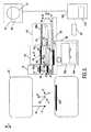
図1は、本発明による磁気共鳴画像化装置の実施形態を概略的な態様で示す。その磁気共鳴装置は、対象物7、特に画像化ボリュームVで画像化される患者を配置するキャリア8と、第1の磁石システム2と、第2の磁石システム3と、電源供給ユニット4と、RF送信機及び変調器6と、RF送信コイル(transmitter coil)5と、複数の受信機要素18、19と、送信機受信機回路9と、信号増幅器及び復調ユニット10と、処理ユニット12と、画像処理ユニット13と、モニタ14と、制御ユニット11とを有する。第1の磁石システム2は、画像化ボリュームVにおける定常磁場を生成するものとして機能する。第2の磁石システム3の様々な傾斜コイルが、X、Y、Z方向それぞれにおける傾斜を持つ追加的な磁場を生成するものとして機能する。図1に示される座標系のZ方向は、慣例により磁石システム2における定常磁場の方向に対応する。使用される測定座標系x、y、zは、図1に示されるX、Y、Z系とは独立して選択されることができる。本願の内容において、傾斜は、定常磁場に重畳され、及び3つそれぞれの直行方向における定常磁場に傾斜をもたらす一時的な磁場を意味するものとして理解されたい。 FIG. 1 shows in a schematic manner an embodiment of a magnetic resonance imaging device according to the invention. The magnetic resonance apparatus comprises an object 7, in particular a carrier 8 on which a patient to be imaged with an imaging volume V is arranged, a
傾斜コイル3は、電源供給ユニット4により給電される。RF送信コイル5は、RF磁場を生成するものとして機能し、RF送信機及び変調器6に接続される。送信コイル5は、送信機受信機回路9を介して、信号増幅器及び復調ユニット10に接続される。キャリア8上における個別の位置L1、L2に配置される受信機要素18、19は、RF磁場に対する対象物の反応を検出するよう構成される。受信機要素18、19は、磁気共鳴信号の影響を受けやすい適切なRFアンテナ、特にフェーズドアレイコイルといった受信コイル、又はコイル要素を有することができる。制御ユニット11は、RF送信機及び変調器6、電源供給ユニット4を制御し、磁気共鳴励起に対する対象物7の反応を検出するため、適切なコイル18、19を選択する。 The
適切な受信コイル18、19及び/又は受信コイル18、19の適切なコイル要素の自動的な選択を可能とするために、制御ユニット11は、キャリア8における注目領域Rの位置を計算し、受信コイルの個別の位置L1、L2を使用するよう構成される。キャリアに対する、注目する生体構造領域の位置A1又はA2は、例えば、対象物7の基準点Pを規定するよう構成されるライトバイザー20の動作を用いて自動的に決定される。それにより、その基準点は、注目する生体構造領域を示す。キャリア8に対する基準点の位置は、共通に使用される組み込みライトバイザーの機能により自動的に決定される。注目領域Rの寸法は、例えば、注目領域を規定する予め格納された画像化プロトコルを用いて、取得された調査スキャンを生体構造テンプレートにマッチさせることにより自動的に決定されるか、又は、適切なユーザインタフェース22を用いて注目領域を手動で規定することにより決定されるかのいずれかである。注目領域の手動描写(manual delineation)は、この場合、好ましくは、コンピュータマウスのような適切なグラフィックポインティングデバイス25により可能とされる。 In order to allow automatic selection of the appropriate receiving
磁気共鳴装置における幾つかの関連する基準フレームが存在することを理解されたい。最初に、磁気及び傾斜システムは、一般にアイソセンタと呼ばれる原点でその共通の基準フレームを持つ。ライトバイザーとして通常実現される画像化インジケータは、磁気共鳴装置のデザインにより知られる位置を持ち、磁石の基準フレームに固定される。第2に、キャリアは、自身の基準フレームを持ち、その位置は、磁気共鳴装置のインストール手順に間に磁石の基準フレームに対して調整される。その結果、例えば適切なソフトウェアを用いて、測定されるキャリアの実際の位置を磁石の基準フレームに翻訳するのに、単純な変換が使用されることができる。第3に、受信コイルは、キャリアに対する自身の基準フレーム及び位置を持ち、コイル要素の位置は、通常受信コイルの原点に関連付けられる。幾つかのコイル装置が想定される。例えば、キャリア上に存在する適切なコイル固定手段によって、キャリアに対する位置がデザインにより知られる固定コイル、又は適切な機械的手段を有する自動位置決め手段及び/若しくは適切な無線位置決め技術を用いてその位置が確立されることができる移動式コイルがある。第4に、患者は通常それ自身の基準フレームが割り当てられ、例えば、磁気共鳴装置を用いて画像化される選択された生体構造領域に関連付けられる。生体構造領域の位置は、ユーザにより選択可能であり、それにより、ユーザは、磁石の基準フレームに患者の基準フレームを関連付ける。従って、磁石の基準フレームとキャリアの基準フレームと患者の基準フレームとの間の関係は、キャリアの実際の位置に関連し、それにより、キャリアの基準フレームと受信コイルの基準フレームとの間の変換は、更に患者の基準フレームをコイル位置に関係させる。第5に、選択された生体構造領域内の画像化する注目領域に対する基準フレームが存在する。それは、磁気共鳴装置の適切なユーザインタフェースにより規定され、例えば調査スキャンに対するスキャン位置のグラフィック表現を生み出す。従って注目領域の基準フレームは、患者の基準フレームに関連付けられる。こうして、適切な受信コイルを選択するために、知られた基準フレーム間の簡単な変換で十分であり、それは、簡単なベクトル解析を用いて解を求めることができる(solved)。磁気共鳴装置の異なる基準フレーム間での空間的な関係が、図5を参照して説明される。 It should be understood that there are several relevant reference frames in the magnetic resonance apparatus. Initially, the magnetic and tilting system has its common reference frame at the origin, commonly called the isocenter. An imaging indicator, usually realized as a light visor, has a position known by the design of the magnetic resonance apparatus and is fixed to the reference frame of the magnet. Secondly, the carrier has its own reference frame and its position is adjusted relative to the magnet reference frame during the magnetic resonance apparatus installation procedure. As a result, a simple transformation can be used to translate the actual position of the measured carrier into a magnet reference frame, for example using suitable software. Third, the receive coil has its own reference frame and position relative to the carrier, and the position of the coil element is usually associated with the origin of the receive coil. Several coil devices are envisaged. For example, by means of suitable coil fixing means present on the carrier, the position with respect to the carrier can be determined using a fixed coil whose position is known by design, or automatic positioning means with appropriate mechanical means and / or suitable wireless positioning techniques. There are mobile coils that can be established. Fourth, the patient is usually assigned its own reference frame and is associated with a selected anatomical region that is imaged using, for example, a magnetic resonance apparatus. The position of the anatomical region is selectable by the user, thereby associating the patient reference frame with the magnet reference frame. Thus, the relationship between the magnet reference frame, the carrier reference frame, and the patient reference frame is related to the actual position of the carrier, thereby converting between the carrier reference frame and the receive coil reference frame. Further relates the patient's reference frame to the coil position. Fifth, there is a reference frame for the region of interest to be imaged within the selected anatomical region. It is defined by a suitable user interface of the magnetic resonance apparatus and produces a graphic representation of the scan position, for example for a survey scan. Accordingly, the reference frame of the region of interest is associated with the patient reference frame. Thus, a simple conversion between known reference frames is sufficient to select an appropriate receive coil, which can be solved using simple vector analysis. The spatial relationship between the different reference frames of the magnetic resonance apparatus will be described with reference to FIG.
注目領域の寸法が確立されるイベントの際、制御ユニット11は、キャリア8に対するその位置を自動的に計算する。この後、制御ユニット11は、好ましくは適切なデータベースDに格納されるルックアップテーブル23にアドレスでアクセスする(address:処理する)。そのルックアップテーブルは、磁気共鳴画像化装置における、特にキャリア上又は磁気穴内の受信コイルの個別の寸法及び受信コイル18、19の個別の位置L1、L2を有する。好ましくは、コイルアレイに対しては、ルックアップテーブル23は、個別のアレイ内の個別のコイル要素の位置を有する。その結果、コイル要素は個別に選択されることができる。また、個別のコイルの位置は、自動位置決めモジュール40を用いてリアルタイムに確立されることができる。それは、図2を参照してより詳細に説明される。この後、制御ユニット11がどの受信コイルのどの位置が注目領域の位置にマッチするかを自動的に決定し、それに従って受信コイルを選択する。全体の受信コイルがこのようにして選択されるか、又は多数のコイル要素がコイルアレイを構成することが可能である。好ましくは、その選択がユーザインタフェース上でユーザにフィードバックされる。それにより、選択されたコイルC1、C2が例えば調査スキャン上で強調表示される。選択されていないコイルもまた、異なる視覚化法、例えば空の長方形又は点線を用いて提供される。更に好ましくは、ユーザインタフェース22は、ユーザに対して自動的なコイル選択の調整を可能にするよう構成される。その調整は、例えば、コンピュータマウスといった適切なポインティングデバイス25を用いて実現されることができる。 In the event that the size of the region of interest is established, the control unit 11 automatically calculates its position with respect to the carrier 8. After this, the control unit 11 preferably accesses the look-up table 23 stored in the appropriate database D by address. The look-up table has the individual dimensions of the receiving coil and the individual positions L1, L2 of the receiving coils 18, 19 in the magnetic resonance imaging device, in particular on the carrier or in the magnetic hole. Preferably, for a coil array, the look-up table 23 has the position of individual coil elements within the individual array. As a result, the coil elements can be individually selected. Also, the position of the individual coils can be established in real time using the
図2は、本発明による自動位置決めモジュールの実施形態を概略的な態様で示す。自動位置決めモジュール40は、キャリア42上の受信コイル46、48の個別の位置を自動的に検出するよう構成され、2つの異なる方法で実現されることができる。 FIG. 2 shows in a schematic manner an embodiment of an automatic positioning module according to the invention. The
第1の実施形態において、自動位置決めモジュールは、複数の電子ソケット43a、43b、44a、44b、45a、45bを有することができる。それらは、例えば個別の電気接続を確立することを用いて、個別の受信コイル46、46a、46b、47と相互作用するよう構成される。ソケットは、異なる寸法を持つことができ、キャリア42における異なる側面方向の位置に配置されることができる。好ましくは、キャリア42における複数の電子ソケットそれぞれの位置は、知られている。個別の配線w1、w2、w3、w4、w5、w6を用いて、ソケットは論理ユニット41に接続される。それにより、論理ユニット41は、どのソケットに受信コイルが接続されるかを検出するよう構成される。この機能は、例えば、その電気インピーダンスといった個別の配線の電気パラメタの変化を測定することにより実現されることができる。好ましくは、ソケットは、それに接続される受信コイルのタイプを自動的に識別するよう構成される。これは、各ソケットw1、...w6内の特定のコネクタの提供により実現されることができる。そのコネクタは、受信コイルのコネクタの特定の一意なタイプと相互作用することが想定される。ソケットと受信コイルとの電気接続が確立されるイベントにおいて、論理ユニットは、どのソケット43a、43b、44a、44b、45a、45bに受信コイルが接続されるかを制御ユニット52に報告する。制御ユニット52は、キャリア42上のソケットの個別の位置が格納されるルックアップテーブル50を処理する。制御ユニット52が、キャリア42に対する注目領域の位置を決定するとき、図1を参照して説明されるように、利用可能な受信コイルの位置とキャリア42における注目領域の位置との間の比較に基づき、受信コイルの自動選択が行われる。また、受信コイルは、磁気穴に配置されることができる後方部分46bを有することができる。この場合、後方部分47bの位置は、デザインにより知られ、適切なルックアップテーブルに格納される。また、ルックアップテーブルは、部分46bを構成するコイル要素の個別の座標を格納する。前方部分46aの位置は、位置決めモジュールにより確立される。斯かるコイルのコイル要素は、例えば、前方部分46aと後方部分46bとにおける個別のコイル要素の座標を比較することにより、幾何学的マッチ基準に基づき選択される。こうして、前方及び後方部分がお互いに関して幾らか手動的に変位されることが可能とされる。 In the first embodiment, the automatic positioning module can have a plurality of
第2の実施形態において、自動位置決めモジュール40は、キャリア上の受信コイルの個別の位置を無線で決定するよう構成される。このため、自動位置決めモジュール40は、好ましくは、磁気共鳴装置の筐体の上、又はその適切な近傍に配置され、かつ、少なくとも磁気共鳴画像化装置の画像化ボリュームVを照射するよう構成される座標送信機t1、t2...tNのセットを有する。画像化ボリュームVに配置されると想定される受信コイル46、48は、例えば個別のビーコン47、49といった適切な追加的送信機/受信機を具備する。座標送信機t1、t2...tNは、追加的送信機/受信機と相互作用し、キャリア上のその送信機/受信機の位置を決定するよう構成される。本発明による自動位置決めモジュールの処理は、全地球測位システムと同様に機能する。しかしながら、画像化ボリュームを含む磁気共鳴装置の領域に適合するよう有限スペースにまで減らされる。好ましくは、キャリア42は、空間におけるキャリア42の位置を決定するよう構成される送信機/受信機42tを具備する。キャリア42が単一の送信機/受信機に収容される場合、キャリア42上のその位置は、演繹的に知られなければならず、制御ユニット52に利用可能とされなければならない。本発明による無線位置決めモジュールは次のように処理する。例えば送信機/受信機47に収容される受信コイル46が、キャリア42上に配置されるとき、送信機t1、t2...tNは、例えばビーコンのような送信機/受信機47からの信号を検出し、空間における受信コイル46の座標を送信する。するとその信号は、受信した信号を電気又は光学信号に変換し、制御ユニット52に対してそれを利用可能とするよう構成される無線受信機WRに無線で送信される。空間におけるキャリア42の座標は、同様な態様で決定される。キャリアにおけるビーコン42tの位置が分かっていれば、制御ユニットは、キャリア42における受信コイルの位置をこれらのデータから計算する。適切な受信コイルの選択は、キャリア42に対する注目領域の位置と、キャリア42上の受信コイルの確立された位置との間の比較から可能とされる。好ましくは、自動位置決めモジュールは要求に応じて作動可能である。その結果キャリア42上の受信コイルの位置が決定されるとき、個別の送信機が、磁気共鳴装置の周囲を乱さないようスイッチオフにされることができる。また、この場合、受信コイルは定常部分46bを持つことができる。それにより、磁気共鳴画像化装置におけるその位置と、部分46bを構成するコイル要素の個別の座標とが適切なファイルに格納される。無線位置決めユニットは、前方部分46aの位置を確立しなければならない。それは、適切なビーコン(図示省略)で与えられる。後方コイル46bと前方コイル46aとを構成するコイル要素の選択は、個別のコイル要素の座標の比較に基づき実行される。 In the second embodiment, the
例えば、適切な制御ソフトウェアを用いて決定される磁気共鳴装置の撮像視野まで、キャリアと共に動くよう構成される受信コイルを用いることも可能であることに留意されたい。この場合、磁気共鳴装置の基準フレームに対する受信コイルの原点の位置は知られており、コイル要素の適切な選択の目的のために使用される。例えば、制御ソフトウェアは、斯かる受信コイルがアイソセンタに到達したが、注目領域が完全には覆われていないことを決定するとき、患者に存在する追加的なコイルが適切に識別され、その個別の寸法及び位置が確立される。その後、その装置は、キャリア上のその確立された寸法及び位置に基づき、追加的なコイル要素を選択する処理へ進む。 It should be noted that it is possible to use a receive coil that is configured to move with the carrier, for example up to the imaging field of view of the magnetic resonance apparatus determined using suitable control software. In this case, the position of the origin of the receiving coil with respect to the reference frame of the magnetic resonance apparatus is known and used for the purpose of proper selection of the coil elements. For example, when the control software determines that such a receiver coil has reached the isocenter, but the region of interest is not completely covered, the additional coil present in the patient is properly identified and its individual Dimensions and positions are established. The device then proceeds to select additional coil elements based on their established dimensions and position on the carrier.
図3は、本発明によるユーザインタフェースの実施形態を概略的な態様で示す。ユーザインタフェース54は、好ましくは、複数の対話的フィールドを有する。最初に、コマンドフィールド55a、55b、55c及び55dが与えられる。例示を介して、コマンドフィールド55aは、適切な磁気共鳴画像化装置を処理するよう構成される。それによりスキャンパラメタが規定されるか、又は予め保存されたスキャンテンプレートからロードされる。追加的に、例えばMR取得を開始し、MR取得を停止するための制御ボタンが与えられる。制御ボタンは、制御フィールド55aで規定されるデータに基づき、磁気共鳴画像化装置を処理するよう適切なコンピュータプログラムへの適切なソフトウェアコードを用いて関連付けされる。窓55bにより概略的に表される第2の制御フィールドは、例えば、調査スキャンの適切なデータベースにアクセスするか、又は第1の制御窓55aにおいて規定されるパラメタに基づき取得されるリアルタイムデータにアクセスするよう構成される。第3の制御フィールド55cは、例えば、スキャニングプロトコルのタイプ、測定されるボクセルサイズ、PNSレベル等の動的なスキャンパラメタを規定及び/又は読み出すよう構成される。第4の制御フィールド55dは、ユーザインタフェース54の処理を制御するよう構成される。それにより、グラフィックス窓54a、54b、54cと対話する制御ボタンが提供される。例示を介してグラフィックス窓54aは、特に患者のような考慮下にある対象物の選択されたスカウト画像を視覚化するよう構成される。ユーザインタフェース54は、更に、本発明によるコンピュータプログラムと通信し、データ取得の目的のために使用される受信コイル及び/又は受信コイル要素のグラフィック表現を視覚化するよう更に構成される。こうして、ユーザインタフェース54は、選択されたコイル要素56を適切なグラフィック表現で示すよう構成される。それにより、選択されていないコイル要素57がユーザの利便性のため追加的な適切なグラフィック表現で示される。この例において、選択されたコイル要素と選択されていないコイル要素との間を区別するものとして線属性が選択されるが、影付け、色付け等他のグラフィック手段も可能である。56により示されるように、ユーザが自動コイル選択の結果に満足する場合、ユーザは、適切な制御フィールド、例えばフィールド55dにおいて適切な制御ボタンを作動する事により、データ取得へ進むことができる。他の方法では、ユーザは、グラフィック窓54aと対話することによりコイル要素の選択を変更することができる。例えば、ユーザは、幾つかのコイル要素を除外するか、又は元々は選択されていなかったコイル要素を追加することができる。このステップは、好ましくは、コンピュータマウス等のような適切なポインティングデバイスを用いて実行される。対応するMRデータ取得の結果は、好ましくは、グラフィック窓54b、54cに示される。それにより、異なる平面方向に対するスキャン結果が示される。また、グラフィック窓54b、54cの1つが、注目領域のリアルタイムに再構成された3次元画像を示すのに使用されることができる。更にまた、窓54b、54cの1つが、X線又はCTユニットといった異なる画像化モダリティを用いて取得される注目領域のマッチ画像を示すのに使用されることができる。 FIG. 3 shows in a schematic manner an embodiment of a user interface according to the present invention. The
図4は、本発明によるコンピュータプログラムの処理のブロックスキーム60を概略的な態様で示す。本発明によるコンピュータプログラムは、適切なプロセッサ(図示省略)に、磁気共鳴画像化装置のキャリアに配置される複数の受信コイルの個別の位置を確立するステップ62を実行させるよう構成される。これは、磁気共鳴画像化装置において使用されることが想定される受信コイルの個別の所定の居住位置が格納される適切なファイル(図示省略)を処理するサブステップ62aによりなされることができる。それにより、個別のコイルトポロジに関する幾何学的情報が格納され、所与のコイル構成内での個別のコイル要素の選択を可能にする。また、コンピュータプログラムは、サブステップ62bを実行することができる。そこでは、受信コイルの個別位置のリアルタイム確立が実行される。好ましくは、ステップ62bにおいて、コンピュータプログラムは、キャリアにおける受信コイルの位置を表す送信機/受信機信号の取得及び分析のため、図2を参照して論じられる自動位置決めモジュール(図示省略)を制御する。ステップ64において、コンピュータプログラムは、画像化される対象物における基準点の規定の手順を制御する。その基準点は、画像化する注目領域を示す。この目的のため、例えば、サブステップ64aにおいて、コンピュータプログラムは、磁気共鳴画像化装置のライトバイザーを制御し、キャリアにおける基準点の対応する位置を読み出す。その位置は、対象物におけるライトバイザーから放射する光ビームの衝突により決定される。ステップ66において、注目領域の寸法は、基準点を参照して確立される。このステップは、例えば、注目領域の事前格納されたテンプレートをロードするか、又は適切なユーザにより実行される注目領域の描写に対応するデータを読み出すことにより、完全に自動化された態様で実行されることができる。ステップ68において、コンピュータプログラムは、基準点の位置と注目領域の寸法とからキャリアにおける注目領域の位置を計算する。ステップ69において、コンピュータプログラムは、キャリアにおけるそのコイルの個別の位置とキャリアにおける注目領域の位置との間の比較に基づき、複数の利用可能な受信コイルから受信コイルを選択する。好ましくは、ステップ70において、コンピュータプログラムは、例としては、対象物の画像、例えば、調査スキャンにおける適切なグラフィックオブジェクトとして与えられる、選択された受信コイルを視覚化するための適切なユーザインタフェースを制御する。サブステップ72aにおいて、ユーザは、コイル及び/又はコイル要素を選択する(選択から外す)ことにより自動的に決定された選択を調整することができる。ステップ74において、コンピュータプログラムは、注目領域における対象物の応答信号の取得を可能にするため、選択された受信コイルを作動させるため適切な制御信号を送信する。 FIG. 4 shows in block form a block scheme 60 of the processing of a computer program according to the invention. The computer program according to the present invention is configured to cause a suitable processor (not shown) to perform
図5は、磁気共鳴画像化装置80における個別の基準フレームの概観を概略的な態様で示す。最初に、磁石及び傾斜システム81が、一般にアイソセンタと呼ばれる原点Oを備える共通の基準フレーム82(x1、y1、z1)を持つ。通常ライトバイザーとして実現される画像化インジケータ84が、磁気共鳴装置のデザインにより知られる位置を持ち、磁石の基準フレームにおいて固定される。画像化インジケータから放射する光ビームと、特に患者といった画像化される対象物との交差が、基準点Pを表す。第2に、キャリア83は、それ自身の基準フレーム86(x2、y2、z2)を持つ。その位置は、磁気共鳴装置のインストール手順の間に磁石81の基準フレーム82に対して調整される。その結果、測定されるキャリアの実際の位置を磁石の基準フレームに例えば適切なソフトウェア90により翻訳するのに簡単な変換が用いられることができる。例えば、そのソフトウェア90は、テーブル位置調整器(positioner)85の水平駆動85aと垂直駆動85bとに結合される電位差計の個別の信号を読み出すよう構成される。第3に、キャリアに配置される受信コイルは、それ自身の基準フレームを持つ。図5において、3つの個別の受信コイル89a、89b、87a、87b、88aが示される。そこでは、明確さのため、1つの受信コイルのみが基準フレーム87(x3、y3、z3)を備えて描かれる。また、各受信コイルは、それ自身の原点O1、O2、O3をそれぞれ持ち、それはコイルトポロジ内で任意の場所に規定されることができる。好ましくは、個別のコイルに対するコイル要素の位置は、個別の原点O1、O2、O3に対して基準化され、適切なルックアップテーブル(図示省略)に格納される。幾つかのコイル装置が想定される。例えばキャリア上に存在する適切なコイル固定手段によって、キャリアに対するその位置がデザインにより知られる固定コイル、又は適切な機械的手段を有する自動位置決め手段及び/若しくは適切な無線位置決め技術を用いてその位置が確立されることができる移動式コイルがある。また、この場合、移動可能な後方部分87bが、磁石に配置され移動可能ではない後方部分87b'により置換されることが可能である。この場合、その位置は知られており、部分87b'を構成するコイル要素の座標と共にルックアップテーブルに格納される。斯かるコイルトポロジに対して、共働部分87aの位置が確立されることになる。その位置に関して、適切な幾何学的マッチ基準に基づき個別のコイル要素が選択される。第4に、患者は通常、それ自身の基準フレーム88(x4、y4、z4)が割り当てられ、例えば、磁気共鳴画像化装置を用いて、画像化されることが想定される選択された生体構造領域A1、A2又はA3に関連付けられる。患者が磁気共鳴画像化装置の画像化ボリューム(図示省略)に挿入されるとき、生体構造領域の位置は、ライトバイザー動作に基づきユーザにより選択可能である。それにより、ユーザは、患者の基準フレーム88を磁石81の基準フレーム82に関連付ける。こうして、磁石82の基準フレームと、キャリア86の基準フレームと、患者88の基準フレームとの間の関係は、キャリア83の実際の位置に関連する。それにより、キャリア86の基準フレームと、受信コイル87の基準フレームとの間の変換は、更に患者の基準フレーム88をコイル位置へ関連させる。第5に、例えばA1といった選択された生体構造領域内の画像化する注目領域Rのための基準フレーム89(x5、y5、z5)が存在する。好ましくは、注目領域R、98が、磁気共鳴装置の適切なユーザインタフェース95により規定され、例えば調査スキャン97に対するスキャン位置98のグラフィック表現を生み出す。注目領域89の基準フレームは、従って、患者の基準フレーム88に関連付けられる。こうして、適切な受信コイルを選択するために、簡単なベクトル解析により解を求めることができる知られた基準フレーム間の単純な変換で十分である。この処理は、制御ユニット100により実行され、それは、好ましくは、図4を参照して説明されるコンピュータプログラム102により処理される。 FIG. 5 shows an overview of the individual reference frames in the magnetic
Claims (10)
Translated fromJapanese−前記画像化ボリュームに前記対象物を配置するよう構成されるキャリアと、
−前記対象物における個別の領域を覆う複数の受信機要素であって、前記磁気共鳴画像化装置において確立された個別の寸法及び位置を持つ受信機要素とを有し、
前記磁気共鳴画像化装置が、
−前記キャリアにおける前記対象物に対する基準点の位置を規定する画像化インジケータであって、前記基準点が注目領域を示す画像化インジケータと、
−前記基準点に対する前記注目領域の位置及び寸法を決定する画像化ローカライザと、
−前記基準点の前記位置並びに前記注目領域の前記位置及び寸法から、前記キャリアにおける前記注目領域の追加的な位置及び追加的な寸法を確立し、前記注目領域の前記追加的な位置及び前記追加的な寸法並びに前記磁気共鳴画像化装置における前記受信機要素の前記個別の寸法及び位置に基づき、前記複数の受信機要素から受信機要素を選択する制御ユニットとを更に有する、磁気共鳴画像化装置。A magnetic resonance imaging apparatus for acquiring a signal representative of a response of the object to an excitation pulse when the object is placed in an imaging volume, the apparatus further comprising automatically receiving a receiver element for the acquisition And the device is configured to select
A carrier configured to place the object in the imaging volume;
A plurality of receiver elements covering individual areas in the object, the receiver elements having individual dimensions and positions established in the magnetic resonance imaging device;
The magnetic resonance imaging apparatus comprises:
An imaging indicator for defining a position of a reference point relative to the object in the carrier, wherein the reference point indicates a region of interest;
An imaging localizer that determines the position and size of the region of interest relative to the reference point;
-From the position of the reference point and the position and size of the region of interest, an additional position and an additional size of the region of interest in the carrier are established, the additional position and the addition of the region of interest And a control unit for selecting a receiver element from the plurality of receiver elements based on a typical size and the individual dimensions and positions of the receiver elements in the magnetic resonance imager. .
−前記装置の画像化ボリュームに画像化される対象物を配置するキャリアを与えるステップと、
−複数の受信機要素を前記対象物に配置するステップであって、前記受信機要素が前記磁気共鳴画像化装置において確立された個別の寸法及び位置を持つ、ステップと、
−前記キャリアにおける前記対象物に対する基準点の位置を規定するステップであって、前記基準点が注目領域を示す、ステップと、
−前記基準点に対する前記注目領域の位置及び寸法を決定するステップと、
−前記基準点の前記位置並びに前記注目領域の前記位置及び寸法から、前記キャリアにおける前記注目領域の追加的な位置及び追加的な寸法を確立するステップと、
−前記注目領域の前記追加的な位置及び前記追加的な寸法並びに前記磁気共鳴画像化装置における前記受信機要素の前記個別の寸法及び位置に基づき、前記複数の受信機要素から受信機要素を選択するステップとを有する、方法。In a method for automatically selecting a receiver element in a magnetic resonance imaging apparatus,
Providing a carrier for placing an object to be imaged in the imaging volume of the device;
Placing a plurality of receiver elements on the object, the receiver elements having individual dimensions and positions established in the magnetic resonance imaging device;
-Defining the position of a reference point relative to the object in the carrier, the reference point indicating a region of interest;
Determining the position and size of the region of interest relative to the reference point;
-Establishing an additional position and an additional dimension of the region of interest on the carrier from the position of the reference point and the position and size of the region of interest;
-Selecting a receiver element from the plurality of receiver elements based on the additional position and the additional dimension of the region of interest and the individual dimension and position of the receiver element in the magnetic resonance imaging apparatus; And a step comprising:
−選択された受信機要素をユーザに対して視覚化するステップと、
−前記受信機要素の前記自動選択の前記ユーザによる調整を可能にするステップとを更に有する、請求項5又は6に記載の方法。The method comprises
-Visualizing selected receiver elements to a user;
The method according to claim 5 or 6, further comprising the step of allowing the user to adjust the automatic selection of the receiver element.
−前記磁気共鳴画像化装置に配置される前記複数の受信機要素の個別の寸法及び位置を確立するステップと、
−キャリアにおける前記対象物に対する基準点の位置を規定するステップであって、前記基準点が注目領域を示す、ステップと、
−前記基準点に対する前記注目領域の位置及び寸法を決定するステップと、
−前記基準点の前記位置並びに前記注目領域の前記位置及び寸法から、前記キャリアにおける前記注目領域の追加的な位置及び追加的な寸法を確立するステップと、
−前記注目領域の前記追加的な位置及び追加的な寸法並びに前記磁気共鳴画像化装置における前記受信機要素の前記個別の寸法及び位置に基づき、前記複数の受信機要素から受信機要素を選択するステップとを実行させる、コンピュータプログラム。A computer program for automatically selecting a receiver element from a plurality of receiver elements arranged on an object to be imaged in a magnetic resonance imaging apparatus, the computer program being stored in a processor,
-Establishing individual dimensions and positions of the plurality of receiver elements arranged in the magnetic resonance imaging device;
-Defining the position of a reference point relative to the object in a carrier, the reference point indicating a region of interest;
-Determining the position and size of the region of interest relative to the reference point;
-Establishing an additional position and an additional dimension of the region of interest on the carrier from the position of the reference point and the position and size of the region of interest;
-Selecting a receiver element from the plurality of receiver elements based on the additional position and additional dimensions of the region of interest and the individual dimensions and positions of the receiver elements in the magnetic resonance imaging apparatus; A computer program for executing steps.
Applications Claiming Priority (2)
| Application Number | Priority Date | Filing Date | Title |
|---|---|---|---|
| EP04103767 | 2004-08-05 | ||
| PCT/IB2005/052458WO2006016292A1 (en) | 2004-08-05 | 2005-07-21 | Automatic selection of a receiver element in an mri apparatus |
Publications (1)
| Publication Number | Publication Date |
|---|---|
| JP2008508924Atrue JP2008508924A (en) | 2008-03-27 |
Family
ID=35115902
Family Applications (1)
| Application Number | Title | Priority Date | Filing Date |
|---|---|---|---|
| JP2007524438APendingJP2008508924A (en) | 2004-08-05 | 2005-07-21 | Automatic selection of receiver elements in MRI equipment |
Country Status (5)
| Country | Link |
|---|---|
| US (1) | US7714576B2 (en) |
| EP (1) | EP1779129A1 (en) |
| JP (1) | JP2008508924A (en) |
| CN (1) | CN1993627B (en) |
| WO (1) | WO2006016292A1 (en) |
Cited By (2)
| Publication number | Priority date | Publication date | Assignee | Title |
|---|---|---|---|---|
| WO2013039313A1 (en)* | 2011-09-15 | 2013-03-21 | Samsung Electronics Co., Ltd. | Method of controlling an mri system and an apparatus therefor |
| JP2016101202A (en)* | 2014-11-27 | 2016-06-02 | 株式会社東芝 | Magnetic resonance imaging apparatus |
Families Citing this family (12)
| Publication number | Priority date | Publication date | Assignee | Title |
|---|---|---|---|---|
| US7508214B2 (en) | 2007-05-21 | 2009-03-24 | Medrad, Inc. | Transmit-mode phased array coils for reduced SAR and artifact issues |
| JP5053725B2 (en)* | 2007-06-25 | 2012-10-17 | 株式会社日立メディコ | Magnetic resonance imaging system |
| DE102007058682B4 (en)* | 2007-12-06 | 2018-02-08 | Siemens Healthcare Gmbh | Method and device for automatic determination of slice positions in an MR examination |
| US8085043B2 (en)* | 2009-04-03 | 2011-12-27 | Siemens Aktiengesellschaft | Method for image data acquisition with a magnetic resonance device |
| US9983281B2 (en)* | 2012-07-23 | 2018-05-29 | Toshiba Medical Systems Corporation | Magnetic resonance imaging apparatus, bed device and RF coil device |
| KR101435878B1 (en)* | 2012-12-06 | 2014-09-01 | 삼성전자주식회사 | The method and apparatus for acquiring a image in a magnetic resonance imaging system |
| KR101463420B1 (en)* | 2013-01-04 | 2014-11-19 | 삼성전자주식회사 | Method for imaging magnetic resonance image and appratus using the same thereof |
| JP6498431B2 (en)* | 2014-03-07 | 2019-04-10 | キヤノンメディカルシステムズ株式会社 | Magnetic resonance imaging apparatus and RF coil |
| JP6334983B2 (en)* | 2014-03-26 | 2018-05-30 | ジーイー・メディカル・システムズ・グローバル・テクノロジー・カンパニー・エルエルシー | Ultrasonic diagnostic apparatus and system |
| CN107479014B (en)* | 2016-06-03 | 2020-09-29 | 西门子(深圳)磁共振有限公司 | Method and device for selecting magnetic resonance coil |
| WO2019196082A1 (en)* | 2018-04-13 | 2019-10-17 | 丁炎 | Unilateral nuclear magnetic resonance for enterprises |
| DE102019207492B3 (en)* | 2019-05-22 | 2020-09-03 | Siemens Healthcare Gmbh | Coil device for a magnetic resonance system and a magnetic resonance system |
Citations (2)
| Publication number | Priority date | Publication date | Assignee | Title |
|---|---|---|---|---|
| JPH04307032A (en)* | 1990-11-21 | 1992-10-29 | Picker Internatl Inc | Magnetic resonance image pickup apparatus and method |
| JPH10290793A (en)* | 1997-04-18 | 1998-11-04 | Ge Yokogawa Medical Syst Ltd | Method and device for picking up magnetic resonant image |
Family Cites Families (11)
| Publication number | Priority date | Publication date | Assignee | Title |
|---|---|---|---|---|
| US4629989A (en) | 1983-11-10 | 1986-12-16 | General Electric Company | Patient alignment system for NMR studies |
| US5551430A (en) | 1994-08-05 | 1996-09-03 | Picker International, Inc. | RF coil identification and testing interface for NMR systems |
| US5584293A (en)* | 1995-08-16 | 1996-12-17 | General Electric Company | Time-line imaging-plane prescription for MRI |
| US6223065B1 (en)* | 1998-04-15 | 2001-04-24 | Medrad, Inc. | Automatic coil element selection in large MRI coil arrays |
| US6134465A (en)* | 1998-06-12 | 2000-10-17 | General Electric Company | Method for reducing artifacts in MR image acquired with phased array surface coil |
| DE19904537C1 (en)* | 1999-02-04 | 2000-09-07 | Siemens Ag | Method of operating diagnostic magnetic resonance apparatus with several local antennae |
| US6946836B2 (en) | 2000-04-25 | 2005-09-20 | Kabushiki Kaisha Toshiba | Magnetic resonance imaging involving movement of patient's couch |
| US6724923B2 (en) | 2001-04-13 | 2004-04-20 | Ge Medical Systems Global Technology Co., Llc | Automatic coil selection of multi-receiver MR data using fast prescan data analysis |
| US6492814B1 (en)* | 2001-12-21 | 2002-12-10 | General Electric Company | Self localizing receive coils for MR |
| DE10207736B4 (en)* | 2002-02-22 | 2007-07-19 | Siemens Ag | Method for determining the position of a local antenna |
| JP2006175058A (en)* | 2004-12-22 | 2006-07-06 | Ge Medical Systems Global Technology Co Llc | Coil element selecting method and magnetic resonance imaging apparatus |
- 2005
- 2005-07-21JPJP2007524438Apatent/JP2008508924A/enactivePending
- 2005-07-21USUS11/573,019patent/US7714576B2/ennot_activeExpired - Fee Related
- 2005-07-21EPEP05772339Apatent/EP1779129A1/ennot_activeWithdrawn
- 2005-07-21WOPCT/IB2005/052458patent/WO2006016292A1/enactiveApplication Filing
- 2005-07-21CNCN2005800263824Apatent/CN1993627B/ennot_activeExpired - Fee Related
Patent Citations (2)
| Publication number | Priority date | Publication date | Assignee | Title |
|---|---|---|---|---|
| JPH04307032A (en)* | 1990-11-21 | 1992-10-29 | Picker Internatl Inc | Magnetic resonance image pickup apparatus and method |
| JPH10290793A (en)* | 1997-04-18 | 1998-11-04 | Ge Yokogawa Medical Syst Ltd | Method and device for picking up magnetic resonant image |
Cited By (5)
| Publication number | Priority date | Publication date | Assignee | Title |
|---|---|---|---|---|
| WO2013039313A1 (en)* | 2011-09-15 | 2013-03-21 | Samsung Electronics Co., Ltd. | Method of controlling an mri system and an apparatus therefor |
| US9229075B2 (en) | 2011-09-15 | 2016-01-05 | Samsung Electronics Co., Ltd. | Method of controlling an MRI system and an apparatus therefor |
| JP2016101202A (en)* | 2014-11-27 | 2016-06-02 | 株式会社東芝 | Magnetic resonance imaging apparatus |
| US10295625B2 (en) | 2014-11-27 | 2019-05-21 | Toshiba Medical Systems Corporation | Magnetic resonance imaging apparatus |
| US10670674B2 (en) | 2014-11-27 | 2020-06-02 | Canon Medical Systems Corporation | Magnetic resonance imaging apparatus |
Also Published As
| Publication number | Publication date |
|---|---|
| US7714576B2 (en) | 2010-05-11 |
| US20080303519A1 (en) | 2008-12-11 |
| EP1779129A1 (en) | 2007-05-02 |
| CN1993627B (en) | 2010-05-05 |
| WO2006016292A1 (en) | 2006-02-16 |
| CN1993627A (en) | 2007-07-04 |
Similar Documents
| Publication | Publication Date | Title |
|---|---|---|
| JP4070457B2 (en) | Apparatus and method for acquiring partial images as needed | |
| CN115113116B (en) | Method and system for coil selection in magnetic resonance imaging | |
| US7218109B2 (en) | Method and control device for operating a magnetic resonance tomography apparatus to select appropriate local coils | |
| CN104394764B (en) | The private subscribers interface intervened between tissue for MR guiding | |
| JP2008508924A (en) | Automatic selection of receiver elements in MRI equipment | |
| US7598737B2 (en) | Method and control device for determination of the position of a local coil in a magnetic resonance apparatus | |
| US20170311841A1 (en) | Magnetic resonance apparatus and operating method therefor | |
| US6542770B2 (en) | Method of determining the position of a medical instrument | |
| US20070276220A1 (en) | All in one plan scan imaging for optimization of acquisition parameters | |
| US6828787B2 (en) | Method for magnetic resonance imaging with automatic adaptation of the measuring field | |
| US20100060284A1 (en) | Magnetic resonance imaging apparatus and control method of magnetic resonance imaging apparatus | |
| US6794872B2 (en) | Method for determining the position of a local antenna in an MR system | |
| US20190029559A1 (en) | Method for a direct positioning of a region of interest of a patient inside a scanner of a magnetic resonance imaging apparatus | |
| JP5819300B2 (en) | Medical image imaging apparatus and imaging slice determination method | |
| CN101268941B (en) | Magnetic resonance method and apparatus for automatically determining objects that attenuate penetrating radiation | |
| JPH04307032A (en) | Magnetic resonance image pickup apparatus and method | |
| EP3719520B1 (en) | Optical camera for relative positioning of a patient and phased-array coils and for patient position monitoring | |
| JP2019141602A (en) | Magnetic resonance imaging device and method for identifying position of rf coil | |
| US7141976B2 (en) | Method and control device for determining the position of a local coil on a patient table of a magnetic resonance scanner | |
| KR20160087774A (en) | Method for specifying a position of a patient with respect to an isocenter of a medical imaging device | |
| KR20170064297A (en) | Medical image apparatus, and control method thereof | |
| US20160154074A1 (en) | Magnetic resonance imaging apparatus | |
| KR101754597B1 (en) | Automatic hf shim configuration for coils | |
| US20220192759A1 (en) | Navigation unit and method | |
| CN103519812A (en) | Magnetic resonance apparatus and program |
Legal Events
| Date | Code | Title | Description |
|---|---|---|---|
| A621 | Written request for application examination | Free format text:JAPANESE INTERMEDIATE CODE: A621 Effective date:20080718 | |
| A977 | Report on retrieval | Free format text:JAPANESE INTERMEDIATE CODE: A971007 Effective date:20110819 | |
| A131 | Notification of reasons for refusal | Free format text:JAPANESE INTERMEDIATE CODE: A131 Effective date:20110830 | |
| A02 | Decision of refusal | Free format text:JAPANESE INTERMEDIATE CODE: A02 Effective date:20120207 |