JP2008506447A - Material delivery system - Google Patents
Material delivery systemDownload PDFInfo
- Publication number
- JP2008506447A JP2008506447AJP2007520972AJP2007520972AJP2008506447AJP 2008506447 AJP2008506447 AJP 2008506447AJP 2007520972 AJP2007520972 AJP 2007520972AJP 2007520972 AJP2007520972 AJP 2007520972AJP 2008506447 AJP2008506447 AJP 2008506447A
- Authority
- JP
- Japan
- Prior art keywords
- balloon
- optionally
- exemplary embodiment
- pressure
- fluid
- Prior art date
- Legal status (The legal status is an assumption and is not a legal conclusion. Google has not performed a legal analysis and makes no representation as to the accuracy of the status listed.)
- Pending
Links
Images


Classifications
- A—HUMAN NECESSITIES
- A61—MEDICAL OR VETERINARY SCIENCE; HYGIENE
- A61M—DEVICES FOR INTRODUCING MEDIA INTO, OR ONTO, THE BODY; DEVICES FOR TRANSDUCING BODY MEDIA OR FOR TAKING MEDIA FROM THE BODY; DEVICES FOR PRODUCING OR ENDING SLEEP OR STUPOR
- A61M25/00—Catheters; Hollow probes
- A61M25/10—Balloon catheters
- A—HUMAN NECESSITIES
- A61—MEDICAL OR VETERINARY SCIENCE; HYGIENE
- A61F—FILTERS IMPLANTABLE INTO BLOOD VESSELS; PROSTHESES; DEVICES PROVIDING PATENCY TO, OR PREVENTING COLLAPSING OF, TUBULAR STRUCTURES OF THE BODY, e.g. STENTS; ORTHOPAEDIC, NURSING OR CONTRACEPTIVE DEVICES; FOMENTATION; TREATMENT OR PROTECTION OF EYES OR EARS; BANDAGES, DRESSINGS OR ABSORBENT PADS; FIRST-AID KITS
- A61F2/00—Filters implantable into blood vessels; Prostheses, i.e. artificial substitutes or replacements for parts of the body; Appliances for connecting them with the body; Devices providing patency to, or preventing collapsing of, tubular structures of the body, e.g. stents
- A61F2/95—Instruments specially adapted for placement or removal of stents or stent-grafts
- A61F2/958—Inflatable balloons for placing stents or stent-grafts
- A—HUMAN NECESSITIES
- A61—MEDICAL OR VETERINARY SCIENCE; HYGIENE
- A61M—DEVICES FOR INTRODUCING MEDIA INTO, OR ONTO, THE BODY; DEVICES FOR TRANSDUCING BODY MEDIA OR FOR TAKING MEDIA FROM THE BODY; DEVICES FOR PRODUCING OR ENDING SLEEP OR STUPOR
- A61M25/00—Catheters; Hollow probes
- A61M25/10—Balloon catheters
- A61M25/1027—Making of balloon catheters
- A—HUMAN NECESSITIES
- A61—MEDICAL OR VETERINARY SCIENCE; HYGIENE
- A61B—DIAGNOSIS; SURGERY; IDENTIFICATION
- A61B18/00—Surgical instruments, devices or methods for transferring non-mechanical forms of energy to or from the body
- A61B2018/00005—Cooling or heating of the probe or tissue immediately surrounding the probe
- A61B2018/00011—Cooling or heating of the probe or tissue immediately surrounding the probe with fluids
- A61B2018/00023—Cooling or heating of the probe or tissue immediately surrounding the probe with fluids closed, i.e. without wound contact by the fluid
- A—HUMAN NECESSITIES
- A61—MEDICAL OR VETERINARY SCIENCE; HYGIENE
- A61B—DIAGNOSIS; SURGERY; IDENTIFICATION
- A61B18/00—Surgical instruments, devices or methods for transferring non-mechanical forms of energy to or from the body
- A61B2018/00005—Cooling or heating of the probe or tissue immediately surrounding the probe
- A61B2018/00011—Cooling or heating of the probe or tissue immediately surrounding the probe with fluids
- A61B2018/00029—Cooling or heating of the probe or tissue immediately surrounding the probe with fluids open
- A—HUMAN NECESSITIES
- A61—MEDICAL OR VETERINARY SCIENCE; HYGIENE
- A61B—DIAGNOSIS; SURGERY; IDENTIFICATION
- A61B18/00—Surgical instruments, devices or methods for transferring non-mechanical forms of energy to or from the body
- A61B2018/00053—Mechanical features of the instrument of device
- A61B2018/00214—Expandable means emitting energy, e.g. by elements carried thereon
- A61B2018/0022—Balloons
- A61B2018/00238—Balloons porous
- A—HUMAN NECESSITIES
- A61—MEDICAL OR VETERINARY SCIENCE; HYGIENE
- A61B—DIAGNOSIS; SURGERY; IDENTIFICATION
- A61B18/00—Surgical instruments, devices or methods for transferring non-mechanical forms of energy to or from the body
- A61B2018/00315—Surgical instruments, devices or methods for transferring non-mechanical forms of energy to or from the body for treatment of particular body parts
- A61B2018/00345—Vascular system
- A—HUMAN NECESSITIES
- A61—MEDICAL OR VETERINARY SCIENCE; HYGIENE
- A61B—DIAGNOSIS; SURGERY; IDENTIFICATION
- A61B18/00—Surgical instruments, devices or methods for transferring non-mechanical forms of energy to or from the body
- A61B2018/00636—Sensing and controlling the application of energy
- A61B2018/00642—Sensing and controlling the application of energy with feedback, i.e. closed loop control
- A—HUMAN NECESSITIES
- A61—MEDICAL OR VETERINARY SCIENCE; HYGIENE
- A61B—DIAGNOSIS; SURGERY; IDENTIFICATION
- A61B18/00—Surgical instruments, devices or methods for transferring non-mechanical forms of energy to or from the body
- A61B2018/00636—Sensing and controlling the application of energy
- A61B2018/0066—Sensing and controlling the application of energy without feedback, i.e. open loop control
- A—HUMAN NECESSITIES
- A61—MEDICAL OR VETERINARY SCIENCE; HYGIENE
- A61B—DIAGNOSIS; SURGERY; IDENTIFICATION
- A61B18/00—Surgical instruments, devices or methods for transferring non-mechanical forms of energy to or from the body
- A61B2018/00636—Sensing and controlling the application of energy
- A61B2018/00666—Sensing and controlling the application of energy using a threshold value
- A61B2018/00672—Sensing and controlling the application of energy using a threshold value lower
- A—HUMAN NECESSITIES
- A61—MEDICAL OR VETERINARY SCIENCE; HYGIENE
- A61B—DIAGNOSIS; SURGERY; IDENTIFICATION
- A61B18/00—Surgical instruments, devices or methods for transferring non-mechanical forms of energy to or from the body
- A61B2018/00636—Sensing and controlling the application of energy
- A61B2018/00666—Sensing and controlling the application of energy using a threshold value
- A61B2018/00678—Sensing and controlling the application of energy using a threshold value upper
- A—HUMAN NECESSITIES
- A61—MEDICAL OR VETERINARY SCIENCE; HYGIENE
- A61B—DIAGNOSIS; SURGERY; IDENTIFICATION
- A61B18/00—Surgical instruments, devices or methods for transferring non-mechanical forms of energy to or from the body
- A61B2018/00636—Sensing and controlling the application of energy
- A61B2018/00696—Controlled or regulated parameters
- A61B2018/00702—Power or energy
- A61B2018/00708—Power or energy switching the power on or off
- A—HUMAN NECESSITIES
- A61—MEDICAL OR VETERINARY SCIENCE; HYGIENE
- A61B—DIAGNOSIS; SURGERY; IDENTIFICATION
- A61B18/00—Surgical instruments, devices or methods for transferring non-mechanical forms of energy to or from the body
- A61B2018/00636—Sensing and controlling the application of energy
- A61B2018/00696—Controlled or regulated parameters
- A61B2018/00744—Fluid flow
- A—HUMAN NECESSITIES
- A61—MEDICAL OR VETERINARY SCIENCE; HYGIENE
- A61B—DIAGNOSIS; SURGERY; IDENTIFICATION
- A61B18/00—Surgical instruments, devices or methods for transferring non-mechanical forms of energy to or from the body
- A61B2018/00636—Sensing and controlling the application of energy
- A61B2018/00773—Sensed parameters
- A61B2018/00863—Fluid flow
- A—HUMAN NECESSITIES
- A61—MEDICAL OR VETERINARY SCIENCE; HYGIENE
- A61B—DIAGNOSIS; SURGERY; IDENTIFICATION
- A61B18/00—Surgical instruments, devices or methods for transferring non-mechanical forms of energy to or from the body
- A61B18/18—Surgical instruments, devices or methods for transferring non-mechanical forms of energy to or from the body by applying electromagnetic radiation, e.g. microwaves
- A61B18/20—Surgical instruments, devices or methods for transferring non-mechanical forms of energy to or from the body by applying electromagnetic radiation, e.g. microwaves using laser
- A61B18/22—Surgical instruments, devices or methods for transferring non-mechanical forms of energy to or from the body by applying electromagnetic radiation, e.g. microwaves using laser the beam being directed along or through a flexible conduit, e.g. an optical fibre; Couplings or hand-pieces therefor
- A61B2018/2205—Characteristics of fibres
- A61B2018/2211—Plurality of fibres
- A—HUMAN NECESSITIES
- A61—MEDICAL OR VETERINARY SCIENCE; HYGIENE
- A61B—DIAGNOSIS; SURGERY; IDENTIFICATION
- A61B18/00—Surgical instruments, devices or methods for transferring non-mechanical forms of energy to or from the body
- A61B18/18—Surgical instruments, devices or methods for transferring non-mechanical forms of energy to or from the body by applying electromagnetic radiation, e.g. microwaves
- A61B18/20—Surgical instruments, devices or methods for transferring non-mechanical forms of energy to or from the body by applying electromagnetic radiation, e.g. microwaves using laser
- A61B18/22—Surgical instruments, devices or methods for transferring non-mechanical forms of energy to or from the body by applying electromagnetic radiation, e.g. microwaves using laser the beam being directed along or through a flexible conduit, e.g. an optical fibre; Couplings or hand-pieces therefor
- A61B18/26—Surgical instruments, devices or methods for transferring non-mechanical forms of energy to or from the body by applying electromagnetic radiation, e.g. microwaves using laser the beam being directed along or through a flexible conduit, e.g. an optical fibre; Couplings or hand-pieces therefor for producing a shock wave, e.g. laser lithotripsy
- A61B2018/266—Surgical instruments, devices or methods for transferring non-mechanical forms of energy to or from the body by applying electromagnetic radiation, e.g. microwaves using laser the beam being directed along or through a flexible conduit, e.g. an optical fibre; Couplings or hand-pieces therefor for producing a shock wave, e.g. laser lithotripsy the conversion of laser energy into mechanical shockwaves taking place in a part of the probe
- A—HUMAN NECESSITIES
- A61—MEDICAL OR VETERINARY SCIENCE; HYGIENE
- A61M—DEVICES FOR INTRODUCING MEDIA INTO, OR ONTO, THE BODY; DEVICES FOR TRANSDUCING BODY MEDIA OR FOR TAKING MEDIA FROM THE BODY; DEVICES FOR PRODUCING OR ENDING SLEEP OR STUPOR
- A61M25/00—Catheters; Hollow probes
- A61M25/10—Balloon catheters
- A61M2025/1043—Balloon catheters with special features or adapted for special applications
- A61M2025/105—Balloon catheters with special features or adapted for special applications having a balloon suitable for drug delivery, e.g. by using holes for delivery, drug coating or membranes
- A—HUMAN NECESSITIES
- A61—MEDICAL OR VETERINARY SCIENCE; HYGIENE
- A61M—DEVICES FOR INTRODUCING MEDIA INTO, OR ONTO, THE BODY; DEVICES FOR TRANSDUCING BODY MEDIA OR FOR TAKING MEDIA FROM THE BODY; DEVICES FOR PRODUCING OR ENDING SLEEP OR STUPOR
- A61M25/00—Catheters; Hollow probes
- A61M25/10—Balloon catheters
- A61M2025/1043—Balloon catheters with special features or adapted for special applications
- A61M2025/1088—Balloon catheters with special features or adapted for special applications having special surface characteristics depending on material properties or added substances, e.g. for reducing friction
Landscapes
- Health & Medical Sciences (AREA)
- Heart & Thoracic Surgery (AREA)
- Life Sciences & Earth Sciences (AREA)
- Engineering & Computer Science (AREA)
- Biomedical Technology (AREA)
- Animal Behavior & Ethology (AREA)
- Veterinary Medicine (AREA)
- Public Health (AREA)
- General Health & Medical Sciences (AREA)
- Pulmonology (AREA)
- Hematology (AREA)
- Anesthesiology (AREA)
- Biophysics (AREA)
- Child & Adolescent Psychology (AREA)
- Transplantation (AREA)
- Oral & Maxillofacial Surgery (AREA)
- Cardiology (AREA)
- Vascular Medicine (AREA)
- Media Introduction/Drainage Providing Device (AREA)
- Coating Apparatus (AREA)
- Medicines That Contain Protein Lipid Enzymes And Other Medicines (AREA)
- Surgical Instruments (AREA)
- Medicinal Preparation (AREA)
Abstract
Translated fromJapaneseDescription
Translated fromJapanese 関連出願
本願は、2004年7月14日出願の米国特許仮出願第60/587335号、2004年8月10日出願の同第60/599884号、2004年8月23日出願の同第60/603262号、および2004年4月28日出願の同第60/675477号の米国特許法119条(e)に基づく特典を主張し、これらの出願の全てに共通する発明者はMordechay Beyarであり、それらの開示内容を参照によって本書に援用する。Related Applications This application is based on US Provisional Patent Application No. 60/588335 filed on July 14, 2004, 60/59984 filed on August 10, 2004, and 60/59 filed on August 23, 2004. Claims the benefit of US Patent No. 119 (e) of US Pat. No. 603262 and US Pat. No. 60/675477 filed Apr. 28, 2004, and is the inventor common to all of these applications is Mordebay Bayer, The disclosures of which are incorporated herein by reference.
本発明は、材料の送達、例えば高速体内無針注入に関する。 The present invention relates to the delivery of materials, such as fast intracorporeal needleless injection.
閉塞動脈、特に冠状動脈の一般的な治療は、動脈の管腔内部でバルーンを膨張させて、閉塞を圧縮しかつ/または動脈を強制的に拡張しながら、管腔を増大させるPTCAである。この方法の1つの問題は、動脈がPTCA処置に対し炎症および内向きの成長で反応する、再狭窄である。別の問題は、動脈の壁が圧潰してその管腔内に戻ることである。 A common treatment for occluded arteries, particularly coronary arteries, is PTCA that expands the lumen while inflating the balloon within the lumen of the artery to compress the occlusion and / or force the artery to dilate. One problem with this method is restenosis, where the artery responds to PTCA treatment with inflammation and inward growth. Another problem is that the arterial wall collapses back into its lumen.
ステントの使用は、圧潰に抗する連続的支持を提供することにより、一方または両方の問題の解消を図ろうとするものである。再狭窄は依然として発生するかもしれず、常法は、血管の成長を防止する材料でステントを被覆し、かつ/または同じ効果のために局所的放射線照射を使用することである。これらの方法では幾つかの問題、例えば血栓の形成が報告されている。 The use of a stent seeks to solve one or both problems by providing continuous support against crushing. Restenosis may still occur, and the usual practice is to coat the stent with a material that prevents blood vessel growth and / or use local radiation for the same effect. Several problems have been reported with these methods, such as thrombus formation.
無針法を用いて体外から薬剤を注入することは、当業界で知られている。 It is known in the art to inject drugs from outside the body using a needle-free method.
開示内容を参照によって本書に援用する米国特許出願公開第2003/0083612号は、体外から薬剤を注入するための無針装置を記載している。 US Patent Application Publication No. 2003/0083612, the disclosure of which is incorporated herein by reference, describes a needleless device for injecting a drug from outside the body.
体内での材料の注入も一般的に知られている。 Infusion of material in the body is also generally known.
開示内容を参照によって本書に援用する、T.ヒラノ、A.ナカガワ、H.オオヤマ、H.ジョクラ、K.タカヤマ、およびR.シラネの「Pulsed liquid jet dissector using holmium:YAG laser‐a novel neurosurgical device for brain incision without impairing」、Acta Neuroehir(2003)145:401‐406は、管内の水を蒸発させ、それによって材料の前方(管軸)プルームを発生させるHo:YAGレーザーの使用を記載している。 The disclosure is incorporated herein by reference. Hirano, A. Nakagawa, H.C. Oyama, H. Jokla, K. Takayama and R.K. Shirahane's “Pulsed liquid jet detector using holmium: YAG laser-a novel neurological device for brain indication with imprinting in the tube: 401 in the tube, and in the
開示内容を参照によって本書に援用する、医学博士タカユキ・ヒラノ、マコト・コマツ、トシヒロ・サエキ、ヒロシ・ウエノハラ、アキラ・タカハシ、カズヨシ・タカヤマ、およびタカシ・ヨシモトの「Enhancement of Fibrinolytics With a Laser−Induced Liquid Jet」、Lasers in Surgery and Medicine 29:360‐368(2001)は、血栓溶解材料の前方注入を記載している。 Dr. Takayuki Hirono, Makoto Komatsu, Toshihiro Saeki, Hiroshi Uenohara, Akira Takahashi, Kazuyoshi Takayama, and Takashi Yoshimoto's “Enhancement of Fibrinolytic”, the disclosure of which is incorporated herein by reference. Liquid Jet, Lasers in Surgical and Medicine 29: 360-368 (2001), describes an anterior injection of thrombolytic material.
開示内容を参照によって本書に援用する、1997年3月25日付け米国特許第5614502号「High pressure impulse transient drug delivery for the treatment of proliferative diseases」および2004年4月6日付け米国特許第6716190号「Device and method for the delivery and injection of therapeutic and diagnostic agents to a target site within a body」は、経血管法を含め、体内の材料送達の方法を記載している。 U.S. Pat. No. 5,614,502 dated March 25, 1997, "High pressure impulse transforming for the treatment of proliferative diseases" and U.S. Pat. “Device and method for the delivery and injection of the therapeutic and diagnostic agents to a target site with the body” includes transvascular methods.
開示内容を参照によって本書に援用する、W.J.Walker、I.M.Faireleyの「A simplified technique for the per catheter delivery of Isobutyl 2‐Cyanoacrylate in the Embolisation of Bleeding Vessels」、Journal of Interventional Radiology 1987 2、59-63は、動脈を閉塞するために動脈の管腔内および壁に接着剤を注入することを記載している。 The disclosure is incorporated herein by reference. J. et al. Walker, I.D. M.M. Fairley's "A simplified technical for the per catheter derivery of diary 7-Cyanocrylate in the Embolization of Blood" It describes the injection of an adhesive.
開示内容を参照によって本書に援用する米国特許第6280414号は、血管の壁に薬剤を送達するための管システムを記載している。 US Pat. No. 6,280,414, the disclosure of which is incorporated herein by reference, describes a tubing system for delivering a drug to the walls of a blood vessel.
本発明の幾つかの実施形態の態様は、体内バルーンに形成された径方向穴からの材料の高速噴出に関する。本発明の例示的実施形態では、バルーンは、バルーン内部に高圧インパルスを提供するための手段を含む。任意選択的に、該手段はバルーン内またはバルーンから短距離内に、例えば15mm以内にある。 An aspect of some embodiments of the invention relates to high velocity ejection of material from a radial hole formed in a body balloon. In an exemplary embodiment of the invention, the balloon includes means for providing a high pressure impulse inside the balloon. Optionally, the means is within the balloon or within a short distance from the balloon, for example within 15 mm.
本発明の例示的実施形態では、噴出される材料は、任意選択的に再狭窄を防止するために、管状器官、例えば血管または前立腺の壁に浸透するように使用される。 In an exemplary embodiment of the invention, the ejected material is used to penetrate a tubular organ, such as a blood vessel or prostate wall, optionally to prevent restenosis.
本発明の例示的実施形態では、バルーンの壁は、閾内圧レベル、例えば通常の(例えばPTCA)バルーン膨張圧より高いレベルでのみ開口する感圧穴を含む。任意選択的に、穴の空間密度および/または直径は、例えば材料供給の均一性を高めるため、ならびに/あるいは空間的に不均一な処理のような他の理由のため、バルーンの長さに沿って変化する。本発明の例示的実施形態では、穴の開口によって生じる圧力の降下は、例えば1分、10秒、5秒、1秒、0.5秒、または中間値もしくはそれ以下の値未満の期間内にバルーンを収縮させるには充分ではない。本発明に係る幾つかの設計では、穴は、バルーンを充分に収縮および/または減圧させるために、加圧力下で充分な材料を通すには小さすぎる。設計によっては、穴を通しての圧力損失を補う以上とすることのできる、追加の流入圧力がバルーンに印加される。設計によっては、穴に加えて、または穴に代わって、圧力はバルーンの主管腔から放出される。任意選択的に、継続中の圧力および穴の形状は、所望の材料注入速度包絡線形状を達成するように選択される。本発明の例示的実施形態では、穴の大きさは、1つの穴における漏れが他の穴の圧力に、少なくとも10ms、30ms、50ms、または中間的もしくはそれ以上の時間のような短時間に、有意に影響しないように選択される。本発明の例示的実施形態では、そのような時間枠内の圧力損失はバルーンのベース(インパルス無し)圧力の30%、20%、10%未満である。 In an exemplary embodiment of the invention, the wall of the balloon includes a pressure sensitive hole that opens only at a threshold internal pressure level, eg, higher than normal (eg, PTCA) balloon inflation pressure. Optionally, the spatial density and / or diameter of the holes is along the length of the balloon for other reasons such as, for example, to increase material supply uniformity and / or spatially non-uniform processing. Change. In exemplary embodiments of the invention, the pressure drop caused by the opening of the hole is, for example, within a period of less than 1 minute, 10 seconds, 5 seconds, 1 second, 0.5 seconds, or an intermediate value or less. Not enough to deflate the balloon. In some designs according to the present invention, the hole is too small to allow enough material to pass under pressure in order to sufficiently deflate and / or decompress the balloon. In some designs, additional inflow pressure is applied to the balloon that can be more than compensated for the pressure loss through the hole. Depending on the design, pressure is released from the main lumen of the balloon in addition to or instead of the hole. Optionally, the ongoing pressure and hole shape are selected to achieve the desired material injection rate envelope shape. In an exemplary embodiment of the invention, the hole size is such that a leak in one hole is at a short time, such as at least 10 ms, 30 ms, 50 ms, or an intermediate or more time, to the pressure of the other hole. Selected so as not to significantly affect. In an exemplary embodiment of the invention, the pressure loss within such a time frame is less than 30%, 20%, 10% of the base (no impulse) pressure of the balloon.
本発明の例示的実施形態では、PTCAおよび/またはステントならびに材料の提供の両方に同じバルーンが使用される。したがって例えばバルーンを通常のバルーン圧力でPTCAに使用することができ、次いで、狭窄が圧迫される場合、圧力を増大して狭窄阻害材を噴射させることができる。 In an exemplary embodiment of the invention, the same balloon is used for both PTCA and / or stent and material delivery. Thus, for example, a balloon can be used for PTCA at normal balloon pressure, and if the stenosis is then squeezed, the pressure can be increased and the stenosis inhibitor injected.
本発明の例示的実施形態では、バルーンは穴またはその付近で周囲の組織と完全に接触する。任意選択的に、最小接触圧力が保証される。 In an exemplary embodiment of the invention, the balloon is in full contact with the surrounding tissue at or near the hole. Optionally, a minimum contact pressure is guaranteed.
本発明の例示的実施形態では、高圧源は爆発、例えば電気および/またはエネルギー吸収によって引き起こされる水の突然の蒸発を含むことができる。本発明の例示的実施形態では、レーザー光源がエネルギーを提供する。任意選択的に、バルーンは、バルーン充填における吸収によるというよりむしろ、エネルギーの一部または全部がターゲットによって分散されるように、エネルギー分散制御用のミラーまたはターゲットを含む。代替的実施形態では、機械的手段がインパルスを提供する。例えば、レーザー光を照射されたとき、運動エネルギーを解放する薄板金属またはプラスチックを使用してもよい(例えば、その膨張による)。任意選択的に、レーザー光は、例えば形状記憶素子の形状を変化させ、あるいはばねを抑制から解放することができる。 In an exemplary embodiment of the invention, the high pressure source can include explosions, eg, sudden evaporation of water caused by electricity and / or energy absorption. In an exemplary embodiment of the invention, a laser light source provides energy. Optionally, the balloon includes a mirror or target for energy dispersion control so that some or all of the energy is dispersed by the target rather than by absorption in the balloon filling. In an alternative embodiment, mechanical means provide the impulse. For example, a sheet metal or plastic that releases kinetic energy when irradiated with laser light may be used (eg, due to its expansion). Optionally, the laser light can, for example, change the shape of the shape memory element or release the spring from restraint.
任意選択的に、複数の圧力源(例えば膨張のための複数の熱源を提供する複数のレーザーファイバ)がバルーンに設けられる。 Optionally, a plurality of pressure sources (eg, a plurality of laser fibers providing a plurality of heat sources for expansion) are provided on the balloon.
任意選択的に、結果的に得られる高圧波および/または衝撃波の前進を方向付けるための手段が設けられる。 Optionally, means are provided for directing the advancement of the resulting high pressure wave and / or shock wave.
本発明の幾つかの実施形態の態様は、特定の閾圧力より高い圧力のみで材料の通過を可能にするように開口する感圧穴を持つバルーンに関する。任意選択的に、穴はバルーンに放射状に配設される。任意選択的に、代替的に、または追加的に、1つ以上の軸方向穴が設けられる。任意選択的に、穴は1層の材料、例えばバルーン上で使用される層の一部を含み、該層は圧力が上昇したとき、かつ/または衝撃波によって引き裂かれる。任意選択的に、穴は複数のバルーン層を使用して形成され、そのうちの少なくとも1つは開口である。任意選択的に、穴は製造中にバルーンの削開口によって(例えばウォータジェット、レーザー、熱針、および/または化学的手段を使用して)形成される。 Aspects of some embodiments of the invention relate to balloons having pressure sensitive holes that open to allow passage of material only at pressures above a certain threshold pressure. Optionally, the holes are radially disposed in the balloon. Optionally, alternatively or additionally, one or more axial holes are provided. Optionally, the hole comprises a layer of material, eg a part of the layer used on the balloon, which layer is torn when the pressure is increased and / or by shock waves. Optionally, the holes are formed using a plurality of balloon layers, at least one of which is an opening. Optionally, the holes are formed during manufacture by balloon opening (eg, using a water jet, laser, hot needle, and / or chemical means).
任意選択的に、バルーンの1つ以上の開口(または出口)は、材料の注入に使用されるレーザー源を用いることによって形成される。開口は、例えば貫通穴または部分穴(盲穴)とすることができる。任意選択的に、マルチファイバレーザー源が使用され、レーザー光がバルーンに通路を形成するため、およびバルーン内部の圧力を高めるための両方に使用される。単一パルスまたは一連のパルスをこの作業に使用してもよい。任意選択的に、バルーンの壁自体が、レーザーエネルギーを吸収するターゲットとして働き、その一部が爆発的に発熱する。 Optionally, one or more openings (or outlets) in the balloon are formed by using a laser source that is used to inject the material. The opening can be, for example, a through hole or a partial hole (blind hole). Optionally, a multi-fiber laser source is used and the laser light is used both to form a passage in the balloon and to increase the pressure inside the balloon. A single pulse or a series of pulses may be used for this task. Optionally, the balloon wall itself acts as a target that absorbs the laser energy, some of which generates heat explosively.
本発明の例示的実施形態では、閾圧力は通常のPTCA膨張圧力以上、例えば5、10、15、または20気圧以上である。 In an exemplary embodiment of the invention, the threshold pressure is greater than normal PTCA inflation pressure, such as greater than 5, 10, 15, or 20 atmospheres.
任意選択的に、バルーンは、引裂けを防止するために穴の周囲および/または他の場所を補強する。任意選択的に、補強は開口の周囲に編組材料を設けることによって行なわれる。 Optionally, the balloon reinforces around the hole and / or elsewhere to prevent tearing. Optionally, reinforcement is provided by providing a braided material around the opening.
本発明の幾つかの実施形態の態様は、複数の穴を含み、バルーンの穴位置での引裂けを防止するために穴付近を補強した、補強開口付きバルーンに関する。任意選択的に、補強は、バルーン直径に匹敵するかそれより大きい長さを有するファイバのような長尺要素によって行なわれ、任意選択的に、軸方向、半径方向、および/またはその他バルーン表面に沿って配設される。 An aspect of some embodiments of the present invention relates to a balloon with a reinforced opening that includes a plurality of holes and is reinforced near the hole to prevent tearing at the hole location of the balloon. Optionally, the reinforcement is provided by an elongate element such as a fiber having a length comparable to or greater than the balloon diameter, optionally in the axial, radial, and / or other balloon surface. Arranged along.
本発明の幾つかの実施形態の態様は、管状器官の壁内への構造材の注入に関する。任意選択的に注入は、無針注入を使用して壁に接触するバルーンを使用して行なわれる。任意選択的に、代替的に、または追加的に、構造材を注入するために1つ以上の針が使用される。 An aspect of some embodiments of the invention relates to the injection of structural material into the wall of a tubular organ. Optionally, the injection is performed using a balloon that contacts the wall using needleless injection. Optionally, alternatively or additionally, one or more needles are used to inject the structural material.
本発明の例示的実施形態では、構造材は硬化材である。代替的に、注入材は硬化しない。 In an exemplary embodiment of the invention, the structural material is a hardener. Alternatively, the injection material does not cure.
本発明の例示的実施形態では、構造材は壁の構造を増強し、かつその圧潰を防止するのに充分である。 In an exemplary embodiment of the invention, the structural material is sufficient to enhance the structure of the wall and prevent its collapse.
本発明の例示的実施形態では、構造材は、ステント血管、PYCA血管、動脈瘤、前立腺、および/または吻合領域のうちの1つまたはそれ以上を補強するために使用される。 In an exemplary embodiment of the invention, the structural material is used to reinforce one or more of a stent vessel, PYCA vessel, aneurysm, prostate, and / or anastomosis region.
任意選択的に、注入される材料は、時間と共に消散し、生体吸収され、かつ/または例えば細胞間流体の希釈により壁から移動するように適応される。 Optionally, the injected material is adapted to dissipate over time, be bioabsorbed and / or move away from the wall, for example by dilution of intercellular fluids.
したがって、本発明の例示的実施形態に従って、材料を人間の中空器官の壁内に注入するためのバルーンであって、
表面を有しかつ軸を有する、膨張可能なバルーン本体と、
流体を体軸横断(transaxial)方向に噴出するように適応された前記本体上の少なくとも1つの予め定められた噴出ポートと、
前記ポートに隣接する組織を機械的に貫通するのに適した速度および形状で前記点から材料を噴出するように構成されかつ適応されたインパルス源と、
を含むバルーンを提供する。Thus, according to an exemplary embodiment of the present invention, a balloon for injecting material into the wall of a human hollow organ,
An inflatable balloon body having a surface and an axis;
At least one predetermined ejection port on the body adapted to eject fluid in a transaxial direction;
An impulse source configured and adapted to eject material from the point at a speed and shape suitable for mechanically penetrating tissue adjacent to the port;
Providing a balloon comprising:
任意選択的に、バルーンは血管用に適応される。代替的にまたは追加的に、バルーンはコンプライアントである。代替的にバルーンは非コンプライアントである。 Optionally, the balloon is adapted for blood vessels. Alternatively or additionally, the balloon is compliant. Alternatively, the balloon is non-compliant.
本発明の例示的実施形態では、前記本体は前記噴出中に加圧されるように適応される。 In an exemplary embodiment of the invention, the body is adapted to be pressurized during the ejection.
本発明の例示的実施形態では、前記インパルス源は、前記本体から遠隔位置に配置されたレーザー源、および前記源を前記本体内に誘導して前記レーザー源が起動したときに機械的インパルスを発生させるように適応された光ガイドを含む。 In an exemplary embodiment of the invention, the impulse source includes a laser source located remotely from the body, and generates a mechanical impulse when the laser source is activated by directing the source into the body. Including a light guide adapted to.
本発明の例示的実施形態では、前記インパルス源は、前記インパルスを発生させるために外部からエネルギーがそこに提供されるターゲットを含む。任意選択的に、前記ターゲットは、前記エネルギーに応答してバルーンに格納されたエネルギーを解放する。任意選択的に、前記ターゲットは前記外部エネルギーを前記インパルスに変換させる。 In an exemplary embodiment of the invention, the impulse source includes a target from which energy is externally provided to generate the impulse. Optionally, the target releases energy stored in the balloon in response to the energy. Optionally, the target converts the external energy into the impulse.
本発明の例示的実施形態では、前記インパルス源は電源を含む。 In an exemplary embodiment of the invention, the impulse source includes a power source.
本発明の例示的実施形態では、前記インパルス源は、人体の外部に配置されるように適応された機械的圧力発生器、および前記発生器を前記バルーン本体に接続する流体カラムを含む。 In an exemplary embodiment of the invention, the impulse source includes a mechanical pressure generator adapted to be placed outside the human body, and a fluid column connecting the generator to the balloon body.
本発明の例示的実施形態では、前記インパルス源は前記バルーン本体内部にある。任意選択的に、前記インパルス源は機械的インパルス源を含む。 In an exemplary embodiment of the invention, the impulse source is inside the balloon body. Optionally, the impulse source comprises a mechanical impulse source.
本発明の例示的実施形態では、バルーンは、流体をそこから軸方向に噴出するように予め定められかつ適応された少なくとも1つの軸方向ポートを含む。 In an exemplary embodiment of the invention, the balloon includes at least one axial port that is predetermined and adapted to eject fluid axially therefrom.
本発明の例示的実施形態では、前記少なくとも1つのポートは、特定の圧力条件下で流体を通すように適応された弁を含む。任意選択的に、前記本体および前記少なくとも1つの弁は、前記バルーンが前記噴出の前にPTCAバルーンとして動作可能であるように適応される。 In an exemplary embodiment of the invention, the at least one port includes a valve adapted to pass fluid under certain pressure conditions. Optionally, the body and the at least one valve are adapted such that the balloon is operable as a PTCA balloon prior to the ejection.
本発明の例示的実施形態では、前記ポートは前記本体の脆弱部を含む。任意選択的に、前記本体は、前記脆弱部の隣接部を補強される。 In an exemplary embodiment of the invention, the port includes a weakened portion of the body. Optionally, the body is reinforced at an adjacent portion of the weakened portion.
本発明の例示的実施形態では、バルーンはそれに装着されたステントを有し、前記ステントを送達するように適応される。 In an exemplary embodiment of the invention, the balloon has a stent attached thereto and is adapted to deliver the stent.
本発明の例示的実施形態では、前記少なくとも1つのポートは前記本体に配設された複数のポートを含む。 In an exemplary embodiment of the invention, the at least one port includes a plurality of ports disposed on the body.
本発明の例示的実施形態では、前記少なくとも1つのポートは、不均一な流体噴出パターンを生成するように前記インパルス源を配置構成された複数のポートを含む。 In an exemplary embodiment of the invention, the at least one port includes a plurality of ports arranged with the impulse source to produce a non-uniform fluid ejection pattern.
本発明の例示的実施形態では、前記少なくとも1つのポートは、本体の少なくとも予め定められた軸方向の長さにわたって均一な流体噴射パターンを発生するように前記インパルス源を配置構成された複数のポートを含む。 In an exemplary embodiment of the invention, the at least one port is a plurality of ports arranged with the impulse source to generate a uniform fluid ejection pattern over at least a predetermined axial length of the body. including.
本発明の例示的実施形態では、前記流体は、組織に噴出されるときにヒトの組織の少なくとも1つの機械的性質に影響を及ぼすように適応された構造材を含む。 In an exemplary embodiment of the invention, the fluid includes a structural material adapted to affect at least one mechanical property of human tissue when ejected into the tissue.
本発明の例示的実施形態では、前記流体は抗増殖性生物活性成分を含む。 In an exemplary embodiment of the invention, the fluid includes an antiproliferative bioactive ingredient.
本発明の例示的実施形態では、前記流体は前記本体内に貯蔵される。 In an exemplary embodiment of the invention, the fluid is stored in the body.
本発明の例示的実施形態では、前記流体は前記本体を膨張させる。 In an exemplary embodiment of the invention, the fluid causes the body to expand.
本発明の例示的実施形態では、前記本体は前記本体の外側に少なくとも1つの管を含み、前記少なくとも1つのポートは前記管上に画定される。 In an exemplary embodiment of the invention, the body includes at least one tube outside the body, and the at least one port is defined on the tube.
また、本発明の例示的実施形態では、中空器官の治療方法であって、
(a)前記バルーンの外面を前記器官の内壁に接触させることと、
(b)前記浸透のために針を使用することなく、前記バルーンから半径方向に前記壁内へ流体を噴出することと、
を含む方法をも提供する。An exemplary embodiment of the present invention also provides a method for treating a hollow organ, comprising:
(A) contacting the outer surface of the balloon with the inner wall of the organ;
(B) ejecting fluid from the balloon radially into the wall without using a needle for the penetration;
There is also provided a method comprising:
また、本発明の例示的実施形態では、
(a)所定の範囲の直径の管腔内で使用するように適応された膨張可能な本体と、
(b)前記本体に形成され、前記バルーンの圧力状態に応答して流体を噴出するように適応された複数のポートと、
を含み、前記バルーンが前記範囲にまで膨張した場合にのみ前記条件が満たされる、治療用バルーンをも提供する。任意選択的に、前記バルーンは、前記ポートの開口前にPTCAを適用するように適応される。代替的に、または追加的に、前記複数のポートは前記本体の脆弱部分を含む。代替的に、または追加的に、前記脆弱部は、前記バルーンの外面と面一ではない外面を有する。代替的に、または追加的に、前記脆弱部は前記バルーンの内面と面一でない内面を有する。Also, in an exemplary embodiment of the invention,
(A) an inflatable body adapted for use in a lumen of a predetermined range of diameters;
(B) a plurality of ports formed in the body and adapted to eject fluid in response to a pressure condition of the balloon;
A therapeutic balloon is also provided, wherein the condition is met only when the balloon is inflated to the range. Optionally, the balloon is adapted to apply PTCA prior to opening the port. Alternatively or additionally, the plurality of ports include a weakened portion of the body. Alternatively or additionally, the weakened portion has an outer surface that is not flush with the outer surface of the balloon. Alternatively or additionally, the weakened portion has an inner surface that is not flush with the inner surface of the balloon.
本発明の例示的実施形態では、前記本体は、前記脆弱部に隣接して少なくとも1つの補強要素を含む。 In an exemplary embodiment of the invention, the body includes at least one reinforcing element adjacent to the weakened portion.
本発明の例示的実施形態では、前記複数のポートは、ひとたびそれらに対する圧力が閾値より下がると、閉じるように適応される。 In an exemplary embodiment of the invention, the plurality of ports are adapted to close once the pressure on them drops below a threshold value.
本発明の例示的実施形態では、前記複数のポートは、材料を前記バルーンの軸に対し半径方向に噴出するように配置される。 In an exemplary embodiment of the invention, the plurality of ports are arranged to eject material radially relative to the balloon axis.
本発明の例示的実施形態では、バルーンは、前記バルーン内または付近にインパルス源を備え、前記ポートを開口するのに充分なインパルスを発生するように適応される。 In an exemplary embodiment of the invention, the balloon is equipped with an impulse source in or near the balloon and is adapted to generate an impulse sufficient to open the port.
本発明の例示的実施形態では、前記ポートは、15気圧未満の圧力で閉じたままであるように適応される。 In an exemplary embodiment of the invention, the port is adapted to remain closed at a pressure of less than 15 atmospheres.
また、本発明の例示的実施形態に従って、
(a)所定の範囲の直径の管腔内で使用するように適応された膨張可能な本体と、
(b)特定の圧力条件下で制御された態様で引裂または開口するように適応された前記本体の複数の脆弱部と、
(c)前記脆弱部に隣接する少なくとも1つの補強要素と、
を含む治療用バルーンをも提供する。Also according to an exemplary embodiment of the present invention,
(A) an inflatable body adapted for use in a lumen of a predetermined range of diameters;
(B) a plurality of weakened portions of the body adapted to tear or open in a controlled manner under specified pressure conditions;
(C) at least one reinforcing element adjacent to the weakened portion;
A therapeutic balloon is also provided.
また、本発明の例示的実施形態では、
材料を生体内で器官の壁内に注入するように適応された噴出器(ejector)と、
前記血管壁の動作上の完全性を乱すことなく、その構造変化を達成するように適応された量の構造材と、
を含むキットをも提供する。任意選択的に、前記構造材は、硬化状態に固化する固化材である。代替的に、前記構造材は非固化材である。Also, in an exemplary embodiment of the invention,
An ejector adapted to inject material into the wall of an organ in vivo;
An amount of structural material adapted to achieve its structural change without disturbing the operational integrity of the vessel wall;
Also provided is a kit comprising: Optionally, the structural material is a solidified material that solidifies into a cured state. Alternatively, the structural material is a non-solidified material.
本発明の例示的実施形態では、前記構造材は生物活性材と混合される。 In an exemplary embodiment of the invention, the structural material is mixed with a bioactive material.
本発明の例示的実施形態では、前記噴出器は無針噴出器である。 In an exemplary embodiment of the invention, the ejector is a needleless ejector.
また、本発明の例示的実施形態では、血管壁の治療方法であって、
(a)前記壁にポートを接触させることと、
(b)前記壁の機械的性質が構造材によって機械的に影響されるように、前記壁に構造材を注入することと、
を含む方法をも提供する。任意選択的に、前記構造材は固化材である。An exemplary embodiment of the present invention also provides a method for treating a blood vessel wall comprising:
(A) contacting a port with the wall;
(B) injecting structural material into the wall such that the mechanical properties of the wall are mechanically affected by the structural material;
There is also provided a method comprising: Optionally, the structural material is a solidifying material.
本発明の例示的な非限定実施形態を、図とともに以下の実施形態の説明を参照して説明する。2つ以上の図に現れる同じ構造、要素、または部分は一般的に、それらが現れる全ての図で同一または類似の番号で標記する。
図1は、本発明の例示的実施形態に係る血管の治療方法のフローチャートである。
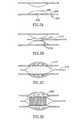
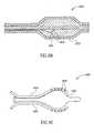
図2A〜2Eは、図1のフローチャートに従って血管または別の管状器官を治療する例示的プロセスを示す一連の図である。
図3は、本発明の例示的実施形態に従って治療した血管の体軸横断方向断面図である。
図4は、本発明の例示的実施形態に係る血管治療システムの略図である。
図5A〜5Dは、本発明の例示的実施形態に係る感圧穴を示す。
図6A〜6Hは、本発明の例示的実施形態に係る代替的カテーテルの設計を示し、そのうちの一部は前立腺治療に適する。
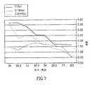
図7は、圧力および送達材料の量の関数としての浸透度を示す実験結果をまとめたグラフである。
図8は、本発明の例示的実施形態に係る送達システム内部で測定した圧力波形を示すグラフである。Exemplary non-limiting embodiments of the present invention are described with reference to the following description of embodiments in conjunction with the figures. The same structures, elements or parts appearing in more than one figure are generally labeled with the same or similar numbers in all the figures in which they appear.
FIG. 1 is a flowchart of a blood vessel treatment method according to an exemplary embodiment of the present invention.
2A-2E are a series of diagrams illustrating an exemplary process for treating a blood vessel or another tubular organ in accordance with the flowchart of FIG.
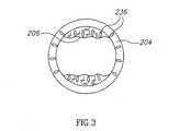
FIG. 3 is a transverse cross-sectional view of a blood vessel treated according to an exemplary embodiment of the present invention.
FIG. 4 is a schematic diagram of a vascular treatment system according to an exemplary embodiment of the present invention.
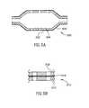
5A-5D illustrate a pressure sensitive hole according to an exemplary embodiment of the present invention.
6A-6H illustrate alternative catheter designs according to exemplary embodiments of the present invention, some of which are suitable for prostate treatment.
FIG. 7 is a graph summarizing experimental results showing penetration as a function of pressure and amount of delivery material.
FIG. 8 is a graph illustrating pressure waveforms measured inside a delivery system according to an exemplary embodiment of the present invention.
図1は、本発明の例示的実施形態に従って血管の壁に材料を塗布し、かつ/または材料を駆出する方法のフローチャートを示し、図2A〜2Eは該方法の行為を示す。図2A〜2Eについて、図1の説明と並行して論じる。装置および/または方法の変形について、以下で説明する。 FIG. 1 shows a flow chart of a method for applying and / or ejecting material to a vessel wall according to an exemplary embodiment of the present invention, and FIGS. 2A-2E will be discussed in parallel with the description of FIG. Variations on the apparatus and / or method are described below.
例示的方法
図1は、本発明の例示的実施形態に従って血管を治療する方法のフローチャート100である。Exemplary Method FIG. 1 is a
102で、血管200(図2A)の壁204における狭窄または他の問題が特定される。任意選択的に、狭窄はプラークの堆積206、例えば石灰化した埋積物202の堆積である。 At 102, a stenosis or other problem in the
104で、カテーテル治療システム210(図2B)が体内に挿入され、狭窄部に誘導される。任意選択的に、システム210は、例えば造影剤ポート(図示せず)または撮像装置(図示せず)を含み、問題を識別するためにも使用される。 At 104, a catheter treatment system 210 (FIG. 2B) is inserted into the body and guided to the stenosis. Optionally,
壁204に治療を施すために複数の開口(任意選択的に当初は密閉されている)214を含む、治療用バルーン212(図2B)が示されている。 A treatment balloon 212 (FIG. 2B) is shown that includes a plurality of openings (optionally initially sealed) 214 to provide treatment to the
106で、バルーン212は任意選択的に、堆積206に対しPTCAを実行するのに充分な圧力で膨張する(図2C)。堆積は、模式的に亀裂が入っているように示される。任意選択的に、開口214は、PTCAに使用される圧力(例えばバルーン内部で15〜20気圧)で少量だけ漏出するか、あるいは密閉状態に維持されるように構成される。 At 106, the
PTCAに代替または追加して、バルーン212は任意選択的に、ステント220を送達する(108)ために使用される(図2D)。 In lieu of or in addition to PTCA,
任意選択的に、ステント術および/またはPTCAは、バルーン212とは異なるバルーンを使用して実行され、かつ/または血管に材料を送達した後で実行される。任意選択的に、材料送達方法(例えば下述する高圧パルス)も、ステントを送達しかつ/またはそれを適位置に固定するために使用される。 Optionally, stenting and / or PTCA is performed using a different balloon than
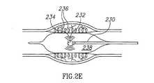
110で、1つ以上のプルーム236(図2E)がバルーンの穴から噴出され(下述する)、好ましくは壁204および/または壁上または壁内の堆積物206に浸透するように、高圧のパルスが提供される。任意選択的に、バルーンはこの注入前に、壁との接触および/または密閉圧力が確保されるように、膨張した状態を維持する。密閉および/または接触は任意選択的に、高圧で材料を壁に送達するのに役立ち、かつ/または壁内へのその浸透を補助する。 At 110, one or more plumes 236 (FIG. 2E) are ejected from the balloon holes (described below), preferably at high pressure so as to penetrate the
任意選択的に、例えば血管組織をステント術および/またはPTCAに適応させ、かつ/またはステント術および/またはPTCAが成功裏に完了することを確実にするために、送達はステント術および/またはPTCA後に遅延して行なわれる。例示的遅延は30〜90秒、例えば60秒である。 Optionally, delivery is performed with stenting and / or PTCA, for example to adapt vascular tissue to stenting and / or PTCA and / or to ensure that stenting and / or PTCA is successfully completed. Later, it will be delayed. An exemplary delay is 30-90 seconds, for example 60 seconds.
本発明の例示的実施形態では、光ファイバ230が光のパルスを送達し、それは充填材238(例えば生理食塩水)またはターゲット(図4の406)に吸収され、爆発232を引き起こす。爆発232からの衝撃および/または圧力波234はバルーン212の壁に伝わり、プルーム236の噴出を引き起こす。使用できる様々なメカニズムを下述する。本発明の例示的実施形態では、プルームは例えば薬剤または結合材と混合した生理食塩水とすることのできる充填材を含む。 In an exemplary embodiment of the invention,
本発明の例示的実施形態では、バルーンの総容積は爆発によって非常に大きくは増大せず、例えばバルーン直径は、せいぜい1%、5%、10%、またはより低め、中間的、もしくは、より高めの値、増大するだけである。任意選択的に、過剰拡張によって、例えば尿道のオーバーステント術および/または過剰拡張によって生じるかもしれない苦痛および/または破損を防止し、かつ/または減少するために、(例えば非コンプライアントバルーンを使用することによって)増大は回避される。 In exemplary embodiments of the invention, the total volume of the balloon does not increase significantly by explosion, for example, the balloon diameter is at most 1%, 5%, 10%, or lower, intermediate or higher. The value of only increases. Optionally (eg using non-compliant balloons) to prevent and / or reduce pain and / or breakage that may be caused by overdilatation, for example by urethral overstenting and / or overdilation Increase) is avoided.
代替的方法では、バルーン容積の著しい増大、例えば10%、20%、30%、またはより低め、中間的、もしくはより高めの値の増大が生じる。この増大は、プルーム236の流出後に、減少する場合もあればしない場合もある。本発明の例示的実施形態では、バルーン直径および/または圧力の変動または循環は、組織における材料の浸透および/または維持を補助するために使用される。本発明の例示的実施形態では、注入後または注入中の圧力の増大は、浸透点からの漏れを防止する。本発明の例示的実施形態では、注入前の圧力の低下は血管壁を弛緩させる。本発明の例示的実施形態では、浸透後の圧力(または波)の増加は、注入された材料の側方(例えば周方向)の分散を引き起こすために使用される。本発明の例示的実施形態では、注入中の圧力の程度が組織の厚さおよび従って有効浸透度を制御する。 Alternative methods result in significant increases in balloon volume, such as 10%, 20%, 30%, or lower, intermediate or higher values. This increase may or may not decrease after the
本発明の例示的実施形態では、バルーン212の膨張は、開口214の周囲のバルーン部分が血管の壁204と適正に接触し、おそらく漏れ防止および/またはより優れた浸透を確実にすることを保証する。任意選択的に、例えば0.5、1、3、または中間値もしくはそれ以上の気圧数の最小接触圧が達成される。 In an exemplary embodiment of the invention, inflation of the
ステント220が設けられる場合、開口214の幾つかはステントによって覆われるかもしれない。しかし、開口の大部分はそうならない。任意選択的に、開口はステントの支柱間に納まるように配置されるが、これは、例えば多数の開口が存在するため、一部の実施形態では必須ではない。 If a
材料の注入が完了しない場合、任意選択的に、接触圧を低減するために少し収縮し、次いで追加注入を実行することによって支援しながら、バルーン212を(例えば軸方向に、または回転によって)再配置することができる。異なる材料を注入させる場合、2回目の注入を使用することもできる。任意選択的に、両方の注入に同一のバルーンが使用される。代替的に、バルーンは交換することができる。任意選択的に、2つのバルーンが、例えば同一バルーンカテーテルおよび/または同一ガイドワイヤ上に1列に設けられる。 If material injection is not complete, optionally re-balloon 212 (eg, axially or by rotation) while assisting by performing a slight contraction to reduce contact pressure and then performing additional injections. Can be arranged. A second injection can also be used if different materials are injected. Optionally, the same balloon is used for both injections. Alternatively, the balloon can be exchanged. Optionally, two balloons are provided in a row, for example on the same balloon catheter and / or the same guidewire.
112で、バルーン212は取出しのために収縮される。任意選択的に、取出し中に開口から多少の漏出が発生する。任意選択的に、開口は、圧力が閾値未満になると再び密閉するように設計され、閾値はおそらく注入圧例えば10気圧より低い(例えば25%または50%低い)。任意選択的に、開口は、圧力が低下すると自己密閉するゴム状材料から形成される。圧力が増加すると、ゴム材の穿刺は拡大する。代替的に、または追加的に、開口に1つ以上のフラップが具備される。任意選択的に、フラップは一方向弁として働き、フラップは外側に開くことができるが、内側には開かない。 At 112, the
図3は、壁204および堆積物206のプルーム236を示す、血管200の体軸横断方向断面図である。例えば接着剤のような構造材が注入される場合、プルームは血管を開いた状態に保持するように働くことができることが分かる。本発明の幾つかの実施形態では、材料の少なくとも一部は壁の外側に提供される。1例としては、バルーンは例えば軸方向パターンまたは螺旋状パターンの隆線を有し、穴は材料注入のために隆線の基部に設けられる。この注入材料の一部または全部を、バルーンと血管壁との間に閉じ込められた状態に維持することができる。 FIG. 3 is a cross-sectional cross-sectional view of
例示的システム
図4は、図1〜3の助けを借りて示した方法を実行するために使用することのできるような、本発明の例示的実施形態に係る例示的システム400を示す。Exemplary System FIG. 4 illustrates an
最初に、システム400の一般的に体外の部分を参照すると、レーザー源410は、爆発232用の光のパルスを提供するために使用される。任意選択的に、制御装置427は、例えばプルーム236の浸透度および/またはその材料の量を制御するのに役立つ全出力、最大出力、パルス幅、および/または繰返し数のような、パルスの1つ以上のパラメータを制御するために使用される。 Initially, referring to the generally extracorporeal portion of
本発明の例示的実施形態では、バルーンの温度制御が行なわれる。任意選択的に、例えばバルーン内の流体循環と結合されたバルーン内の温度センサを使用して、閉ループ制御が使用される。任意選択的に、バルーンの実際の内容物を交換する必要が無いように、任意選択的にバルーン内に熱交換器が設けられる。任意選択的に、熱交換器は管腔内の1つ以上のコイルまたは金のような熱伝導性ウェブの形を取る。代替的に、開ループ冷却、例えば流体および/またはバルーンの事前冷却が使用される。任意選択的に、バルーンの温度が所望の値より高くなると、ユーザに警告し、かつ/または追加のエネルギー供給を防止するように安全装置が使用される。任意選択的に、冷却流体を提供するために使用される管腔は、エネルギー供給導管(例えばファイバ、ワイヤ)を冷却するために使用される。 In an exemplary embodiment of the invention, balloon temperature control is provided. Optionally, closed loop control is used, for example using a temperature sensor in the balloon coupled with fluid circulation in the balloon. Optionally, a heat exchanger is optionally provided in the balloon so that the actual contents of the balloon need not be exchanged. Optionally, the heat exchanger takes the form of one or more coils in the lumen or a thermally conductive web such as gold. Alternatively, open loop cooling, eg fluid and / or balloon pre-cooling is used. Optionally, a safety device is used to alert the user and / or prevent additional energy supply when the balloon temperature rises above a desired value. Optionally, the lumen used to provide the cooling fluid is used to cool the energy supply conduit (eg, fiber, wire).
生理食塩水源412は任意選択的に、バルーン212を膨張させるために使用される。任意選択的に、インパルス源418は、レーザー源410の代わりに、またはそれに加えて、バルーン212内で圧力波を発生させるために使用される。
本発明の例示的実施形態では、源418は、例えばマッサージ効果をもたらすように、バルーン内で圧力波を発生させるために使用される。代替的に、または追加的に、例えば注入材料が開口に接着するのを防止するために、バルーンに振動がもたらされる。 In an exemplary embodiment of the invention, the
外部圧力インパルス源およびレーザーインパルス源が異なる型の効果をもたらすことができることに留意されたい。レーザー源は、おそらく低い圧出量および/または低い出力でも、非常に鋭いインパルスを提供することができる。圧力源、例えば体外の源は一般的に、それほど鋭くないインパルスのみを提供することができるが、そのようなインパルスはかなりの出力および/または量を含むことができる。 Note that external pressure impulse sources and laser impulse sources can provide different types of effects. The laser source can provide a very sharp impulse, perhaps even with low pumping volume and / or low power. Although a pressure source, eg, an extracorporeal source, can generally provide only less severe impulses, such impulses can include significant power and / or volume.
任意選択的に、両方の型の源は、任意選択的に同期して、同時に使用される。代替的に、または追加的に、それらの間で遅延して使用される。各源は、1つ以上のパルスを提供し、それらの一部だけが同期するように使用することができる。 Optionally, both types of sources are used simultaneously, optionally synchronously. Alternatively or additionally, it is used with a delay between them. Each source can provide one or more pulses and only some of them can be used to synchronize.
本発明の例示的実施形態では、使用する源の型は、カテーテルの長さに依存する。例えば、カテーテルが短い(かつ容積要件が大きい)前立腺の場合、シリンジ、ポンプ、またはガス付勢システムのような圧力源を使用することができる。圧力を送達する管腔が長くかつ細い冠状血管で、(かつ容積要件が低い)、レーザーに基づく解決策が最も適しているかもしれない。 In an exemplary embodiment of the invention, the type of source used depends on the length of the catheter. For example, if the catheter is a short (and large volume requirement) prostate, a pressure source such as a syringe, pump, or gas energized system can be used. Lasers based solutions may be most suitable with long and thin coronary vessels delivering pressure (and low volume requirements).
以下で他のインパルス源について述べる。 Other impulse sources are described below.
造影剤416の源は、生理食塩水412に造影剤を提供するために使用することができ、かつ/または血管200の撮像を支援するために使用することができる。任意選択的に、当業界で公知の他のツール、例えば塞栓フィルタが使用される。 The source of
プルーム236として提供される薬剤または他の材料420の源も任意選択的に使用され、例えば生理食塩水源412に、またはそこから下流に供給することができる。代替的に、または追加的に、材料420は生理食塩水の代わりにバルーンを膨張させるために使用される。 A source of medication or
一部の実施形態では、送達される材料および/または造影剤は、生理食塩水(または他の流体)を使用して提供する代わりに、またはそれに加えて、バルーンが体外にある間に、例えば針注入によってバルーン212に直接提供される。 In some embodiments, the delivered material and / or contrast agent is provided instead of, or in addition to, using saline (or other fluid) while the balloon is outside the body, for example Provided directly to the
本発明の例示的実施形態では、バルーン212は、1つ以上の盲開口414を備えた2つ以上の層から形成される。任意選択的に、開口は内層のみ、および/または外層のみに形成される。さらなる詳細は以下に提供する。任意選択的に、補強要素404、例えばファイバまたはコードが設けられる。任意選択的に、要素404は非弾性であり、PTCAに必要である以上のバルーン212の過剰拡張を防止する。代替的に、または追加的に、要素404は、引裂きが開口から伝搬してバルーン212を破断するのを防止するために、開口404付近に配置される。 In the exemplary embodiment of the invention, the
本発明の例示的実施形態では、要素404はグリッドを含み、開口はグリッドのセル内に形成される。任意選択的に、グリッドは不均一である。任意選択的に、非グリッド配置、例えばランダムフェルト状配置または螺旋状配置が使用される。 In an exemplary embodiment of the invention,
本発明の例示的実施形態では、バルーンの過剰膨張を防止するために金属ステント状フレームが使用される。1例としては、ステント状ケージは、ひとたび特定の半径に達すると拡張を停止するように設計される。バルーンは膨張し、ケージはその点を越えるバルーンの膨張を防止するが、依然としてそこからの流体の噴出は可能である。任意選択的に、ケージは維持され、ステントとして働く。任意選択的に、ケージは例えばニチノールから形成されたスプリングバック型である。 In an exemplary embodiment of the invention, a metal stent-like frame is used to prevent balloon over-inflation. As an example, a stent-like cage is designed to stop expanding once it reaches a certain radius. The balloon inflates and the cage prevents inflation of the balloon beyond that point, but fluid can still be ejected therefrom. Optionally, the cage is maintained and acts as a stent. Optionally, the cage is a springback type formed, for example, from nitinol.
本発明の例示的実施形態では、2つの管がバルーン212、膨張管腔402、および光ファイバ230に通じる。任意選択的に、流体除去管腔も提供され(図示せず)、任意選択的に、バルーン212を収縮することなく、バルーン212の内容物を(例えば生理食塩水を接着剤と)交換するために使用される。 In the exemplary embodiment of the invention, two tubes lead to
任意選択的に、複数のファイバ230がバルーンに設けられ、あるいは例えばレーザーエネルギーをバルーン212内でより適正に分散させるように、複数のレーザー出射点、例えば2個、3個、4個、もしくは5個またはそれ以上の出射点がファイバ230に設けられる。図6Aは、ファイバ602が複数の分枝604に分岐し、その各々が局所的エネルギー源として働くことのできるシステム600を示す。この配置は、バルーンにおける衝撃/圧力波の分散を制御するために使用することができる。本発明の例示的実施形態では、ファイバ602は220ミクロンの直径を有し、ファイバ604は各々100〜120ミクロンの直径を有する。任意選択的に、ファイバ602の直径は充分な量のパワーを伝達する必要性によって設定される。代替的に、または追加的に、直径は、治療領域に通じる血管内でファイバを撓曲させる必要性によって決定される。また、図6Aには、治療システムに設けることのできる他の部品、すなわち、任意選択的にそれ自体のチャネル610内を進むガイドワイヤ608、任意選択的に圧力応動開口612を含むバルーン606、およびガイドシース614も示されている。 Optionally, a plurality of
本発明の例示的実施形態では、ファイバがランダムな方向を向くのを防止するために、ファイバの例えば内部枠組またはバルーンの基部への堅固な取付けが設けられる。任意選択的に、ファイバはそれが軸方向にとどまるように剛性に作られる。代替的に、または追加的に、ファイバは、ガイドワイヤ用に使用され略軸方向を維持する内部管腔に取り付けられる。任意選択的に、ファイバは、偶発的な貫通を防止するために、バルーンの表面から離れる方向に向けられる。任意選択的に、近傍領域は反射性コーティングで被覆される。 In an exemplary embodiment of the invention, a rigid attachment of the fiber to the base of the inner frame or balloon, for example, is provided to prevent the fiber from pointing in a random direction. Optionally, the fiber is made rigid so that it remains axial. Alternatively or additionally, the fiber is attached to an internal lumen that is used for the guidewire and maintains a generally axial orientation. Optionally, the fiber is directed away from the surface of the balloon to prevent accidental penetration. Optionally, the neighboring area is coated with a reflective coating.
図4に戻って説明すると、任意選択的に、爆発232の位置および/または空間的範囲を分散させかつ/またはそれ以外で制御するために、ファイバ230用のターゲットまたはミラー406が設けられる。ターゲットは任意選択的にターゲット位置でエネルギーを吸収するために使用され、ミラーは任意選択的に、バルーンに充填する流体内にエネルギーを再分散させるのを助けるために使用される。本発明の例示的実施形態では、ターゲットは炭素または酸化アルミニウムから形成される。任意選択的に、ターゲットはその付近で流体を加熱および沸騰させる。代替的に、または追加的に、ターゲット自体が少なくとも部分的に爆発または蒸発する。任意選択的に、レーザー410によって使用される波長は、使用される流体および/またはそれに混合された1つ以上の不純物(例えば染料または懸濁粒子)によって吸収される。任意選択的に、不純物はレーザーエネルギーを選択的に吸収するように選択される。任意選択的に、濃度は、レーザーエネルギーの浸透度が既知の量であり、かつ既知の効果(例えばインパルスの先鋭度および焦点の空間分布)を有するように選択される。任意選択的に、使用される不純物は、アイフォト処理に使用されるもの、例えばインドシアニングリーンである。 Returning to FIG. 4, optionally, a target or
ターゲット406は任意選択的に金属要素である。代替的に、または追加的に、ターゲット406はアジ化銀のような分解要素である。
本発明の例示的実施形態では、ターゲットは、レーザー光を投射されたときにレーザーエネルギーを吸収しかつ既知の量のガスを形成する材料から作られる。任意選択的に、ターゲット自体が爆発する。任意選択的に、追加レーザーパルスでもターゲットの一部の蒸発が生じるように、ターゲットは複数のターゲット層および/またはかなりの厚さを含む。 In an exemplary embodiment of the invention, the target is made of a material that absorbs laser energy and forms a known amount of gas when projected with laser light. Optionally, the target itself explodes. Optionally, the target includes a plurality of target layers and / or significant thicknesses so that additional laser pulses cause evaporation of a portion of the target.
任意選択的に、ターゲットは、外殻が使用される波長を透過しかつその内容物が透過しないカプセルを含む。 Optionally, the target comprises a capsule that is transparent to the wavelength at which the outer shell is used and not its contents.
任意選択的に、ターゲットは、レーザーエネルギーを送達するファイバ先端に、例えば1層の染料または金属コーティングとして形成される。 Optionally, the target is formed on the fiber tip delivering laser energy, for example as a layer of dye or metal coating.
本発明の例示的実施形態では、レーザー源はNd:YAGレーザーであり、1.064ミクロンの波長を吸収することのできるドーパントを使用する。ドーパント例として炭素および金属粒子がある。様々なレーザー波長、例えばダイオードレーザーに0.800から1.100ミクロンの間で吸収する他の材料を使用することができる。 In an exemplary embodiment of the invention, the laser source is a Nd: YAG laser and uses a dopant capable of absorbing a wavelength of 1.064 microns. Examples of dopants include carbon and metal particles. Other materials that absorb between 0.800 and 1.100 microns can be used for various laser wavelengths, such as diode lasers.
本発明の例示的実施形態では、レーザー源は、2.9ミクロンでエルビウムパルスレーザーから水に吸収される波長、例えば2.1ミクロンのホルミウムパルスレーザーを、または他の1.9ミクロンより高い波長(例えば1940nm)を提供する。水の吸収スペクトルは周知であり、吸収係数の高い(かつ伝達手段が利用可能である)波長を使用することができる。任意選択的に、衝撃/圧力波は、ビームに対しより低いか高い吸収係数および/または異なる形状を選択することによって形成することができる。任意選択的に、レーザーに影響された材料がバルーンの外部に注入されるのを防止するために、保護障壁が設けられる。本発明の例示的実施形態では、バルーンまたは膜がファイバ先端の周囲に設けられる。任意選択的に、膜はバルーン内部に設けられる。任意選択的に、ファイバ先端と開口との間に流体経路が存在するが、この経路は間接的であり、熱の影響を受けた材料の噴出を著しく低減する。バルーンの充填は必ずしも妨害されない。任意選択的に、ファイバ先端は開口から離隔され、例えばバルーンの外側に位置する。任意選択的に、密閉状態を維持しエネルギーを吸収するための予め定められたカプセルが設けられる。 In an exemplary embodiment of the invention, the laser source is a wavelength that is absorbed into water from an erbium pulsed laser at 2.9 microns, such as a 2.1 micron holmium pulsed laser, or other wavelengths higher than 1.9 microns. (Eg 1940 nm). The absorption spectrum of water is well known and wavelengths with a high absorption coefficient (and for which transmission means are available) can be used. Optionally, the shock / pressure wave can be formed by selecting a lower or higher absorption coefficient and / or a different shape for the beam. Optionally, a protective barrier is provided to prevent laser affected material from being injected outside the balloon. In an exemplary embodiment of the invention, a balloon or membrane is provided around the fiber tip. Optionally, a membrane is provided inside the balloon. Optionally, there is a fluid path between the fiber tip and the opening, but this path is indirect and significantly reduces the ejection of thermally affected material. Balloon filling is not necessarily disturbed. Optionally, the fiber tip is spaced from the opening, eg, located outside the balloon. Optionally, a predetermined capsule is provided for maintaining a sealed state and absorbing energy.
任意選択的に、例えば衝撃/圧力波のための経路長を設定し、衝撃/圧力波を所望の角度でバルーン壁に衝突させるように方向付け、かつ/またはエネルギーを吸収し、かつ/または一部の方向のインパルス発生率低下させるために、爆発232の効果を誘導するように1つ以上の内部バフル408が使用される。任意選択的に、誘導は波を空間的かつ/または時間的により均等に分布させることを含む。 Optionally, for example, set a path length for the shock / pressure wave, direct the shock / pressure wave to strike the balloon wall at a desired angle, and / or absorb energy and / or one One or more
爆発232はバルーン212内部に図示されているが、それはバルーンの外側で、例えばバルーン212の膨張可能部から例えば遠位方向または近位方向に30mm、20mm、15mm、10mm、5mm、またはそれ以下の距離内で達成することができる。任意選択的に、爆発の領域は強化層、例えば1層の任意選択的に硬質のプラスチックまたは金属で包囲され、それはカテーテル210の破断を防止し、かつ/または爆発波234をバルーンに向けて誘導するのを助けるように働く。
本発明の例示的実施形態では、バルーンはナイロン12またはPETのような標準材料から形成される。本発明の例示的実施形態では、バルーンはその用途に応じたサイズに、例えば冠状血管または脳血管のような比較的小さい血管の場合1mm、2mm、2.5mm、3mm、または4mmに形成される。例えば静脈および前立腺ではより大きい直径(例えば7〜10mm)を使用することができる。バルーンはまた、例えば石灰化または大動脈弁狭窄を治療するために、大動脈または腹部大動脈の治療用のサイズとすることもできる。 In an exemplary embodiment of the invention, the balloon is formed from a standard material such as nylon 12 or PET. In an exemplary embodiment of the invention, the balloon is sized according to its application, eg, 1 mm, 2 mm, 2.5 mm, 3 mm, or 4 mm for relatively small blood vessels such as coronary or cerebral blood vessels. . For example, larger diameters (eg, 7-10 mm) can be used for veins and prostate. The balloon can also be sized for the treatment of the aorta or abdominal aorta, for example to treat calcification or aortic stenosis.
例示的に提供される材料
構造材
本発明の例示的実施形態では、注入される材料は、それが注入される組織の構造的(例えば機械的)性質を変化させる構造材である。構造材の1例として、硬化する接着剤または結合剤、例えばBioglue Surgical Adhesive、Dermabondシアノアクリレートまたはコラーゲン(特定の形態)がある。任意選択的に、非硬化材、例えばシリコンゲル、カーボンナノチューブ、コラーゲン(特定の形態)、炭素繊維、プラスチック繊維、および/またはガラス繊維が使用される。血管の圧潰および/または解離を防止するように血管を硬化および/または強化する目的は、たとえ壁204全体を硬質にしなくても達成されることが注目される。使用される材料および/または所望の効果に基づいて、様々な量の材料を注入することができる。例えば組織の体積の5%、10%、20%、30%、50%、またはより低め、中間的、またはより高めの割合が、注入材料の量として使用される。任意選択的に、注入は空間的に稠密ではなく、最小限または最大限例えば0.3mm、0.5mm、1mm、2mmの寸法の例えば非注入領域がある。任意選択的に、注入は組織の厚さのごく一部分だけを満たし、例えば組織の縁の10%以内には実質的に到達しない。任意選択的に、注入材料は、長さ(半径方向)対幅の比が1:1または1:2未満の特定の空間形態に、例えば長寸の針に集まる。別の例示的構成は平坦な構成であり、プルームは2:1、3:1、またはそれ以上の高さ対幅の比を有する。所望の機械的および/または生物学的変化が達成されることを前提として、一般的に、より少量の注入材料が望ましい。Exemplary Material Materials Provided In an exemplary embodiment of the invention, the injected material is a structural material that alters the structural (eg, mechanical) properties of the tissue into which it is injected. One example of a structural material is an adhesive or binder that hardens, such as Bioglue Surgical Adhesive, Dermabond cyanoacrylate or collagen (specific forms). Optionally, non-hardening materials such as silicon gel, carbon nanotubes, collagen (specific forms), carbon fibers, plastic fibers, and / or glass fibers are used. It is noted that the purpose of hardening and / or strengthening the blood vessel to prevent crushing and / or dissociation of the blood vessel is achieved even without making the
本発明の例示的実施形態では、注入後、壁204は弾性的に変化し、例えば弾性材料が注入された場合には弾性が高くなり、可鍛材料が注入された場合には弾性が低下する。 In an exemplary embodiment of the invention, the
任意選択的に、構造材は、生物活性材または他の材料、例えば下述する種類の材料と混合される。 Optionally, the structural material is mixed with a bioactive material or other material, such as the types of materials described below.
本発明の例示的実施形態では、構造材は、それが注入される組織に、少なくともかなりの量は通常存在しない種類のものである。 In an exemplary embodiment of the invention, the structural material is of a type that usually does not exist at least in significant amounts in the tissue into which it is injected.
任意選択的に、構造材はステントの代わりに、またはそれに加えて提供される。任意選択的に、構造材を提供するため、あまり硬質でないステントを使用する。任意選択的に、接着剤の注入を随伴するステントは可撓性が、適切な標準ステントより少なくとも50%、70%、80%、またはそれ以上高く、かつ/または金属含有量が50%、70%、80%、またはそれ以上減少する。本発明の例示的実施形態では、金属の厚さの低減は、より小さい管内、例えば2mm、1mm、0.7mm、0.5mm、またはそれ以下の体内管内のステント留置を可能にする。任意選択的に、ステントの材料の量は、医師によって正しいと想定される目安に比べて低減される。任意選択的に、より軟質の材料、例えば薄い(厚いの反対語)プラスチックがステントに使用される。任意選択的に、ステントは生物分解性/吸収性、例えば生物分解性プラスチックまたは糖から作られる。任意選択的に、生物分解性ステントは、ステントの大きい断片が血流内に流入するのを血管壁が防止するように、バルーンによって血管壁内またはその付近に注入される構造材(例えば接着剤)にステントを接着させることによって、より安全になる。 Optionally, the structural material is provided in place of or in addition to the stent. Optionally, a less rigid stent is used to provide the structural material. Optionally, a stent with adhesive injection is at least 50%, 70%, 80%, or more flexible than a suitable standard stent and / or has a metal content of 50%, 70 %, 80%, or more. In an exemplary embodiment of the invention, the reduction in metal thickness allows for stent placement in smaller vessels, such as 2 mm, 1 mm, 0.7 mm, 0.5 mm, or less body vessels. Optionally, the amount of stent material is reduced compared to a guideline that is assumed correct by the physician. Optionally, softer materials, such as thin (opposite for thick) plastic, are used for the stent. Optionally, the stent is made of biodegradable / absorbable, eg biodegradable plastic or sugar. Optionally, a biodegradable stent is a structural material (eg, an adhesive) that is injected into or near the vessel wall by a balloon so that the vessel wall prevents large fragments of the stent from entering the bloodstream. ) To make the stent more secure.
任意選択的に、ステント材料の低減により複雑さを低減することができる。 Optionally, complexity can be reduced by reducing stent material.
任意選択的に、構造材はファイバを含み、任意選択的に、渦状に閉じ、時間が経つとファイバを分解して解放する糖または特定のプラスチックのような材料で被覆されたファイバを含む。 Optionally, the structural material comprises a fiber, optionally a fiber that is closed in a vortex and coated with a material such as sugar or certain plastics that breaks down and releases the fiber over time.
任意選択的に、材料は、中実組織内に無いとき(例えば血流中にあるとき)消散されかつ/または分解される。任意選択的に、材料は生物分解性である。任意選択的に、これらの性質を使用して、接着剤が血管壁を通過して組織に浸透する場合に、危険性を低減する。 Optionally, the material is dissipated and / or decomposed when not in solid tissue (eg, in the bloodstream). Optionally, the material is biodegradable. Optionally, these properties are used to reduce the risk if the adhesive penetrates the tissue through the vessel wall.
任意選択的に、材料は組織および/または血液と接触して硬化する。 Optionally, the material hardens in contact with tissue and / or blood.
任意選択的に、注入材料は粒子の懸濁液を含む。任意選択的に、流体が圧搾されかつ/または狭い流路内で移動が行なわれる組織内にあるときに、懸濁粒子は集塊状になり、構造効果を有する。血液中で、そのような粒子は分散する。任意選択的に、粒子は時間が経つと集合して硬化する。任意選択的に、粒子は、内皮細開口に匹敵するサイズ(またはそれ以上)および/または細胞間空間に匹敵するサイズになるように選択される。 Optionally, the infusion material comprises a suspension of particles. Optionally, the suspended particles become agglomerated and have a structural effect when the fluid is squeezed and / or in tissue where movement takes place in a narrow channel. Such particles are dispersed in the blood. Optionally, the particles aggregate and cure over time. Optionally, the particles are selected to be sized (or larger) comparable to the endothelial microaperture and / or sized comparable to the intercellular space.
任意選択的に、第1成分材料が壁に注入され、次いで第2成分材料(例えば触媒または硬化剤)が注入される2成分材料(例えばPMMA)が使用される。そのような材料は血液中に消散し、材料の充分な濃度が集合しかつ/または相互作用することは防止されると予想される。任意選択的に、そのような反応中にもたらされる熱を使用して、再狭窄をさらに防止する。 Optionally, a two component material (eg PMMA) is used in which a first component material is injected into the wall and then a second component material (eg catalyst or curing agent) is injected. Such materials are expected to dissipate into the blood and prevent a sufficient concentration of the material from collecting and / or interacting. Optionally, heat provided during such a reaction is used to further prevent restenosis.
本発明の例示的実施形態では、材料の注入後、材料がそれに膠着するのを防止するために、バルーン212は動かされる。任意選択的に、バルーンは材料の硬化時間中に回転される。代替的に、または追加的に、清浄な生理食塩水(または他の生理学的に受け入れ可能な)溶液が低圧でバルーン212から「滲出」し、該滲出が開口414を清浄化し、かつ/または注入材料の表面残渣を除去する。任意選択的に、滲出材料は注入材料の硬化を防止する触媒または溶媒を含む。任意選択的に、バルーンは、構造材が接着されない材料、例えばテフロンまたはシリコン油コーティングを被覆される。任意選択的に、材料が硬化プロセスを完了する前に、バルーンは取り出される。例えば30分の硬化プロセスを持つ材料を使用し、5分後にバルーンを取り除く。任意選択的に、システムを使用するためのキットにタイマが設けられ、該タイマは、バルーンを取り除き、硬化を防止する時間を指示する。 In an exemplary embodiment of the invention, after injection of the material, the
任意選択的に、接着剤が硬化または半硬化する間、バルーンは膨張した状態に維持される。任意選択的に、当業界で公知の通り、血流バイパス経路、例えば導管がバルーンに設けられる。 Optionally, the balloon is maintained in an inflated state while the adhesive is cured or semi-cured. Optionally, a blood flow bypass path, such as a conduit, is provided in the balloon, as is known in the art.
本発明の例示的実施形態では、バルーンは、印加圧力に対する血管の壁の応答を測定し、かくして治療の効果を評価するために使用される圧力センサを含む。 In an exemplary embodiment of the invention, the balloon includes a pressure sensor that is used to measure the response of the vessel wall to the applied pressure and thus evaluate the effectiveness of the treatment.
染料および/または放射線不透過材
構造材に代替または追加して、染料/マーカが注入される。任意選択的に、染料は、後で治療する領域(例えば外科手術のための癌の範囲)を識別するために使用される。代替的に、または追加的に、染料/マーカは放射線不透過材であり、それはステント位置または治療位置の標識として役立つ。任意選択的に、例えば、特定の治療および/またはそのパラメータを治療血管の画像から読み取ることができるように、注入はパターン化される。Dye and / or radiopaque material Dye / marker is injected in place of or in addition to structural material. Optionally, the dye is used to identify areas to be treated later (eg, a range of cancer for surgery). Alternatively or additionally, the dye / marker is a radiopaque material, which serves as a stent or treatment location indicator. Optionally, the injection is patterned so that, for example, a particular treatment and / or its parameters can be read from the image of the treatment vessel.
任意選択的に、染料成分は、血管壁および/または管腔内に注入される材料の量を推定するために使用される。 Optionally, the dye component is used to estimate the amount of material injected into the vessel wall and / or lumen.
軟化材
本発明の例示的実施形態では、プラークおよび/または他の組織を軟化させる材料が注入される。任意選択的に、PTCA処置でプラークを平坦化するだけでなく、そこからの排液も行なわれるように、この注入はPTCA処置の前に行なわれる。任意選択的に、構造材はPTCAおよび/または軟化の後に注入される。任意選択的に、軟化したプラークから排液するために、例えばガイドワイヤに沿って設けられまたはバルーンから延出する、例えば前進可能な尖端をカテーテルに使用して、プラークに排液穴が形成される。Softener In an exemplary embodiment of the invention, a material that softens plaque and / or other tissue is injected. Optionally, this infusion is performed prior to the PTCA treatment so that not only will the PTCA treatment flatten the plaque but also drain it therefrom. Optionally, the structural material is injected after PTCA and / or softening. Optionally, a drain hole is formed in the plaque, for example using an advanceable tip on the catheter, e.g. provided along the guide wire or extending from the balloon, to drain from the softened plaque. The
任意選択的に、プラークを吸い出すために吸引管腔が設けられる。任意選択的に、吸引管腔に沿って尖端が設けられる。 Optionally, a suction lumen is provided to suck out plaque. Optionally, a tip is provided along the suction lumen.
生物活性材
本発明の例示的実施形態では、注入材料は生物活性材、例えばRapamycinタキソールのような炎症および/または組織増殖を防止する材料、免疫感作または脱感作剤、および/または遺伝子治療材料である。任意選択的に、材料は、1〜3ヶ月のような期間にわたって徐放されるように、例えばナノ粒子に被包される。他の例示的期間は1週間未満、1週間から1ヶ月の間、および3ヶ月から6ヶ月の間またはそれ以上である。In an exemplary embodiment of the invention, the infusion material is a bioactive material, such as a material that prevents inflammation and / or tissue growth, such as Rapamycin taxol, an immunization or desensitization agent, and / or gene therapy. Material. Optionally, the material is encapsulated, for example in nanoparticles, so as to be released over a period such as 1-3 months. Other exemplary periods are less than one week, between one week and one month, and between three months and six months or more.
任意選択的に、生物活性材は構造材を補完する。例えば、生物活性材が線維化を引き起こすなど長期効果を有する一方、構造材は消散するまで短期効果を有する。そのような対の1例としてPLAおよびラパマイシンがある。任意選択的に、短期効果は即座であり、つまり数分または数時間以内に始まり、例えば1日か2日まで続く。長期効果は例えば数ヶ月または数年間持続し、例えば1日または1週間後から開始する。 Optionally, the bioactive material complements the structural material. For example, bioactive materials have long-term effects such as causing fibrosis, while structural materials have short-term effects until they dissipate. One example of such a pair is PLA and rapamycin. Optionally, the short-term effect is immediate, i.e. starts within minutes or hours and lasts for example up to 1 or 2 days. Long-term effects last for example months or years, starting for example after a day or a week.
本発明の例示的実施形態では、本発明の一部の実施形態に係る方法および/または装置は、使用する薬剤および/または他の材料の量の低減を可能にする。本発明の例示的実施形態では、組織内への直接挿入、および任意選択的に自己密閉する小さい貫通穴は、血液内への漏出、および考えられるその副作用を軽減する。任意選択的に、材料の噴出後、さらなる漏出を防止するために、バルーンは膨張状態を維持する。本発明の例示的実施形態では、材料の表面対容量比は、例えば血管内への材料の複数の細く深い挿入を確実にするっことのできる高圧のため、表面塗布の場合より優れている。本発明の例示的実施形態では、短いパルスを使用する無針注入の使用は、患者に与える苦痛を軽減し、かつ/または治療時間を短縮させることができる。 In exemplary embodiments of the present invention, methods and / or devices according to some embodiments of the present invention allow for a reduction in the amount of drugs and / or other materials used. In an exemplary embodiment of the invention, the direct insertion into the tissue, and optionally a small through hole that self-seals, reduces leakage into the blood and its possible side effects. Optionally, after ejection of the material, the balloon remains inflated to prevent further leakage. In an exemplary embodiment of the invention, the surface to volume ratio of the material is superior to that of surface application, for example due to the high pressure that can ensure multiple thin and deep insertions of the material into the blood vessel. In an exemplary embodiment of the invention, the use of needleless injection using short pulses can reduce pain and / or reduce treatment time for the patient.
本発明の例示的実施形態では、生物活性材はDNAまたは他のゲノム材料、例えば(様々な種類の)RNA、ウィルス、およびプラスミドである。In an exemplary embodiment of the invention, the bioactive material is DNA or other genomic material, such as (various types of) RNA, viruses, and plasmids.
本発明の例示的実施形態では、注入材料の量は10cc未満、例えば1cc未満であり、例えば冠状血管の場合、0.01〜0.03ccである。 In an exemplary embodiment of the invention, the amount of infusion material is less than 10 cc, for example less than 1 cc, for example 0.01-0.03 cc for coronary vessels.
本発明の例示的実施形態では、注入材料は、例えば有効期間の短い調合薬の場合、治療時またはその近くに調製され、かつ/または提供される。 In an exemplary embodiment of the invention, the infusion material is prepared and / or provided at or near treatment, for example in the case of a short-lived formulation.
開口製造方法
開口(214、414)を製造するために様々な方法を使用することができる。図5A〜5Dは、PTCA処置時に開口が閉じたまま維持され、材料注入が行なわれるときに開口する、様々な開口の設計を示す。任意選択的に、開口のサイズは20ミクロン、30ミクロン、50ミクロン、100ミクロン、またはその他のより小さめ、中間的、もしくはより大きめの寸法である。任意選択的に、中心間距離は0.3mm、0.5mm、0.7mm、またはより小さめ、中間的、もしくはより大きめの距離である。Opening Manufacturing Methods Various methods can be used to manufacture the openings (214, 414). 5A-5D show various aperture designs that remain open during PTCA procedures and open when material injection is performed. Optionally, the size of the opening is 20 microns, 30 microns, 50 microns, 100 microns, or other smaller, intermediate or larger dimensions. Optionally, the center-to-center distance is 0.3 mm, 0.5 mm, 0.7 mm, or a smaller, intermediate or larger distance.
本発明の一部の実施形態では、バルーンが最初に形成され、次いで開口が形成される。他の実施形態では、開口を持つ第1層が形成され、次いで開口の無い第2層がその上に設けられる。図5Aは、これらの後者の組の性質を持つバルーン設計500を示し、内層502はそこに形成された多数の開口504を有し、外層506は連続している。任意選択的に、この設計は、開口502と周囲の血液との間の(クロット形成のような)負の相互作用を防止する。 In some embodiments of the invention, the balloon is first formed and then the opening is formed. In other embodiments, a first layer with an opening is formed, and then a second layer without an opening is provided thereon. FIG. 5A shows a
図5Bは、開口層512および518間に中実層516が設けられた、代替的設計510を示す。任意選択的に、外開口にはクロット形成を防止する材料が設けられる。 FIG. 5B shows an
中実層の強度および/または開口の度は、特定の閾圧力より高いときだけ所望の引裂き特性を持つように構成される。 The strength of the solid layer and / or the degree of opening is configured to have the desired tear properties only when it is above a certain threshold pressure.
図5Cは、バルーンの単一層522に複数の開口524が形成された設計520を示す。任意選択的に、穴位置の層の厚さは、バルーンの壁厚の20〜70%である。任意選択的に、穴位置の層は事前に脆弱化され、例えば穿刺される。 FIG. 5C shows a
本発明の例示的実施形態では、エキシマまたは他の型のレーザーを使用して、バルーンから材料をアブレートし、それにより開口を形成する。任意選択的に、レーザー浸透を制御するために、2つのバルーン層の間に光反射層が設けられる。代替的に、または追加的に、2つの層の吸収特性は異なってもよい。任意選択的に、異なる層は異なる材料から形成される。 In an exemplary embodiment of the invention, an excimer or other type of laser is used to ablate material from the balloon, thereby forming an opening. Optionally, a light reflecting layer is provided between the two balloon layers to control laser penetration. Alternatively or additionally, the absorption characteristics of the two layers may be different. Optionally, the different layers are formed from different materials.
本発明の例示的実施形態では、バルーン212に貫通開口または盲開口を形成するために、熱針を使用する。 In an exemplary embodiment of the invention, a hot needle is used to form a through-opening or blind opening in the
本発明の例示的実施形態では、ウォータジェットを使用して、孔を開ける。 In an exemplary embodiment of the invention, a water jet is used to drill holes.
任意選択的に、開口の形成中に、開口を所望する領域以外でのバルーンの損傷を防止するために、マスクを使用する。 Optionally, during the formation of the opening, a mask is used to prevent balloon damage outside the area where the opening is desired.
本発明の例示的実施形態では、バルーンを製造するために使用される型は、例えば型内でプラスチックチューブをブロー成形することによってバルーンを形成するときに、貫通穴または盲穴を作る微小突起を含む。代替的に、または追加的に、型および/またはブローチューブは、塩または別の水溶性および/または生物分解性材料の粒子で被覆され、それは後で洗い流されて、微細な開口が残る。 In an exemplary embodiment of the invention, the mold used to manufacture the balloon has microprojections that create through holes or blind holes when forming the balloon, for example, by blow molding a plastic tube within the mold. Including. Alternatively or additionally, the mold and / or blow tube are coated with particles of salt or another water-soluble and / or biodegradable material that is subsequently washed away leaving a fine opening.
図5Dは、複数の開口534に少なくとも一時的充填材536が含まれるバルーン設計530を示す。充填材536が無くなる(自然に、または取り除かれる)と、開口は実現の仕方によって部分孔または貫通孔となる。本発明の例示的実施形態では、充填材536は体液に溶解する材料である。任意選択的に、溶解は時間がかかるので、バルーン530の溶解および脆弱化の前に、PTCA処置を実行することができる。代替的に、または追加的に、充填材536は体温で脆弱化する。任意選択的に、脆弱化するのは充填材536ではなく、それをバルーン530の残部に付着させる接着剤である。任意選択的に、充填材がバルーンに付着した状態に維持されるように、非脆弱部が設けられる。 FIG. 5D shows a
本発明の例示的実施形態では、充填材536、バルーン530内部の溶液、例えばゼラチン充填材またはポリスプリジン充填材を用いて溶解される。任意選択的に、クロット状デバイスから作られた充填材を溶解するためにクロット溶解材が使用される。漏出材料は、処置(もしあれば)によって生じるクロット形成を防止するのに有用である。任意選択的に、充填材536は、バルーン530を最大直径に膨張させることによって脆弱化する。 In an exemplary embodiment of the invention, the
任意選択的に、充填材536は、時間および/または材料上の問題のため破壊されないが、バルーン530の残部より弱くなるので、平滑なバルーン表面がもたらされるが、ひとたび閾圧力および/または圧力変化率が達成されると、充填材536は破壊され、材料の噴出が可能になる。 Optionally,
開口は様々な形状を持つことができる。例えば、半径方向のプロファイルは図示するように直線状とすることができる。任意選択的に、半径方向プロファイルは円錐状とすることができ、それは噴出材料を方向付けるのに役立つ。任意選択的に、砂時計形または逆円錐形プロファイルが提供される。 The opening can have various shapes. For example, the radial profile can be linear as shown. Optionally, the radial profile can be conical, which helps direct the ejected material. Optionally, an hourglass or inverted cone profile is provided.
開口の表面形状は任意選択的に円形または方形である。任意選択的に、例えば著しい幅(および比較的小さい厚さ)を有し、プルームを噴出する長寸孔の場合、1:1以外の縦横比が提供される。 The surface shape of the opening is optionally circular or square. Optionally, an aspect ratio other than 1: 1 is provided for elongate holes, eg, having a significant width (and relatively small thickness) and ejecting the plume.
バルーン充填材
本発明の例示的実施形態では、バルーンは管腔402を用いて充填されるが、任意選択的に、少なくとも注入材料は、例えばその閉塞を防止し、かつ/または無駄を軽減するために、管腔を介して提供されない。Balloon Filling In an exemplary embodiment of the invention, the balloon is filled using
本発明の例示的実施形態では、バルーン内への注入はバルーンの一方向弁を介して行なわれ、例えばその先端のゴム栓を介して注入される。 In an exemplary embodiment of the invention, the injection into the balloon is via a one-way valve of the balloon, for example via a rubber stopper at the tip.
本発明の例示的実施形態では、材料はバルーン内部の1層として提供される。任意選択的に、2層バルーンには、層と外層のみに設けられた開口との間に、噴射される材料が提供される。任意選択的に、外層は既存のバルーン設計上に装着することのできるキャップとして提供され、例えばバルーンおよび/またはカテーテルの基部に接着される。 In an exemplary embodiment of the invention, the material is provided as a layer inside the balloon. Optionally, the two-layer balloon is provided with a material to be injected between the layer and an opening provided only in the outer layer. Optionally, the outer layer is provided as a cap that can be mounted on an existing balloon design, for example bonded to the base of the balloon and / or catheter.
本発明の例示的実施形態では、2つのバルーンがカテーテルに縦1列に設けられ、1つのバルーン(例えば遠位バルーン)はPTCAバルーンであり、第2のバルーン(例えば近位バルーン)は材料注入バルーンである。任意選択的に、各バルーン用に異なる管腔が設けられる。これは、任意選択的に、より低圧および/またはより構造化されたバルーンを材料注入に使用することを可能にする。 In an exemplary embodiment of the invention, two balloons are provided in a longitudinal row on the catheter, one balloon (eg, distal balloon) is a PTCA balloon, and a second balloon (eg, proximal balloon) is material infused. It is a balloon. Optionally, a different lumen is provided for each balloon. This optionally allows lower pressure and / or more structured balloons to be used for material injection.
注入パターン
注入材料の実際のパターンは変化することができる。本発明の一部の実施形態では、システムは所望のパターンを持つように製造される。代替的に、または追加的に、パターンは、例えば制御装置427または他の手段を使用して、例えば処置中にバルーン圧力を変動させることによって、またはレーザーのパルスを変動させ、それによって圧力/衝撃波の形状を変化させることによって、制御することができる。Injection pattern The actual pattern of the injection material can vary. In some embodiments of the invention, the system is manufactured to have a desired pattern. Alternatively or additionally, the pattern may be changed using, for example, a
本発明の例示的実施形態では、注入のパターンは、
(a)血管の種類および/または壁の特性、例えば厚さ
(b)血管の膨張に対する抵抗(例えば生理食塩水源412へのフィードバック)
(c)プラークの種類
(d)治療前または治療中の治療領域のX線画像
(e)注入材料の漏れによって損傷されるかその他の影響を受けるかもしれない近傍の構造
(f)血管に望まれる機械的変化の種類
(g)以前に見逃された(未治療)領域、および/または
(h)ステントの長さ対損傷領域の長さ
の1つ以上に基づいて決定される。In an exemplary embodiment of the invention, the pattern of implantation is
(A) vessel type and / or wall characteristics, eg thickness (b) resistance to vessel inflation (eg feedback to saline source 412)
(C) Plaque type (d) X-ray image of the treatment area before or during treatment (e) Neighboring structures that may be damaged or otherwise affected by leakage of the injected material (f) Desired for blood vessels The type of mechanical change to be determined (g) one or more of the previously missed (untreated) area and / or (h) the length of the stent versus the length of the damaged area.
これらは、例えば構造支持体および/または薬物療法および/または病変に望ましい他の治療の種類を決定するために使用することができる。 They can be used, for example, to determine structural support and / or other types of therapy desired for drug therapy and / or lesions.
本発明の例示的実施形態では、浸透度は圧力パルスのパワーおよび/またはパルス幅および/またはその増加率によって制御される。任意選択的に、浸透度は、例えば血管壁および/またはプラークの全ての所望の層が治療されることを確実にするように、かつ/または血管壁を越える過剰浸透を制御するように制御される。 In an exemplary embodiment of the invention, the penetrance is controlled by the power and / or pulse width and / or rate of increase of the pressure pulse. Optionally, the degree of penetration is controlled to ensure, for example, that all desired layers of the vessel wall and / or plaque are treated and / or to control excess penetration across the vessel wall. The
任意選択的に、浸透の方向は、バルーンに対する開口の角度を(例えば図示するような垂直ではないように)変化させることによって変更される。 Optionally, the direction of penetration is changed by changing the angle of the opening relative to the balloon (eg, not perpendicular as shown).
本発明の例示的実施形態では、材料注入の均等性は、例えばバルーン内部の不均一な圧力プロファイルを考慮に入れて、単位面積当たりのプルーム材料の量が同一になるように、開口の不均等分布および/または開口の不均等サイズのうちの1つ以上によって制御される。任意選択的に、例えば水とは異なる圧縮性および/または音響速度を持つ新しい材料に対し、開口の大きさは、様々な開口の大きさで実験して、様々な開口を介する輸送に対する爆発の効果を決定することによって、算出される。任意選択的に、どの穴の大きさおよび/または圧力プロファイルをどの材料および/または病変に使用するかを説明する指示がキットに備えられる。In an exemplary embodiment of the present invention, the uniformity of material injection is equal to the non-uniformity of the openings so that the amount of plume material per unit area is the same, taking into account the non-uniform pressure profile inside the balloon, for example. Controlled by one or more of the distribution and / or the uneven size of the apertures. Optionally, for a new material with a different compressibility and / or acoustic velocity, for example than water, the size of the opening can be experimented with different opening sizes to explode for transport through different openings. Calculated by determining the effect. Optionally, instructions are provided in the kit describing which hole size and / or pressure profile to use for which material and / or lesion.
本発明の例示的実施形態では、開口の大きさおよび/または個数は、他の開口が引き裂かれて材料を噴出し始める前に、最初に材料を噴出し始める開口からの著しい圧力損失が無いようにする。任意選択的に、バルーン内圧力を維持するために、追加材料が圧力下で管腔を介して提供される。 In an exemplary embodiment of the invention, the size and / or number of openings is such that there is no significant pressure loss from the opening that first begins to eject material before the other openings are torn and begin to eject material. To. Optionally, additional material is provided through the lumen under pressure to maintain intra-balloon pressure.
場合によっては、不均等な注入が望ましい。任意選択的に、例えば治療領域の最後に、かつ/またはステント位置を過ぎて、かつ/またはステント(またはステント支持体)がより脆弱な箇所で追加材料を注入するなど、不均等性はステントの設計を補完する。本発明の例示的実施形態では、支持体が少ないステントの支柱間で注入が行なわれる。 In some cases, uneven injection is desirable. Optionally, non-uniformity may be present in the stent, such as at the end of the treatment area and / or past the stent location and / or where additional material is injected where the stent (or stent support) is more fragile. Complement the design. In an exemplary embodiment of the invention, the injection is performed between stent struts with fewer supports.
本発明の例示的実施形態では、プラークおよび血管壁のために、かつ/または異なる種類のプラークのために、異なる材料および/または異なる量の材料が注入される。任意選択的に、バルーンはバルーンX線画像上にバルーンの回転を示す放射線不透過マーカを含む。任意選択的に、材料の突出を異なる方向に提供するために異なるバルーンが使用される。代替的に、バルーンの充填材は交換することができる。任意選択的に、治療領域に対する複数の軸方向および/または回転位置に同一バルーンが使用され、幾つかの位置では、バルーンが他の位置に比較して材料を増加するように作動する。任意選択的に、血管にプラークがある位置では、1層の固化材がプラークに提供される。任意選択的に、材料が血管壁にできた亀裂および/または他の損傷部および/またはそこにあるプラーク内に浸透するように、材料はバルーン壁と血管壁との間で(例えば低い圧力および任意選択的に低減バルーン膨張圧力を用いて)絞り出される。任意選択的に、この処置は既知のプラーク位置に適用される。 In an exemplary embodiment of the invention, different materials and / or different amounts of material are infused for plaques and vessel walls and / or for different types of plaques. Optionally, the balloon includes a radiopaque marker indicating balloon rotation on the balloon x-ray image. Optionally, different balloons are used to provide material protrusion in different directions. Alternatively, the balloon filler can be replaced. Optionally, the same balloon is used in multiple axial and / or rotational positions relative to the treatment area, and in some positions the balloon operates to increase material relative to other positions. Optionally, at the location where the plaque is in the blood vessel, a layer of solidified material is provided to the plaque. Optionally, the material is placed between the balloon wall and the vessel wall (e.g. low pressure and pressure) so that the material penetrates into cracks and / or other injuries and / or plaques in the vessel wall. Squeezed (optionally using reduced balloon inflation pressure). Optionally, this treatment is applied to a known plaque location.
本発明の例示的実施形態では、処置前または処置中に、治療される病変の診断が行なわれる。診断に応じて、材料配分の所望のパターンが選択され、任意選択的に、適切に穿開口されたバルーンおよび/またはバルーンキャップを選択することによって実現される。 In an exemplary embodiment of the invention, a diagnosis of the lesion to be treated is made before or during treatment. Depending on the diagnosis, the desired pattern of material distribution is selected, optionally achieved by selecting a properly pierced balloon and / or balloon cap.
本発明の例示的実施形態では、開口は規則的な格子パターンに、または製造に適した任意のパターンに配列される。任意選択的に、螺旋状パターンが使用される。任意選択的に、開口の大きさおよび/または分布、および/または圧力インパルス源が、既知のまたは予想されるプラーク構成に対応するように配列される。例えば、多くの血管は、中心が端部より厚い形のプラーク病変を有するので、中心付近でより強力にかつ/またはより多量に材料を噴出するバルーンを製造することができる。特殊な場合、治療すべき病変の診断に基づいて、例えば一端でより多量に噴出する他のバルーンが使用される。 In an exemplary embodiment of the invention, the openings are arranged in a regular grid pattern or in any pattern suitable for manufacturing. Optionally, a spiral pattern is used. Optionally, the aperture size and / or distribution and / or the pressure impulse source are arranged to correspond to a known or anticipated plaque configuration. For example, many blood vessels have plaque lesions that are thicker at the center than at the ends, making it possible to produce balloons that eject material more strongly and / or in greater quantities near the center. In special cases, based on the diagnosis of the lesion to be treated, other balloons are used, for example, which erupt in larger quantities at one end.
1実施形態では、開口はバルーンの(軸方向および/または半径方向に)1区画にだけ設けられる。任意選択的に、これは、血管の片側に追加注入が必要な場合、または血管の異なる側に減量注入が必要な場合など、部分閉塞のために、または選択的注入のために使用される。 In one embodiment, the opening is provided in only one section (in the axial and / or radial direction) of the balloon. Optionally, this is used for partial occlusion or for selective infusion, such as when additional infusion is needed on one side of the blood vessel, or when weight loss infusion is needed on a different side of the blood vessel.
本発明の例示的実施形態では、血管にグラフトまたはパッチを付着するために構造材の(任意選択的に区画限定的な)噴出が使用される。本発明の例示的実施形態では、付着されるグラフトまたはパッチは、バルーン上に設けられ、バルーンの膨張によりパッチ/グラフトを適位置に配置する。パッチおよび血管またはパッチを通過してパッチと血管との間に集まった材料を貫通する、構造材または生物活性材の噴出、例えばプルームは、パッチを血管に固定するのに役立つ。任意選択的に、1つ以上の開口がパッチまたはグラフトに事前形成され、材料がパッチを通過するのを助けるようにバルーンの開口と整列される。任意選択的に、バルーンはその上に1つ以上の針を含み、該針上にグラフトを係合させることができ、該針を通して材料が任意選択的に提供される。 In an exemplary embodiment of the invention, a (optionally compartment-limited) jet of structural material is used to attach a graft or patch to a blood vessel. In an exemplary embodiment of the invention, the graft or patch to be attached is provided on a balloon and the patch / graft is placed in place by inflation of the balloon. A jet of structural or bioactive material, such as a plume, that passes through the patch and the blood vessel or the material gathered between the patch and the blood vessel, serves to secure the patch to the blood vessel. Optionally, one or more openings are preformed in the patch or graft and aligned with the balloon openings to help the material pass through the patch. Optionally, the balloon includes one or more needles thereon, on which the graft can be engaged, and material is optionally provided through the needles.
別の実施形態では、側面に開口が形成されたオーバチューブ(図示せず)が任意選択的にバルーン上に被せられ、注入は開口と整列した開口を通してのみ行なうことができる。任意選択的に、オーバチューブは可撓性かつ/またはひだ付きであり、かつ噴出圧力に充分に耐える強度がある。任意選択的に、このオーバチューブは、血管の狭窄がバルーンによって拡張された後で設けられる。 In another embodiment, an overtube (not shown) with openings in the sides is optionally placed over the balloon, and injection can only take place through openings aligned with the openings. Optionally, the overtube is flexible and / or pleated and strong enough to withstand the ejection pressure. Optionally, the overtube is provided after the stenosis of the blood vessel has been expanded by the balloon.
本発明の例示的実施形態では、注入される材料の量は、
(a)パルス幅(例えばレーザーまたは圧力源のパルス)
(b)パルス波形(例えば方形、三角形、または正弦波)
(c)パルス数
(d)パルス間遅延
(e)接触圧力
(f)パルスのエネルギー、および/または
(g)上記の組合せ、例えば長いパルスの短い列に比較して短いパルスの長い列、
の1つ以上によって制御される。In an exemplary embodiment of the invention, the amount of material injected is:
(A) Pulse width (eg, laser or pressure source pulse)
(B) Pulse waveform (eg, square, triangle, or sine wave)
(C) number of pulses (d) delay between pulses (e) contact pressure (f) pulse energy, and / or (g) a combination of the above, eg a long train of short pulses compared to a short train of long pulses,
Controlled by one or more of
本発明の例示的実施形態では、提供されるエネルギー量および/または空間的および/または時間的密度は、血管を損傷しないように選択される。例えば場合によっては、3.5ジュールのパルスは冠状血管には強すぎ、注入材料が壁を貫通して通りすぎるようである。例えば、直径30〜50ミクロンの100個の穴に印加された300マイクロ秒の長さの0.15ジュールのパルスは、冠状血管を穿開口せず、かつ注入材料も壁に浸透しないことが明らかになった。これらの数字は様々な要素に依存するが、本発明の例示的実施形態では、そのようなパルス方式のエネルギーはより大きく、例えば0.5もしくは1ジュール、またはおそらく2ジュールもしくは3ジュール、または中間値である。穴の個数が変更され、あるいはパルス長が変化した場合、エネルギーを適切に変化させる必要がある。血管壁を貫通させることが望ましい場合、より大きいエネルギーを、例えば4ジュール、5ジュール、7ジュール、10ジュールまたはそれ以上を使用することができる。 In an exemplary embodiment of the invention, the amount of energy provided and / or the spatial and / or temporal density is selected so as not to damage the blood vessel. For example, in some cases, a 3.5 Joule pulse is too strong for a coronary vessel and the injected material appears to pass through the wall. For example, a 300 microsecond long 0.15 joule pulse applied to 100 holes of 30-50 microns in diameter does not pierce the coronary vessel and the infused material does not penetrate the wall Became. Although these numbers depend on various factors, in exemplary embodiments of the invention, the energy of such a pulsed system is greater, for example 0.5 or 1 joule, or perhaps 2 or 3 joules, or intermediate Value. When the number of holes is changed or the pulse length is changed, it is necessary to appropriately change the energy. If it is desired to penetrate the vessel wall, greater energy can be used, for example 4 joules, 5 joules, 7 joules, 10 joules or more.
本発明の例示的実施形態では、内部バルーン圧力の先鋭な増加がバルーン充填材の一部を開口から噴出させる圧力インパルス波メカニズム、および1点における流体の高速加熱が気泡を発生させ、それが材料を力で噴出させる流体誘起レーザー衝撃波輸送法の2つの輸送メカニズムの一方または両方を任意に、かつ/または選択的に使用することができる。 In an exemplary embodiment of the invention, a sharp increase in internal balloon pressure causes a pressure impulse wave mechanism that causes a portion of the balloon filler to be ejected from the opening, and fast heating of the fluid at one point generates bubbles, which One or both of the two transport mechanisms of the fluid-induced laser shock wave transport method, in which the liquid is ejected by force, can be used optionally and / or selectively.
本発明の例示的実施形態において、圧力型システムでは、外部ピストンによって加えられる行程および圧力が制御され、行程長は噴出される材料の量を制御し、行程の力および包絡線は浸透度を制御する。任意選択的に、行程長は手動でまたは自動的に、例えばストップを移動させることによって、設定可能である。 In an exemplary embodiment of the invention, in a pressure-type system, the stroke and pressure applied by an external piston are controlled, the stroke length controls the amount of material ejected, and the stroke force and envelope controls the permeability. To do. Optionally, the stroke length can be set manually or automatically, for example by moving the stop.
本発明の例示的実施形態において、衝撃波(水のレーザーブレーション)システムでは、量および浸透度は、1パルス当たりのエネルギー、パルス幅、およびパルス数の1つ以上を変更することによって制御される。 In an exemplary embodiment of the invention, in a shock wave (water laser ablation) system, the amount and penetration are controlled by changing one or more of energy per pulse, pulse width, and number of pulses. .
本発明の一部の実施形態では、例えば圧力メカニズムの大量効果および衝撃作用の少量であるが高速の注入を利用して、両方のパターンが使用される。 In some embodiments of the present invention, both patterns are used, for example, utilizing a large amount of pressure mechanism and a small amount of impact action but fast injection.
代替的インパルス発生方法
本発明の例示的実施形態では、バルーン内部の圧力の突然の増加および/または衝撃波の発生が、上記とは異なるメカニズムによって生じる。そのような圧力/衝撃波は、材料の表面滲出のような他の目的にも使用することができる。Alternative Impulse Generation Methods In an exemplary embodiment of the invention, the sudden increase in pressure inside the balloon and / or the generation of a shock wave occurs by a different mechanism. Such pressure / shock waves can also be used for other purposes such as surface leaching of materials.
本発明の例示的実施形態では、レーザー源の代わりに、高電圧下で2つの導体の間にスパークを発生させて、爆発および随伴する衝撃/圧力波を引き起こす、電気的スパーク法が使用される。エネルギーはカテーテルに沿ってワイヤによって提供することができるが、任意選択的に、それは体外磁界によって誘起される渦電流を用いて提供される。 In an exemplary embodiment of the invention, instead of a laser source, an electrical spark method is used that generates a spark between two conductors under high voltage, causing an explosion and the accompanying shock / pressure wave. . Energy can be provided by the wire along the catheter, but optionally it is provided using eddy currents induced by extracorporeal magnetic fields.
本発明の例示的実施形態では、圧縮ばね(または他の機械的要素)を持つカプセルがインパルス源として使用される。本発明の例示的実施形態では、カプセルがレーザーによってかつ/または電気的に加熱されると、ばねに蓄積されたポテンシャルエネルギーが運動エネルギーに変化し、その結果、カプセルの高速開裂または拡張、および随伴する波が発生する。任意選択的に、エネルギーは事前に、例えば製造時にばねに蓄積される。任意選択的に、カプセルは2部分構成であり、加熱はそれらの相対運動のみを可能にするが、流体はカプセル内に流入しない。 In an exemplary embodiment of the invention, a capsule with a compression spring (or other mechanical element) is used as the impulse source. In an exemplary embodiment of the present invention, when the capsule is heated by a laser and / or electrically, the potential energy stored in the spring changes to kinetic energy, resulting in rapid cleaving or expansion of the capsule, and accompanying A wave to be generated. Optionally, energy is stored in the spring in advance, for example during manufacture. Optionally, the capsules are two-part and heating only allows their relative movement, but no fluid flows into the capsule.
任意選択的に、そのようなカプセルは、トリガされたときに、カプセルを拡張させバルーン内圧力を増大させるガスを発生する、1塊のアジ化銀のような爆発性またはガス発生要素を含む。 Optionally, such capsules include explosive or gas generating elements such as a lump of silver azide that, when triggered, generate a gas that expands the capsule and increases the pressure in the balloon.
図6Bはカテーテルヘッド620を示し、その中のバルーン622はターゲット624を、強いコード(例えば電気抵抗材、感熱材、および/またはレーザー光吸収材から作られた、該図には示さない)によって湾曲形状に撓曲された例えば板ばね624を、含む。コードを加熱すると、それは引き裂かれ、板ばねが弾発して参照符号626によって示される形状になり、こうして衝撃/圧力波を発生させる。 FIG. 6B shows a
本発明の代替的例示的実施形態では、ターゲット624は、直径400ミクロン、厚さ590ミクロン、および曲線半径200ミクロンを持つ円形ディスク(または方形)である。ディスクへのエネルギーの印加は変形を引き起こし、ディスクの突然の破局的な形状変化をもたらし、該変化は、レーザー(または他の源)によって提供されたエネルギーの一部を解放し、衝撃/圧力作用を引き起こす。任意選択的に、エネルギーは、熱のようなメカニズムによる損失より高い率で供給される。 In an alternative exemplary embodiment of the invention,
本発明の例示的実施形態では、バルーンおよび/またはカテーテルは弾性エネルギー蓄積要素として使用される。本発明の例示的実施形態では、カテーテルへの圧力は、開口が開裂して流体がバルーンから勢いよく流出するまで増大される。任意選択的に、バルーン付近のカテーテルの部分および/またはバルーンおよび/またはバルーン内のガス充填ブラダは、圧力の損失が低減されるように、流体注入付近にある蓄積領域として働く。 In an exemplary embodiment of the invention, a balloon and / or catheter is used as an elastic energy storage element. In an exemplary embodiment of the invention, the pressure on the catheter is increased until the opening is cleaved and fluid is forced out of the balloon. Optionally, the portion of the catheter near the balloon and / or the gas and / or the gas filled bladder within the balloon serve as a storage area near the fluid injection so that the pressure loss is reduced.
本発明の例示的実施形態では、小さいバルーンまたは袋が(レーザー実施形態の)ファイバの先端を封入し、この小さいバルーン内の材料の加熱により、所望のインパルスが発生する。 In an exemplary embodiment of the invention, a small balloon or bag encloses the tip of the fiber (of the laser embodiment) and the heating of the material in the small balloon generates the desired impulse.
上述したメカニズムの幾つかでは、材料の注入を生じさせるバルーン内の圧力の変化がある一方、バルーン内部の材料の量の実際の変化は最小限または零であるので、実際に注入される材料の量は小さいことが注目される。繰返しパルスにより、総出力量を増大することができる。パルス間に、バルーン膨張を維持するために、流体圧力の追加充填を使用することができる。 In some of the mechanisms described above, there is a change in pressure in the balloon that causes the injection of material, while the actual change in the amount of material inside the balloon is minimal or zero, so that the actual injected material It is noted that the amount is small. The total output can be increased by the repetitive pulse. Additional filling of fluid pressure can be used to maintain balloon inflation between pulses.
図6Cは、バルーン642自体には開口が無く、バルーン642の外側に1つ以上のチューブ644および646が設けられ、そこに材料注入用の開口648を有する、システム設計640を示す。チューブ644および646は相互に付着し、かつ/または図とは異なるように、例えばバルーン642の周りに螺旋状に配列することができる。任意選択的に、バルーン642は、開口648と周囲の血管との間の接触を確実にするために使用される。任意選択的に、材料を注入するために、圧力パルスがチューブ644および648を介して提供される。任意選択的に、アーム用の局所インパルスを発生するために、各アームに光ファイバが設けられる。任意選択的に、チューブ644および648は圧縮可能であり、例えば上述した方法を使用して、バルーン642によって圧力パルスが提供され、それにより圧力波がバルーン642の壁を通してチューブ644および648内に伝わる。任意選択的に、バルーン642はチューブを周期的に圧搾するために使用され、こうして材料が開口648から押し出される。チューブ内の逆流を防止するために、チューブ内の逆流を防止するために、チューブ644および646の内部に一方向弁(図示せず)が任意選択的に設けられる。 FIG. 6C shows a
任意選択的に、そのような外部チューブは、一般的により大きい直径のカテーテルが使用される前立腺の治療に使用される。 Optionally, such external tubes are used for the treatment of the prostate, where generally larger diameter catheters are used.
図6Dは、バルーン652内で圧力インパルスを発生させるためのガス動力型2段システム650の略図である。ガス圧力源、例えばカートリッジ666に充填するために使用される任意の圧力調整器668付きの圧縮ガスシリンダ670は、弁664によって選択的に放出される。放出により、第1ピストン662が前進し、それによりプランジャ660が運動する。プランジャ660は、任意選択的に低抵抗で作動流体658をカテーテルの一部または全体を通してバルーン652へ前進させる。バルーン652の充填材654(高粘性度とすることができる)は任意選択的に、第2プランジャ656によって作動流体から分離される。任意選択的に、流体658の低速前進はバルーンを膨張させ、高速前進は材料を噴出させるインパルスを発生させる。作動流体は、製造中に充填される閉システムとすることができる。 FIG. 6D is a schematic diagram of a gas powered two-
図6Eは、バルーンの充填材674が作動流体658の代わりに使用される変形システム672の略図である。充填材674は事前に、例えば製造時に提供することができる。任意選択的に、バルーンへの注入によって追加薬剤が提供される。 FIG. 6E is a schematic illustration of a
図6Fは、2つのカプセル678が開裂分離し、それによって圧力波が発生するシステム676の略図である。本発明の例示的実施形態では、圧力は管腔680を介してカプセルに提供される。カプセル678は2つの部分682および684を備え、それらは褶動シールによって結合され、1つ以上の緊張要素686、例えばワイヤによって一体に維持される。圧力が増大するにつれて、ワイヤが破損し、カプセル部分が解放されるまで、ワイヤの張力が増大する。任意選択的に、カプセルによって加えられた圧力は、ワイヤの破損点およびカプセルの断面積を算出することによって決定することができる。 FIG. 6F is a schematic illustration of a
図6Gは、圧力インパルスをバルーン692に送達するためにワイヤ690が引き戻されるシステム688を示す。本発明の例示的実施形態では、ワイヤ690の遠端にプランジャが取り付けられ、引戻しによってプランジャ前の流体の移動が強制されるように、バルーン692の内部に嵌合される。任意選択的に、カテーテルは(例えば前立腺用の)剛体696を有する。代替的に、軸方向圧縮によるねじれに抵抗する編組体または他の設計が使用される。任意選択的に、バルーンの膨張は、ワイヤの引戻し中(または他の実施形態で加えられるような他の力が働くとき)のバルーンの移動を低減または防止するのに役立つ。 FIG. 6G shows a
図6Hは、カプセル704がバルーン702内部に設けられ、カプセル704を選択的に拡張させるようにばね706が配置された、システム700を示す。しかし、ワイヤのような緊張要素708は、そのような拡張を防止する。ワイヤ708が解放または切断されると、ばねはカプセルを拡張させ、圧力パルスを発生することができる。任意選択的に、ワイヤ708は選択的に解放可能であるカプセル704に点710で取り付けられる。1例としては、ワイヤ708に電界を(または光ファイバ緊張要素に光パルスを)印加すると、点710は燃え、または溶融する任意選択的に、ワイヤ708の緊張がカテーテル全体に沿ってではなく、主として点710および712の間、およびバルーン要素内に存在するように、ワイヤ708は点712でカプセル704にも取り付けられる。 FIG. 6H shows
この実施形態および他の実施形態で、バルーンは、注入される材料を事前に充填することができる。 In this and other embodiments, the balloon can be prefilled with the material to be injected.
図7は、様々な条件下におけるウシ大動脈への染料の浸透度を示すグラフである。注入システムは、直径4mm、長さ250mmのチューブに取り付けられたピストンに最高68気圧までを印加するガス動力型システムであった。チューブは、直径50ミクロンで穴間隔が約2mmの120個の半径方向穴を持つ直径9.6mmの中空管部に取り付けられる。該システムは、圧力を8倍に増幅する。 FIG. 7 is a graph showing the degree of dye penetration into bovine aorta under various conditions. The injection system was a gas powered system that applied up to 68 atmospheres to a piston attached to a 4 mm diameter, 250 mm long tube. The tube is attached to a hollow tube section with a diameter of 9.6 mm with 120 radial holes with a diameter of 50 microns and a hole spacing of about 2 mm. The system amplifies the pressure 8 times.
グラフで、実線は、0.3ccのボーラスの場合について、印加された圧力の関数としての浸透度をmm単位で示す。大きい破線は0.184ccの場合であり、小さい破線は0.2446ccの場合である。見て分かるように、圧力が増加すると、浸透度は増大する。ボーラスのサイズもまた、浸透度を増大させるようである。グラフの各点は、幾つか(例えば4回)の実験の平均である。大動脈は、おそらく2気圧未満の接触圧力により、噴出穴に確実に固定された。 In the graph, the solid line shows the penetration in mm as a function of applied pressure for a 0.3 cc bolus. The large broken line is for 0.184 cc and the small broken line is for 0.2446 cc. As can be seen, as the pressure increases, the permeability increases. The size of the bolus also seems to increase the permeability. Each point on the graph is the average of several (eg 4) experiments. The aorta was securely fixed in the ejection hole, possibly with a contact pressure of less than 2 atmospheres.
図8は、(例えば送達中に8倍に増幅された)68気圧パルスの時間の関数として中空管部で測定された最大圧力を示すグラフである。全ての材料が中空管から噴出されたときに、パルスは停止した。ジェットの平均速度は60m/sと推定される。浸透度は平均速度および最高速度の一方または両方によって影響されると信じられる。本発明の例示的実施形態では、他の平均および/または最高速度、例えば10m/s、40m/s、100m/s、200m/s、300m/s、またはより低め、中間、もしくはより高めの速度を達成することができる。充分に大きい圧力が印加された場合、(例えば衝撃波を使用して)非常に高い最高速度、例えば1000m/s、1500m/s、または組織内の音響速度以上のようなより高い速度を達成することができる。 FIG. 8 is a graph showing the maximum pressure measured at the hollow tube as a function of time for a 68 bar pressure pulse (eg, amplified by a factor of 8 during delivery). The pulse stopped when all the material was ejected from the hollow tube. The average jet velocity is estimated to be 60 m / s. It is believed that penetrance is affected by one or both of average speed and maximum speed. In exemplary embodiments of the present invention, other average and / or maximum speeds, such as 10 m / s, 40 m / s, 100 m / s, 200 m / s, 300 m / s, or lower, intermediate, or higher speeds. Can be achieved. When a sufficiently large pressure is applied, achieve a very high maximum velocity (eg, using shock waves), eg, 1000 m / s, 1500 m / s, or higher velocity, such as above the acoustic velocity in the tissue Can do.
追加用途
上述のシステムおよび方法は、例えば冠状血管および大脳血管に使用することができる。任意選択的に多少の変形(例えばバルーンの直径および/または可撓性、注入材料の量)を加えた該システムおよび/または方法は、体内の他の管状器官用に、例えば胆嚢管、尿道、尿管、食道、気管支のような肺の通気道、および様々な末梢血管用に適応させることができる。これらの実施形態の一部では、上記装置および/または方法は、構造変化を起こすことなく、かつ/または治療血管にステントをインプラントすることなく、治療を適用するために使用されることに注目されたい。Additional Applications The systems and methods described above can be used for coronary and cerebral vessels, for example. The system and / or method optionally with some deformation (eg, balloon diameter and / or flexibility, amount of infusion material) can be used for other tubular organs in the body, eg, gallbladder duct, urethra, It can be adapted for ureters, esophagus, pulmonary airways such as bronchi, and various peripheral vessels. It is noted that in some of these embodiments, the devices and / or methods are used to apply therapy without causing structural changes and / or without implanting a stent in the treatment vessel. I want.
任意選択的に、該システムおよび方法は、バルーンの片側にだけ材料を送達するように使用される。適用例は喉頭、咽頭、声帯、発声器、および/または舌底を含む。 Optionally, the system and method are used to deliver material to only one side of the balloon. Examples of applications include the larynx, pharynx, vocal cords, vocalizers, and / or tongue base.
任意選択的に、該システムおよび/または方法は化粧品用に、例えば皮下に挿入された(任意選択的にバルーン無しで)カテーテルを用いて、例えば構造材を組織内に注入することによって組織に張りを与えるために使用される。 Optionally, the system and / or method is applied to the tissue for cosmetic purposes, for example by injecting a structural material into the tissue, for example using a catheter inserted subcutaneously (optionally without a balloon). Used to give.
本発明の例示的実施形態では、構造材の注入は、吻合領域を補強するために、例えば吻合に伴う操作および/または張力によって損傷した血管を支持するのを助けるために使用される。任意選択的に、構造材の注入は、治療した血管の直径のさらなる成長を妨げない。これは、例えば治療した血管が、(例えば追加要求に応答して)成長する小さい血管である場合、または子供を治療する場合に有用であるかもしれない。任意選択的に、直径の変化は、血管をパルス波および/または血圧の変化に応答させることを可能にする。 In an exemplary embodiment of the invention, the injection of structural material is used to reinforce the anastomotic region, for example to help support blood vessels damaged by manipulation and / or tension associated with the anastomosis. Optionally, the injection of structural material does not prevent further growth of the diameter of the treated blood vessel. This may be useful, for example, when the treated blood vessel is a small vessel that grows (eg, in response to an additional request) or when treating a child. Optionally, the change in diameter allows the vessel to respond to changes in the pulse wave and / or blood pressure.
その開示内容を参照によって本書に援用する以下のPCT公開公報は、例えば使用されるコネクタの量を低減するため、または患部組織を構図的に安定させるために、治療領域への材料の注入と一緒に使用することのできる、吻合および穴閉鎖のための方法を記載している:WO 99/62408,WO 99/62415,WO 00/56226,WO 00/56223,WO 00/56227,WO 00/56228,WO 01/4162,WO 01/41624,WO 01/70091,WO 01/70118,WO 01/70119,WO 01/70090,WO 02/47561,WO 02/30172,WO 02/47532,WO 02/074188,WO 03/026475,WO 2004/028377,WO 2004/028380,WO 2004/028376, WO 2005/027750, WO 2004/028378,WO 2004/043216,WO 2005/013836,WO 2005/055801。 The following PCT publications, the disclosures of which are incorporated herein by reference, together with the injection of material into the treatment area, for example, to reduce the amount of connectors used or to compositionally stabilize the affected tissue: Describes methods for anastomosis and hole closure that can be used for: WO 99/62408, WO 99/62415, WO 00/56226, WO 00/56223, WO 00/56227, WO 00/56228. , WO 01/4162, WO 01/41624, WO 01/70091, WO 01/70118, WO 01/70119, WO 01/70090, WO 02/47561, WO 02/30172, WO 02/47532, WO 02/074188 , WO 03/026475, WO 2004/028 77, WO 2004/028380, WO 2004/028376, WO 2005/027750, WO 2004/028378, WO 2004/043216, WO 2005/013836, WO 2005/055801.
本発明の例示的実施形態では、接着剤または他の構造材の注入は、血管壁への付着を助長するために使用される。1例では、吻合コネクタを取り付けるために使用できるように、壁を補強するために、接着剤が壁に注入される。本発明の例示的実施形態では、吻合またはバイパス処置中に材料の分離を防止するために、石灰化した大動脈が治療される。本発明の例示的実施形態では、注入は、(例えば接着剤の)小さいフックまたはスタブを壁に取り付けるために使用され、該スタブにパッチまたはコネクタまたは他の血管を取り付けることができる。任意選択的に、スタブは例えば0.5〜1mmのオフセットを含む開口によって形成される。任意選択的に、スタブは、針を使用し針を徐々に引き戻して注入することによって形成される。 In an exemplary embodiment of the invention, injection of adhesive or other structural material is used to help adhere to the vessel wall. In one example, an adhesive is injected into the wall to reinforce the wall so that it can be used to attach the anastomotic connector. In an exemplary embodiment of the invention, a calcified aorta is treated to prevent separation of material during an anastomosis or bypass procedure. In an exemplary embodiment of the invention, infusion is used to attach a small hook or stub (eg of adhesive) to a wall, and a patch or connector or other blood vessel can be attached to the stub. Optionally, the stub is formed by an opening including an offset of, for example, 0.5-1 mm. Optionally, the stub is formed by using a needle and slowly pulling back and injecting.
本発明の例示的実施形態では、無針方法を用いた注入を記載しているが、特に接着剤のような構造材の場合、針に基づく方法を使用することができる。任意選択的に、バルーンの外に複数の針が設けられる。代替的に、または追加的に、針はチューブ644および646上に設けられる。代替的に、または追加的に、針はバルーン上、またはバルーン642内部の他の拡張可能な構造上に設けられ、次いで展開時に、針はバルーン642(または他のバルーン設計)の壁を貫通して延び、付近の血管壁に侵入する。本発明の例示的実施形態では、針は長さが1mm以下であり、かつ/または直径が例えば0.5mm未満である。任意選択的に、5、10、20、または中間的もしくはそれ以上の個数の針が設けられる。 While exemplary embodiments of the present invention describe injection using a needle-free method, needle-based methods can be used, particularly for construction materials such as adhesives. Optionally, a plurality of needles are provided outside the balloon. Alternatively or additionally, needles are provided on
前立腺に適用する場合、バルーン(例えば642)は任意選択的に、より剛性または完全に剛性に作られ、金属バルーンである。これは前立腺の治療に有用である。任意選択的に、剛性バルーンは拡張せず、中空要素と呼ぶ方がより適切である。代替的に、バルーンは拡張するが、非応従性である。 When applied to the prostate, the balloon (eg, 642) is optionally made more rigid or fully rigid and is a metal balloon. This is useful for prostate treatment. Optionally, the rigid balloon does not expand and is more appropriately referred to as a hollow element. Alternatively, the balloon expands but is non-compliant.
上記実施形態は材料の半径方向の噴出に焦点を合わせたが、任意選択的に、軸方向の噴出が提供される。本発明の例示的実施形態では、材料を前方に注入するときにバルーンを使用することにより、噴出ポートが安定した方向に保持され、運動の第3法則のため、ターゲットミスおよび/または噴出ポートの動きを防止するのに役立つ。任意選択的に、前方噴出は、例えば血栓への材料の分配を助長することによって、血栓の溶解を助けるために使用される。 While the above embodiments have focused on radial ejection of material, optionally an axial ejection is provided. In an exemplary embodiment of the invention, by using a balloon when injecting material forward, the ejection port is held in a stable orientation, and due to the third law of motion, target misses and / or ejection port Helps prevent movement. Optionally, forward ejection is used to aid thrombolysis, for example by facilitating the distribution of material to the thrombus.
上記説明は特に血管の生体内治療に焦点を当てたが、本書に記載する方法および/または装置を使用して、他の組織の治療および/または体外治療を達成することもできる。場合によっては、使用されるバルーンは異なる形状、例えば扁平な袋の形状を持つ。 Although the above description has focused specifically on in-vivo treatment of blood vessels, the methods and / or devices described herein can be used to achieve treatment of other tissues and / or extracorporeal treatment. In some cases, the balloons used have different shapes, for example flat bag shapes.
上記送達システムは一般的に、いずれかの種類の血管について説明したが、特定の種類の血管の場合、特定の変形が望ましいことを理解されたい。例えば冠状血管はより薄いが、大動脈はより厚く、したがって異なる噴出パラメータ、出力、および/またはバルーン圧力およびサイズが示唆される。例えば、冠状血管は厚さ1mm未満の厚さであるが、大動脈は厚さ3mmである。 Although the delivery system has generally been described for either type of blood vessel, it should be understood that for certain types of blood vessels, certain deformations are desirable. For example, coronary vessels are thinner, but the aorta is thicker, thus suggesting different ejection parameters, power, and / or balloon pressure and size. For example, the coronary blood vessel is less than 1 mm thick, while the aorta is 3 mm thick.
特定の事例の場合の単なる例示的測定値として役立つように、測定値を提示している。本文に記載する厳密な測定値は、用途、血管の種類(例えば動脈、静脈、異種移植片、人工血管)、プラークの形状(例えば局所的、長寸、薄い、厚い、外部再成形、脆弱)、および/または関係血管のサイズ(例えば1mm、2mm、3mm、5mm、大動脈サイズ)によって変化する。 The measurements are presented to serve as merely exemplary measurements for certain cases. The exact measurements described in this document include application, type of blood vessel (eg arteries, veins, xenografts, artificial blood vessels), plaque shape (eg local, long, thin, thick, external remodeling, fragile) And / or depending on the size of the blood vessel concerned (eg 1 mm, 2 mm, 3 mm, 5 mm, aortic size).
用語「チューブ」および他の幾何学的形状を記載し、一般的に使用したが、実施形態によっては、このチューブはフルボディ(full body)を持つ必要がなく、円形断面を持つ必要も無いことを理解されたい。 Although the term “tube” and other geometric shapes are described and commonly used, in some embodiments, the tube need not have a full body, nor does it need to have a circular cross-section. I want you to understand.
材料注入の上記方法は、ステップの順序および使用するツールの種類を変えることを含め、多くの方法で変化させることができることを理解されたい。加えて、方法および装置両方の多数の様々な特徴を記載した。一部の実施形態では、主として方法を説明したが、方法を実行するように適応された装置も、本発明の範囲内であるとみなされる。様々な特徴を様々に組み合わせることができることを理解されたい。特に、特定の実施形態で上に示した全ての特徴が、本発明の全ての実施形態で必要なわけではない。さらに、異なる実施形態の上記の特徴の組合せもまた、本発明の幾つかの実施形態の範囲内とみなされる。また、例えば単一または少数の組織治療を実行するのに適した医療装置の組を含む外科用キットも、本発明の範囲内である。一部の実施形態では、上述した一般的に無菌の装置の1つ以上が、装置の寸法および/または装置が適用される状況および/またはどの材料を使用すべきかを記載した使用説明書および/または治療用材料の一部分と共にパッケージ化され、かつ/または販売される。制御装置に関しては、ハードウェア、ファームウェアソフトウェア、適切なソフトウェアをロードしたコンピュータ、および/または本書に記載した方法をサポートするのに適したソフトウェアを有するコンピュータ可読媒体を含め、様々な実現が本発明の範囲内であるとみなされる。見出しが設けられている箇所の見出しは、ナビゲーションを助けることを意図したものであって、見出し下の記述を限定すると解釈すべきではない。添付する特許請求の範囲で使用される場合の用語「備える(comprises)」、「含む(includes)」、「有する(have)」およびそれらの活用形は、「含むが限定ではない(including but not limited to)」ことを意味する。 It should be understood that the above method of material injection can be varied in many ways, including changing the order of the steps and the type of tool used. In addition, a number of different features of both the method and apparatus have been described. Although some embodiments have primarily described the method, apparatus adapted to perform the method is also considered to be within the scope of the present invention. It should be understood that various features can be combined in various ways. In particular, not all features shown above in a particular embodiment are required in all embodiments of the invention. Furthermore, combinations of the above features of different embodiments are also considered within the scope of some embodiments of the invention. Also within the scope of the invention is a surgical kit that includes a set of medical devices suitable for performing, for example, a single or a small number of tissue treatments. In some embodiments, one or more of the generally sterile devices described above may include instructions and / or instructions describing the dimensions of the device and / or the circumstances in which the device applies and / or which material to use. Or packaged and / or sold with a portion of the therapeutic material. With respect to the controller, various implementations of the present invention include hardware, firmware software, a computer loaded with appropriate software, and / or computer readable media having software suitable to support the methods described herein. Considered to be within range. The heading where the heading is provided is intended to aid navigation and should not be construed as limiting the description under the heading. The terms “comprises”, “includes”, “have” and their conjugations as used in the appended claims are intended to include “including but not limiting”. limited to) ”.
本発明はこれまで記載したものに限定されないことを当業者は理解されるであろう。むしろ、本発明の範囲は、特許請求の範囲のみによって限定される。 Those skilled in the art will appreciate that the present invention is not limited to what has been described. Rather, the scope of the present invention is limited only by the claims.
Claims (46)
Translated fromJapanese表面を有しかつ軸を有する、膨張可能なバルーン本体と、
流体を体軸横断方向に噴出するように適応された前記本体上の少なくとも1つの予め定められた噴出ポートと、
前記ポートに隣接する組織を機械的に貫通するのに適した速度および形状で前記点から材料を噴出するように構成されかつ適応されたインパルス源と、
を含むバルーン。A balloon for injecting material into the wall of a human hollow organ,
An inflatable balloon body having a surface and an axis;
At least one predetermined ejection port on the body adapted to eject fluid in a direction transverse to the body axis;
An impulse source configured and adapted to eject material from the point at a speed and shape suitable for mechanically penetrating tissue adjacent to the port;
Including balloon.
(a)前記バルーンの外面を前記器官の内壁に接触させること、および
(b)前記浸透のために針を使用することなく、前記バルーンから半径方向に前記壁内へ流体を噴出すること、
を含む方法。A method for treating hollow organs,
(A) bringing the outer surface of the balloon into contact with the inner wall of the organ; and (b) ejecting fluid radially from the balloon into the wall without using a needle for the infiltration.
Including methods.
(b)前記本体に形成され、前記バルーンの圧力状態に応答して流体を噴出するように適応された複数のポートと、
を含み、前記バルーンが前記範囲にまで膨張した場合にのみ前記条件が満たされる、治療用バルーン。(A) an inflatable body adapted for use in a lumen of a predetermined range of diameters;
(B) a plurality of ports formed in the body and adapted to eject fluid in response to a pressure condition of the balloon;
And the condition is met only when the balloon is inflated to the range.
(b)特定の圧力条件下で制御された態様で引裂または開口するように適応された前記本体の複数の脆弱部と、
(c)前記脆弱部に隣接する少なくとも1つの補強要素と、
を含む治療用バルーン。(A) an inflatable body adapted for use in a lumen of a predetermined range of diameters;
(B) a plurality of weakened portions of the body adapted to tear or open in a controlled manner under specified pressure conditions;
(C) at least one reinforcing element adjacent to the weakened portion;
Including therapeutic balloon.
前記血管壁の動作上の完全性を乱すことなく、その構造変化を達成するように適応された構造材と、
を含むキット。An ejector adapted to inject the material into the organ wall in vivo;
A structural material adapted to achieve its structural change without disturbing the operational integrity of the vessel wall;
Including kit.
(a)前記壁にポートを接触させることと、
(b)前記壁の機械的性質が構造材によって機械的に影響されるように、前記壁に前記構造材を注入することと、
を含む方法。A method for treating a blood vessel wall,
(A) contacting a port with the wall;
(B) injecting the structural material into the wall such that the mechanical properties of the wall are mechanically affected by the structural material;
Including methods.
Applications Claiming Priority (5)
| Application Number | Priority Date | Filing Date | Title |
|---|---|---|---|
| US58733504P | 2004-07-14 | 2004-07-14 | |
| US59988404P | 2004-08-10 | 2004-08-10 | |
| US60326204P | 2004-08-23 | 2004-08-23 | |
| US67547705P | 2005-04-28 | 2005-04-28 | |
| PCT/IL2005/000749WO2006006169A2 (en) | 2004-07-14 | 2005-07-14 | Material delivery system |
Publications (2)
| Publication Number | Publication Date |
|---|---|
| JP2008506447Atrue JP2008506447A (en) | 2008-03-06 |
| JP2008506447A5 JP2008506447A5 (en) | 2008-09-04 |
Family
ID=35784260
Family Applications (1)
| Application Number | Title | Priority Date | Filing Date |
|---|---|---|---|
| JP2007520972APendingJP2008506447A (en) | 2004-07-14 | 2005-07-14 | Material delivery system |
Country Status (5)
| Country | Link |
|---|---|
| US (3) | US20070299392A1 (en) |
| EP (1) | EP1773439A4 (en) |
| JP (1) | JP2008506447A (en) |
| CA (1) | CA2574013A1 (en) |
| WO (1) | WO2006006169A2 (en) |
Cited By (47)
| Publication number | Priority date | Publication date | Assignee | Title |
|---|---|---|---|---|
| JP2007330628A (en)* | 2006-06-16 | 2007-12-27 | Fujinon Corp | Balloon for medical equipment, and medical equipment provided with the same |
| JP2012508042A (en)* | 2008-11-05 | 2012-04-05 | ダニエル ホーキンス、 | Shock wave valve forming catheter system |
| US8709075B2 (en) | 2011-11-08 | 2014-04-29 | Shockwave Medical, Inc. | Shock wave valvuloplasty device with moveable shock wave generator |
| JP2014208305A (en)* | 2008-06-13 | 2014-11-06 | ディージェイティー、 エルエルシー | Shockwave balloon catheter device |
| JP2015500112A (en)* | 2011-12-16 | 2015-01-05 | コーデイト・メディカル・アーゲー | Pressure sensing system and method |
| JP2015524709A (en)* | 2012-08-08 | 2015-08-27 | ショックウェーブ メディカル, インコーポレイテッド | Shock wave valve formation with multiple balloons |
| JP2015525657A (en)* | 2012-08-17 | 2015-09-07 | ショックウェーブ メディカル, インコーポレイテッド | Shock wave catheter system with arc preconditioning |
| US9220521B2 (en) | 2012-08-06 | 2015-12-29 | Shockwave Medical, Inc. | Shockwave catheter |
| US9333000B2 (en) | 2012-09-13 | 2016-05-10 | Shockwave Medical, Inc. | Shockwave catheter system with energy control |
| US9579114B2 (en) | 2008-05-07 | 2017-02-28 | Northgate Technologies Inc. | Radially-firing electrohydraulic lithotripsy probe |
| US10226265B2 (en) | 2016-04-25 | 2019-03-12 | Shockwave Medical, Inc. | Shock wave device with polarity switching |
| US10357264B2 (en) | 2016-12-06 | 2019-07-23 | Shockwave Medical, Inc. | Shock wave balloon catheter with insertable electrodes |
| US10603058B2 (en) | 2013-03-11 | 2020-03-31 | Northgate Technologies, Inc. | Unfocused electrohydraulic lithotripter |
| US10646240B2 (en) | 2016-10-06 | 2020-05-12 | Shockwave Medical, Inc. | Aortic leaflet repair using shock wave applicators |
| US10702293B2 (en) | 2008-06-13 | 2020-07-07 | Shockwave Medical, Inc. | Two-stage method for treating calcified lesions within the wall of a blood vessel |
| US10966737B2 (en) | 2017-06-19 | 2021-04-06 | Shockwave Medical, Inc. | Device and method for generating forward directed shock waves |
| US11432834B2 (en) | 2012-09-13 | 2022-09-06 | Shockwave Medical, Inc. | Shock wave catheter system with energy control |
| KR102451172B1 (en)* | 2022-06-22 | 2022-10-06 | 서석배 | Drug injection device using laser |
| US11478261B2 (en) | 2019-09-24 | 2022-10-25 | Shockwave Medical, Inc. | System for treating thrombus in body lumens |
| JP2023501903A (en)* | 2019-10-31 | 2023-01-20 | ボルト メディカル インコーポレイテッド | Asymmetrical balloons for lithoplastic devices |
| JP2023502395A (en)* | 2019-11-22 | 2023-01-24 | ボルト メディカル インコーポレイテッド | Energy manifold for directing and concentrating energy within the lithoplasty device |
| JP2023507398A (en)* | 2019-12-18 | 2023-02-22 | ボルト メディカル インコーポレイテッド | Multiplexer for laser driven lithoplasty device |
| US11596423B2 (en) | 2018-06-21 | 2023-03-07 | Shockwave Medical, Inc. | System for treating occlusions in body lumens |
| JP2023533596A (en)* | 2020-08-19 | 2023-08-03 | ボルト メディカル インコーポレイテッド | Faster rise time pulse shaping of plasma-generated pressure waves for disruption of vascular calcium |
| US11992232B2 (en) | 2020-10-27 | 2024-05-28 | Shockwave Medical, Inc. | System for treating thrombus in body lumens |
| US12011185B2 (en) | 2021-10-19 | 2024-06-18 | Shockwave Medical, Inc. | Intravascular lithotripsy catheter with interfering shock waves |
| US12023098B2 (en) | 2021-10-05 | 2024-07-02 | Shockwave Medical, Inc. | Lesion crossing shock wave catheter |
| US12035932B1 (en) | 2023-04-21 | 2024-07-16 | Shockwave Medical, Inc. | Intravascular lithotripsy catheter with slotted emitter bands |
| US12064129B2 (en) | 2015-11-18 | 2024-08-20 | Shockwave Medical, Inc. | Shock wave electrodes |
| US12089861B2 (en) | 2021-08-05 | 2024-09-17 | Nextern Innovation, Llc | Intravascular lithotripsy system and device |
| US12114923B2 (en) | 2012-06-27 | 2024-10-15 | Shockwave Medical, Inc. | Shock wave balloon catheter with multiple shock wave sources |
| US12178458B1 (en) | 2024-05-16 | 2024-12-31 | Shockwave Medical, Inc. | Guidewireless shock wave catheters |
| US12186499B2 (en) | 2019-06-26 | 2025-01-07 | Boston Scientific Scimed, Inc. | Light guide protection structures for plasma system to disrupt vascular lesions |
| US12220141B2 (en) | 2023-06-29 | 2025-02-11 | Shockwave Medical, Inc. | Catheter system with independently controllable bubble and arc generation |
| US12226111B2 (en) | 2012-08-06 | 2025-02-18 | Shockwave Medical, Inc. | Low profile electrodes for an angioplasty shock wave catheter |
| US12232755B2 (en) | 2020-12-11 | 2025-02-25 | Shockwave Medical, Inc. | Lesion crossing shock wave catheter |
| US12232752B2 (en) | 2017-11-17 | 2025-02-25 | Shockwave Medical, Inc. | Low profile electrodes for a shock wave catheter |
| US12232753B2 (en) | 2021-12-14 | 2025-02-25 | Bolt Medical, Inc. | Optical emitter housing assembly for intravascular lithotripsy device |
| US12274460B2 (en) | 2019-09-24 | 2025-04-15 | Shockwave Medical, Inc. | Lesion crossing shock wave catheter |
| US12274485B2 (en) | 2021-01-12 | 2025-04-15 | Bolt Medical, Inc. | Balloon assembly for valvuloplasty catheter system |
| US12290268B2 (en) | 2023-03-31 | 2025-05-06 | Shockwave Medical, Inc. | Shockwave catheters for treating rhinosinusitis |
| US12295654B2 (en) | 2020-06-03 | 2025-05-13 | Boston Scientific Scimed, Inc. | System and method for maintaining balloon integrity within intravascular lithotripsy device with plasma generator |
| US12402899B2 (en) | 2023-11-30 | 2025-09-02 | Shockwave Medical, Inc. | Systems, devices, and methods for generating shock waves in a forward direction |
| US12402946B2 (en) | 2019-06-19 | 2025-09-02 | Boston Scientific Scimed, Inc. | Breakdown of laser pulse energy for breakup of vascular calcium |
| US12426938B2 (en) | 2019-09-24 | 2025-09-30 | Shockwave Medical, Inc. | Low profile electrodes for a shock wave catheter |
| US12426904B2 (en) | 2023-11-17 | 2025-09-30 | Shockwave Medical, Inc. | Intravascular lithotripsy catheter with oscillating impactor |
| US12433620B2 (en) | 2024-02-23 | 2025-10-07 | Shockwave Medical, Inc. | Locus emitter shock wave catheter devices with increased longevity and higher sonic output |
Families Citing this family (175)
| Publication number | Priority date | Publication date | Assignee | Title |
|---|---|---|---|---|
| US8177743B2 (en) | 1998-05-18 | 2012-05-15 | Boston Scientific Scimed, Inc. | Localized delivery of drug agents |
| AU7720100A (en) | 1999-09-27 | 2001-04-30 | Essex Technology, Inc. | Rotate-to-advance catheterization system |
| AU2003222427B8 (en)* | 2000-11-17 | 2010-04-29 | Vascular Biogenics Ltd. | Promoters exhibiting endothelial cell specificity and methods of using same |
| US8071740B2 (en)* | 2000-11-17 | 2011-12-06 | Vascular Biogenics Ltd. | Promoters exhibiting endothelial cell specificity and methods of using same for regulation of angiogenesis |
| DE10105592A1 (en) | 2001-02-06 | 2002-08-08 | Achim Goepferich | Placeholder for drug release in the frontal sinus |
| DE60237777D1 (en) | 2001-10-19 | 2010-11-04 | Vascular Biogenics Ltd | EFFECTS AND METHODS FOR THE TARGETED DOWN ALLGATION OF ANGIOGENESIS AND CANCER THERAPY |
| US8317816B2 (en) | 2002-09-30 | 2012-11-27 | Acclarent, Inc. | Balloon catheters and methods for treating paranasal sinuses |
| US8764729B2 (en) | 2004-04-21 | 2014-07-01 | Acclarent, Inc. | Frontal sinus spacer |
| US7361168B2 (en) | 2004-04-21 | 2008-04-22 | Acclarent, Inc. | Implantable device and methods for delivering drugs and other substances to treat sinusitis and other disorders |
| US9351750B2 (en) | 2004-04-21 | 2016-05-31 | Acclarent, Inc. | Devices and methods for treating maxillary sinus disease |
| US9554691B2 (en) | 2004-04-21 | 2017-01-31 | Acclarent, Inc. | Endoscopic methods and devices for transnasal procedures |
| US7419497B2 (en) | 2004-04-21 | 2008-09-02 | Acclarent, Inc. | Methods for treating ethmoid disease |
| US8747389B2 (en) | 2004-04-21 | 2014-06-10 | Acclarent, Inc. | Systems for treating disorders of the ear, nose and throat |
| US9089258B2 (en) | 2004-04-21 | 2015-07-28 | Acclarent, Inc. | Endoscopic methods and devices for transnasal procedures |
| US9101384B2 (en) | 2004-04-21 | 2015-08-11 | Acclarent, Inc. | Devices, systems and methods for diagnosing and treating sinusitis and other disorders of the ears, Nose and/or throat |
| US7654997B2 (en) | 2004-04-21 | 2010-02-02 | Acclarent, Inc. | Devices, systems and methods for diagnosing and treating sinusitus and other disorders of the ears, nose and/or throat |
| US8146400B2 (en) | 2004-04-21 | 2012-04-03 | Acclarent, Inc. | Endoscopic methods and devices for transnasal procedures |
| US8702626B1 (en) | 2004-04-21 | 2014-04-22 | Acclarent, Inc. | Guidewires for performing image guided procedures |
| US20070208252A1 (en) | 2004-04-21 | 2007-09-06 | Acclarent, Inc. | Systems and methods for performing image guided procedures within the ear, nose, throat and paranasal sinuses |
| US9399121B2 (en) | 2004-04-21 | 2016-07-26 | Acclarent, Inc. | Systems and methods for transnasal dilation of passageways in the ear, nose or throat |
| US20060004323A1 (en) | 2004-04-21 | 2006-01-05 | Exploramed Nc1, Inc. | Apparatus and methods for dilating and modifying ostia of paranasal sinuses and other intranasal or paranasal structures |
| US20190314620A1 (en) | 2004-04-21 | 2019-10-17 | Acclarent, Inc. | Apparatus and methods for dilating and modifying ostia of paranasal sinuses and other intranasal or paranasal structures |
| US7410480B2 (en) | 2004-04-21 | 2008-08-12 | Acclarent, Inc. | Devices and methods for delivering therapeutic substances for the treatment of sinusitis and other disorders |
| US7559925B2 (en) | 2006-09-15 | 2009-07-14 | Acclarent Inc. | Methods and devices for facilitating visualization in a surgical environment |
| US8894614B2 (en) | 2004-04-21 | 2014-11-25 | Acclarent, Inc. | Devices, systems and methods useable for treating frontal sinusitis |
| US7803150B2 (en) | 2004-04-21 | 2010-09-28 | Acclarent, Inc. | Devices, systems and methods useable for treating sinusitis |
| US7462175B2 (en) | 2004-04-21 | 2008-12-09 | Acclarent, Inc. | Devices, systems and methods for treating disorders of the ear, nose and throat |
| US8864787B2 (en) | 2004-04-21 | 2014-10-21 | Acclarent, Inc. | Ethmoidotomy system and implantable spacer devices having therapeutic substance delivery capability for treatment of paranasal sinusitis |
| US20070167682A1 (en) | 2004-04-21 | 2007-07-19 | Acclarent, Inc. | Endoscopic methods and devices for transnasal procedures |
| US10188413B1 (en) | 2004-04-21 | 2019-01-29 | Acclarent, Inc. | Deflectable guide catheters and related methods |
| US7720521B2 (en)* | 2004-04-21 | 2010-05-18 | Acclarent, Inc. | Methods and devices for performing procedures within the ear, nose, throat and paranasal sinuses |
| US8932276B1 (en) | 2004-04-21 | 2015-01-13 | Acclarent, Inc. | Shapeable guide catheters and related methods |
| US20060063973A1 (en) | 2004-04-21 | 2006-03-23 | Acclarent, Inc. | Methods and apparatus for treating disorders of the ear, nose and throat |
| WO2006006169A2 (en)* | 2004-07-14 | 2006-01-19 | By-Pass, Inc. | Material delivery system |
| US8951225B2 (en) | 2005-06-10 | 2015-02-10 | Acclarent, Inc. | Catheters with non-removable guide members useable for treatment of sinusitis |
| US8080057B2 (en)* | 2005-08-09 | 2011-12-20 | Steven J. Kronowitz | Methods and devices for breast reconstruction |
| US8998923B2 (en) | 2005-08-31 | 2015-04-07 | Spinealign Medical, Inc. | Threaded bone filling material plunger |
| US8114113B2 (en) | 2005-09-23 | 2012-02-14 | Acclarent, Inc. | Multi-conduit balloon catheter |
| US8043258B2 (en)* | 2006-01-24 | 2011-10-25 | Boston Scientific Scimed, Inc. | Flow-inflated diffusion therapeutic delivery |
| US7993303B2 (en)* | 2006-04-21 | 2011-08-09 | Abbott Laboratories | Stiffening support catheter and methods for using the same |
| US20070250149A1 (en)* | 2006-04-21 | 2007-10-25 | Abbott Laboratories | Stiffening Support Catheters and Methods for Using the Same |
| US8246574B2 (en)* | 2006-04-21 | 2012-08-21 | Abbott Laboratories | Support catheter |
| US7927305B2 (en)* | 2006-04-21 | 2011-04-19 | Abbott Laboratories | Systems, methods, and devices for injecting media contrast |
| US8206370B2 (en)* | 2006-04-21 | 2012-06-26 | Abbott Laboratories | Dual lumen guidewire support catheter |
| US8190389B2 (en) | 2006-05-17 | 2012-05-29 | Acclarent, Inc. | Adapter for attaching electromagnetic image guidance components to a medical device |
| US20070288036A1 (en)* | 2006-06-09 | 2007-12-13 | Niranjan Seshadri | Assembly for crossing a chronic total occlusion and method therefor |
| US7547323B2 (en)* | 2006-08-29 | 2009-06-16 | Sinexus, Inc. | Stent for irrigation and delivery of medication |
| US9820688B2 (en) | 2006-09-15 | 2017-11-21 | Acclarent, Inc. | Sinus illumination lightwire device |
| US20080140001A1 (en)* | 2006-12-12 | 2008-06-12 | By-Pass Inc. | Fluid Delivery Apparatus And Methods |
| US8439687B1 (en) | 2006-12-29 | 2013-05-14 | Acclarent, Inc. | Apparatus and method for simulated insertion and positioning of guidewares and other interventional devices |
| KR101198980B1 (en) | 2007-01-21 | 2012-11-07 | 헤모텍 아게 | Medical product for treating stenosis of body passages and for preventing threatening restenosis |
| US8118757B2 (en) | 2007-04-30 | 2012-02-21 | Acclarent, Inc. | Methods and devices for ostium measurement |
| US8485199B2 (en) | 2007-05-08 | 2013-07-16 | Acclarent, Inc. | Methods and devices for protecting nasal turbinate during surgery |
| US20120149985A1 (en)* | 2007-05-18 | 2012-06-14 | Frassica James J | Rotate-to-advance catheterization system |
| ATE487441T1 (en) | 2007-06-01 | 2010-11-15 | Allergan Inc | DEVICE FOR GENERATING TENSILE-INDUCED GROWTH OF BIOLOGICAL TISSUE |
| US20100191215A1 (en)* | 2007-06-12 | 2010-07-29 | By-Pass ,Inc. | Pressure pulse actuating device for delivery systems |
| US9192697B2 (en) | 2007-07-03 | 2015-11-24 | Hemoteq Ag | Balloon catheter for treating stenosis of body passages and for preventing threatening restenosis |
| US8068693B2 (en)* | 2007-07-18 | 2011-11-29 | Samsung Electronics Co., Ltd. | Method for constructing a composite image |
| US8717412B2 (en)* | 2007-07-18 | 2014-05-06 | Samsung Electronics Co., Ltd. | Panoramic image production |
| US8652084B2 (en) | 2007-08-09 | 2014-02-18 | Indiana University Research And Technology Corporation | Arteriovenous shunt with integrated surveillance system |
| US8057421B2 (en)* | 2007-08-09 | 2011-11-15 | Indiana University Research And Technology Corporation | Modular arterio-venous shunt device and methods for establishing hemodialytic angioaccess |
| US10206821B2 (en) | 2007-12-20 | 2019-02-19 | Acclarent, Inc. | Eustachian tube dilation balloon with ventilation path |
| MX2010008003A (en)* | 2008-01-29 | 2010-09-24 | Milux Holding Sa | Apparatus for treating obesity. |
| WO2009111716A1 (en)* | 2008-03-06 | 2009-09-11 | Boston Scientific Scimed, Inc. | Balloon catheter devices with sheath covering |
| US8182432B2 (en) | 2008-03-10 | 2012-05-22 | Acclarent, Inc. | Corewire design and construction for medical devices |
| US8771332B2 (en)* | 2008-05-29 | 2014-07-08 | Boston Scientific Scimed, Inc. | Multi-layer balloon design for use in combination with catheter assemblies, and methods of making the same |
| US9072534B2 (en) | 2008-06-13 | 2015-07-07 | Shockwave Medical, Inc. | Non-cavitation shockwave balloon catheter system |
| RU2500337C2 (en) | 2008-07-30 | 2013-12-10 | Аккларент, Инк. | Device and methods of identifying orifice of paranasal sinus |
| EP2331187A4 (en)* | 2008-09-02 | 2011-09-28 | By Pass Inc | Microporous balloon catheter |
| BRPI0919195A2 (en) | 2008-09-18 | 2019-09-24 | Acclarent Inc | Methods and Apparatus for the Treatment of Ear, Nose, and Throat Disorders |
| US9180280B2 (en)* | 2008-11-04 | 2015-11-10 | Shockwave Medical, Inc. | Drug delivery shockwave balloon catheter system |
| US20100241155A1 (en) | 2009-03-20 | 2010-09-23 | Acclarent, Inc. | Guide system with suction |
| US8460238B2 (en)* | 2009-03-25 | 2013-06-11 | Medtronic Vascular, Inc. | Drug delivery catheter with soluble balloon coating containing releasable microspheres and delivery method |
| US8435290B2 (en) | 2009-03-31 | 2013-05-07 | Acclarent, Inc. | System and method for treatment of non-ventilating middle ear by providing a gas pathway through the nasopharynx |
| US7978742B1 (en) | 2010-03-24 | 2011-07-12 | Corning Incorporated | Methods for operating diode lasers |
| EP2424448A4 (en)* | 2009-04-27 | 2015-03-04 | Intersect Ent Inc | Devices and methods for treating pain associated with tonsillectomies |
| DK3117784T3 (en) | 2009-07-08 | 2019-04-08 | Sanuwave Inc | USE OF INTRACORPORAL PRESSURE SHOCK WAVES IN MEDICINE |
| US10369256B2 (en) | 2009-07-10 | 2019-08-06 | Boston Scientific Scimed, Inc. | Use of nanocrystals for drug delivery from a balloon |
| EP2453938B1 (en) | 2009-07-17 | 2015-08-19 | Boston Scientific Scimed, Inc. | Nucleation of drug delivery balloons to provide improved crystal size and density |
| US8696653B2 (en)* | 2009-10-02 | 2014-04-15 | Cardiofocus, Inc. | Cardiac ablation system with pulsed aiming light |
| WO2011041638A2 (en)* | 2009-10-02 | 2011-04-07 | Cardiofocus, Inc. | Cardiac ablation system with automatic safety shut-off feature |
| US8568354B2 (en) | 2010-02-16 | 2013-10-29 | Cardiovascular Systems, Inc. | Devices and methods for low shearing local delivery of therapeutic agents to the wall of a bodily lumen |
| US20120046599A1 (en)* | 2010-02-18 | 2012-02-23 | Cardiovascular Systems, Inc. | Therapeutic agent delivery system, device and method for localized application of therapeutic substances to a biological conduit |
| US9050414B2 (en) | 2010-02-19 | 2015-06-09 | Cardiovascular Systems, Inc. | Systems and methods for mixing therapeutic agents before and/or during administration |
| US8684965B2 (en)* | 2010-06-21 | 2014-04-01 | Illuminoss Medical, Inc. | Photodynamic bone stabilization and drug delivery systems |
| US9005163B2 (en)* | 2010-08-03 | 2015-04-14 | Bayer Pharma Aktiengesellschaft | Balloon catheter with external delivery tube |
| US9629644B2 (en)* | 2010-08-30 | 2017-04-25 | SinuSys Corporation | Devices and methods for dilating a paranasal sinus opening and for treating sinusitis |
| US8889211B2 (en) | 2010-09-02 | 2014-11-18 | Boston Scientific Scimed, Inc. | Coating process for drug delivery balloons using heat-induced rewrap memory |
| US9155492B2 (en) | 2010-09-24 | 2015-10-13 | Acclarent, Inc. | Sinus illumination lightwire device |
| WO2012083176A2 (en)* | 2010-12-16 | 2012-06-21 | Ams Research Corporation | High-pressure pneumatic injection system and method |
| WO2012096787A1 (en)* | 2010-12-30 | 2012-07-19 | Surmodics, Inc. | Double wall catheter for delivering therapeutic agent |
| WO2012156914A2 (en) | 2011-05-15 | 2012-11-22 | By-Pass, Inc. | Microporous balloon catheter, delivery system, and methods of manufacture and use |
| US9237924B2 (en)* | 2011-06-14 | 2016-01-19 | Aerin Medical, Inc. | Methods and devices to treat nasal airways |
| US11241271B2 (en) | 2011-06-14 | 2022-02-08 | Aerin Medical Inc. | Methods of treating nasal airways |
| US20240050143A1 (en) | 2011-06-14 | 2024-02-15 | Aerin Medical Inc. | Methods and devices to treat nasal airways |
| US11304746B2 (en) | 2011-06-14 | 2022-04-19 | Aerin Medical Inc. | Method of treating airway tissue to reduce mucus secretion |
| US11033318B2 (en) | 2011-06-14 | 2021-06-15 | Aerin Medical, Inc. | Methods and devices to treat nasal airways |
| US8669360B2 (en) | 2011-08-05 | 2014-03-11 | Boston Scientific Scimed, Inc. | Methods of converting amorphous drug substance into crystalline form |
| US9056152B2 (en) | 2011-08-25 | 2015-06-16 | Boston Scientific Scimed, Inc. | Medical device with crystalline drug coating |
| US9808605B2 (en) | 2011-10-06 | 2017-11-07 | W. L. Gore & Associates, Inc. | Controlled porosity devices for tissue treatments, methods of use, and methods of manufacture |
| WO2013087892A1 (en)* | 2011-12-16 | 2013-06-20 | Chordate Medical Ag | Double stimulation |
| US20130158452A1 (en) | 2011-12-16 | 2013-06-20 | Chordate Medical Ag | Treatment of gastrointestinal disease |
| WO2013087886A1 (en) | 2011-12-16 | 2013-06-20 | Chordate Medical Ag | Device for stimulation of hypothalamus |
| WO2013087885A1 (en) | 2011-12-16 | 2013-06-20 | Chordate Medical Ag | Device for treatment of headache disorders |
| EP2819740A4 (en) | 2012-02-29 | 2015-11-25 | Sinusys Corp | Devices and methods for dilating a paranasal sinus opening and for treating sinusitis |
| US9872814B2 (en) | 2012-03-20 | 2018-01-23 | Chordate Medical Ag | Vibration pattern for vibration stimulation |
| EP2641580B1 (en) | 2012-03-20 | 2020-06-03 | Chordate Medical AB | Electroactive vibration device |
| EP2846869B1 (en)* | 2012-05-07 | 2024-09-25 | The Regents of The University of California | Upper esophageal sphincter dilator |
| US9901715B2 (en)* | 2012-09-05 | 2018-02-27 | W. L. Gore Associates, Inc. | Retractable sheath devices, systems, and methods |
| US20140180326A1 (en)* | 2012-12-20 | 2014-06-26 | Empire Technology Development Llc | Inflatable balloon for protecting blood vessel |
| US9468443B2 (en) | 2012-12-27 | 2016-10-18 | Cook Medical Technologies Llc | Occlusion balloon |
| US8827953B2 (en)* | 2013-01-15 | 2014-09-09 | Krishna Rocha-Singh | Apparatus and method for delivering intraluminal therapy |
| US9320530B2 (en)* | 2013-03-13 | 2016-04-26 | The Spectranetics Corporation | Assisted cutting balloon |
| US10201387B2 (en)* | 2013-03-13 | 2019-02-12 | The Spectranetics Corporation | Laser-induced fluid filled balloon catheter |
| US10842567B2 (en)* | 2013-03-13 | 2020-11-24 | The Spectranetics Corporation | Laser-induced fluid filled balloon catheter |
| US9204963B2 (en) | 2013-03-13 | 2015-12-08 | Gyrus Acmi, Inc. | Stabilizing implant with expandable segments |
| US9629684B2 (en) | 2013-03-15 | 2017-04-25 | Acclarent, Inc. | Apparatus and method for treatment of ethmoid sinusitis |
| US9433437B2 (en) | 2013-03-15 | 2016-09-06 | Acclarent, Inc. | Apparatus and method for treatment of ethmoid sinusitis |
| US9555218B2 (en) | 2013-03-15 | 2017-01-31 | Boston Scientific Scimed, Inc. | Methods and systems for treatment of a bladder |
| US10080676B2 (en)* | 2013-03-15 | 2018-09-25 | Boston Scientific Scimed, Inc. | Delivery devices and related methods of use |
| EP2789354A1 (en)* | 2013-04-13 | 2014-10-15 | IPPyramids GmbH | Catheter balloon with micro boreholes and a metal mesh |
| US9687263B2 (en) | 2013-05-30 | 2017-06-27 | SinuSys Corporation | Devices and methods for inserting a sinus dilator |
| US9516995B2 (en)* | 2013-12-17 | 2016-12-13 | Biovision Technologies, Llc | Surgical device for performing a sphenopalatine ganglion block procedure |
| US9510743B2 (en)* | 2013-12-17 | 2016-12-06 | Biovision Technologies, Llc | Stabilized surgical device for performing a sphenopalatine ganglion block procedure |
| US10016580B2 (en) | 2013-12-17 | 2018-07-10 | Biovision Technologies, Llc | Methods for treating sinus diseases |
| US9694163B2 (en) | 2013-12-17 | 2017-07-04 | Biovision Technologies, Llc | Surgical device for performing a sphenopalatine ganglion block procedure |
| US20150250489A1 (en)* | 2014-03-10 | 2015-09-10 | Terumo Kabushiki Kaisha | Method for treating varicose veins and intraluminal device used in such method |
| US9730715B2 (en) | 2014-05-08 | 2017-08-15 | Shockwave Medical, Inc. | Shock wave guide wire |
| US11246659B2 (en) | 2014-08-25 | 2022-02-15 | The Spectranetics Corporation | Liquid laser-induced pressure wave emitting catheter sheath |
| US10226612B2 (en) | 2014-10-08 | 2019-03-12 | Alfred E. Mann Foundation For Scientific Research | Percutaneous ports with wire coils |
| US10086184B2 (en) | 2014-10-08 | 2018-10-02 | Alfred E. Mann Foundation For Scientific Research | Method of manufacturing percutaneous ports with wire coils |
| US20180000517A1 (en)* | 2014-10-22 | 2018-01-04 | Jmd Innovation Inc. | Anti-adhesion intrauterine balloon |
| US10413240B2 (en) | 2014-12-10 | 2019-09-17 | Staton Techiya, Llc | Membrane and balloon systems and designs for conduits |
| WO2016109739A1 (en) | 2014-12-30 | 2016-07-07 | The Spectranetics Corporation | Electrically-induced pressure wave emitting catheter sheath |
| US11058492B2 (en) | 2014-12-30 | 2021-07-13 | The Spectranetics Corporation | Laser-induced pressure wave emitting catheter sheath |
| EP3240603B1 (en)* | 2014-12-30 | 2019-05-01 | The Spectranetics Corporation | Laser-induced fluid filled balloon catheter |
| US10179190B2 (en) | 2015-05-29 | 2019-01-15 | Boston Scientific Scimed, Inc. | Compositions and methods for treatment of tissue |
| US20170049256A1 (en)* | 2015-08-21 | 2017-02-23 | Azizbek Razakov | Devices for pressing food into liquid |
| US10327846B1 (en) | 2015-08-25 | 2019-06-25 | The Spectranetics Corporation | Methods for treating vascular stenoses including laser atherectomy and drug delivery via drug-coated balloons |
| US10641672B2 (en) | 2015-09-24 | 2020-05-05 | Silicon Microstructures, Inc. | Manufacturing catheter sensors |
| US10682498B2 (en)* | 2015-09-24 | 2020-06-16 | Silicon Microstructures, Inc. | Light shields for catheter sensors |
| JP6785301B2 (en) | 2015-11-04 | 2020-11-18 | ボストン サイエンティフィック サイムド,インコーポレイテッドBoston Scientific Scimed,Inc. | Medical devices and related methods |
| US11806071B2 (en) | 2016-12-22 | 2023-11-07 | Aerin Medical Inc. | Soft palate treatment |
| US10441300B2 (en)* | 2017-04-19 | 2019-10-15 | Shockwave Medical, Inc. | Drug delivery shock wave balloon catheter system |
| US11020135B1 (en) | 2017-04-25 | 2021-06-01 | Shockwave Medical, Inc. | Shock wave device for treating vascular plaques |
| US11103262B2 (en) | 2018-03-14 | 2021-08-31 | Boston Scientific Scimed, Inc. | Balloon-based intravascular ultrasound system for treatment of vascular lesions |
| US11819229B2 (en) | 2019-06-19 | 2023-11-21 | Boston Scientific Scimed, Inc. | Balloon surface photoacoustic pressure wave generation to disrupt vascular lesions |
| WO2020005910A1 (en) | 2018-06-28 | 2020-01-02 | Sandler Scientific, Llc | Sino-nasal rinse delivery device with agitation, flow-control and integrated medication management system |
| WO2020086361A1 (en) | 2018-10-24 | 2020-04-30 | Boston Scientific Scimed, Inc. | Photoacoustic pressure wave generation for intravascular calcification disruption |
| EP3952972A4 (en)* | 2019-04-08 | 2023-06-21 | Udayan Patel | Inflatable balloon over catheter with bypass passageway |
| US11717139B2 (en) | 2019-06-19 | 2023-08-08 | Bolt Medical, Inc. | Plasma creation via nonaqueous optical breakdown of laser pulse energy for breakup of vascular calcium |
| US11660427B2 (en) | 2019-06-24 | 2023-05-30 | Boston Scientific Scimed, Inc. | Superheating system for inertial impulse generation to disrupt vascular lesions |
| US12102384B2 (en) | 2019-11-13 | 2024-10-01 | Bolt Medical, Inc. | Dynamic intravascular lithotripsy device with movable energy guide |
| US11141191B2 (en) | 2020-01-15 | 2021-10-12 | Covidien Lp | Surgical access assembly |
| US20210267685A1 (en)* | 2020-02-27 | 2021-09-02 | Bolt Medical, Inc. | Fluid recirculation system for intravascular lithotripsy device |
| US11672599B2 (en) | 2020-03-09 | 2023-06-13 | Bolt Medical, Inc. | Acoustic performance monitoring system and method within intravascular lithotripsy device |
| US20210290286A1 (en) | 2020-03-18 | 2021-09-23 | Bolt Medical, Inc. | Optical analyzer assembly and method for intravascular lithotripsy device |
| US11707323B2 (en) | 2020-04-03 | 2023-07-25 | Bolt Medical, Inc. | Electrical analyzer assembly for intravascular lithotripsy device |
| US12207870B2 (en) | 2020-06-15 | 2025-01-28 | Boston Scientific Scimed, Inc. | Spectroscopic tissue identification for balloon intravascular lithotripsy guidance |
| US20220008130A1 (en)* | 2020-07-09 | 2022-01-13 | Boston Scientific Scimed, Inc. | Acoustic tissue identification for balloon intravascular lithotripsy guidance |
| AU2021397309A1 (en)* | 2020-12-11 | 2023-06-22 | Research Development Foundation | Systems and methods for laser-induced calcium fractures |
| US12016610B2 (en) | 2020-12-11 | 2024-06-25 | Bolt Medical, Inc. | Catheter system for valvuloplasty procedure |
| US11672585B2 (en) | 2021-01-12 | 2023-06-13 | Bolt Medical, Inc. | Balloon assembly for valvuloplasty catheter system |
| US11911056B2 (en) | 2021-02-26 | 2024-02-27 | Fastwave Medical Inc. | Intravascular lithotripsy |
| US11944331B2 (en) | 2021-02-26 | 2024-04-02 | Fastwave Medical Inc. | Intravascular lithotripsy |
| US12357817B2 (en) | 2021-04-06 | 2025-07-15 | Aerin Medical Inc. | Nasal neuromodulation devices and methods |
| US11648057B2 (en) | 2021-05-10 | 2023-05-16 | Bolt Medical, Inc. | Optical analyzer assembly with safety shutdown system for intravascular lithotripsy device |
| US11806075B2 (en) | 2021-06-07 | 2023-11-07 | Bolt Medical, Inc. | Active alignment system and method for laser optical coupling |
| US11877761B2 (en) | 2021-08-05 | 2024-01-23 | Nextern Innovation, Llc | Systems, devices and methods for monitoring voltage and current and controlling voltage of voltage pulse generators |
| US11957369B2 (en) | 2021-08-05 | 2024-04-16 | Nextern Innovation, Llc | Intravascular lithotripsy systems and methods |
| US11896248B2 (en) | 2021-08-05 | 2024-02-13 | Nextern Innovation, Llc | Systems, devices and methods for generating subsonic pressure waves in intravascular lithotripsy |
| US11801066B2 (en) | 2021-08-05 | 2023-10-31 | Nextern Innovation, Llc | Systems, devices and methods for selection of arc location within a lithoplasty balloon spark gap |
| AU2023280407A1 (en)* | 2022-06-01 | 2024-11-07 | Fastwave Medical Inc. | Intravascular lithotripsy |
| US12193738B2 (en) | 2022-06-01 | 2025-01-14 | Fastwave Medical Inc. | Intravascular lithotripsy |
| WO2025171173A1 (en) | 2024-02-08 | 2025-08-14 | IV-X Medical, LLC | Intravascular lithotripsy system |
Citations (1)
| Publication number | Priority date | Publication date | Assignee | Title |
|---|---|---|---|---|
| JP2000070367A (en)* | 1998-08-27 | 2000-03-07 | Shimadzu Corp | Needleless syringe |
Family Cites Families (64)
| Publication number | Priority date | Publication date | Assignee | Title |
|---|---|---|---|---|
| US4793349A (en)* | 1984-09-10 | 1988-12-27 | Weinrib Harry P | Needle holder for surgery |
| CA1293663C (en)* | 1986-01-06 | 1991-12-31 | David Christopher Auth | Transluminal microdissection device |
| US5314407A (en)* | 1986-11-14 | 1994-05-24 | Heart Technology, Inc. | Clinically practical rotational angioplasty system |
| DE8904026U1 (en)* | 1988-04-20 | 1989-05-24 | Schneider (Europe) AG, Zürich | Catheter for recanalization of narrowed vessels |
| DE3821544C2 (en)* | 1988-06-25 | 1994-04-28 | H Prof Dr Med Just | Dilatation catheter |
| US5087244A (en)* | 1989-01-31 | 1992-02-11 | C. R. Bard, Inc. | Catheter and method for locally applying medication to the wall of a blood vessel or other body lumen |
| US4994033A (en)* | 1989-05-25 | 1991-02-19 | Schneider (Usa) Inc. | Intravascular drug delivery dilatation catheter |
| US5049132A (en)* | 1990-01-08 | 1991-09-17 | Cordis Corporation | Balloon catheter for delivering therapeutic agents |
| US5053041A (en)* | 1990-03-12 | 1991-10-01 | Ansari Shapoor S | Vessel holder |
| US5364393A (en)* | 1990-07-02 | 1994-11-15 | Heart Technology, Inc. | Tissue dissipative recanalization catheter |
| US5180366A (en)* | 1990-10-10 | 1993-01-19 | Woods W T | Apparatus and method for angioplasty and for preventing re-stenosis |
| US5213576A (en)* | 1991-06-11 | 1993-05-25 | Cordis Corporation | Therapeutic porous balloon catheter |
| US5766151A (en)* | 1991-07-16 | 1998-06-16 | Heartport, Inc. | Endovascular system for arresting the heart |
| US5306250A (en)* | 1992-04-02 | 1994-04-26 | Indiana University Foundation | Method and apparatus for intravascular drug delivery |
| US5368566A (en)* | 1992-04-29 | 1994-11-29 | Cardiovascular Dynamics, Inc. | Delivery and temporary stent catheter having a reinforced perfusion lumen |
| DE4225553C1 (en) | 1992-08-03 | 1994-05-11 | Michael Dr Rudolf | Balloon catheter with inner and outer balloons for cardiology - allowing application of both dilatation and active agents |
| US5447497A (en)* | 1992-08-06 | 1995-09-05 | Scimed Life Systems, Inc | Balloon catheter having nonlinear compliance curve and method of using |
| US5569189A (en)* | 1992-09-28 | 1996-10-29 | Equidyne Systems, Inc. | hypodermic jet injector |
| US5336178A (en)* | 1992-11-02 | 1994-08-09 | Localmed, Inc. | Intravascular catheter with infusion array |
| US5332444A (en)* | 1992-11-25 | 1994-07-26 | Air Products And Chemicals, Inc. | Gas phase cleaning agents for removing metal containing contaminants from integrated circuit assemblies and a process for using the same |
| US5614502A (en)* | 1993-01-15 | 1997-03-25 | The General Hospital Corporation | High-pressure impulse transient drug delivery for the treatment of proliferative diseases |
| WO1994021320A1 (en)* | 1993-03-15 | 1994-09-29 | Advanced Cardiovascular Systems, Inc. | Fluid delivery catheter |
| DE4324218A1 (en)* | 1993-07-19 | 1995-01-26 | Bavaria Med Tech | Cuff catheter |
| US5358487A (en)* | 1993-10-15 | 1994-10-25 | Cordis Corporation | Frangible balloon catheter |
| US5836940A (en)* | 1994-10-25 | 1998-11-17 | Latis, Inc. | Photoacoustic drug delivery |
| US5817144A (en)* | 1994-10-25 | 1998-10-06 | Latis, Inc. | Method for contemporaneous application OF laser energy and localized pharmacologic therapy |
| US5707385A (en) | 1994-11-16 | 1998-01-13 | Advanced Cardiovascular Systems, Inc. | Drug loaded elastic membrane and method for delivery |
| US5599302A (en)* | 1995-01-09 | 1997-02-04 | Medi-Ject Corporation | Medical injection system and method, gas spring thereof and launching device using gas spring |
| US5730723A (en)* | 1995-10-10 | 1998-03-24 | Visionary Medical Products Corporation, Inc. | Gas pressured needle-less injection device and method |
| US5746716A (en)* | 1995-07-10 | 1998-05-05 | Interventional Technologies Inc. | Catheter for injecting fluid medication into an arterial wall |
| US5858400A (en)* | 1995-10-11 | 1999-01-12 | Talaria Therapeutics, Inc. | Method of suppressing a rise in LDL concentrations after administration of an agent having small acceptors |
| EP0835673A3 (en) | 1996-10-10 | 1998-09-23 | Schneider (Usa) Inc. | Catheter for tissue dilatation and drug delivery |
| US6680694B1 (en)* | 1997-08-19 | 2004-01-20 | Siemens Vdo Automotive Corporation | Vehicle information system |
| US6027514A (en)* | 1997-12-17 | 2000-02-22 | Fox Hollow Technologies, Inc. | Apparatus and method for removing occluding material from body lumens |
| US6699231B1 (en)* | 1997-12-31 | 2004-03-02 | Heartport, Inc. | Methods and apparatus for perfusion of isolated tissue structure |
| US6364856B1 (en)* | 1998-04-14 | 2002-04-02 | Boston Scientific Corporation | Medical device with sponge coating for controlled drug release |
| US6280411B1 (en)* | 1998-05-18 | 2001-08-28 | Scimed Life Systems, Inc. | Localized delivery of drug agents |
| US6206283B1 (en)* | 1998-12-23 | 2001-03-27 | At&T Corp. | Method and apparatus for transferring money via a telephone call |
| US20030060876A1 (en)* | 2000-09-28 | 2003-03-27 | Amir Loshakove | Graft delivery system |
| US6036700A (en)* | 1998-07-14 | 2000-03-14 | Ethicon Endo-Surgery, Inc. | Surgical anastomosis instrument |
| US6280414B1 (en)* | 1998-09-30 | 2001-08-28 | Medtronic Ave, Inc. | Method and apparatus for local delivery of therapeutic agent |
| US6743196B2 (en)* | 1999-03-01 | 2004-06-01 | Coaxia, Inc. | Partial aortic occlusion devices and methods for cerebral perfusion augmentation |
| US6299622B1 (en)* | 1999-08-19 | 2001-10-09 | Fox Hollow Technologies, Inc. | Atherectomy catheter with aligned imager |
| US6447525B2 (en)* | 1999-08-19 | 2002-09-10 | Fox Hollow Technologies, Inc. | Apparatus and methods for removing material from a body lumen |
| US6638233B2 (en)* | 1999-08-19 | 2003-10-28 | Fox Hollow Technologies, Inc. | Apparatus and methods for material capture and removal |
| US6733513B2 (en)* | 1999-11-04 | 2004-05-11 | Advanced Bioprosthetic Surfaces, Ltd. | Balloon catheter having metal balloon and method of making same |
| US6344027B1 (en)* | 1999-12-08 | 2002-02-05 | Scimed Life Systems, Inc. | Needle-less injection apparatus and method |
| US6629953B1 (en)* | 2000-02-18 | 2003-10-07 | Fox Hollow Technologies, Inc. | Methods and devices for removing material from a vascular site |
| US6716190B1 (en)* | 2000-04-19 | 2004-04-06 | Scimed Life Systems, Inc. | Device and methods for the delivery and injection of therapeutic and diagnostic agents to a target site within a body |
| SE0001894D0 (en)* | 2000-05-22 | 2000-05-22 | Pharmacia & Upjohn Ab | Medical device |
| IL138766A0 (en)* | 2000-09-28 | 2001-10-31 | Cyclo Science Ltd | Constant pressure apparatus for the administration of fluids intravenously |
| US6638246B1 (en)* | 2000-11-28 | 2003-10-28 | Scimed Life Systems, Inc. | Medical device for delivery of a biologically active material to a lumen |
| US6623452B2 (en)* | 2000-12-19 | 2003-09-23 | Scimed Life Systems, Inc. | Drug delivery catheter having a highly compliant balloon with infusion holes |
| US6544223B1 (en)* | 2001-01-05 | 2003-04-08 | Advanced Cardiovascular Systems, Inc. | Balloon catheter for delivering therapeutic agents |
| US20020107504A1 (en)* | 2001-02-06 | 2002-08-08 | Gordon Lucas S. | Apparatus for local drug delivery in limb |
| US6629853B2 (en)* | 2001-05-17 | 2003-10-07 | Tyco Electronics Corporation | Self-aligning power connector system |
| US20040236308A1 (en)* | 2003-05-22 | 2004-11-25 | Atrium Medical Corp. | Kinetic isolation pressurization |
| AU2003264854A1 (en) | 2003-09-25 | 2005-04-11 | By-Pass, Inc. | Snare for blood vessels used in anastomotic procedures |
| US7537580B2 (en)* | 2004-06-23 | 2009-05-26 | Boston Scientific Scimed, Inc. | Intravascular dilatation infusion catheter |
| WO2006006169A2 (en) | 2004-07-14 | 2006-01-19 | By-Pass, Inc. | Material delivery system |
| EP1874384A4 (en) | 2005-04-28 | 2010-05-26 | By Pass Inc | Material delivery system |
| GB2426457A (en) | 2005-05-26 | 2006-11-29 | Leonid Shturman | Balloon angioplasty device with distal protection capability |
| US20080140001A1 (en)* | 2006-12-12 | 2008-06-12 | By-Pass Inc. | Fluid Delivery Apparatus And Methods |
| US20100191215A1 (en)* | 2007-06-12 | 2010-07-29 | By-Pass ,Inc. | Pressure pulse actuating device for delivery systems |
- 2005
- 2005-07-14WOPCT/IL2005/000749patent/WO2006006169A2/enactiveApplication Filing
- 2005-07-14USUS11/632,476patent/US20070299392A1/ennot_activeAbandoned
- 2005-07-14CACA002574013Apatent/CA2574013A1/ennot_activeAbandoned
- 2005-07-14USUS11/335,317patent/US20060190022A1/ennot_activeAbandoned
- 2005-07-14EPEP05759764Apatent/EP1773439A4/ennot_activeWithdrawn
- 2005-07-14JPJP2007520972Apatent/JP2008506447A/enactivePending
- 2011
- 2011-11-28USUS13/304,756patent/US8439890B2/ennot_activeExpired - Fee Related
Patent Citations (1)
| Publication number | Priority date | Publication date | Assignee | Title |
|---|---|---|---|---|
| JP2000070367A (en)* | 1998-08-27 | 2000-03-07 | Shimadzu Corp | Needleless syringe |
Cited By (87)
| Publication number | Priority date | Publication date | Assignee | Title |
|---|---|---|---|---|
| JP2007330628A (en)* | 2006-06-16 | 2007-12-27 | Fujinon Corp | Balloon for medical equipment, and medical equipment provided with the same |
| US11559318B2 (en) | 2008-05-07 | 2023-01-24 | Northgate Technologies Inc. | Radially-firing electrohydraulic lithotripsy probe |
| US9579114B2 (en) | 2008-05-07 | 2017-02-28 | Northgate Technologies Inc. | Radially-firing electrohydraulic lithotripsy probe |
| US11771449B2 (en) | 2008-06-13 | 2023-10-03 | Shockwave Medical, Inc. | Shockwave balloon catheter system |
| US10959743B2 (en) | 2008-06-13 | 2021-03-30 | Shockwave Medical, Inc. | Shockwave balloon catheter system |
| JP2014208305A (en)* | 2008-06-13 | 2014-11-06 | ディージェイティー、 エルエルシー | Shockwave balloon catheter device |
| US10039561B2 (en) | 2008-06-13 | 2018-08-07 | Shockwave Medical, Inc. | Shockwave balloon catheter system |
| JP2018015649A (en)* | 2008-06-13 | 2018-02-01 | ショックウェーブ メディカル, インコーポレイテッド | Shock wave balloon catheter device |
| US10702293B2 (en) | 2008-06-13 | 2020-07-07 | Shockwave Medical, Inc. | Two-stage method for treating calcified lesions within the wall of a blood vessel |
| US9421025B2 (en) | 2008-11-05 | 2016-08-23 | Shockwave Medical, Inc. | Shockwave valvuloplasty catheter system |
| US9044618B2 (en) | 2008-11-05 | 2015-06-02 | Shockwave Medical, Inc. | Shockwave valvuloplasty catheter system |
| JP2012508042A (en)* | 2008-11-05 | 2012-04-05 | ダニエル ホーキンス、 | Shock wave valve forming catheter system |
| US11000299B2 (en) | 2008-11-05 | 2021-05-11 | Shockwave Medical, Inc. | Shockwave valvuloplasty catheter system |
| US12102342B2 (en) | 2008-11-05 | 2024-10-01 | Shockwave Medical, Inc. | Shockwave valvuloplasty catheter system |
| US9044619B2 (en) | 2008-11-05 | 2015-06-02 | Shockwave Medical, Inc. | Shockwave valvuloplasty catheter system |
| US10149690B2 (en) | 2008-11-05 | 2018-12-11 | Shockwave Medical, Inc. | Shockwave valvuloplasty catheter system |
| US9289224B2 (en) | 2011-11-08 | 2016-03-22 | Shockwave Medical, Inc. | Shock wave valvuloplasty device with moveable shock wave generator |
| US9814476B2 (en) | 2011-11-08 | 2017-11-14 | Shockwave Medical, Inc. | Shock wave valvuloplasty device with moveable shock wave generator |
| US8709075B2 (en) | 2011-11-08 | 2014-04-29 | Shockwave Medical, Inc. | Shock wave valvuloplasty device with moveable shock wave generator |
| US10478202B2 (en) | 2011-11-08 | 2019-11-19 | Shockwave Medical, Inc. | Shock wave valvuloplasty device with moveable shock wave generator |
| JP2015500112A (en)* | 2011-12-16 | 2015-01-05 | コーデイト・メディカル・アーゲー | Pressure sensing system and method |
| US12114923B2 (en) | 2012-06-27 | 2024-10-15 | Shockwave Medical, Inc. | Shock wave balloon catheter with multiple shock wave sources |
| US12226111B2 (en) | 2012-08-06 | 2025-02-18 | Shockwave Medical, Inc. | Low profile electrodes for an angioplasty shock wave catheter |
| US9220521B2 (en) | 2012-08-06 | 2015-12-29 | Shockwave Medical, Inc. | Shockwave catheter |
| US10758255B2 (en) | 2012-08-08 | 2020-09-01 | Shockwave Medical, Inc. | Shock wave valvuloplasty with multiple balloons |
| JP2015524709A (en)* | 2012-08-08 | 2015-08-27 | ショックウェーブ メディカル, インコーポレイテッド | Shock wave valve formation with multiple balloons |
| US11766271B2 (en) | 2012-08-08 | 2023-09-26 | Shockwave Medical, Inc. | Shock wave valvuloplasty with multiple balloons |
| US9554815B2 (en) | 2012-08-08 | 2017-01-31 | Shockwave Medical, Inc. | Shockwave valvuloplasty with multiple balloons |
| US12310605B2 (en) | 2012-08-08 | 2025-05-27 | Shockwave Medical, Inc. | Shock wave valvuloplasty with multiple balloons |
| JP2015525657A (en)* | 2012-08-17 | 2015-09-07 | ショックウェーブ メディカル, インコーポレイテッド | Shock wave catheter system with arc preconditioning |
| US9333000B2 (en) | 2012-09-13 | 2016-05-10 | Shockwave Medical, Inc. | Shockwave catheter system with energy control |
| US12096950B2 (en) | 2012-09-13 | 2024-09-24 | Shockwave Medical, Inc. | Shockwave catheter system with energy control |
| US10973538B2 (en) | 2012-09-13 | 2021-04-13 | Shockwave Medical, Inc. | Shockwave catheter system with energy control |
| US11432834B2 (en) | 2012-09-13 | 2022-09-06 | Shockwave Medical, Inc. | Shock wave catheter system with energy control |
| US10517621B1 (en) | 2012-09-13 | 2019-12-31 | Shockwave Medical, Inc. | Method of managing energy delivered by a shockwave through dwell time compensation |
| US12193691B2 (en) | 2012-09-13 | 2025-01-14 | Shockwave Medical, Inc. | Shock wave catheter system with energy control |
| US10159505B2 (en) | 2012-09-13 | 2018-12-25 | Shockwave Medical, Inc. | Shockwave catheter system with energy control |
| US11596424B2 (en) | 2012-09-13 | 2023-03-07 | Shockwave Medical, Inc. | Shockwave catheter system with energy control |
| US12048445B2 (en) | 2013-03-11 | 2024-07-30 | Northgate Technologies, Inc. | Unfocused electrohydraulic lithotripter |
| US10603058B2 (en) | 2013-03-11 | 2020-03-31 | Northgate Technologies, Inc. | Unfocused electrohydraulic lithotripter |
| US11559319B2 (en) | 2013-03-11 | 2023-01-24 | Northgate Technologies Inc. | Unfocused electrohydraulic lithotripter |
| US12064129B2 (en) | 2015-11-18 | 2024-08-20 | Shockwave Medical, Inc. | Shock wave electrodes |
| US12245782B2 (en) | 2015-11-18 | 2025-03-11 | Shockwave Medical, Inc. | Shock wave electrodes |
| US11026707B2 (en) | 2016-04-25 | 2021-06-08 | Shockwave Medical, Inc. | Shock wave device with polarity switching |
| US10226265B2 (en) | 2016-04-25 | 2019-03-12 | Shockwave Medical, Inc. | Shock wave device with polarity switching |
| US12144516B2 (en) | 2016-10-06 | 2024-11-19 | Shockwave Medical, Inc. | Aortic leaflet repair using shock wave applicators |
| US11517337B2 (en) | 2016-10-06 | 2022-12-06 | Shockwave Medical, Inc. | Aortic leaflet repair using shock wave applicators |
| US10646240B2 (en) | 2016-10-06 | 2020-05-12 | Shockwave Medical, Inc. | Aortic leaflet repair using shock wave applicators |
| US10357264B2 (en) | 2016-12-06 | 2019-07-23 | Shockwave Medical, Inc. | Shock wave balloon catheter with insertable electrodes |
| US11602363B2 (en) | 2017-06-19 | 2023-03-14 | Shockwave Medical, Inc. | Device and method for generating forward directed shock waves |
| US12232754B2 (en) | 2017-06-19 | 2025-02-25 | Shockwave Medical, Inc. | Device and method for generating forward directed shock waves |
| US11950793B2 (en) | 2017-06-19 | 2024-04-09 | Shockwave Medical, Inc. | Device and method for generating forward directed shock waves |
| US10966737B2 (en) | 2017-06-19 | 2021-04-06 | Shockwave Medical, Inc. | Device and method for generating forward directed shock waves |
| US12232752B2 (en) | 2017-11-17 | 2025-02-25 | Shockwave Medical, Inc. | Low profile electrodes for a shock wave catheter |
| US11596423B2 (en) | 2018-06-21 | 2023-03-07 | Shockwave Medical, Inc. | System for treating occlusions in body lumens |
| US12114874B2 (en) | 2018-06-21 | 2024-10-15 | Shockwave Medical, Inc. | System for treating occlusions in body lumens |
| US12402946B2 (en) | 2019-06-19 | 2025-09-02 | Boston Scientific Scimed, Inc. | Breakdown of laser pulse energy for breakup of vascular calcium |
| US12280223B2 (en) | 2019-06-26 | 2025-04-22 | Boston Scientific Scimed, Inc. | Focusing element for plasma system to disrupt vascular lesions |
| US12186499B2 (en) | 2019-06-26 | 2025-01-07 | Boston Scientific Scimed, Inc. | Light guide protection structures for plasma system to disrupt vascular lesions |
| US12402897B2 (en) | 2019-09-24 | 2025-09-02 | Shockwave Medical, Inc. | System for treating thrombus in body lumens |
| US12426938B2 (en) | 2019-09-24 | 2025-09-30 | Shockwave Medical, Inc. | Low profile electrodes for a shock wave catheter |
| US12274460B2 (en) | 2019-09-24 | 2025-04-15 | Shockwave Medical, Inc. | Lesion crossing shock wave catheter |
| US11478261B2 (en) | 2019-09-24 | 2022-10-25 | Shockwave Medical, Inc. | System for treating thrombus in body lumens |
| JP7355933B2 (en) | 2019-10-31 | 2023-10-03 | ボルト メディカル インコーポレイテッド | Asymmetric balloon for lithoplasty equipment |
| JP2023501903A (en)* | 2019-10-31 | 2023-01-20 | ボルト メディカル インコーポレイテッド | Asymmetrical balloons for lithoplastic devices |
| JP2023502395A (en)* | 2019-11-22 | 2023-01-24 | ボルト メディカル インコーポレイテッド | Energy manifold for directing and concentrating energy within the lithoplasty device |
| JP7622060B2 (en) | 2019-11-22 | 2025-01-27 | ボルト メディカル インコーポレイテッド | Energy manifold for directing and focusing energy within a lithoplasty machine |
| US12274497B2 (en) | 2019-12-18 | 2025-04-15 | Bolt Medical, Inc. | Multiplexer for laser-driven intravascular lithotripsy device |
| JP2023507398A (en)* | 2019-12-18 | 2023-02-22 | ボルト メディカル インコーポレイテッド | Multiplexer for laser driven lithoplasty device |
| US12295654B2 (en) | 2020-06-03 | 2025-05-13 | Boston Scientific Scimed, Inc. | System and method for maintaining balloon integrity within intravascular lithotripsy device with plasma generator |
| JP2023533596A (en)* | 2020-08-19 | 2023-08-03 | ボルト メディカル インコーポレイテッド | Faster rise time pulse shaping of plasma-generated pressure waves for disruption of vascular calcium |
| JP7328469B2 (en) | 2020-08-19 | 2023-08-16 | ボルト メディカル インコーポレイテッド | Faster rise time pulse shaping of plasma-generated pressure waves for disruption of vascular calcium |
| US11992232B2 (en) | 2020-10-27 | 2024-05-28 | Shockwave Medical, Inc. | System for treating thrombus in body lumens |
| US12232755B2 (en) | 2020-12-11 | 2025-02-25 | Shockwave Medical, Inc. | Lesion crossing shock wave catheter |
| US12274485B2 (en) | 2021-01-12 | 2025-04-15 | Bolt Medical, Inc. | Balloon assembly for valvuloplasty catheter system |
| US12089861B2 (en) | 2021-08-05 | 2024-09-17 | Nextern Innovation, Llc | Intravascular lithotripsy system and device |
| US12023098B2 (en) | 2021-10-05 | 2024-07-02 | Shockwave Medical, Inc. | Lesion crossing shock wave catheter |
| US12011185B2 (en) | 2021-10-19 | 2024-06-18 | Shockwave Medical, Inc. | Intravascular lithotripsy catheter with interfering shock waves |
| US12232753B2 (en) | 2021-12-14 | 2025-02-25 | Bolt Medical, Inc. | Optical emitter housing assembly for intravascular lithotripsy device |
| KR102451172B1 (en)* | 2022-06-22 | 2022-10-06 | 서석배 | Drug injection device using laser |
| US12290268B2 (en) | 2023-03-31 | 2025-05-06 | Shockwave Medical, Inc. | Shockwave catheters for treating rhinosinusitis |
| US12035932B1 (en) | 2023-04-21 | 2024-07-16 | Shockwave Medical, Inc. | Intravascular lithotripsy catheter with slotted emitter bands |
| US12220141B2 (en) | 2023-06-29 | 2025-02-11 | Shockwave Medical, Inc. | Catheter system with independently controllable bubble and arc generation |
| US12426904B2 (en) | 2023-11-17 | 2025-09-30 | Shockwave Medical, Inc. | Intravascular lithotripsy catheter with oscillating impactor |
| US12402899B2 (en) | 2023-11-30 | 2025-09-02 | Shockwave Medical, Inc. | Systems, devices, and methods for generating shock waves in a forward direction |
| US12433620B2 (en) | 2024-02-23 | 2025-10-07 | Shockwave Medical, Inc. | Locus emitter shock wave catheter devices with increased longevity and higher sonic output |
| US12178458B1 (en) | 2024-05-16 | 2024-12-31 | Shockwave Medical, Inc. | Guidewireless shock wave catheters |
Also Published As
| Publication number | Publication date |
|---|---|
| WO2006006169A2 (en) | 2006-01-19 |
| US20070299392A1 (en) | 2007-12-27 |
| EP1773439A2 (en) | 2007-04-18 |
| EP1773439A4 (en) | 2010-01-20 |
| US8439890B2 (en) | 2013-05-14 |
| US20060190022A1 (en) | 2006-08-24 |
| CA2574013A1 (en) | 2006-01-19 |
| WO2006006169A3 (en) | 2006-08-31 |
| US20120071715A1 (en) | 2012-03-22 |
Similar Documents
| Publication | Publication Date | Title |
|---|---|---|
| JP2008506447A (en) | Material delivery system | |
| WO2006114783A2 (en) | Material delivery system | |
| CN104936550B (en) | Temporary vascular scaffolds and scoring devices | |
| US20160184526A1 (en) | Material delivery system | |
| JP2022106867A (en) | Devices and methods for removing obstructive substance from intravascular site | |
| US6991617B2 (en) | Vascular treatment method and device | |
| US8556852B2 (en) | Delivery of therapeutic substance and marking substance through intra lumen expansion of a delivery device | |
| US20210007747A1 (en) | Vessel flow control devices and methods | |
| CN102813994B (en) | Balloon Catheters for Carrying Drug Delivery Devices | |
| US8740961B2 (en) | Method for treating a target site in a vascular body channel | |
| US20050273075A1 (en) | Method for delivering drugs to the adventitia using device having microprojections | |
| EP1604704A1 (en) | Drug delivery device using microprojections | |
| CN105188830A (en) | Drug delivery via mechanical vibration balloon | |
| CN104780873A (en) | Systems and methods for attaining a predetermined porosity of a vascular device | |
| JP2016501075A5 (en) | ||
| KR101230657B1 (en) | Balloon catheter provided with film containing and delivering medicine | |
| CN101208127A (en) | material delivery system | |
| CN119158148B (en) | Intracranial hypotension drug-coated balloon dilatation catheter | |
| US20250160951A1 (en) | Systems, devices and methods for laser-assisted targeted intracorporeal therapy | |
| US20250065087A1 (en) | Inflatable balloon over catheter with bypass passageway | |
| WO2023212373A2 (en) | Intravascular devices and methods for delivery of fluids and therapeutic agents into blood vessel walls and intravascular structures | |
| HK1084056A (en) | Drug delivery device using microprojections |
Legal Events
| Date | Code | Title | Description |
|---|---|---|---|
| A521 | Request for written amendment filed | Free format text:JAPANESE INTERMEDIATE CODE: A523 Effective date:20080708 | |
| A621 | Written request for application examination | Free format text:JAPANESE INTERMEDIATE CODE: A621 Effective date:20080708 | |
| A131 | Notification of reasons for refusal | Free format text:JAPANESE INTERMEDIATE CODE: A131 Effective date:20110128 | |
| A02 | Decision of refusal | Free format text:JAPANESE INTERMEDIATE CODE: A02 Effective date:20110708 |