JP2008501462A - Method and apparatus for bone recovery - Google Patents
Method and apparatus for bone recoveryDownload PDFInfo
- Publication number
- JP2008501462A JP2008501462AJP2007526606AJP2007526606AJP2008501462AJP 2008501462 AJP2008501462 AJP 2008501462AJP 2007526606 AJP2007526606 AJP 2007526606AJP 2007526606 AJP2007526606 AJP 2007526606AJP 2008501462 AJP2008501462 AJP 2008501462A
- Authority
- JP
- Japan
- Prior art keywords
- implant
- bone
- tube
- expansion
- support
- Prior art date
- Legal status (The legal status is an assumption and is not a legal conclusion. Google has not performed a legal analysis and makes no representation as to the accuracy of the status listed.)
- Granted
Links
Images


Classifications
- A—HUMAN NECESSITIES
- A61—MEDICAL OR VETERINARY SCIENCE; HYGIENE
- A61F—FILTERS IMPLANTABLE INTO BLOOD VESSELS; PROSTHESES; DEVICES PROVIDING PATENCY TO, OR PREVENTING COLLAPSING OF, TUBULAR STRUCTURES OF THE BODY, e.g. STENTS; ORTHOPAEDIC, NURSING OR CONTRACEPTIVE DEVICES; FOMENTATION; TREATMENT OR PROTECTION OF EYES OR EARS; BANDAGES, DRESSINGS OR ABSORBENT PADS; FIRST-AID KITS
- A61F2/00—Filters implantable into blood vessels; Prostheses, i.e. artificial substitutes or replacements for parts of the body; Appliances for connecting them with the body; Devices providing patency to, or preventing collapsing of, tubular structures of the body, e.g. stents
- A61F2/02—Prostheses implantable into the body
- A61F2/30—Joints
- A61F2/44—Joints for the spine, e.g. vertebrae, spinal discs
- A61F2/442—Intervertebral or spinal discs, e.g. resilient
- A61F2/4425—Intervertebral or spinal discs, e.g. resilient made of articulated components
- A—HUMAN NECESSITIES
- A61—MEDICAL OR VETERINARY SCIENCE; HYGIENE
- A61B—DIAGNOSIS; SURGERY; IDENTIFICATION
- A61B17/00—Surgical instruments, devices or methods
- A61B17/56—Surgical instruments or methods for treatment of bones or joints; Devices specially adapted therefor
- A61B17/58—Surgical instruments or methods for treatment of bones or joints; Devices specially adapted therefor for osteosynthesis, e.g. bone plates, screws or setting implements
- A61B17/88—Osteosynthesis instruments; Methods or means for implanting or extracting internal or external fixation devices
- A61B17/885—Tools for expanding or compacting bones or discs or cavities therein
- A61B17/8852—Tools for expanding or compacting bones or discs or cavities therein capable of being assembled or enlarged, or changing shape, inside the bone or disc
- A61B17/8858—Tools for expanding or compacting bones or discs or cavities therein capable of being assembled or enlarged, or changing shape, inside the bone or disc laterally or radially expansible
- A—HUMAN NECESSITIES
- A61—MEDICAL OR VETERINARY SCIENCE; HYGIENE
- A61F—FILTERS IMPLANTABLE INTO BLOOD VESSELS; PROSTHESES; DEVICES PROVIDING PATENCY TO, OR PREVENTING COLLAPSING OF, TUBULAR STRUCTURES OF THE BODY, e.g. STENTS; ORTHOPAEDIC, NURSING OR CONTRACEPTIVE DEVICES; FOMENTATION; TREATMENT OR PROTECTION OF EYES OR EARS; BANDAGES, DRESSINGS OR ABSORBENT PADS; FIRST-AID KITS
- A61F2/00—Filters implantable into blood vessels; Prostheses, i.e. artificial substitutes or replacements for parts of the body; Appliances for connecting them with the body; Devices providing patency to, or preventing collapsing of, tubular structures of the body, e.g. stents
- A61F2/02—Prostheses implantable into the body
- A61F2/28—Bones
- A—HUMAN NECESSITIES
- A61—MEDICAL OR VETERINARY SCIENCE; HYGIENE
- A61F—FILTERS IMPLANTABLE INTO BLOOD VESSELS; PROSTHESES; DEVICES PROVIDING PATENCY TO, OR PREVENTING COLLAPSING OF, TUBULAR STRUCTURES OF THE BODY, e.g. STENTS; ORTHOPAEDIC, NURSING OR CONTRACEPTIVE DEVICES; FOMENTATION; TREATMENT OR PROTECTION OF EYES OR EARS; BANDAGES, DRESSINGS OR ABSORBENT PADS; FIRST-AID KITS
- A61F2/00—Filters implantable into blood vessels; Prostheses, i.e. artificial substitutes or replacements for parts of the body; Appliances for connecting them with the body; Devices providing patency to, or preventing collapsing of, tubular structures of the body, e.g. stents
- A61F2/02—Prostheses implantable into the body
- A61F2/30—Joints
- A61F2/44—Joints for the spine, e.g. vertebrae, spinal discs
- A61F2/442—Intervertebral or spinal discs, e.g. resilient
- A—HUMAN NECESSITIES
- A61—MEDICAL OR VETERINARY SCIENCE; HYGIENE
- A61F—FILTERS IMPLANTABLE INTO BLOOD VESSELS; PROSTHESES; DEVICES PROVIDING PATENCY TO, OR PREVENTING COLLAPSING OF, TUBULAR STRUCTURES OF THE BODY, e.g. STENTS; ORTHOPAEDIC, NURSING OR CONTRACEPTIVE DEVICES; FOMENTATION; TREATMENT OR PROTECTION OF EYES OR EARS; BANDAGES, DRESSINGS OR ABSORBENT PADS; FIRST-AID KITS
- A61F2/00—Filters implantable into blood vessels; Prostheses, i.e. artificial substitutes or replacements for parts of the body; Appliances for connecting them with the body; Devices providing patency to, or preventing collapsing of, tubular structures of the body, e.g. stents
- A61F2/02—Prostheses implantable into the body
- A61F2/30—Joints
- A61F2/46—Special tools for implanting artificial joints
- A61F2/4601—Special tools for implanting artificial joints for introducing bone substitute, for implanting bone graft implants or for compacting them in the bone cavity
- A—HUMAN NECESSITIES
- A61—MEDICAL OR VETERINARY SCIENCE; HYGIENE
- A61F—FILTERS IMPLANTABLE INTO BLOOD VESSELS; PROSTHESES; DEVICES PROVIDING PATENCY TO, OR PREVENTING COLLAPSING OF, TUBULAR STRUCTURES OF THE BODY, e.g. STENTS; ORTHOPAEDIC, NURSING OR CONTRACEPTIVE DEVICES; FOMENTATION; TREATMENT OR PROTECTION OF EYES OR EARS; BANDAGES, DRESSINGS OR ABSORBENT PADS; FIRST-AID KITS
- A61F2/00—Filters implantable into blood vessels; Prostheses, i.e. artificial substitutes or replacements for parts of the body; Appliances for connecting them with the body; Devices providing patency to, or preventing collapsing of, tubular structures of the body, e.g. stents
- A61F2/02—Prostheses implantable into the body
- A61F2/30—Joints
- A61F2/46—Special tools for implanting artificial joints
- A61F2/4603—Special tools for implanting artificial joints for insertion or extraction of endoprosthetic joints or of accessories thereof
- A61F2/4611—Special tools for implanting artificial joints for insertion or extraction of endoprosthetic joints or of accessories thereof of spinal prostheses
- A—HUMAN NECESSITIES
- A61—MEDICAL OR VETERINARY SCIENCE; HYGIENE
- A61B—DIAGNOSIS; SURGERY; IDENTIFICATION
- A61B17/00—Surgical instruments, devices or methods
- A61B17/56—Surgical instruments or methods for treatment of bones or joints; Devices specially adapted therefor
- A61B17/58—Surgical instruments or methods for treatment of bones or joints; Devices specially adapted therefor for osteosynthesis, e.g. bone plates, screws or setting implements
- A61B17/68—Internal fixation devices, including fasteners and spinal fixators, even if a part thereof projects from the skin
- A61B17/70—Spinal positioners or stabilisers, e.g. stabilisers comprising fluid filler in an implant
- A—HUMAN NECESSITIES
- A61—MEDICAL OR VETERINARY SCIENCE; HYGIENE
- A61F—FILTERS IMPLANTABLE INTO BLOOD VESSELS; PROSTHESES; DEVICES PROVIDING PATENCY TO, OR PREVENTING COLLAPSING OF, TUBULAR STRUCTURES OF THE BODY, e.g. STENTS; ORTHOPAEDIC, NURSING OR CONTRACEPTIVE DEVICES; FOMENTATION; TREATMENT OR PROTECTION OF EYES OR EARS; BANDAGES, DRESSINGS OR ABSORBENT PADS; FIRST-AID KITS
- A61F2/00—Filters implantable into blood vessels; Prostheses, i.e. artificial substitutes or replacements for parts of the body; Appliances for connecting them with the body; Devices providing patency to, or preventing collapsing of, tubular structures of the body, e.g. stents
- A61F2/02—Prostheses implantable into the body
- A61F2/30—Joints
- A61F2002/30001—Additional features of subject-matter classified in A61F2/28, A61F2/30 and subgroups thereof
- A61F2002/30108—Shapes
- A61F2002/30199—Three-dimensional shapes
- A61F2002/30224—Three-dimensional shapes cylindrical
- A—HUMAN NECESSITIES
- A61—MEDICAL OR VETERINARY SCIENCE; HYGIENE
- A61F—FILTERS IMPLANTABLE INTO BLOOD VESSELS; PROSTHESES; DEVICES PROVIDING PATENCY TO, OR PREVENTING COLLAPSING OF, TUBULAR STRUCTURES OF THE BODY, e.g. STENTS; ORTHOPAEDIC, NURSING OR CONTRACEPTIVE DEVICES; FOMENTATION; TREATMENT OR PROTECTION OF EYES OR EARS; BANDAGES, DRESSINGS OR ABSORBENT PADS; FIRST-AID KITS
- A61F2/00—Filters implantable into blood vessels; Prostheses, i.e. artificial substitutes or replacements for parts of the body; Appliances for connecting them with the body; Devices providing patency to, or preventing collapsing of, tubular structures of the body, e.g. stents
- A61F2/02—Prostheses implantable into the body
- A61F2/30—Joints
- A61F2002/30001—Additional features of subject-matter classified in A61F2/28, A61F2/30 and subgroups thereof
- A61F2002/30316—The prosthesis having different structural features at different locations within the same prosthesis; Connections between prosthetic parts; Special structural features of bone or joint prostheses not otherwise provided for
- A61F2002/30329—Connections or couplings between prosthetic parts, e.g. between modular parts; Connecting elements
- A61F2002/30471—Connections or couplings between prosthetic parts, e.g. between modular parts; Connecting elements connected by a hinged linkage mechanism, e.g. of the single-bar or multi-bar linkage type
- A—HUMAN NECESSITIES
- A61—MEDICAL OR VETERINARY SCIENCE; HYGIENE
- A61F—FILTERS IMPLANTABLE INTO BLOOD VESSELS; PROSTHESES; DEVICES PROVIDING PATENCY TO, OR PREVENTING COLLAPSING OF, TUBULAR STRUCTURES OF THE BODY, e.g. STENTS; ORTHOPAEDIC, NURSING OR CONTRACEPTIVE DEVICES; FOMENTATION; TREATMENT OR PROTECTION OF EYES OR EARS; BANDAGES, DRESSINGS OR ABSORBENT PADS; FIRST-AID KITS
- A61F2/00—Filters implantable into blood vessels; Prostheses, i.e. artificial substitutes or replacements for parts of the body; Appliances for connecting them with the body; Devices providing patency to, or preventing collapsing of, tubular structures of the body, e.g. stents
- A61F2/02—Prostheses implantable into the body
- A61F2/30—Joints
- A61F2002/30001—Additional features of subject-matter classified in A61F2/28, A61F2/30 and subgroups thereof
- A61F2002/30316—The prosthesis having different structural features at different locations within the same prosthesis; Connections between prosthetic parts; Special structural features of bone or joint prostheses not otherwise provided for
- A61F2002/30535—Special structural features of bone or joint prostheses not otherwise provided for
- A61F2002/30537—Special structural features of bone or joint prostheses not otherwise provided for adjustable
- A61F2002/30556—Special structural features of bone or joint prostheses not otherwise provided for adjustable for adjusting thickness
- A—HUMAN NECESSITIES
- A61—MEDICAL OR VETERINARY SCIENCE; HYGIENE
- A61F—FILTERS IMPLANTABLE INTO BLOOD VESSELS; PROSTHESES; DEVICES PROVIDING PATENCY TO, OR PREVENTING COLLAPSING OF, TUBULAR STRUCTURES OF THE BODY, e.g. STENTS; ORTHOPAEDIC, NURSING OR CONTRACEPTIVE DEVICES; FOMENTATION; TREATMENT OR PROTECTION OF EYES OR EARS; BANDAGES, DRESSINGS OR ABSORBENT PADS; FIRST-AID KITS
- A61F2/00—Filters implantable into blood vessels; Prostheses, i.e. artificial substitutes or replacements for parts of the body; Appliances for connecting them with the body; Devices providing patency to, or preventing collapsing of, tubular structures of the body, e.g. stents
- A61F2/02—Prostheses implantable into the body
- A61F2/30—Joints
- A61F2002/30001—Additional features of subject-matter classified in A61F2/28, A61F2/30 and subgroups thereof
- A61F2002/30316—The prosthesis having different structural features at different locations within the same prosthesis; Connections between prosthetic parts; Special structural features of bone or joint prostheses not otherwise provided for
- A61F2002/30535—Special structural features of bone or joint prostheses not otherwise provided for
- A61F2002/30579—Special structural features of bone or joint prostheses not otherwise provided for with mechanically expandable devices, e.g. fixation devices
- A—HUMAN NECESSITIES
- A61—MEDICAL OR VETERINARY SCIENCE; HYGIENE
- A61F—FILTERS IMPLANTABLE INTO BLOOD VESSELS; PROSTHESES; DEVICES PROVIDING PATENCY TO, OR PREVENTING COLLAPSING OF, TUBULAR STRUCTURES OF THE BODY, e.g. STENTS; ORTHOPAEDIC, NURSING OR CONTRACEPTIVE DEVICES; FOMENTATION; TREATMENT OR PROTECTION OF EYES OR EARS; BANDAGES, DRESSINGS OR ABSORBENT PADS; FIRST-AID KITS
- A61F2/00—Filters implantable into blood vessels; Prostheses, i.e. artificial substitutes or replacements for parts of the body; Appliances for connecting them with the body; Devices providing patency to, or preventing collapsing of, tubular structures of the body, e.g. stents
- A61F2/02—Prostheses implantable into the body
- A61F2/30—Joints
- A61F2002/30001—Additional features of subject-matter classified in A61F2/28, A61F2/30 and subgroups thereof
- A61F2002/30316—The prosthesis having different structural features at different locations within the same prosthesis; Connections between prosthetic parts; Special structural features of bone or joint prostheses not otherwise provided for
- A61F2002/30535—Special structural features of bone or joint prostheses not otherwise provided for
- A61F2002/30593—Special structural features of bone or joint prostheses not otherwise provided for hollow
- A—HUMAN NECESSITIES
- A61—MEDICAL OR VETERINARY SCIENCE; HYGIENE
- A61F—FILTERS IMPLANTABLE INTO BLOOD VESSELS; PROSTHESES; DEVICES PROVIDING PATENCY TO, OR PREVENTING COLLAPSING OF, TUBULAR STRUCTURES OF THE BODY, e.g. STENTS; ORTHOPAEDIC, NURSING OR CONTRACEPTIVE DEVICES; FOMENTATION; TREATMENT OR PROTECTION OF EYES OR EARS; BANDAGES, DRESSINGS OR ABSORBENT PADS; FIRST-AID KITS
- A61F2/00—Filters implantable into blood vessels; Prostheses, i.e. artificial substitutes or replacements for parts of the body; Appliances for connecting them with the body; Devices providing patency to, or preventing collapsing of, tubular structures of the body, e.g. stents
- A61F2/02—Prostheses implantable into the body
- A61F2/30—Joints
- A61F2002/30001—Additional features of subject-matter classified in A61F2/28, A61F2/30 and subgroups thereof
- A61F2002/30316—The prosthesis having different structural features at different locations within the same prosthesis; Connections between prosthetic parts; Special structural features of bone or joint prostheses not otherwise provided for
- A61F2002/30535—Special structural features of bone or joint prostheses not otherwise provided for
- A61F2002/30601—Special structural features of bone or joint prostheses not otherwise provided for telescopic
- A—HUMAN NECESSITIES
- A61—MEDICAL OR VETERINARY SCIENCE; HYGIENE
- A61F—FILTERS IMPLANTABLE INTO BLOOD VESSELS; PROSTHESES; DEVICES PROVIDING PATENCY TO, OR PREVENTING COLLAPSING OF, TUBULAR STRUCTURES OF THE BODY, e.g. STENTS; ORTHOPAEDIC, NURSING OR CONTRACEPTIVE DEVICES; FOMENTATION; TREATMENT OR PROTECTION OF EYES OR EARS; BANDAGES, DRESSINGS OR ABSORBENT PADS; FIRST-AID KITS
- A61F2/00—Filters implantable into blood vessels; Prostheses, i.e. artificial substitutes or replacements for parts of the body; Appliances for connecting them with the body; Devices providing patency to, or preventing collapsing of, tubular structures of the body, e.g. stents
- A61F2/02—Prostheses implantable into the body
- A61F2/30—Joints
- A61F2002/30001—Additional features of subject-matter classified in A61F2/28, A61F2/30 and subgroups thereof
- A61F2002/30316—The prosthesis having different structural features at different locations within the same prosthesis; Connections between prosthetic parts; Special structural features of bone or joint prostheses not otherwise provided for
- A61F2002/30535—Special structural features of bone or joint prostheses not otherwise provided for
- A61F2002/30617—Visible markings for adjusting, locating or measuring
- A—HUMAN NECESSITIES
- A61—MEDICAL OR VETERINARY SCIENCE; HYGIENE
- A61F—FILTERS IMPLANTABLE INTO BLOOD VESSELS; PROSTHESES; DEVICES PROVIDING PATENCY TO, OR PREVENTING COLLAPSING OF, TUBULAR STRUCTURES OF THE BODY, e.g. STENTS; ORTHOPAEDIC, NURSING OR CONTRACEPTIVE DEVICES; FOMENTATION; TREATMENT OR PROTECTION OF EYES OR EARS; BANDAGES, DRESSINGS OR ABSORBENT PADS; FIRST-AID KITS
- A61F2/00—Filters implantable into blood vessels; Prostheses, i.e. artificial substitutes or replacements for parts of the body; Appliances for connecting them with the body; Devices providing patency to, or preventing collapsing of, tubular structures of the body, e.g. stents
- A61F2/02—Prostheses implantable into the body
- A61F2/30—Joints
- A61F2/30767—Special external or bone-contacting surface, e.g. coating for improving bone ingrowth
- A61F2/30771—Special external or bone-contacting surface, e.g. coating for improving bone ingrowth applied in original prostheses, e.g. holes or grooves
- A61F2002/30772—Apertures or holes, e.g. of circular cross section
- A61F2002/30774—Apertures or holes, e.g. of circular cross section internally-threaded
- A—HUMAN NECESSITIES
- A61—MEDICAL OR VETERINARY SCIENCE; HYGIENE
- A61F—FILTERS IMPLANTABLE INTO BLOOD VESSELS; PROSTHESES; DEVICES PROVIDING PATENCY TO, OR PREVENTING COLLAPSING OF, TUBULAR STRUCTURES OF THE BODY, e.g. STENTS; ORTHOPAEDIC, NURSING OR CONTRACEPTIVE DEVICES; FOMENTATION; TREATMENT OR PROTECTION OF EYES OR EARS; BANDAGES, DRESSINGS OR ABSORBENT PADS; FIRST-AID KITS
- A61F2/00—Filters implantable into blood vessels; Prostheses, i.e. artificial substitutes or replacements for parts of the body; Appliances for connecting them with the body; Devices providing patency to, or preventing collapsing of, tubular structures of the body, e.g. stents
- A61F2/02—Prostheses implantable into the body
- A61F2/30—Joints
- A61F2/46—Special tools for implanting artificial joints
- A61F2/4603—Special tools for implanting artificial joints for insertion or extraction of endoprosthetic joints or of accessories thereof
- A61F2002/4625—Special tools for implanting artificial joints for insertion or extraction of endoprosthetic joints or of accessories thereof with relative movement between parts of the instrument during use
- A61F2002/4627—Special tools for implanting artificial joints for insertion or extraction of endoprosthetic joints or of accessories thereof with relative movement between parts of the instrument during use with linear motion along or rotating motion about the instrument axis or the implantation direction, e.g. telescopic, along a guiding rod, screwing inside the instrument
- A—HUMAN NECESSITIES
- A61—MEDICAL OR VETERINARY SCIENCE; HYGIENE
- A61F—FILTERS IMPLANTABLE INTO BLOOD VESSELS; PROSTHESES; DEVICES PROVIDING PATENCY TO, OR PREVENTING COLLAPSING OF, TUBULAR STRUCTURES OF THE BODY, e.g. STENTS; ORTHOPAEDIC, NURSING OR CONTRACEPTIVE DEVICES; FOMENTATION; TREATMENT OR PROTECTION OF EYES OR EARS; BANDAGES, DRESSINGS OR ABSORBENT PADS; FIRST-AID KITS
- A61F2/00—Filters implantable into blood vessels; Prostheses, i.e. artificial substitutes or replacements for parts of the body; Appliances for connecting them with the body; Devices providing patency to, or preventing collapsing of, tubular structures of the body, e.g. stents
- A61F2/02—Prostheses implantable into the body
- A61F2/30—Joints
- A61F2/46—Special tools for implanting artificial joints
- A61F2/4603—Special tools for implanting artificial joints for insertion or extraction of endoprosthetic joints or of accessories thereof
- A61F2002/4629—Special tools for implanting artificial joints for insertion or extraction of endoprosthetic joints or of accessories thereof connected to the endoprosthesis or implant via a threaded connection
- A—HUMAN NECESSITIES
- A61—MEDICAL OR VETERINARY SCIENCE; HYGIENE
- A61F—FILTERS IMPLANTABLE INTO BLOOD VESSELS; PROSTHESES; DEVICES PROVIDING PATENCY TO, OR PREVENTING COLLAPSING OF, TUBULAR STRUCTURES OF THE BODY, e.g. STENTS; ORTHOPAEDIC, NURSING OR CONTRACEPTIVE DEVICES; FOMENTATION; TREATMENT OR PROTECTION OF EYES OR EARS; BANDAGES, DRESSINGS OR ABSORBENT PADS; FIRST-AID KITS
- A61F2/00—Filters implantable into blood vessels; Prostheses, i.e. artificial substitutes or replacements for parts of the body; Appliances for connecting them with the body; Devices providing patency to, or preventing collapsing of, tubular structures of the body, e.g. stents
- A61F2/02—Prostheses implantable into the body
- A61F2/30—Joints
- A61F2/46—Special tools for implanting artificial joints
- A61F2002/4635—Special tools for implanting artificial joints using minimally invasive surgery
- A—HUMAN NECESSITIES
- A61—MEDICAL OR VETERINARY SCIENCE; HYGIENE
- A61F—FILTERS IMPLANTABLE INTO BLOOD VESSELS; PROSTHESES; DEVICES PROVIDING PATENCY TO, OR PREVENTING COLLAPSING OF, TUBULAR STRUCTURES OF THE BODY, e.g. STENTS; ORTHOPAEDIC, NURSING OR CONTRACEPTIVE DEVICES; FOMENTATION; TREATMENT OR PROTECTION OF EYES OR EARS; BANDAGES, DRESSINGS OR ABSORBENT PADS; FIRST-AID KITS
- A61F2220/00—Fixations or connections for prostheses classified in groups A61F2/00 - A61F2/26 or A61F2/82 or A61F9/00 or A61F11/00 or subgroups thereof
- A61F2220/0025—Connections or couplings between prosthetic parts, e.g. between modular parts; Connecting elements
- A61F2220/0091—Connections or couplings between prosthetic parts, e.g. between modular parts; Connecting elements connected by a hinged linkage mechanism, e.g. of the single-bar or multi-bar linkage type
- A—HUMAN NECESSITIES
- A61—MEDICAL OR VETERINARY SCIENCE; HYGIENE
- A61F—FILTERS IMPLANTABLE INTO BLOOD VESSELS; PROSTHESES; DEVICES PROVIDING PATENCY TO, OR PREVENTING COLLAPSING OF, TUBULAR STRUCTURES OF THE BODY, e.g. STENTS; ORTHOPAEDIC, NURSING OR CONTRACEPTIVE DEVICES; FOMENTATION; TREATMENT OR PROTECTION OF EYES OR EARS; BANDAGES, DRESSINGS OR ABSORBENT PADS; FIRST-AID KITS
- A61F2230/00—Geometry of prostheses classified in groups A61F2/00 - A61F2/26 or A61F2/82 or A61F9/00 or A61F11/00 or subgroups thereof
- A61F2230/0063—Three-dimensional shapes
- A61F2230/0069—Three-dimensional shapes cylindrical
- A—HUMAN NECESSITIES
- A61—MEDICAL OR VETERINARY SCIENCE; HYGIENE
- A61F—FILTERS IMPLANTABLE INTO BLOOD VESSELS; PROSTHESES; DEVICES PROVIDING PATENCY TO, OR PREVENTING COLLAPSING OF, TUBULAR STRUCTURES OF THE BODY, e.g. STENTS; ORTHOPAEDIC, NURSING OR CONTRACEPTIVE DEVICES; FOMENTATION; TREATMENT OR PROTECTION OF EYES OR EARS; BANDAGES, DRESSINGS OR ABSORBENT PADS; FIRST-AID KITS
- A61F2250/00—Special features of prostheses classified in groups A61F2/00 - A61F2/26 or A61F2/82 or A61F9/00 or A61F11/00 or subgroups thereof
- A61F2250/0004—Special features of prostheses classified in groups A61F2/00 - A61F2/26 or A61F2/82 or A61F9/00 or A61F11/00 or subgroups thereof adjustable
- A61F2250/0009—Special features of prostheses classified in groups A61F2/00 - A61F2/26 or A61F2/82 or A61F9/00 or A61F11/00 or subgroups thereof adjustable for adjusting thickness
- A—HUMAN NECESSITIES
- A61—MEDICAL OR VETERINARY SCIENCE; HYGIENE
- A61F—FILTERS IMPLANTABLE INTO BLOOD VESSELS; PROSTHESES; DEVICES PROVIDING PATENCY TO, OR PREVENTING COLLAPSING OF, TUBULAR STRUCTURES OF THE BODY, e.g. STENTS; ORTHOPAEDIC, NURSING OR CONTRACEPTIVE DEVICES; FOMENTATION; TREATMENT OR PROTECTION OF EYES OR EARS; BANDAGES, DRESSINGS OR ABSORBENT PADS; FIRST-AID KITS
- A61F2310/00—Prostheses classified in A61F2/28 or A61F2/30 - A61F2/44 being constructed from or coated with a particular material
- A61F2310/00005—The prosthesis being constructed from a particular material
- A61F2310/00011—Metals or alloys
- A61F2310/00023—Titanium or titanium-based alloys, e.g. Ti-Ni alloys
Landscapes
- Health & Medical Sciences (AREA)
- Orthopedic Medicine & Surgery (AREA)
- Engineering & Computer Science (AREA)
- Biomedical Technology (AREA)
- Life Sciences & Earth Sciences (AREA)
- Transplantation (AREA)
- General Health & Medical Sciences (AREA)
- Veterinary Medicine (AREA)
- Heart & Thoracic Surgery (AREA)
- Public Health (AREA)
- Animal Behavior & Ethology (AREA)
- Neurology (AREA)
- Cardiology (AREA)
- Vascular Medicine (AREA)
- Oral & Maxillofacial Surgery (AREA)
- Surgery (AREA)
- Physical Education & Sports Medicine (AREA)
- Nuclear Medicine, Radiotherapy & Molecular Imaging (AREA)
- Medical Informatics (AREA)
- Molecular Biology (AREA)
- Prostheses (AREA)
- Surgical Instruments (AREA)
- Materials For Medical Uses (AREA)
Abstract
Translated fromJapaneseDescription
Translated fromJapanese (優先権の主張)
本願は、2004年9月29日に出願された、米国特許出願番号10/951,766、および2004年6月9日に出願された、仏国特許出願番号04 06211の利益を主張する。これらの両方の開示は、その全体が、本明細書中に参考として援用される。(Claiming priority)
This application claims the benefit of US Patent Application No. 10 / 951,766, filed September 29, 2004, and French Patent Application No. 04 06211, filed June 9, 2004. The disclosures of both of these are incorporated herein by reference in their entirety.
(発明の分野)
本発明は、外科手術および医療用移植物の分野に関し、そしてより特定すると、医療用骨移植物を使用して、ヒトまたは動物の骨の解剖学的構造を回復させるための、デバイスおよび方法に関する。(Field of Invention)
The present invention relates to the field of surgery and medical implants and, more particularly, to devices and methods for using medical bone implants to restore human or animal bone anatomy. .
(発明の背景)
種々の原因が、骨の圧縮の本質であり得る。この原因とは、特に、骨粗鬆症(これは例えば、個体の体重の下での自然な椎骨の圧縮を引き起こす)および外傷であり、これらの2つの原因は、時々、組み合わせられる。このような骨の圧縮は、椎骨に影響を与え得、さらに、他の骨(例えば、橈骨および大腿骨)にもまた関係する。(Background of the Invention)
Various causes may be the essence of bone compression. This cause is in particular osteoporosis (which causes, for example, natural vertebral compression under the body weight of the individual) and trauma, and these two causes are sometimes combined. Such bone compression can affect the vertebrae and is also associated with other bones (eg, ribs and femurs).
椎骨の矯正を行うため(すなわち、椎骨をその元の形状、またはその元の形状に類似の形状まで回復させるため)の、数種の椎骨形成技術が公知である。例えば、1つの技術は、膨張可能なバルーンを椎骨に導入し、次いで、この椎骨の皮質性のシェル(特に、椎骨の下側および上側の平らな面)に力を加えて、この椎骨の形状を圧力の影響下で矯正するために、このバルーンに圧力下で流体を導入することを包含する。この技術は、後弯形成術として公知である。一旦、骨の皮質性シェルが矯正されると、バルーンがしぼまされ、そしてこの皮質性シェルにセメントを注入し得るように、この椎骨から引き抜かれる。このセメントは、この矯正が十分な耐久時間を有するために十分な機械的抵抗を付与するように適合される。 Several vertebral shaping techniques are known for vertebral correction (ie, to restore the vertebra to its original shape or a shape similar to its original shape). For example, one technique introduces an inflatable balloon into a vertebra and then applies force to the cortical shell of the vertebra (especially the lower and upper flat surfaces of the vertebra) to shape the vertebra To correct fluid under pressure, including introducing fluid under pressure into the balloon. This technique is known as posterior plasty. Once the cortical shell of the bone has been corrected, the balloon is deflated and withdrawn from the vertebra so that cement can be injected into the cortical shell. The cement is adapted to provide sufficient mechanical resistance so that the straightening has a sufficient durability time.
後弯形成方法の顕著な欠点は、その多数の操作(特に、膨張)およびバルーンを患者の身体から引き出す必要性にある。さらに、このバルーンの拡張は、操作性が乏しい。なぜなら、このバルーンの体積は、多次元であるからである。これにより、しばしば、大きい圧力が、望ましくない方向で皮質性シェルに付与される。このような大きい圧力は、この皮質性シェル(特に、椎骨の下側および上側の平らな面を接続している、皮質性シェルの後ろの部分)の破裂の危険がある。 A significant drawback of the posterior heel formation method is its numerous manipulations (particularly inflation) and the need to withdraw the balloon from the patient's body. Further, the expansion of this balloon is poor in operability. This is because the volume of the balloon is multidimensional. This often places a large pressure on the cortical shell in an undesirable direction. Such high pressure risks the rupture of this cortical shell, especially the part behind the cortical shell that connects the lower and upper flat surfaces of the vertebra.
椎骨内の空洞を充填するように適合された、他の椎骨移植物が存在する。しかし、このような移植物は、一般に、移植物の収縮の影響下での、移植物の長手方向軸に対して垂直な複数の尖端の形成によって得られる、半径方向の拡張の原理を採用する。このような移植物は、個々の尖端に対して、高すぎる圧力を付与し、これにより、これらの尖端が支持する材料を穿孔し得る。さらに、後弯形成術と同様に、非常に高い圧力は、組織または器官の壁(例えば、皮質性シェル)の破裂を引き起こし得る。さらに、いくつかの移植物の半径方向での拡張は、特定の拡張方向を優先させない。 There are other vertebral implants that are adapted to fill cavities in vertebrae. However, such implants generally employ the principle of radial expansion obtained by the formation of a plurality of tips perpendicular to the longitudinal axis of the implant under the influence of the contraction of the implant. . Such implants can exert pressures that are too high on the individual tips, thereby perforating the material they support. Furthermore, as with kyphoplasty, very high pressures can cause rupture of tissue or organ walls (eg, cortical shells). Furthermore, the radial expansion of some implants does not prioritize a specific expansion direction.
(発明の要旨)
本発明の実施形態は、上で注目した欠点を減少させ、そして骨の回復のための先行技術のデバイスより優れたさらなる利点を提供する。より具体的には、本発明のいくつかの実施形態は、ヒトまたは動物の骨の解剖学的構造を回復させるための方法を包含し、この方法は、以下の工程のうちの1つ以上を包含する:
・ 拡張可能な移植物を、1つの規定された拡張面(この拡張面は、好ましくは、この移植物に固有である)に沿って骨に導入する工程、
・ 拡張面を骨の回復面と対応させるために、この拡張可能な移植物を、この骨の内部で位置決めする工程、
・ この拡張可能な移植物を、骨の回復面内で展開する工程、ならびに
・ この移植物の内部および/または周囲に充填材料を注入する工程。(Summary of the Invention)
Embodiments of the present invention reduce the disadvantages noted above and provide further advantages over prior art devices for bone recovery. More specifically, some embodiments of the present invention include a method for restoring the anatomy of a human or animal bone, the method comprising one or more of the following steps: Includes:
Introducing the expandable implant into the bone along one defined expansion surface, which is preferably unique to the implant;
Positioning the expandable implant within the bone to match the expansion surface with the bone recovery surface;
Deploying the expandable implant in the bone recovery plane; and injecting filler material into and / or around the implant.
この方法は、本発明のいくつかの実施形態に従って、強化された構造体の作製が、固体の構造体を生じることを可能にする(すなわち、硬化した充填材料を組み込まれる移植物が、この移植物の拡張の原因である)。さらに、この充填材料は、比較的低い圧力下で注入され得る。なぜなら、この移植物が適所にあるままであり、これによって、この移植物の拡張により矯正される骨構造体の寸法が、保存され得るからである。 This method, according to some embodiments of the present invention, allows for the creation of a reinforced structure to produce a solid structure (ie, an implant incorporating a hardened filling material is used for this implantation). Cause expansion of objects). Furthermore, the filling material can be injected under a relatively low pressure. This is because the implant remains in place, so that the dimensions of the bone structure corrected by expansion of the implant can be preserved.
本発明の1つの実施形態の別の特徴は、拡張可能な移植物が、所定の体積まで(最小の厚さ(例えば、あらゆる拡張の前の移植物の厚さ)と、最大の厚さ(例えば、最大の拡張後の移植物の厚さ)との間)、骨の回復面内で拡張/展開され得ることである。このような特徴により、この移植物の拡張体積が、例えば、所定の椎骨矯正について制御されることが可能になる。 Another feature of one embodiment of the present invention is that the expandable implant can reach a predetermined volume (minimum thickness (eg, implant thickness prior to any expansion) and maximum thickness ( E.g. between the maximum post-expansion implant thickness) and can be expanded / deployed in the bone recovery plane. Such a feature allows the expansion volume of the implant to be controlled for a given vertebral correction, for example.
本発明の1つの実施形態の別の有利な特徴としては、対向する第一および/または第二のプレートを展開することによって拡張可能な移植物を展開し、骨に対する第一および第二の支持表面を(それぞれ)形成することが挙げられる。このような特徴は、この移植物によって、この移植物と接触する組織に付与される圧力が、これらの組織に対する接触表面または支持表面を増加させることにより低下することを可能にする。 Another advantageous feature of one embodiment of the present invention is that the expandable implant is deployed by deploying opposing first and / or second plates to provide first and second support for the bone. Forming the surface (respectively). Such a feature allows the implant to reduce the pressure applied to the tissue in contact with the implant by increasing the contact or support surface against these tissues.
この移植物の長さは、骨における第一の支持表面および第二の支持表面のうちの少なくとも1つと、実質的に等しいサイズにされ得る。このような特徴により、(組織に対する)支持長さ対この移植物の長さの比の最適化が可能になる。この比が1に近付くほど、この移植物は、必要とされる長さを小さくして適所で実施可能である。さらに、この特徴はまた、低い注入圧力での充填材料の導入を可能にする。低い注入圧力は、充填材料が不適切な組織(例えば、血管壁)に注入されることを回避するために、好ましい。 The length of the implant may be sized substantially equal to at least one of the first and second support surfaces in the bone. Such a feature allows optimization of the ratio of support length (to tissue) to the length of the implant. The closer this ratio is to 1, the less implantable the implant can be performed in place. Furthermore, this feature also allows the introduction of filler material at low injection pressures. A low injection pressure is preferred to avoid filling material being injected into inappropriate tissue (eg, vessel wall).
本発明の別の実施形態において、第一のプレートと第二のプレートとの各々は、複数の円筒形支持表面を形成し得、この支持表面の一部は、拡張可能な移植物の長手方向軸に対して平行であり得る。円筒形の(湾曲した)支持表面は、この移植物が組織に付与する力を拡散させ得る。 In another embodiment of the present invention, each of the first plate and the second plate may form a plurality of cylindrical support surfaces, a portion of the support surfaces being in the longitudinal direction of the expandable implant. It can be parallel to the axis. A cylindrical (curved) support surface can diffuse the force that the implant imparts to the tissue.
本発明の別の実施形態において、この移植物の第一のプレートおよび第二のプレートの展開は、これらのプレートの下方の1つ以上の支持体を利用する。このような特徴は、支持表面の長さ対移植物の長さの比を、可能な限り1に近付くように増加させることを可能にする(上記を参照のこと)。さらに、この特徴は、押し付ける力が、片持ち梁を減少させるためにプレートの下方でより等しく分配されることを可能にする。 In another embodiment of the present invention, deployment of the first and second plates of the implant utilizes one or more supports below the plates. Such a feature makes it possible to increase the ratio of the length of the support surface to the length of the implant as close to 1 as possible (see above). In addition, this feature allows the pressing force to be distributed more evenly below the plate to reduce the cantilever.
この移植物の内部および/または周囲に注入されて、骨の回復においてこの移植物に付随する圧縮付加を補助し得る、充填剤セメントとしては、イオン性セメントが挙げられ、特に、リンカルク(phosphocalcic)セメント、アクリルセメント、またはアクリルセメントの化合物が挙げられる。従って、移植物とセメントとの組み合わせは、建造物の構築における、鋼で補強されたコンクリート構造体とは類似しない。 Filler cements that can be injected into and / or around the implant to assist in the compression addition associated with the implant in bone recovery include ionic cements, particularly phosphocalcic. Cement, acrylic cement, or acrylic cement compounds. Therefore, the combination of implant and cement is not similar to a steel reinforced concrete structure in building construction.
本発明の別の実施形態において、骨の回復のための拡張可能な移植物は、この移植物に固有の1つの拡張面を備える。この1つの拡張面は、骨の回復面に対応する。この移植物はまた、対向する第一のプレートおよび第二のプレートを備え得、これらのプレートは、それぞれ、骨のための第一の負担表面および第二の負担表面を形成する。これらの第一のプレートおよび第二のプレートは、(例えば、移植物の拡張の際に)1つの拡張面に沿って、互いから離れるように移動するように、配置される。この移植物はまた、第一の負担表面および第二の負担表面のうちの1つ以上のための、第一の支持体および第二の支持体を備え得、そして好ましくは、プレートのいずれかまたは両方(それぞれ)の下方に提供される。この移植物はまた、この移植物の拡張を制御するための手段を備え得る。このような手段は、各支持体と対応するプレートとの間に提供される材料ウェブを備え得、この材料ウェブは、所定の厚さを有する。 In another embodiment of the present invention, an expandable implant for bone recovery comprises one expansion surface that is unique to the implant. This one expansion surface corresponds to the bone recovery surface. The implant may also include opposing first and second plates that form a first bearing surface and a second bearing surface for the bone, respectively. The first plate and the second plate are arranged to move away from each other along one expansion plane (eg, during expansion of the implant). The implant may also include a first support and a second support for one or more of the first bearing surface and the second bearing surface, and preferably any of the plates Or provided below both (respectively). The implant may also comprise means for controlling the expansion of the implant. Such means may comprise a material web provided between each support and the corresponding plate, the material web having a predetermined thickness.
本発明の他の実施形態において、拡張を制御するための手段は、移植物のあらゆる拡張の前の移植物の最小の厚さと、移植物の最大の拡張後の移植物の最大の厚さとの間の圧縮値を制御する。 In other embodiments of the present invention, the means for controlling expansion includes the minimum thickness of the implant prior to any expansion of the implant and the maximum thickness of the implant after maximum expansion of the implant. Control the compression value between.
この移植物はまた(好ましくは)、この移植物の拡張面を骨の回復面に対応させるために、この拡張可能な移植物を骨の中で位置決めするための手段を備え得る。このような手段は、この移植物の、長手方向軸の周りでの角配向を可能にする係合手段(例えば、螺合係合)を備え得、そして移植物のキャリアに取り付けるための、(例えば)この移植物の端部における1つ以上の平坦な表面を備え得る。 The implant may also (preferably) comprise means for positioning the expandable implant in the bone so that the expansion surface of the implant corresponds to the bone recovery surface. Such means may comprise engagement means (e.g., threaded engagement) that allow angular orientation of the implant about the longitudinal axis, and for attachment to the implant carrier ( For example, it may comprise one or more flat surfaces at the end of the implant.
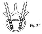
本発明のなお別の実施形態は、骨の回復のためのシステムに関し、このシステムは、少なくとも1つの拡張可能な移植物を備え得、この拡張可能な移植物は、骨の回復面に対応するための1つの拡張面を有する(1つ以上の移植物が、1つの骨において使用されて、より対称的な骨の回復を生じ得る;図37を参照のこと)。このシステムはまた、回復するための骨の外側表面に隣接して配置されるための第一の管、およびこの骨の内側の遠位端に固定するためのねじ切りされた端部を有する第一の棒を備え得る(この第一の棒は、この第一の管の内部に受容され得る)。このシステムはまた、第一の管を内部に受容するための第二の管、およびこの第二の管を受容するための第三の管を備え得る。この第三の管は、骨の外側表面にこの第三の管を係留するための、1つ以上の係合手段を備え得る。このシステムは、骨の側部に細長開口部を作製するためのドリルをさらに備え得、このドリルは、第一の棒によって案内され得る。さらに、このシステムは、拡張可能な移植物を患者に挿入するための、医療用挿入デバイスをさらに備え得る。 Yet another embodiment of the invention relates to a system for bone recovery, the system may comprise at least one expandable implant, the expandable implant corresponding to a bone recovery surface. (One or more implants can be used in one bone to produce a more symmetrical bone recovery; see FIG. 37). The system also includes a first tube for placement adjacent to the outer surface of the bone for recovery, and a threaded end for securing to the inner distal end of the bone. (The first rod may be received within the first tube). The system may also include a second tube for receiving the first tube therein and a third tube for receiving the second tube. The third tube may comprise one or more engagement means for anchoring the third tube to the outer surface of the bone. The system can further comprise a drill for creating an elongated opening in the side of the bone, which can be guided by a first rod. Furthermore, the system may further comprise a medical insertion device for inserting the expandable implant into the patient.
本発明のなおさらに別の実施形態において、拡張可能な移植物を患者に挿入するための、医療用挿入デバイスが開示される。このデバイスは、中心ボアを有する把持部分、この中心ボアに収容される第一の管、およびこの第一の管に収容されるねじ切りされた棒を備え得、このねじ切りされた棒は、患者への挿入のために移植物を受容するための遠位端を備え得る。このデバイスはまた、把持部分および/または移植物キャリアに取り付けられたハンドル、ならびにこの移植物の拡張を決定するためのゲージを備え得る。 In still yet another embodiment of the present invention, a medical insertion device for inserting an expandable implant into a patient is disclosed. The device may comprise a grasping portion having a central bore, a first tube received in the central bore, and a threaded rod received in the first tube, the threaded rod being attached to the patient. A distal end may be provided for receiving the implant for insertion. The device may also comprise a handle attached to the gripping portion and / or the implant carrier and a gauge for determining the expansion of the implant.
本発明のなお他の特徴、利点、実施形態および目的は、添付の図面および以下の詳細な説明を参照すると、さらにより明瞭になる。図面の簡単な説明は、以下に記載される。 Still other features, advantages, embodiments and objects of the present invention will become more apparent with reference to the accompanying drawings and the following detailed description. A brief description of the drawings is described below.
(実施形態の詳細な説明)
図1A〜図7に示される拡張可能な移植物1(および他の実施形態)は、以下のうちの1つ以上を備え得る:
・ その移植物に固有であり得る、1つの所定の拡張面2、
・ 拡張可能な移植物を位置決めして、拡張面を骨の回復面に対応させるための手段3、
・ 1つの拡張面2において、拡張可能な移植物を展開するための手段4、
・ 移植物のあらゆる拡張の前の移植物の最小の厚さAと、移植物の最大の拡張後の移植物の最大の厚さBとの間で、所定の拡張値を制御するための手段5、ならびに
・ 骨においてそれぞれ第一の支持表面8および第二の支持表面9を形成し得る、対向する第一のプレート6および第二のプレート7であって、これらのプレートは、移植物1の拡張の間、1つの拡張面2に沿って互いから離れて移動するように適合されている、プレート。(Detailed description of embodiment)
The expandable implant 1 (and other embodiments) shown in FIGS. 1A-7 may comprise one or more of the following:
One
A means 4 for deploying an expandable implant on one
A means for controlling a predetermined expansion value between the minimum implant thickness A before any expansion of the implant and the maximum implant thickness B after maximum expansion of the implant; 5, and opposite first and
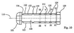
図1Aおよび図1Bに示されるように、移植物1は、横断方向の円形外側断面を有する、円筒形の形状を備え得、そして生体適合性材料(例えば、チタン)から、管状本体24に、旋盤加工技術、レーザー技術、および/または電気浸食製造技術を使用して、作製され得る(鋳造製造もまた、使用され得る)。移植物1はまた、第一の端部20および第二の端部21を備え得、これらの端部は、それぞれ、管状本体24の横断面の形状を呈する。これらの端部は、好ましくは、図1Bおよび図2Bに示されるように、この移植物の展開/拡張を可能にするように、互いの方へと動くように適合される。 As shown in FIGS. 1A and 1B, the
従って、2つの端部20、21は、第一の直線アーム22および第二の直線アーム23によって互いに接続され、これらのアームは、この移植物が展開されていない場合に、平行である。これらのアームは、管状本体24において、長手軸方向に形成され得る。すなわち、端部20および21が互いの方へと近付く際に折り畳まれ得、これはまた、管状本体の長手方向軸10から、対向する第一のプレート6および第二のプレート7の距離をとらせる。 Thus, the two ends 20, 21 are connected to each other by a first
図2A〜図2Bは、図1Aおよび図1Bに開示される実施形態と類似であるが、支持体のセット(例えば、4バーの連結)を加えた、移植物の1つの実施形態を図示する。より具体的には、図2A〜図2Bの移植物は、支持体13A、13B、14A、14B、15A、15B、16Aおよび16Bを備え、上のプレートと下のプレートとの各々に対して、2対の支持体を備える。さらなる支持体は、この移植物のためにさらなる剛性を提供し得、そして/またはプレート6および7が、実質的に平行かつ/または等間隔の様式で展開することを確実にし得る。 2A-2B illustrate one embodiment of an implant that is similar to the embodiment disclosed in FIGS. 1A and 1B, but adds a set of supports (eg, a 4 bar linkage). . More specifically, the implant of FIGS. 2A-2B comprises
図4〜図5に示されるように、アーム22および23が(管状本体24の長手方向軸10を通る)1つの面2内で展開するために、アーム22および23は、好ましくは、正反対側にある。この点に関して、アーム22および23は、管状本体24の横断凹部40から形成され得、この管状本体全体を横断し、そして移植物1の2つの端部20および21との間での、管状本体の長さにわたって延びる。図5に示されるように、アーム22、23は、それぞれ2つの端部20および21を接続し、管状本体24の外側表面の円弧26によって境界を定められる横断面を呈する。弦27は、円弧26を規定し、そして凹部40を形成するための壁25を備え得る。凹部40は、長手方向軸10に関して対称的であり得る。 As shown in FIGS. 4-5, in order for the
各アーム22、23は、3つの連続的な剛性部分に分割され得、これらの剛性部分は、(例えば)以下のように、端部20および21に関連して、一緒に関節運動し得る。上側のアーム22に関して、第一の剛性部分28は、関節29によって、一端にて端部20に接続される。剛性部分28の他端は、関節31によって、第二の隣接する剛性部分30の第一の端部に接続される。第二の剛性部分30は、関節33によって、第三の剛性部分32の第二の端部に接続され得る。第三の剛性部分32の他端は、関節34によって、端部21に接続され得る。好ましくは、関節29、31、33および34は、回転の1の自由度を有し得、それぞれ、拡張面2に対して垂直な軸の周りで作用する。好ましくは、関節29、31および33は、図1A〜図3に示されるように、関連する関節運動ゾーンにおいて、アームを形成する壁を薄くすることにより、形成される(例えば、参照番号5および81を参照のこと)。 Each
各アーム22、23は、展開され得、その結果、中心剛性部分30が、移植物の長手方向軸10から離れるように移動し、移植物の端部20および21互いの方へと動かされる場合に、2つの隣接する剛性部分28および32によって押される。図3により具体的に示されるように、端部20および21が互いの方へと動かされる場合に、アームの動きを正しい方向に制限する目的で、アームの種々の部分の適切な回転接続を確立することが好ましい。 Each
従って、上側のアーム22の端部28、32の剛性部分は、それぞれ、これらの剛性部分を形成する材料ウェブの下部において、端部20および21上で関節運動され得る。端部28、32の剛性部分はまた、剛性部分28、32を形成する材料ウェブの上側部分において、中心剛性部分30に対して関節運動され得る。端部20および21に力が付与されてこれらの端部をこの移植物の長手方向軸10に沿って一緒に動かす場合、関節運動の移動は、端部28および21の剛性部分の回転連結を確立する。この移動は、中心剛性部分30が長手方向軸10から離れて移動する結果として、剛性部分32を、移植物の外側の方へと旋回させる傾向がある。 Thus, the rigid portions of the ends 28, 32 of the
下側アーム23は、上側アームと類似の様式で構成され得、そして好ましくは、長手方向軸10を通る拡張面2に対して垂直な面に関して、上側アーム22と対称的である。 The
従って、本発明のいくつかの実施形態によれば、上側アーム22および下側アーム23の関節は、好ましくは、溝81によって提供される弱化ゾーンによって形成される。これらの溝は、管状本体24を形成する材料の薄いウェブ(すなわち、31、33における材料の厚さ)を規定し、この厚さは、この材料が破壊されることなく弾性変形することを可能にするように、(図に示されるように)溝81の深さによって決定され得る。具体的には、1つの実施形態によれば、上側アーム22のアーム28および32の剛性部分、ならびに下側アーム23におけるそれらに対称な部分は、過剰拡張と称される位置を呈し得、ここで、端部20および21が互いの方へと動く際に(端部21は、その最大拡張能力まで開く)、意図される剛性部分は、移植物1の長手方向軸10に対して垂直であり、対応する材料の可塑性変形を生じる。溝81の幅は、好ましくは、上側アームおよび下側アームの対のクリアランスを可能にするように、そしてまた、この材料の破壊なしで可塑性変形を確実にするために、ウェブの適切な曲率半径を与えるように、予め決定される。 Thus, according to some embodiments of the present invention, the joint of the
対向する第一のプレート6および第二のプレート7は、上側アーム22および下側アーム23に形成され得る。上側アーム22に関して、例えば、剛性プレート6は、中心剛性部分30によって、そしてこの部分の両側から延びる材料延長部(端部28および32)によって、形成され得る。剛性プレートを作製するために、端部28および32は、1対の横断スロット35および36を使用して、上側アーム22から分離される。これらの横断スロットは、各それぞれの端部の長さにわたって長手軸方向に延びる(図3〜4を参照のこと)。関節31および33、ならびに端部28および32は、それぞれ、第一のプレート6のための第一の支持体12および第二の支持体13を形成する。同じことが、対称にすることによって、第二のプレート7に対して適用される。 Opposing
従って、図示される実施形態によれば、第一のプレート6および第二のプレート7は、それぞれ、第一の片持ち梁ウィング16、18、および第二の片持ち梁ウィング17、19を備え得、これらのそれぞれの取り付けゾーンは、第一の支持体12、14および第二の支持体13、15と同じ高さに位置する。図1A〜3に示されるように、第一の片持ち梁ウィング16、18および第二の片持ち梁ウィング17、19は、1つの拡張面2における、第一のプレート5または第二のプレート7の一方の最大の移動値に実質的に対応する長さを有し得る。 Thus, according to the illustrated embodiment, the
第一のプレート6および第二のプレート7は、それぞれ、第一の支持表面8および第二の支持表面9を形成し、各々が、移植物の長さに実質的に等しくあり得る長さを有し、そして拡張の間、長手方向軸10に対して垂直に配置され得る。本発明の1つの実施形態によれば、移植物1は、管状本体24として形成されるので、第一のプレート6および第二のプレート7は、それぞれ、湾曲した表面を形成し、これらの表面は、それぞれ、長手方向軸10に対して平行である。 The
拡張可能な移植物を骨において位置決めして、拡張面2を骨の回復面に対応させるための手段3は、係合手段を備え得、この係合手段は、この移植物の、長手方向軸10の周りでの角配向を可能にする。例えば、このような手段は、第一の表面37、38を備え得、これらの表面は、端部の円形セクション20を有する円筒形表面上に形成され、これは、移植物1の回転係合を可能にし得る。拡張可能な移植物を、1つの拡張面2において展開するための手段4は、上側アーム22の端部28および32、ならびに下側アーム23の、対応する対称な端部を備え得、上側プレート6および下側プレート7の展開を可能にする。 The
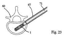
移植物キャリア71(図23を参照のこと)は、骨内に配置される場合に、この移植物の端部20および21が一緒に動くことを可能にするために、使用され得る。移植物キャリア71は、移植物の端部20を支持することによって、例えば、端部21が端部20の方へと引かれること、またはその逆(例えば、端部21が支持され、そして端部20が端部21の方に押される)を可能にする。この目的で、例えば、遠位端21は、移植物キャリア71(これは、対応するねじ切りされた部分を備える)の係合を可能にするための、長手方向軸10に沿ってねじ切りされたか移行部39を備える。近位端20は、移植物キャリア71のコアが遠位端21まで通ることを可能にするための、長手方向軸10に沿って、ボア80を備え得る。 An implant carrier 71 (see FIG. 23) can be used to allow the
制御手段5は、移植物キャリアによって提供され得、この手段は、端部20および21を一緒に動かすための、ミリメートルでの制御手段を備え得る。この制御は、好ましくは、螺合係合によってなされ、この拡張を、あらゆる瞬間において、必要に応じて停止させる。他方で、これらの制御手段はまた、アーム22および23の関節運動によって、より具体的には、各アームを規定する材料ウェブの厚さ(例えば、31、33)が、可塑性領域において変形し、アームの所定の展開位置を実質的に保存すること(事実上無視できる弾性収縮を除く)によって、提供される。 The control means 5 may be provided by an implant carrier, which means may comprise control means in millimeters for moving the
移植物のプレート6および7の拡張、およびそれらの安定性は、一旦展開されると、プレート6および7をこれらのプレートによって骨の幾何学的形状に適合させることによって、達成され得る。本発明のいくつかの実施形態においては、プレート6および7は、平行な配置で展開されるが、本発明の他の実施形態は、この移植物のプレート6および7が、必要に応じて、平行ではない(例えば、骨の解剖学的構造の関数として)移動で展開さえることを可能にする。例えば、プレート6および7の拡張は、個々の支持アームの長さが異なる場合には、平行ではないかもしれない。例えば、支持体12および14が、支持体13および15より長い場合(図1A〜図2Bを参照のこと)、この移植物の展開は、プレート6および7を、強制的に、次第に互いから離す。図1A〜図2Bにおいて、このことは、プレート6および7が、端部21において、端部20においてよりも互いから離れる結果となる。当業者が理解するように、構成に依存して、1つのみの代表的な支持体が、特定の角度を得るために、延長/短縮される必要がある。 Expansion of the
同様に、図2A〜図2Cに示されるように、支持体12A、12B、13A、13B、14A、14B、14Aおよび14Bを備える4バーの連結が、示されるように、等しい長さである場合(すなわち、12Aの長さ=13Aの長さ、12Bの長さ=13Bの長さ、など)、この移植物の拡張の際に、平行四辺形が生じる(平行四辺形は、線分ADとBCとの間に形成される)。L1およびL2の長さを改変することによって、4バーの連結は、拡張の際に平行四辺形を生じず、むしろ、プレート6と8との間に角度が生じる。形成される角度はまた、端部20と21と外貨に接近して互いの近くに引かれるかに依存し得る。移植物が展開されると、この角度は、次第に増加する。 Similarly, as shown in FIGS. 2A-2C, when a four bar connection comprising supports 12A, 12B, 13A, 13B, 14A, 14B, 14A and 14B is of equal length, as shown (Ie, 12A length = 13A length, 12B length = 13B length, etc.), upon expansion of the implant, a parallelogram is formed (a parallelogram is defined as a line segment AD and Formed with BC). By modifying the lengths of L1 and L2, the four bar connection does not produce a parallelogram upon expansion, but rather an angle between the
図8〜図16は、拡張可能な移植物101の第二の実施形態に関し、この移植物の要素は、図1〜図7に図示された移植物の実施形態の対応する要素と機能的に類似である。さらに、図8〜図16における対応する図は、図1〜図7に図示される実施形態に関連して、100を加えられたそれぞれ同じ参照番号を有し、従って、さらに記載されない。 FIGS. 8-16 relate to a second embodiment of the
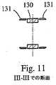
示される移植物101は、図9により具体的に示されるように、プレート106および107にウィング部が存在しないことが、移植物1と異なる。移植物101は、平行四辺形のシステム141を、アーム122および123の各々の端部128または132のうちの一方に備える。図示される実施例において、平行四辺形のシステムは、上側アーム122の端部128に提示され、端部120に接続され、そして対応するシステムが、下側アーム123に提示される。これらの平行四辺形のシステムは、アーム122および123の各々のプレートの、移植物の長手方向軸110に対して平行な移動を確実にするために、使用され得る。図に示されるように、アーム122の端部128は(対応するアーム123と同様に)、移植物の中心部分130および端部120にわたって(それぞれ)関節131および129と同様に分離しており、これによって、対応するプレートの移動の間に変形可能な平行四辺形を形成する。 The
変形可能な平行四辺形141の関節運動は、図8〜16に示されるように、アーム122の他の関節131、133、134と同じ様式で生じ得る。上で説明され、そして図11〜14に表されるような、開示される幾何学的形状は、アームの種々の部分129、130、132に対する力の結合を確立する。このことは、移植物101の端部120および121を一緒に動かす場合に、所望の移動を可能にする。 The articulation of the
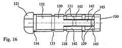
変形可能な平行四辺形141を得る目的で、アームの端部128は、好ましくは、3つの長手軸方向レバー(2つの横方向レバー142および1つの中心レバー143)に分割される。これらのレバーは、変形可能な平行四辺形141の2辺を形成する。この平行四辺形の残りの2つの辺は、アーム122の中心部分の延長部144(これは、中心レバー143の延長軸内に配置される)、および端部120の二重の延長部145(これは、移植物の長手方向軸110に対して平行に延び、そして2つの横方向レバー142の延長軸内に配置される)によって形成され得る(図8を参照のこと)。 In order to obtain a
アーム122および123は、移植物101の長手方向軸110を通る延長面102に対して実質的に垂直な面に関して、対称であり得、これによって、この移植物の拡張の間、2つのプレート106および107の移動は、長手方向軸110に対して平行な様式であることに注目することは、価値がある。 The
(骨の回復の実施例)
本発明の1つの実施形態に従って、拡張可能な移植物を使用して、ヒトの骨を回復させるための方法の第一の例を、ここで図17〜29を参照して記載する。この実施例は、より具体的には、骨折の整復を伴う、後外側の経路を介しての椎骨の骨回復のための方法に関する。従って、この方法は、以下の工程のうちの1つ以上(そして好ましくは、全て)を包含し得る。当業者は、本発明のこのような実施形態に従う移植物が、骨の内部の組織を押し/分割し、その結果、移植物の負担表面が、好ましくは、回復のための骨組織と接触することを理解する。(Example of bone recovery)
In accordance with one embodiment of the present invention, a first example of a method for restoring human bone using an expandable implant will now be described with reference to FIGS. This example more specifically relates to a method for bone recovery of the vertebrae via the posterior-lateral path with fracture reduction. Thus, the method can include one or more (and preferably all) of the following steps. One skilled in the art will recognize that an implant according to such an embodiment of the present invention will push / split the tissue inside the bone so that the bearing surface of the implant is preferably in contact with the bone tissue for recovery. I understand that.
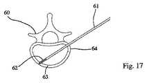
1つの規定された面2において(好ましくは)拡張可能である、拡張可能な移植物が、椎骨60に導入され、この椎骨の形状が、回復される。この操作を行うためには、棒/ピン61(例えば、Kirschnerピン型)が、後外側経路を介して皮下に配置され、その結果、ねじ切りされた端部62が、ピンで貫通される皮質骨64の反対側で、皮質骨63内に固定され得る(例えば、ねじ込まれ得る)(図17)。ピン61は、第一の管65の端部が皮質骨64の外側表面と接触する(例えば、支持され得る)まで、第一の拡大管65内に受容される(図18)。 An expandable implant that is (preferably) expandable in one defined
第一の拡大管65は、第二の管66の端部が皮質骨64の外側表面に接触する(例えば、支持される)まで、第二の拡大管66によって受容される(図19)。第二の拡大管は、第三の拡大管67によってさらに受容され、この第三の拡大管は、皮質骨64の外側表面に接触する(例えば、支持される)(図20)。第三の拡大管67の端部の歯68が、皮質骨64内にこの管を係留する。 The
次いで、第一の拡大管65および第二の拡大管66は、図21に示されるように、取り外され、管67によって囲まれるピン61のみを残し、これらは、管状スペーサー68によって、互いから分離される。次いで、近位皮質骨64および海綿質70は、図22に示されるように、(例えば)ピン61によって案内されるドリル69によって穿孔される。1つの実施形態において、この海綿質は、(およそ)最も遠位の3分の1が穿孔され、次いで、ドリル69は、引き抜かれ得る(ピン61が同様に引き抜かれ得る)。 The
移植物1の近位端は、(好ましくは)移植物キャリア71の中空コアの遠位端に取り外し可能に取り付けられ、このキャリアは、次いで、図23に示されるように、管67のコアに導入される。この移植物は、(例えば)螺合係合を介して、移植物キャリアに取り外し可能に固定され得る。移植物キャリア71のコアの内部には、遠位端を有する棒3316が挿入され得る。この遠位端は、移植物の遠位端を係合するための係合手段を備える(そしてまた、棒の直径より大きい拡張した近位端を備え得る)。移植物キャリアへの移植物の固定と同様に、この移植物へのこの棒の係合手段は、螺合係合を介し得る。 The proximal end of the
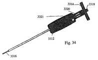
移植物キャリア71は、図33に示されるように、(例えば)この移植物キャリアに対する棒の動きを制御するための、ハンドリング手段3310を備える。このハンドリング手段は、中心ボアを有する把持ブロック3312を備え得、この中心ボアを通して、移植物キャリア71が配置され、そして少なくとも回転可能であるが好ましくは回転可能かつ線形運動可能に、適所に保持される。この点に関して、把持部材の近位端および移植物キャリアの近位端は、好ましくは、同一面にある。ハンドル3314は、本発明の1つの実施形態によれば、把持部材および移植物キャリアのいずれかまたは両方の近位端に取り付けられ得るが、好ましくは、時計回り方向および反時計回り方向のいずれかまたは両方で、これらに対して自由に回転する。本発明のなお別の実施形態において、このハンドルは、把持ブロックおよび移植物キャリアのいずれかにも両方にも取り付けられないかもしれない。このハンドルは、中心開口部を備え得、この開口部は、好ましくは、所定のねじ山ピッチのめねじのねじ山を備える。 The
移植物キャリアの内部に受容される棒3316は、好ましくは、ハンドル3314のねじ山ピッチに対応するおねじを備える。ロックデバイス3311は、把持ブロックに対してスライドし、そしてピン3321を備え得る。このピン3321は、棒3316と摩擦により干渉して、この棒を適所にロックする(すなわち、回転運動しない)。 The
棒のねじ山は、好ましくは、少なくともこの棒の長さの大部分に沿って提供される。本発明の1つの実施形態によれば、棒、移植物キャリア、把持ブロックおよびハンドルは、予め組み立てられ得る。この棒のねじ切りされた遠位端を、移植物の近位端の中心の開口部に挿入し、次いで、この棒は、この移植物の遠位端の中心の、対応するねじ切りされた部分に受容され得る。次いで、移植物と移植物キャリア/ハンドリング手段とのアセンブリの遠位端(すなわち、移植物の位置)は、拡大管67に挿入され得る。 The thread of the bar is preferably provided at least along most of the length of the bar. According to one embodiment of the invention, the rod, implant carrier, grasping block and handle can be pre-assembled. The threaded distal end of the rod is inserted into the central opening of the proximal end of the implant, and then the rod is inserted into the corresponding threaded portion of the center of the distal end of the implant. Can be accepted. The distal end of the implant and implant carrier / handling means assembly (ie, the position of the implant) can then be inserted into the
図34は、移植物キャリアの別の図を図示し、そして移植物の拡張の量を示す(例えば、棒3316の回転の量の決定)ために使用され得る、ゲージ3320を備える。このゲージは、棒3316に対する窓を備え得る。図35に示されるように、本発明の1つの実施形態によれば、棒の見える部分は、ねじ山を備えないかもしれない。むしろ、棒のこのセクションは、マーク3322を備え得、このマークが、拡張の百分率を示す。窓に隣接して提供されるさらなるマーク3324は、使用者が、拡張の百分率を、2つのマークの間の相対運動から測ることを可能にする。 FIG. 34 includes a
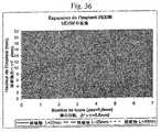
棒3316の所定のねじ山ピッチおよびねじ山の方向に依存して、ハンドルの回転は、棒3316を移植物キャリアに対して、ある方向に線状に移動させる。好ましくは、これらのねじ山は、ハンドルの時計回りの回転が、この棒を外向きに移動させて、移植物が拡張される領域(移植領域)から離すように、提供される。例えば、M5のねじについて、0.8mmのピッチが使用され得る。しかし、当業者は、(例えば)約0.5mmと約1.0mmとの間のねじ山ピッチが使用され得ることを理解する。図36は、3つの特定のサイズの移植物についての、この棒の回転の回数による、本発明の実施形態の1つによる移植物の、付加のない拡張を図示する図である。 Depending on the predetermined thread pitch and thread direction of the
従って、上記実施形態を考慮して、一旦、移植物が拡大管内に配置されると、この管の内部に沿ってスライドされ、椎骨60の内部に配置される。この移植物は、好ましくは、1つの拡張面2が、望ましい骨の回復面に対応するように位置決めされる(図24)。この移植物の位置は、任意の公知の画像化技術(例えば、X線および超音波が挙げられる)を使用して、確認され得る。 Thus, in view of the above embodiment, once the implant is placed in the enlarged tube, it is slid along the inside of the tube and placed inside the
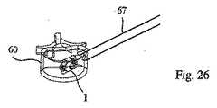
次いで、ハンドル3314は、回転されて、この棒を移植領域から「引き」離す。移植物の近位端は、移植物キャリアに突き当たるので、この棒を引くことにより、この移植物の遠位端は、近位端の方へと移動する(またはその逆である)。この結果として、移植物の端部は、互いの方へと引かれ、これにより、移植物を開く。より具体的には、対向するプレート6および7が展開され、それぞれ、第一の支持表面8および第二の支持表面9を、椎骨60の内部に有利に形成し、これらの表面は、それらの長さにわたって連続的であり得、この長さは、移植物1の長さに実質的に等しくあり得る(図25)。この拡張の経過において、骨折の整復の制御がなされる。 The
従って、椎骨内での移植物の拡張は、プレートの下方の支持体によって達成され、押し付ける力が、この支持体の下方のプレートの長さにわたって分配される。従って、十分な長さのプレートが提供され得、一方で、撓みに抵抗するために、このプレートの厚さの過剰の寸法が制限される。本発明のいくつかの実施形態による移植物は、長さの空間的要件(非拡張)対上昇プレートの長さの、極度に最適化される比を呈し、例えば、骨折の整復の観点で、制限された骨内空間の好ましい使用を可能にすることが、当業者によって理解される。 Thus, the expansion of the implant within the vertebra is achieved by the support below the plate, and the pressing force is distributed over the length of the plate below this support. Thus, a sufficiently long plate can be provided, while limiting the excessive dimension of the plate thickness to resist deflection. An implant according to some embodiments of the present invention exhibits a highly optimized ratio of length spatial requirements (non-expanded) to length of the rising plate, e.g. in terms of fracture reduction, It will be appreciated by those skilled in the art that it allows the preferred use of limited intraosseous space.
棒3316はまた、本発明の実施形態の1つによれば、脱係合手段を備え得、この手段は、この棒の近位端3318の内部六角形を備え得る。これにより、一旦、この移植物が展開されると、この棒を移植物から脱係合させることが可能になり得る。あるいは、ハンドルが、把持ブロックおよび/または移植物キャリアに取り付けられない場合、このハンドルは、逆方向に回転され得(すなわち、棒が移植物から離れる方向に移動しないように回転され得)、その結果、このハンドルは、把持ブロックおよび移植物キャリアの同一面部分から離れるように移動し、その結果、このハンドルは、この棒の近位端に係合する。このハンドルをさらに(移植物の展開後に)逆回転させると、この棒は、このハンドルと同じく逆回転し、これによって、この棒が、この移植物から脱係合する。所定のねじ山ピッチに依存して、このような脱係合は、任意の回転数(例えば、1回転以下)でなされ得る。図26もまた参照のこと。 The
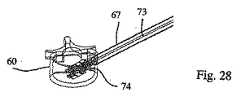
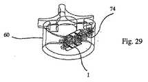
好ましくは、この棒が取り外された後に、充填材料74が、移植物の周囲に注入される。この充填材料は、例えば、イオン性セメントを含有し得、特に、移植物の内部および周囲を充填する観点から、リンカルクセメント、アクリルセメント、またはアクリルセメントの化合物を含有し得る。このことを達成するために、注入器73の針が、この針の端部が移植物1の遠位オリフィス39に達するまで、管67に沿ってスライドされる(図27)。次いで、この充填材料は、この針を介して注入される。逆方向の様式での連続注入は、椎骨60の近位オリフィス64までなされ得る(図28)。次いで、この注入器の針は、管67から引き抜かれ得る(図29)。 Preferably, after the rod is removed,
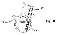
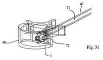
本発明の実施形態による、ヒトの骨の解剖学的構造の回復のための方法の第二の例が、ここで図30〜図32を参照して記載される。この実施例は、一般に、骨折の整復を伴う、経茎経路による、椎骨の骨回復のための方法に関する。 A second example of a method for recovery of human bone anatomy according to embodiments of the present invention will now be described with reference to FIGS. This example generally relates to a method for vertebral bone recovery via the transpedicular route with fracture reduction.
この第二の実施例は、第一の実施例と類似であり、そして椎骨60内への移植物の経茎経路が、第一の実施形態とは異なる。この経路は、ここで、第一の方法において使用された後外側経路の代わりに、経茎の様式(図30)で達成される。従って、移植物1を椎骨に導入するために使用される異なる経路を示すために、第二の方法のうちのいくつかの工程のみが、図30〜図32に提供される。図30から図32について、第一の方法の実施例の要素と同じ要素は、同じ参照番号を有し、そしてこれらの図は、それぞれ、第一の方法の実施例の図24、図25、および図28の工程に対応する。図32に示される工程に関して、後者は、注入器73の針を、図32において、移植物の遠位端のより近くに配置することにより、図28とはわずかに異なる。 This second example is similar to the first example and the transpedicular pathway of the implant into the
従って、本発明は、先行する記載から明らかになる目的を達成することが分かる。特定の変化が、本発明の範囲から逸脱することなくなされ得るので、上記説明に含まれるか、または添付の図面に示される全ての事項は、例示として解釈され、そして文字通りの意味では解釈されない(従って、限定されない)ことが、意図される。当業者は、本明細書中に図示および記載された方法、デバイスおよびシステムの構成が、本発明の範囲に入る複数の可能なシステム構成の例であることを認識する。 Thus, it can be seen that the present invention achieves the objects that will become apparent from the preceding description. Since certain changes may be made without departing from the scope of the invention, all matter contained in the above description or shown in the accompanying drawings is to be interpreted as illustrative and not in a literal sense ( Thus, it is intended to be non-limiting). Those skilled in the art will recognize that the method, device and system configurations illustrated and described herein are examples of multiple possible system configurations that fall within the scope of the present invention.
Claims (17)
Translated fromJapanese該移植物に固有の、1つの拡張面であって、該1つの拡張面は、骨の回復面に対応する、拡張面;
該骨のための、第一の負担表面および第二の負担表面をそれぞれ形成する、対向する第一のプレートおよび第二のプレートであって、該第一のプレートおよび第二のプレートは、該移植物の拡張の際に、該1つの拡張面に沿って互いから離れて移動するために適している、第一のプレートおよび第二のプレート;
該第一の負担表面および第二の負担表面の各々のための、第一の支持体および第二の支持体であって、それぞれ、第一のプレートおよび第二のプレートの下方に位置する、第一の支持体および第二の支持体;ならびに
該移植物の拡張を制御するための手段であって、該手段は、各支持体と対応するプレートとの間に提供される材料ウェブを備え、該移植物の拡張を制御する所定の厚さを有する、手段、
を備える、拡張可能な移植物。An expandable implant for bone recovery, the following:
An expansion surface inherent to the implant, the expansion surface corresponding to a bone recovery surface;
Opposing first and second plates forming a first bearing surface and a second bearing surface, respectively, for the bone, wherein the first plate and the second plate are A first plate and a second plate suitable for moving away from each other along the one expansion plane during expansion of the implant;
A first support and a second support for each of the first bearing surface and the second bearing surface, respectively located below the first plate and the second plate; A first support and a second support; and means for controlling expansion of the implant, the means comprising a material web provided between each support and a corresponding plate Means having a predetermined thickness for controlling expansion of the implant;
An expandable implant comprising:
中心ボアを有する把持部分;
該中心ボアに収容される第一の管;
該第一の管に収容されるねじ切りされた棒であって、該患者への挿入のために、移植物を受容するための遠位端を有する、ねじ切りされた棒;
該把持部分および/または該移植物キャリアに取り付けられた、ハンドル;ならびに
該移植物の拡張を決定するためのゲージ、
を備える、デバイス。A medical insertion device for inserting an expandable implant into a patient, comprising:
A gripping portion having a central bore;
A first tube received in the central bore;
A threaded rod housed in the first tube, the threaded rod having a distal end for receiving an implant for insertion into the patient;
A handle attached to the grip portion and / or the implant carrier; and a gauge for determining expansion of the implant;
A device comprising:
少なくとも1つの拡張可能な移植物であって、骨の回復面に対応する1つの拡張面を有する、拡張可能な移植物;
回復させる骨の外側表面に隣接して位置するための、第一の管;
該骨の内部の遠位端に固定するためにねじ切りされた端部を有する第一の棒であって、該第一の棒は、該第一の管に受容される、第一の棒;
該第一の管を内部に受容するための第二の管;
該第二の管を受容するための第三の管であって、該第三の管は、該第三の管を該骨の外側表面に係留するための1つ以上の係合部材を備える、第三の管;
該骨の側面に細長開口部を作製するためのドリルであって、該ドリルは、該第一の棒によって案内される、ドリル;および
拡張可能な移植物を患者に挿入するための、医療用挿入デバイス、
を備える、システム。A system for bone recovery comprising:
At least one expandable implant having one expandable surface corresponding to the bone recovery surface;
A first tube for positioning adjacent to the outer surface of the bone to be restored;
A first rod having a threaded end for securing to the interior distal end of the bone, the first rod being received in the first tube;
A second tube for receiving the first tube therein;
A third tube for receiving the second tube, the third tube comprising one or more engagement members for anchoring the third tube to the outer surface of the bone; A third tube;
A drill for creating an elongated opening in the side of the bone, the drill being guided by the first rod; and a medical for inserting an expandable implant into a patient Insertion device,
A system comprising:
中心ボアを有する把持部分;
該中心ボアに収容される第四の管;
前記第一の管に収容される第二の棒であって、該第二の棒は、前記患者への挿入のために移植物を受容するための遠位端を有し、そしてねじ切りされている、第二の棒;
該把持部分および/または該移植物キャリアに取り付けられた、ハンドル;ならびに
該移植物の拡張を決定するためのゲージ、
を備える、請求項14に記載のシステム。The medical insertion device is:
A gripping portion having a central bore;
A fourth tube received in the central bore;
A second rod received in the first tube, the second rod having a distal end for receiving an implant for insertion into the patient and threaded; The second rod;
A handle attached to the grip portion and / or the implant carrier; and a gauge for determining expansion of the implant;
15. The system of claim 14, comprising:
1つの拡張面を有する拡張可能な移植物を、骨に導入する工程;
該1つの所定の面を骨の回復面と一致させるように、該拡張可能な移植物を、該骨の内部で位置決めする工程;
該骨の回復面内で該移植物を拡張させる工程であって、第一の支持表面および第二の支持表面が、該骨の内部の組織を広げる、工程;ならびに
該移植物の周囲に充填材料を注入する工程、
を包含する、方法。A method for restoring the anatomy of a human or animal bone comprising:
Introducing an expandable implant having one expansion surface into the bone;
Positioning the expandable implant within the bone such that the one predetermined surface coincides with a bone recovery surface;
Expanding the implant within the bone recovery surface, the first and second support surfaces expanding tissue within the bone; and filling around the implant Injecting material,
Including the method.
Applications Claiming Priority (3)
| Application Number | Priority Date | Filing Date | Title |
|---|---|---|---|
| FR0406211AFR2871366A1 (en) | 2004-06-09 | 2004-06-09 | PROSTHETIC EXPANSIBLE BONE IMPLANT |
| US10/951,766US20050278036A1 (en) | 2004-06-09 | 2004-09-29 | Method for restoration of human or animal bone anatomy, and expansible prosthetic implant allowing implementation of this method |
| PCT/IB2005/002631WO2005120400A2 (en) | 2004-06-09 | 2005-06-08 | Methods and apparatuses for bone restoration |
Related Child Applications (1)
| Application Number | Title | Priority Date | Filing Date |
|---|---|---|---|
| JP2010174886ADivisionJP5508182B2 (en) | 2004-06-09 | 2010-08-03 | Method and apparatus for bone recovery |
Publications (3)
| Publication Number | Publication Date |
|---|---|
| JP2008501462Atrue JP2008501462A (en) | 2008-01-24 |
| JP2008501462A5 JP2008501462A5 (en) | 2008-06-19 |
| JP4620120B2 JP4620120B2 (en) | 2011-01-26 |
Family
ID=34945793
Family Applications (3)
| Application Number | Title | Priority Date | Filing Date |
|---|---|---|---|
| JP2007526606AExpired - LifetimeJP4620120B2 (en) | 2004-06-09 | 2005-06-08 | Method and apparatus for bone recovery |
| JP2010174886AExpired - LifetimeJP5508182B2 (en) | 2004-06-09 | 2010-08-03 | Method and apparatus for bone recovery |
| JP2012286471APendingJP2013078639A (en) | 2004-06-09 | 2012-12-28 | Method and apparatus for bone restoration |
Family Applications After (2)
| Application Number | Title | Priority Date | Filing Date |
|---|---|---|---|
| JP2010174886AExpired - LifetimeJP5508182B2 (en) | 2004-06-09 | 2010-08-03 | Method and apparatus for bone recovery |
| JP2012286471APendingJP2013078639A (en) | 2004-06-09 | 2012-12-28 | Method and apparatus for bone restoration |
Country Status (12)
| Country | Link |
|---|---|
| US (6) | US20050278036A1 (en) |
| EP (2) | EP2572680B1 (en) |
| JP (3) | JP4620120B2 (en) |
| KR (1) | KR101206552B1 (en) |
| CN (2) | CN101031259A (en) |
| AU (1) | AU2005251536B2 (en) |
| CA (1) | CA2567274C (en) |
| ES (2) | ES2576291T3 (en) |
| FR (2) | FR2871366A1 (en) |
| MX (2) | MXPA06014196A (en) |
| PL (1) | PL1778136T4 (en) |
| WO (1) | WO2005120400A2 (en) |
Cited By (11)
| Publication number | Priority date | Publication date | Assignee | Title |
|---|---|---|---|---|
| JP2012513242A (en)* | 2008-12-22 | 2012-06-14 | ジンテス ゲゼルシャフト ミット ベシュレンクテル ハフツング | Expandable vertebral body replacement system and method |
| JP2012520108A (en)* | 2009-03-12 | 2012-09-06 | ヴェクシム エセアー | Apparatus and method of use for spinal bone repair |
| JP2013537047A (en)* | 2010-07-15 | 2013-09-30 | エヌエルティー スパイン エルティーディー. | Surgical system and method for implanting expandable implants |
| JP2014073405A (en)* | 2013-12-20 | 2014-04-24 | Vexim Sa | Apparatus and usage for bone restoration of vertebra |
| JP2015536773A (en)* | 2012-12-14 | 2015-12-24 | ファセット−リンク・インコーポレイテッドFacet−Link Inc. | Intervertebral fusion implant with large vertical adjustment |
| US9408707B2 (en) | 2004-06-09 | 2016-08-09 | Vexim Sa | Methods and apparatuses for bone restoration |
| US9414933B2 (en) | 2011-04-07 | 2016-08-16 | Vexim Sa | Expandable orthopedic device |
| US9579130B2 (en) | 2008-04-08 | 2017-02-28 | Vexim Sas | Apparatus for restoration of the spine and methods of use thereof |
| US10603080B2 (en) | 2013-12-23 | 2020-03-31 | Vexim | Expansible intravertebral implant system with posterior pedicle fixation |
| JP2021074488A (en)* | 2019-11-05 | 2021-05-20 | ウィルトロム カンパニー, リミテッドWiltrom Co., Ltd. | Spinal implant structure |
| JP2023535765A (en)* | 2020-07-27 | 2023-08-21 | エイエム・ソリューションズ・ホールディング・ベスローテン・フエンノートシャップ | Expandable implants, implant systems, kits of parts for assembling expandable implants, and methods of placing implants in bone |
Families Citing this family (338)
| Publication number | Priority date | Publication date | Assignee | Title |
|---|---|---|---|---|
| US7959652B2 (en)* | 2005-04-18 | 2011-06-14 | Kyphon Sarl | Interspinous process implant having deployable wings and method of implantation |
| US6068630A (en)* | 1997-01-02 | 2000-05-30 | St. Francis Medical Technologies, Inc. | Spine distraction implant |
| US8128661B2 (en)* | 1997-01-02 | 2012-03-06 | Kyphon Sarl | Interspinous process distraction system and method with positionable wing and method |
| US7201751B2 (en) | 1997-01-02 | 2007-04-10 | St. Francis Medical Technologies, Inc. | Supplemental spine fixation device |
| US20080086212A1 (en)* | 1997-01-02 | 2008-04-10 | St. Francis Medical Technologies, Inc. | Spine distraction implant |
| US6695842B2 (en)* | 1997-10-27 | 2004-02-24 | St. Francis Medical Technologies, Inc. | Interspinous process distraction system and method with positionable wing and method |
| US20080039859A1 (en)* | 1997-01-02 | 2008-02-14 | Zucherman James F | Spine distraction implant and method |
| US7306628B2 (en)* | 2002-10-29 | 2007-12-11 | St. Francis Medical Technologies | Interspinous process apparatus and method with a selectably expandable spacer |
| CA2363254C (en) | 1999-03-07 | 2009-05-05 | Discure Ltd. | Method and apparatus for computerized surgery |
| FR2828398B1 (en)* | 2001-08-08 | 2003-09-19 | Jean Taylor | VERTEBRA STABILIZATION ASSEMBLY |
| US7097665B2 (en)* | 2003-01-16 | 2006-08-29 | Synecor, Llc | Positioning tools and methods for implanting medical devices |
| DE10154163A1 (en)* | 2001-11-03 | 2003-05-22 | Advanced Med Tech | Device for straightening and stabilizing the spine |
| US8317798B2 (en)* | 2002-06-25 | 2012-11-27 | Warsaw Orthopedic | Minimally invasive expanding spacer and method |
| US6793678B2 (en) | 2002-06-27 | 2004-09-21 | Depuy Acromed, Inc. | Prosthetic intervertebral motion disc having dampening |
| CN100584294C (en)* | 2002-08-27 | 2010-01-27 | 华沙整形外科股份有限公司 | System for intravertebral reduction |
| FR2844179B1 (en)* | 2002-09-10 | 2004-12-03 | Jean Taylor | POSTERIOR VERTEBRAL SUPPORT KIT |
| US7931674B2 (en)* | 2005-03-21 | 2011-04-26 | Kyphon Sarl | Interspinous process implant having deployable wing and method of implantation |
| US20080021468A1 (en)* | 2002-10-29 | 2008-01-24 | Zucherman James F | Interspinous process implants and methods of use |
| US20060264939A1 (en)* | 2003-05-22 | 2006-11-23 | St. Francis Medical Technologies, Inc. | Interspinous process implant with slide-in distraction piece and method of implantation |
| US7549999B2 (en)* | 2003-05-22 | 2009-06-23 | Kyphon Sarl | Interspinous process distraction implant and method of implantation |
| US8147548B2 (en) | 2005-03-21 | 2012-04-03 | Kyphon Sarl | Interspinous process implant having a thread-shaped wing and method of implantation |
| US8048117B2 (en) | 2003-05-22 | 2011-11-01 | Kyphon Sarl | Interspinous process implant and method of implantation |
| US8070778B2 (en)* | 2003-05-22 | 2011-12-06 | Kyphon Sarl | Interspinous process implant with slide-in distraction piece and method of implantation |
| AU2004212942A1 (en) | 2003-02-14 | 2004-09-02 | Depuy Spine, Inc. | In-situ formed intervertebral fusion device |
| US20040267367A1 (en) | 2003-06-30 | 2004-12-30 | Depuy Acromed, Inc | Intervertebral implant with conformable endplate |
| WO2005027734A2 (en)* | 2003-09-19 | 2005-03-31 | Synecor, Llc | Method and apparatus for treating diseased or fractured bone |
| US8636802B2 (en) | 2004-03-06 | 2014-01-28 | DePuy Synthes Products, LLC | Dynamized interspinal implant |
| US7585316B2 (en)* | 2004-05-21 | 2009-09-08 | Warsaw Orthopedic, Inc. | Interspinous spacer |
| US8236029B2 (en) | 2004-08-11 | 2012-08-07 | Nlt Spine Ltd. | Devices for introduction into a body via a substantially straight conduit to for a predefined curved configuration, and methods employing such devices |
| WO2006034436A2 (en)* | 2004-09-21 | 2006-03-30 | Stout Medical Group, L.P. | Expandable support device and method of use |
| US8152837B2 (en) | 2004-10-20 | 2012-04-10 | The Board Of Trustees Of The Leland Stanford Junior University | Systems and methods for posterior dynamic stabilization of the spine |
| US8167944B2 (en) | 2004-10-20 | 2012-05-01 | The Board Of Trustees Of The Leland Stanford Junior University | Systems and methods for posterior dynamic stabilization of the spine |
| US9023084B2 (en) | 2004-10-20 | 2015-05-05 | The Board Of Trustees Of The Leland Stanford Junior University | Systems and methods for stabilizing the motion or adjusting the position of the spine |
| US8317864B2 (en) | 2004-10-20 | 2012-11-27 | The Board Of Trustees Of The Leland Stanford Junior University | Systems and methods for posterior dynamic stabilization of the spine |
| US8409282B2 (en) | 2004-10-20 | 2013-04-02 | Vertiflex, Inc. | Systems and methods for posterior dynamic stabilization of the spine |
| US7763074B2 (en) | 2004-10-20 | 2010-07-27 | The Board Of Trustees Of The Leland Stanford Junior University | Systems and methods for posterior dynamic stabilization of the spine |
| US9161783B2 (en) | 2004-10-20 | 2015-10-20 | Vertiflex, Inc. | Interspinous spacer |
| US8128662B2 (en) | 2004-10-20 | 2012-03-06 | Vertiflex, Inc. | Minimally invasive tooling for delivery of interspinous spacer |
| US8425559B2 (en) | 2004-10-20 | 2013-04-23 | Vertiflex, Inc. | Systems and methods for posterior dynamic stabilization of the spine |
| US8273108B2 (en) | 2004-10-20 | 2012-09-25 | Vertiflex, Inc. | Interspinous spacer |
| US8123807B2 (en)* | 2004-10-20 | 2012-02-28 | Vertiflex, Inc. | Systems and methods for posterior dynamic stabilization of the spine |
| US9119680B2 (en) | 2004-10-20 | 2015-09-01 | Vertiflex, Inc. | Interspinous spacer |
| US8597360B2 (en) | 2004-11-03 | 2013-12-03 | Neuropro Technologies, Inc. | Bone fusion device |
| EP2219538B1 (en) | 2004-12-06 | 2022-07-06 | Vertiflex, Inc. | Spacer insertion instrument |
| US8100943B2 (en) | 2005-02-17 | 2012-01-24 | Kyphon Sarl | Percutaneous spinal implants and methods |
| US7988709B2 (en)* | 2005-02-17 | 2011-08-02 | Kyphon Sarl | Percutaneous spinal implants and methods |
| US20070055237A1 (en)* | 2005-02-17 | 2007-03-08 | Edidin Avram A | Percutaneous spinal implants and methods |
| US8029567B2 (en)* | 2005-02-17 | 2011-10-04 | Kyphon Sarl | Percutaneous spinal implants and methods |
| US20080039944A1 (en)* | 2005-02-17 | 2008-02-14 | Malandain Hugues F | Percutaneous Spinal Implants and Methods |
| US20080288078A1 (en)* | 2005-02-17 | 2008-11-20 | Kohm Andrew C | Percutaneous spinal implants and methods |
| US8034080B2 (en) | 2005-02-17 | 2011-10-11 | Kyphon Sarl | Percutaneous spinal implants and methods |
| US20060184248A1 (en)* | 2005-02-17 | 2006-08-17 | Edidin Avram A | Percutaneous spinal implants and methods |
| US8157841B2 (en)* | 2005-02-17 | 2012-04-17 | Kyphon Sarl | Percutaneous spinal implants and methods |
| US8038698B2 (en)* | 2005-02-17 | 2011-10-18 | Kphon Sarl | Percutaneous spinal implants and methods |
| US20070276372A1 (en)* | 2005-02-17 | 2007-11-29 | Malandain Hugues F | Percutaneous Spinal Implants and Methods |
| US20070276493A1 (en) | 2005-02-17 | 2007-11-29 | Malandain Hugues F | Percutaneous spinal implants and methods |
| US8007521B2 (en)* | 2005-02-17 | 2011-08-30 | Kyphon Sarl | Percutaneous spinal implants and methods |
| US8097018B2 (en)* | 2005-02-17 | 2012-01-17 | Kyphon Sarl | Percutaneous spinal implants and methods |
| US7998174B2 (en) | 2005-02-17 | 2011-08-16 | Kyphon Sarl | Percutaneous spinal implants and methods |
| US8096994B2 (en) | 2005-02-17 | 2012-01-17 | Kyphon Sarl | Percutaneous spinal implants and methods |
| US8057513B2 (en)* | 2005-02-17 | 2011-11-15 | Kyphon Sarl | Percutaneous spinal implants and methods |
| US20060241757A1 (en)* | 2005-03-31 | 2006-10-26 | Sdgi Holdings, Inc. | Intervertebral prosthetic device for spinal stabilization and method of manufacturing same |
| US8940048B2 (en) | 2005-03-31 | 2015-01-27 | Life Spine, Inc. | Expandable spinal interbody and intravertebral body devices |
| US9034041B2 (en)* | 2005-03-31 | 2015-05-19 | Life Spine, Inc. | Expandable spinal interbody and intravertebral body devices |
| US9801733B2 (en) | 2005-03-31 | 2017-10-31 | Life Spine, Inc. | Expandable spinal interbody and intravertebral body devices |
| US7731751B2 (en)* | 2005-03-31 | 2010-06-08 | Life Spine, Inc. | Expandable spinal devices and method of insertion |
| US20060235423A1 (en)* | 2005-04-01 | 2006-10-19 | Cantu Alberto R | Apparatus having at least one actuatable planar surface and method using the same for a spinal procedure |
| US8034079B2 (en)* | 2005-04-12 | 2011-10-11 | Warsaw Orthopedic, Inc. | Implants and methods for posterior dynamic stabilization of a spinal motion segment |
| WO2006116761A2 (en)* | 2005-04-27 | 2006-11-02 | Stout Medical Group, L.P. | Expandable support device and methods of use |
| US7727233B2 (en)* | 2005-04-29 | 2010-06-01 | Warsaw Orthopedic, Inc. | Spinous process stabilization devices and methods |
| FR2887434B1 (en) | 2005-06-28 | 2008-03-28 | Jean Taylor | SURGICAL TREATMENT EQUIPMENT OF TWO VERTEBRATES |
| EP1903949A2 (en) | 2005-07-14 | 2008-04-02 | Stout Medical Group, L.P. | Expandable support device and method of use |
| US8998923B2 (en) | 2005-08-31 | 2015-04-07 | Spinealign Medical, Inc. | Threaded bone filling material plunger |
| US20070067034A1 (en)* | 2005-08-31 | 2007-03-22 | Chirico Paul E | Implantable devices and methods for treating micro-architecture deterioration of bone tissue |
| US9028550B2 (en)* | 2005-09-26 | 2015-05-12 | Coalign Innovations, Inc. | Selectively expanding spine cage with enhanced bone graft infusion |
| US8357181B2 (en)* | 2005-10-27 | 2013-01-22 | Warsaw Orthopedic, Inc. | Intervertebral prosthetic device for spinal stabilization and method of implanting same |
| US8083795B2 (en)* | 2006-01-18 | 2011-12-27 | Warsaw Orthopedic, Inc. | Intervertebral prosthetic device for spinal stabilization and method of manufacturing same |
| US20070173823A1 (en) | 2006-01-18 | 2007-07-26 | Sdgi Holdings, Inc. | Intervertebral prosthetic device for spinal stabilization and method of implanting same |
| US7559930B2 (en)* | 2006-01-26 | 2009-07-14 | Warsaw Orthopedic, Inc. | Surgical tool and method with an actuation mechanism for controlling reciprocation and locking of an anti-rotation member relative to an engagement member for facilitating positioning of an intervertebral device |
| US7691130B2 (en) | 2006-01-27 | 2010-04-06 | Warsaw Orthopedic, Inc. | Spinal implants including a sensor and methods of use |
| US7682376B2 (en)* | 2006-01-27 | 2010-03-23 | Warsaw Orthopedic, Inc. | Interspinous devices and methods of use |
| US20070191838A1 (en)* | 2006-01-27 | 2007-08-16 | Sdgi Holdings, Inc. | Interspinous devices and methods of use |
| US8262698B2 (en)* | 2006-03-16 | 2012-09-11 | Warsaw Orthopedic, Inc. | Expandable device for insertion between anatomical structures and a procedure utilizing same |
| GB0605960D0 (en) | 2006-03-24 | 2006-05-03 | Galley Geoffrey H | Expandable spinal prosthesis |
| FR2899788B1 (en)* | 2006-04-13 | 2008-07-04 | Jean Taylor | TREATMENT EQUIPMENT FOR VERTEBRATES, COMPRISING AN INTEREPINOUS IMPLANT |
| US8118844B2 (en) | 2006-04-24 | 2012-02-21 | Warsaw Orthopedic, Inc. | Expandable device for insertion between anatomical structures and a procedure utilizing same |
| US20070270824A1 (en)* | 2006-04-28 | 2007-11-22 | Warsaw Orthopedic, Inc. | Interspinous process brace |
| US8048118B2 (en) | 2006-04-28 | 2011-11-01 | Warsaw Orthopedic, Inc. | Adjustable interspinous process brace |
| EP2023864B1 (en) | 2006-05-01 | 2019-07-10 | Stout Medical Group, L.P. | Expandable support device |
| US20070260315A1 (en)* | 2006-05-03 | 2007-11-08 | Foley Kevin T | Devices and methods for disc height restoration |
| US8062337B2 (en)* | 2006-05-04 | 2011-11-22 | Warsaw Orthopedic, Inc. | Expandable device for insertion between anatomical structures and a procedure utilizing same |
| US20070276496A1 (en)* | 2006-05-23 | 2007-11-29 | Sdgi Holdings, Inc. | Surgical spacer with shape control |
| US8147517B2 (en)* | 2006-05-23 | 2012-04-03 | Warsaw Orthopedic, Inc. | Systems and methods for adjusting properties of a spinal implant |
| US8048119B2 (en)* | 2006-07-20 | 2011-11-01 | Warsaw Orthopedic, Inc. | Apparatus for insertion between anatomical structures and a procedure utilizing same |
| US9526525B2 (en) | 2006-08-22 | 2016-12-27 | Neuropro Technologies, Inc. | Percutaneous system for dynamic spinal stabilization |
| US20080294204A1 (en)* | 2007-03-07 | 2008-11-27 | Spineworks Medical, Inc. | Systems, methods, and devices for soft tissue attachment to bone |
| US20090005821A1 (en)* | 2007-06-29 | 2009-01-01 | Spineworks Medical, Inc. | Methods and devices for stabilizing bone compatible for use with bone screws |
| US20080086115A1 (en)* | 2006-09-07 | 2008-04-10 | Warsaw Orthopedic, Inc. | Intercostal spacer device and method for use in correcting a spinal deformity |
| US8162952B2 (en)* | 2006-09-26 | 2012-04-24 | Ebi, Llc | Percutaneous instrument assembly |
| US8038699B2 (en)* | 2006-09-26 | 2011-10-18 | Ebi, Llc | Percutaneous instrument assembly |
| US8845726B2 (en) | 2006-10-18 | 2014-09-30 | Vertiflex, Inc. | Dilator |
| US8097019B2 (en) | 2006-10-24 | 2012-01-17 | Kyphon Sarl | Systems and methods for in situ assembly of an interspinous process distraction implant |
| FR2908035B1 (en)* | 2006-11-08 | 2009-05-01 | Jean Taylor | INTEREPINE IMPLANT |
| US20080114455A1 (en)* | 2006-11-15 | 2008-05-15 | Warsaw Orthopedic, Inc. | Rotating Interspinous Process Devices and Methods of Use |
| US7879104B2 (en)* | 2006-11-15 | 2011-02-01 | Warsaw Orthopedic, Inc. | Spinal implant system |
| WO2008070863A2 (en) | 2006-12-07 | 2008-06-12 | Interventional Spine, Inc. | Intervertebral implant |
| US7955392B2 (en) | 2006-12-14 | 2011-06-07 | Warsaw Orthopedic, Inc. | Interspinous process devices and methods |
| WO2008076330A1 (en) | 2006-12-15 | 2008-06-26 | Soteira, Inc. | Drills and methods for vertebrostenting |
| US9039768B2 (en) | 2006-12-22 | 2015-05-26 | Medos International Sarl | Composite vertebral spacers and instrument |
| US7976579B2 (en)* | 2007-01-10 | 2011-07-12 | Warsaw Orthopedic, Inc. | Ratcheting nucleus replacement |
| US8016831B2 (en)* | 2007-02-08 | 2011-09-13 | Warsaw Orthopedic, Inc. | Instruments and techniques for guiding instruments to a spinal column |
| WO2008109566A1 (en)* | 2007-03-02 | 2008-09-12 | Spinealign Medical, Inc. | Fracture fixation system and method |
| WO2008109870A1 (en)* | 2007-03-07 | 2008-09-12 | Spinealign Medical, Inc. | Transdiscal interbody fusion device and method |
| WO2008124831A2 (en) | 2007-04-10 | 2008-10-16 | Lee David M D | Adjustable spine distraction implant |
| AU2008241447B2 (en) | 2007-04-16 | 2014-03-27 | Vertiflex, Inc. | Interspinous spacer |
| GB0707394D0 (en)* | 2007-04-17 | 2007-05-23 | Smith & Nephew | Shape memory spine jack |
| US20090276048A1 (en)* | 2007-05-08 | 2009-11-05 | Chirico Paul E | Devices and method for bilateral support of a compression-fractured vertebral body |
| WO2008137192A1 (en)* | 2007-05-08 | 2008-11-13 | Spinealign Medical, Inc. | Systems, devices and methods for stabilizing bone |
| US8900307B2 (en) | 2007-06-26 | 2014-12-02 | DePuy Synthes Products, LLC | Highly lordosed fusion cage |
| US8328818B1 (en)* | 2007-08-31 | 2012-12-11 | Globus Medical, Inc. | Devices and methods for treating bone |
| CA2781407A1 (en) | 2008-01-14 | 2009-07-23 | Michael P. Brenzel | Apparatus and methods for fracture repair |
| AU2009206098B2 (en) | 2008-01-15 | 2014-10-30 | Vertiflex, Inc. | Interspinous spacer |
| EP2237748B1 (en) | 2008-01-17 | 2012-09-05 | Synthes GmbH | An expandable intervertebral implant |
| US20090198241A1 (en)* | 2008-02-04 | 2009-08-06 | Phan Christopher U | Spine distraction tools and methods of use |
| US20090198338A1 (en)* | 2008-02-04 | 2009-08-06 | Phan Christopher U | Medical implants and methods |
| US20090216260A1 (en)* | 2008-02-20 | 2009-08-27 | Souza Alison M | Interlocking handle |
| US8114136B2 (en)* | 2008-03-18 | 2012-02-14 | Warsaw Orthopedic, Inc. | Implants and methods for inter-spinous process dynamic stabilization of a spinal motion segment |
| US20090248092A1 (en) | 2008-03-26 | 2009-10-01 | Jonathan Bellas | Posterior Intervertebral Disc Inserter and Expansion Techniques |
| US8936641B2 (en) | 2008-04-05 | 2015-01-20 | DePuy Synthes Products, LLC | Expandable intervertebral implant |
| US9301788B2 (en) | 2008-04-10 | 2016-04-05 | Life Spine, Inc. | Adjustable spine distraction implant |
| US20090292323A1 (en)* | 2008-05-20 | 2009-11-26 | Chirico Paul E | Systems, devices and methods for posterior lumbar interbody fusion |
| US20090299378A1 (en)* | 2008-06-02 | 2009-12-03 | Knopp Peter G | Controlled deployment handles for bone stabilization devices |
| WO2009155319A1 (en) | 2008-06-17 | 2009-12-23 | Soteira, Inc. | Devices and methods for fracture reduction |
| KR20110033199A (en)* | 2008-06-19 | 2011-03-30 | 신세스 게엠바하 | Bone Screw Percussion Augmented Implants, Systems and Technologies |
| US20100030549A1 (en)* | 2008-07-31 | 2010-02-04 | Lee Michael M | Mobile device having human language translation capability with positional feedback |
| US8110004B2 (en)* | 2008-08-21 | 2012-02-07 | The Trustees Of The Stevens Institute Of Technology | Expandable interbody fusion cage with rotational insert |
| US20100106252A1 (en)* | 2008-10-29 | 2010-04-29 | Kohm Andrew C | Spinal implants having multiple movable members |
| US8114131B2 (en)* | 2008-11-05 | 2012-02-14 | Kyphon Sarl | Extension limiting devices and methods of use for the spine |
| WO2010056895A1 (en) | 2008-11-12 | 2010-05-20 | Stout Medical Group, L.P. | Fixation device and method |
| US20100211176A1 (en) | 2008-11-12 | 2010-08-19 | Stout Medical Group, L.P. | Fixation device and method |
| WO2010059860A1 (en)* | 2008-11-19 | 2010-05-27 | Endoorthopaedics, Inc. | Intramedullary repair system for bone fractures |
| CN102281829A (en)* | 2008-11-19 | 2011-12-14 | 安杜奥斯皮迪克公司 | Intramedullary repair system for bone fractures |
| WO2010080511A1 (en)* | 2008-12-18 | 2010-07-15 | 4-Web Spine, Inc. | Truss implant |
| WO2010078488A2 (en)* | 2008-12-31 | 2010-07-08 | Spinealign Medical, Inc. | Self-expanding bone stabilization devices |
| US8523944B2 (en) | 2008-12-31 | 2013-09-03 | Spinex Tec, Llc | Methods and apparatus for vertebral body distraction and fusion employing flexure members |
| US10052139B2 (en) | 2009-01-26 | 2018-08-21 | Life Spine, Inc. | Flexible and static interspinous/inter-laminar spinal spacers |
| WO2010085809A1 (en) | 2009-01-26 | 2010-07-29 | Life Spine, Inc. | Flexible and static interspinous/inter-laminar spinal spacers |
| US8628577B1 (en) | 2009-03-19 | 2014-01-14 | Ex Technology, Llc | Stable device for intervertebral distraction and fusion |
| WO2010111246A1 (en) | 2009-03-23 | 2010-09-30 | Soteira, Inc. | Devices and methods for vertebrostenting |
| US9526620B2 (en) | 2009-03-30 | 2016-12-27 | DePuy Synthes Products, Inc. | Zero profile spinal fusion cage |
| US8372117B2 (en)* | 2009-06-05 | 2013-02-12 | Kyphon Sarl | Multi-level interspinous implants and methods of use |
| US8157842B2 (en)* | 2009-06-12 | 2012-04-17 | Kyphon Sarl | Interspinous implant and methods of use |
| KR101687435B1 (en) | 2009-07-06 | 2016-12-19 | 신세스 게엠바하 | Expandable fixation assemblies |
| WO2011011626A2 (en)* | 2009-07-22 | 2011-01-27 | Spinex Tec, Llc | Coaxial screw gear sleeve mechanism |
| US20110029086A1 (en)* | 2009-07-29 | 2011-02-03 | Glazer Paul A | Lumbar jack implant |
| US10973656B2 (en) | 2009-09-18 | 2021-04-13 | Spinal Surgical Strategies, Inc. | Bone graft delivery system and method for using same |
| US10245159B1 (en) | 2009-09-18 | 2019-04-02 | Spinal Surgical Strategies, Llc | Bone graft delivery system and method for using same |
| US8906028B2 (en) | 2009-09-18 | 2014-12-09 | Spinal Surgical Strategies, Llc | Bone graft delivery device and method of using the same |
| USD624181S1 (en)* | 2009-09-25 | 2010-09-21 | Sumitomo Bakelite Company, Ltd. | Air-tight valve for overtube |
| US20110077686A1 (en)* | 2009-09-29 | 2011-03-31 | Kyphon Sarl | Interspinous process implant having a compliant spacer |
| US9655658B2 (en) | 2009-10-14 | 2017-05-23 | Ebi, Llc | Deformable device for minimally invasive fixation |
| US8771317B2 (en)* | 2009-10-28 | 2014-07-08 | Warsaw Orthopedic, Inc. | Interspinous process implant and method of implantation |
| US8864768B2 (en) | 2009-11-20 | 2014-10-21 | Zimmer Knee Creations, Inc. | Coordinate mapping system for joint treatment |
| WO2011063240A1 (en) | 2009-11-20 | 2011-05-26 | Knee Creations, Llc | Implantable devices for subchondral treatment of joint pain |
| JP2013511356A (en) | 2009-11-20 | 2013-04-04 | ニー・クリエイションズ・リミテッド・ライアビリティ・カンパニー | Device for variable angle approach to joints |
| US8821504B2 (en) | 2009-11-20 | 2014-09-02 | Zimmer Knee Creations, Inc. | Method for treating joint pain and associated instruments |
| WO2011063260A1 (en) | 2009-11-20 | 2011-05-26 | Knee Creations, Llc | Bone-derived implantable devices for subchondral treatment of joint pain |
| US9259257B2 (en) | 2009-11-20 | 2016-02-16 | Zimmer Knee Creations, Inc. | Instruments for targeting a joint defect |
| EP2501303B1 (en) | 2009-11-20 | 2020-02-12 | Zimmer Knee Creations, Inc. | Navigation and positioning instruments for joint repair |
| US8951261B2 (en) | 2009-11-20 | 2015-02-10 | Zimmer Knee Creations, Inc. | Subchondral treatment of joint pain |
| US9393129B2 (en) | 2009-12-10 | 2016-07-19 | DePuy Synthes Products, Inc. | Bellows-like expandable interbody fusion cage |
| US8740948B2 (en) | 2009-12-15 | 2014-06-03 | Vertiflex, Inc. | Spinal spacer for cervical and other vertebra, and associated systems and methods |
| US8636746B2 (en) | 2009-12-31 | 2014-01-28 | Spinex Tec, Llc | Methods and apparatus for insertion of vertebral body distraction and fusion devices |
| US8317831B2 (en)* | 2010-01-13 | 2012-11-27 | Kyphon Sarl | Interspinous process spacer diagnostic balloon catheter and methods of use |
| US8114132B2 (en)* | 2010-01-13 | 2012-02-14 | Kyphon Sarl | Dynamic interspinous process device |
| DE102010000230A1 (en)* | 2010-01-27 | 2011-07-28 | Aesculap AG, 78532 | Surgical instruments |
| US9220554B2 (en) | 2010-02-18 | 2015-12-29 | Globus Medical, Inc. | Methods and apparatus for treating vertebral fractures |
| US8147526B2 (en) | 2010-02-26 | 2012-04-03 | Kyphon Sarl | Interspinous process spacer diagnostic parallel balloon catheter and methods of use |
| US20110270396A1 (en)* | 2010-04-29 | 2011-11-03 | Warsaw Orthopedic, Inc | Expandable implants for stabilizing adjacent anatomical structures |
| US8535380B2 (en) | 2010-05-13 | 2013-09-17 | Stout Medical Group, L.P. | Fixation device and method |
| US9907560B2 (en) | 2010-06-24 | 2018-03-06 | DePuy Synthes Products, Inc. | Flexible vertebral body shavers |
| US8979860B2 (en) | 2010-06-24 | 2015-03-17 | DePuy Synthes Products. LLC | Enhanced cage insertion device |
| US8623091B2 (en) | 2010-06-29 | 2014-01-07 | DePuy Synthes Products, LLC | Distractible intervertebral implant |
| EP3017793A3 (en) | 2010-07-15 | 2016-08-17 | Spine Wave, Inc. | A plastically deformable inter-osseous device |
| US9144501B1 (en) | 2010-07-16 | 2015-09-29 | Nuvasive, Inc. | Fracture reduction device and methods |
| US8814908B2 (en) | 2010-07-26 | 2014-08-26 | Warsaw Orthopedic, Inc. | Injectable flexible interspinous process device system |
| US12409039B2 (en)* | 2010-07-27 | 2025-09-09 | Tenon Medical, Inc. | Systems for sacroiliac joint stabilization |
| US8678821B2 (en)* | 2010-08-17 | 2014-03-25 | Warsaw Orthopedic, Inc. | Dental implant with hinged stablizing arms |
| EP2608747A4 (en) | 2010-08-24 | 2015-02-11 | Flexmedex Llc | Support device and method for use |
| US20120078372A1 (en) | 2010-09-23 | 2012-03-29 | Thomas Gamache | Novel implant inserter having a laterally-extending dovetail engagement feature |
| US20120078373A1 (en) | 2010-09-23 | 2012-03-29 | Thomas Gamache | Stand alone intervertebral fusion device |
| US11529241B2 (en) | 2010-09-23 | 2022-12-20 | DePuy Synthes Products, Inc. | Fusion cage with in-line single piece fixation |
| KR101877806B1 (en)* | 2010-10-05 | 2018-07-12 | 모건 피. 로리오 | Minimally invasive intervertebral systems and methods |
| US9402732B2 (en) | 2010-10-11 | 2016-08-02 | DePuy Synthes Products, Inc. | Expandable interspinous process spacer implant |
| US9149286B1 (en) | 2010-11-12 | 2015-10-06 | Flexmedex, LLC | Guidance tool and method for use |
| US8721687B2 (en) | 2010-11-29 | 2014-05-13 | Life Spine, Inc. | Spinal implant for lumbar vertebra to sacrum fixation |
| US8636771B2 (en) | 2010-11-29 | 2014-01-28 | Life Spine, Inc. | Spinal implants for lumbar vertebra to sacrum fixation |
| US8512408B2 (en) | 2010-12-17 | 2013-08-20 | Warsaw Orthopedic, Inc. | Flexiable spinal implant |
| IT1403237B1 (en)* | 2010-12-29 | 2013-10-17 | Mikai S P A | PERCUTANEOUS DEVICE FOR TREATING VERTEBRAL FRACTURES |
| US9308099B2 (en) | 2011-02-14 | 2016-04-12 | Imds Llc | Expandable intervertebral implants and instruments |
| US8394129B2 (en)* | 2011-03-10 | 2013-03-12 | Interventional Spine, Inc. | Method and apparatus for minimally invasive insertion of intervertebral implants |
| US20120245691A1 (en)* | 2011-03-23 | 2012-09-27 | Alphatec Spine, Inc. | Expandable interbody spacer |
| AU2012236149B2 (en)* | 2011-03-30 | 2016-05-19 | Trinity Orthopedics, Llc | Articulating interbody cage and methods thereof |
| US8591548B2 (en) | 2011-03-31 | 2013-11-26 | Warsaw Orthopedic, Inc. | Spinous process fusion plate assembly |
| US8591549B2 (en) | 2011-04-08 | 2013-11-26 | Warsaw Orthopedic, Inc. | Variable durometer lumbar-sacral implant |
| US10420654B2 (en) | 2011-08-09 | 2019-09-24 | Neuropro Technologies, Inc. | Bone fusion device, system and method |
| US9358123B2 (en) | 2011-08-09 | 2016-06-07 | Neuropro Spinal Jaxx, Inc. | Bone fusion device, apparatus and method |
| WO2013023096A1 (en) | 2011-08-09 | 2013-02-14 | Neuropro Technologies, Inc. | Bone fusion device, system and method |
| US9610109B2 (en) | 2011-08-16 | 2017-04-04 | Howmedica Osteonics Corp. | Wedge shaped fracture fixation devices and methods for using the same |
| EP2747682A4 (en) | 2011-08-23 | 2015-01-21 | Flexmedex Llc | Tissue removal device and method |
| US9248028B2 (en) | 2011-09-16 | 2016-02-02 | DePuy Synthes Products, Inc. | Removable, bone-securing cover plate for intervertebral fusion cage |
| US9198765B1 (en) | 2011-10-31 | 2015-12-01 | Nuvasive, Inc. | Expandable spinal fusion implants and related methods |
| TWI445523B (en)* | 2011-12-09 | 2014-07-21 | Metal Ind Res & Dev Ct | Cage-shaped spinal frame |
| EP2606860B1 (en)* | 2011-12-22 | 2016-07-20 | Biedermann Technologies GmbH & Co. KG | Expandable intervertebral implant |
| US9198769B2 (en) | 2011-12-23 | 2015-12-01 | Pioneer Surgical Technology, Inc. | Bone anchor assembly, bone plate system, and method |
| CN103181814B (en)* | 2011-12-27 | 2015-05-27 | 财团法人金属工业研究发展中心 | Spinal cage |
| US8696752B2 (en)* | 2011-12-30 | 2014-04-15 | Metal Industries Research & Development Centre | Interbody cage for spine fusion |
| US9271836B2 (en) | 2012-03-06 | 2016-03-01 | DePuy Synthes Products, Inc. | Nubbed plate |
| US9532883B2 (en) | 2012-04-13 | 2017-01-03 | Neuropro Technologies, Inc. | Bone fusion device |
| US10159583B2 (en) | 2012-04-13 | 2018-12-25 | Neuropro Technologies, Inc. | Bone fusion device |
| US9393126B2 (en)* | 2012-04-20 | 2016-07-19 | Peter L. Mayer | Bilaterally placed disc prosthesis for spinal implant and method of bilateral placement |
| US9622876B1 (en) | 2012-04-25 | 2017-04-18 | Theken Spine, Llc | Expandable support device and method of use |
| US9364339B2 (en)* | 2012-04-30 | 2016-06-14 | Peter L. Mayer | Unilaterally placed expansile spinal prosthesis |
| EP2849686B1 (en) | 2012-05-18 | 2019-06-26 | Trinity Orthopedics, LLC | Articulating interbody cage |
| CN104582639A (en)* | 2012-05-29 | 2015-04-29 | Nlt-脊椎有限公司 | Laterally deflectable implant |
| US9278008B2 (en)* | 2012-05-30 | 2016-03-08 | Globus Medical, Inc. | Expandable interbody spacer |
| EP2877127B1 (en) | 2012-07-26 | 2019-08-21 | Synthes GmbH | Expandable implant |
| WO2014035835A1 (en) | 2012-08-27 | 2014-03-06 | Lorio Morgan Packard | Intervertebral cage apparatus and system and methods of using the same |
| TWI503097B (en) | 2012-10-23 | 2015-10-11 | Spirit Spine Holdings Corp Inc | Bone fixation device |
| US10182921B2 (en) | 2012-11-09 | 2019-01-22 | DePuy Synthes Products, Inc. | Interbody device with opening to allow packing graft and other biologics |
| US8663332B1 (en) | 2012-12-13 | 2014-03-04 | Ouroboros Medical, Inc. | Bone graft distribution system |
| TWI500408B (en)* | 2012-12-22 | 2015-09-21 | Chang Ho Tseng | Spinal implant structure and kit thereof |
| US9717601B2 (en) | 2013-02-28 | 2017-08-01 | DePuy Synthes Products, Inc. | Expandable intervertebral implant, system, kit and method |
| US9522070B2 (en) | 2013-03-07 | 2016-12-20 | Interventional Spine, Inc. | Intervertebral implant |
| US9277928B2 (en) | 2013-03-11 | 2016-03-08 | Interventional Spine, Inc. | Method and apparatus for minimally invasive insertion of intervertebral implants |
| US11304818B2 (en) | 2013-03-13 | 2022-04-19 | Life Spine, Inc. | Expandable spinal interbody assembly |
| US10154911B2 (en) | 2013-03-13 | 2018-12-18 | Life Spine, Inc. | Expandable implant assembly |
| US12193948B2 (en) | 2013-03-13 | 2025-01-14 | Life Spine, Inc. | Expandable implant assembly |
| US10383741B2 (en) | 2013-03-13 | 2019-08-20 | Life Spine, Inc. | Expandable spinal interbody assembly |
| US10426632B2 (en) | 2013-03-13 | 2019-10-01 | Life Spine, Inc. | Expandable spinal interbody assembly |
| US9480574B2 (en) | 2013-03-14 | 2016-11-01 | Benvenue Medical, Inc. | Spinal fusion implants and devices and methods for deploying such implants |
| US9700430B2 (en)* | 2013-03-15 | 2017-07-11 | Pioneer Surgical Technology, Inc. | Systems and methods for inserting an expandable intervertebral device |
| CA2906531C (en) | 2013-03-15 | 2020-10-06 | Neuropro Technologies, Inc. | Bodiless bone fusion device, apparatus and method |
| US9675303B2 (en) | 2013-03-15 | 2017-06-13 | Vertiflex, Inc. | Visualization systems, instruments and methods of using the same in spinal decompression procedures |
| US9788971B1 (en) | 2013-05-22 | 2017-10-17 | Nuvasive, Inc. | Expandable fusion implant and related methods |
| US10149770B2 (en) | 2013-07-09 | 2018-12-11 | Seaspine, Inc. | Orthopedic implant with adjustable angle between tissue contact surfaces |
| US9801734B1 (en) | 2013-08-09 | 2017-10-31 | Nuvasive, Inc. | Lordotic expandable interbody implant |
| US9186259B2 (en) | 2013-09-09 | 2015-11-17 | Ouroboros Medical, Inc. | Expandable trials |
| WO2015054057A1 (en) | 2013-10-07 | 2015-04-16 | Spine Wave, Inc. | Expandable anterior lumbar interbody fusion device |
| EP3057517B1 (en) | 2013-10-15 | 2020-04-08 | Stryker Corporation | Device for creating a void space in a living tissue, the device including a handle with a control knob that can be set regardless of the orientation of the handle |
| CN104546085B (en)* | 2013-10-22 | 2018-02-16 | 思必瑞特脊椎股份有限公司 | Bone anchoring device |
| US9820865B2 (en) | 2013-10-31 | 2017-11-21 | Nlt Spine Ltd. | Adjustable implant |
| US9737411B2 (en) | 2013-12-11 | 2017-08-22 | Nlt Spine Ltd. | Worm-gear actuated orthopedic implants and methods |
| TWI528938B (en) | 2014-03-21 | 2016-04-11 | Spirit Spine Holdings Corp Inc | Bone fixation device |
| US8940049B1 (en) | 2014-04-01 | 2015-01-27 | Ex Technology, Llc | Expandable intervertebral cage |
| US9486328B2 (en) | 2014-04-01 | 2016-11-08 | Ex Technology, Llc | Expandable intervertebral cage |
| AU2015256024B2 (en) | 2014-05-07 | 2020-03-05 | Vertiflex, Inc. | Spinal nerve decompression systems, dilation systems, and methods of using the same |
| US10492923B2 (en) | 2014-06-25 | 2019-12-03 | Seaspine, Inc. | Expanding implant with hinged arms |
| US10314605B2 (en) | 2014-07-08 | 2019-06-11 | Benvenue Medical, Inc. | Apparatus and methods for disrupting intervertebral disc tissue |
| US9622872B2 (en)* | 2014-09-23 | 2017-04-18 | Warsaw Orthopedic, Inc. | Intervertebral spinal implant and method |
| WO2016077610A1 (en) | 2014-11-12 | 2016-05-19 | Grotz Robert Thomas | Universally expanding cage |
| US9060876B1 (en) | 2015-01-20 | 2015-06-23 | Ouroboros Medical, Inc. | Stabilized intervertebral scaffolding systems |
| US10022243B2 (en) | 2015-02-06 | 2018-07-17 | Benvenue Medical, Inc. | Graft material injector system and method |
| US11426290B2 (en) | 2015-03-06 | 2022-08-30 | DePuy Synthes Products, Inc. | Expandable intervertebral implant, system, kit and method |
| JP6949725B2 (en) | 2015-05-12 | 2021-10-13 | ニューヴェイジヴ,インコーポレイテッド | Expandable lordotic face implant |
| US9913727B2 (en) | 2015-07-02 | 2018-03-13 | Medos International Sarl | Expandable implant |
| JP6949006B2 (en) | 2015-08-25 | 2021-10-13 | アイエムディーエス リミテッド ライアビリティ カンパニー | Expandable facet implant |
| CN108472143B (en) | 2015-12-30 | 2021-03-16 | 纽文思公司 | Deployable fusion implant for lordosis |
| TWI589266B (en)* | 2016-03-14 | 2017-07-01 | 曾昌和 | Spinal implant structure and kit thereof |
| US11253369B2 (en)* | 2016-03-14 | 2022-02-22 | Wiltrom Co., Ltd. | Spinal implant structure and kit thereof |
| EP3474784A2 (en) | 2016-06-28 | 2019-05-01 | Eit Emerging Implant Technologies GmbH | Expandable and angularly adjustable intervertebral cages with articulating joint |
| US11510788B2 (en) | 2016-06-28 | 2022-11-29 | Eit Emerging Implant Technologies Gmbh | Expandable, angularly adjustable intervertebral cages |
| US9883953B1 (en) | 2016-09-21 | 2018-02-06 | Integrity Implants Inc. | Stabilized laterovertically-expanding fusion cage systems with tensioner |
| WO2018081322A1 (en) | 2016-10-25 | 2018-05-03 | Imds Llc | Methods and instrumentation for intervertebral cage expansion |
| US10537436B2 (en) | 2016-11-01 | 2020-01-21 | DePuy Synthes Products, Inc. | Curved expandable cage |
| CN106420028A (en)* | 2016-11-24 | 2017-02-22 | 常州好利医疗科技有限公司 | Vertebral reduction shaper |
| US10888433B2 (en) | 2016-12-14 | 2021-01-12 | DePuy Synthes Products, Inc. | Intervertebral implant inserter and related methods |
| JP7085554B2 (en) | 2017-01-10 | 2022-06-16 | インテグリティ インプランツ インコーポレイテッド | Deployable intervertebral fusion device |
| US10111760B2 (en) | 2017-01-18 | 2018-10-30 | Neuropro Technologies, Inc. | Bone fusion system, device and method including a measuring mechanism |
| US10973657B2 (en) | 2017-01-18 | 2021-04-13 | Neuropro Technologies, Inc. | Bone fusion surgical system and method |
| US10213321B2 (en) | 2017-01-18 | 2019-02-26 | Neuropro Technologies, Inc. | Bone fusion system, device and method including delivery apparatus |
| US10729560B2 (en) | 2017-01-18 | 2020-08-04 | Neuropro Technologies, Inc. | Bone fusion system, device and method including an insertion instrument |
| CN106853672A (en)* | 2017-03-05 | 2017-06-16 | 北京中财万鑫科技有限公司 | A kind of support equipment of plastic pipe |
| US10758286B2 (en) | 2017-03-22 | 2020-09-01 | Benvenue Medical, Inc. | Minimal impact access system to disc space |
| US10398563B2 (en) | 2017-05-08 | 2019-09-03 | Medos International Sarl | Expandable cage |
| US11344424B2 (en) | 2017-06-14 | 2022-05-31 | Medos International Sarl | Expandable intervertebral implant and related methods |
| WO2019010252A2 (en) | 2017-07-04 | 2019-01-10 | Conventus Orthopaedics, Inc. | APPARATUS AND METHODS FOR TREATING BONES |
| US10940016B2 (en) | 2017-07-05 | 2021-03-09 | Medos International Sarl | Expandable intervertebral fusion cage |
| US11896494B2 (en) | 2017-07-10 | 2024-02-13 | Life Spine, Inc. | Expandable implant assembly |
| US11033403B2 (en) | 2017-07-10 | 2021-06-15 | Life Spine, Inc. | Expandable implant assembly |
| CN111031969A (en) | 2017-07-24 | 2020-04-17 | 整体植入有限公司 | Surgical implants and related methods |
| US10709578B2 (en) | 2017-08-25 | 2020-07-14 | Integrity Implants Inc. | Surgical biologics delivery system and related methods |
| CN108113782B (en)* | 2017-12-12 | 2020-07-03 | 中以医疗技术发展有限公司 | Vertebral body fusion cage |
| US11273047B2 (en) | 2017-12-18 | 2022-03-15 | Nuvasive, Inc. | Expandable implant device |
| US10945859B2 (en) | 2018-01-29 | 2021-03-16 | Amplify Surgical, Inc. | Expanding fusion cages |
| WO2019148083A1 (en) | 2018-01-29 | 2019-08-01 | Benvenue Medical, Inc. | Minimally invasive interbody fusion |
| JP7572857B2 (en) | 2018-03-01 | 2024-10-24 | インテグリティ インプランツ インコーポレイテッド | Expandable Fusion Device with Independent Deployment System |
| WO2019178575A1 (en) | 2018-03-16 | 2019-09-19 | Benvenue Medical, Inc. | Articulated instrumentation and methods of using the same |
| EP4477188A3 (en) | 2018-08-30 | 2025-03-12 | Stryker European Operations Limited | Expanding implant with cutting blade |
| US11446156B2 (en) | 2018-10-25 | 2022-09-20 | Medos International Sarl | Expandable intervertebral implant, inserter instrument, and related methods |
| NL2021874B1 (en) | 2018-10-25 | 2020-05-13 | Am Solutions Holding B V | Implants, assemblies and methods of manufacturing such implants or assemblies |
| CN111096825A (en)* | 2018-10-26 | 2020-05-05 | 殷国勇 | Intravertebral bone support assembly |
| US10743926B2 (en)* | 2018-12-20 | 2020-08-18 | Industrial Technology Research Institute | Osteo-implant |
| US11497622B2 (en) | 2019-03-05 | 2022-11-15 | Ex Technology, Llc | Transversely expandable minimally invasive intervertebral cage and insertion and extraction device |
| US11234835B2 (en) | 2019-03-05 | 2022-02-01 | Octagon Spine Llc | Transversely expandable minimally invasive intervertebral cage |
| US11253372B2 (en) | 2019-03-09 | 2022-02-22 | Iorthopedics, Inc. | Universally expanding cages |
| KR20220002956A (en)* | 2019-04-11 | 2022-01-07 | 에이엠 솔루션즈 홀딩 비.브이. | Implantable Expandable Bone Support Device |
| US11849986B2 (en) | 2019-04-24 | 2023-12-26 | Stryker Corporation | Systems and methods for off-axis augmentation of a vertebral body |
| US11382764B2 (en) | 2019-06-10 | 2022-07-12 | Life Spine, Inc. | Expandable implant assembly with compression features |
| US12042395B2 (en) | 2019-06-11 | 2024-07-23 | Life Spine, Inc. | Expandable implant assembly |
| TWI731379B (en) | 2019-07-31 | 2021-06-21 | 中央醫療器材股份有限公司 | Vertebral fixation device |
| TWI731380B (en) | 2019-07-31 | 2021-06-21 | 中央醫療器材股份有限公司 | Spinal implants |
| CN112641541B (en)* | 2019-10-11 | 2025-05-06 | 广州爱锘德医疗器械有限公司 | Square height adjustable fusion device |
| CN112641542B (en)* | 2019-10-11 | 2025-05-13 | 广州爱锘德医疗器械有限公司 | Handle and intervertebral operating system |
| US11540926B2 (en) | 2019-11-01 | 2023-01-03 | Stryker European Operations Limited | Implant for restoring height of a vertebral body |
| TW202120031A (en) | 2019-11-15 | 2021-06-01 | 柏力科技股份有限公司 | Expandable vertebral device with triangular connection beam |
| TWI752390B (en) | 2019-12-18 | 2022-01-11 | 柏力科技股份有限公司 | Trumpet expandable vertebral device |
| DE102020102100A1 (en)* | 2020-01-29 | 2021-07-29 | Joline Gmbh & Co. Kg | Erecting device, insertion device with an erecting device and method for straightening and stabilizing the spine |
| US11426286B2 (en) | 2020-03-06 | 2022-08-30 | Eit Emerging Implant Technologies Gmbh | Expandable intervertebral implant |
| CN212234811U (en)* | 2020-03-09 | 2020-12-29 | 山东冠龙医疗用品有限公司 | Intervertebral disc fusion device |
| US11857432B2 (en) | 2020-04-13 | 2024-01-02 | Life Spine, Inc. | Expandable implant assembly |
| US11602439B2 (en) | 2020-04-16 | 2023-03-14 | Life Spine, Inc. | Expandable implant assembly |
| US12336917B2 (en) | 2020-05-15 | 2025-06-24 | Life Spine, Inc. | Steerable implant assembly |
| US11602440B2 (en) | 2020-06-25 | 2023-03-14 | Life Spine, Inc. | Expandable implant assembly |
| EP4171448A4 (en) | 2020-07-20 | 2025-02-12 | Integrity Implants Inc. | EXPANDABLE FUSION DEVICE WITH INDEPENDENT EXPANSION SYSTEMS |
| US11318026B2 (en)* | 2020-07-24 | 2022-05-03 | Synaptic Innovations, LLC | Implant having enhanced initial fixation force |
| US11554020B2 (en) | 2020-09-08 | 2023-01-17 | Life Spine, Inc. | Expandable implant with pivoting control assembly |
| CA3205639A1 (en) | 2021-01-27 | 2022-08-04 | Jean-Francois Oglaza | Implant for restoring height of a vertebral body |
| US11850160B2 (en) | 2021-03-26 | 2023-12-26 | Medos International Sarl | Expandable lordotic intervertebral fusion cage |
| US11752009B2 (en) | 2021-04-06 | 2023-09-12 | Medos International Sarl | Expandable intervertebral fusion cage |
| WO2023285675A1 (en) | 2021-07-16 | 2023-01-19 | Blue Ocean Spine Gmbh | Adjustable intervertebral cage, associated instrument and manufacturing process therefor |
| WO2023055783A1 (en) | 2021-09-29 | 2023-04-06 | Ex Technology, Llc | Expandable intervertebral cage |
| US20250057574A1 (en) | 2021-12-20 | 2025-02-20 | Stryker Corporation | Device Including An Expandable Implant And Anchoring Elements For Anchoring The Device Within A Vertebral Pedicle |
| WO2023158581A1 (en) | 2022-02-15 | 2023-08-24 | Boston Scientific Neuromodulation Corporation | Interspinous spacer and systems utilizing the interspinous spacer |
| US12090064B2 (en) | 2022-03-01 | 2024-09-17 | Medos International Sarl | Stabilization members for expandable intervertebral implants, and related systems and methods |
| US12011365B2 (en) | 2022-07-18 | 2024-06-18 | Octagon Spine Llc | Transversely expandable minimally invasive inter vertebral cage |
| US12433646B2 (en) | 2023-02-21 | 2025-10-07 | Boston Scientific Neuromodulation Corporation | Interspinous spacer with actuator locking arrangements and methods and systems |
| US12390340B2 (en) | 2023-03-15 | 2025-08-19 | Boston Scientific Neuromodulation Corporation | Interspinous spacer with a range of deployment positions and methods and systems |
Citations (4)
| Publication number | Priority date | Publication date | Assignee | Title |
|---|---|---|---|---|
| US6454807B1 (en)* | 2000-11-30 | 2002-09-24 | Roger P. Jackson | Articulated expandable spinal fusion cage system |
| US20030236520A1 (en)* | 2002-06-25 | 2003-12-25 | Roy Lim | Minimally invasive expanding spacer and method |
| WO2004026188A2 (en)* | 2002-09-23 | 2004-04-01 | Sdgi Holdings, Inc. | Expandable spinal fusion device and methods of promoting spinal fusion |
| WO2004047689A1 (en)* | 2002-11-21 | 2004-06-10 | Sdgi Holdings, Inc. | Systems and techniques for intravertebral spinal stablization with expandable devices |
Family Cites Families (214)
| Publication number | Priority date | Publication date | Assignee | Title |
|---|---|---|---|---|
| US171812A (en)* | 1876-01-04 | Improvement in apparatus for deoxidizing iron ores | ||
| US151976A (en)* | 1874-06-16 | Improvement in adjustable saddle-trees | ||
| US74064A (en)* | 1868-02-04 | Improvement in hoese eay-foeis | ||
| US167625A (en)* | 1875-09-14 | Improvement in ore-feeders | ||
| US73308A (en)* | 1868-01-14 | Improvement in freight-oaks | ||
| US4796612A (en) | 1986-08-06 | 1989-01-10 | Reese Hewitt W | Bone clamp and method |
| JPS6254313A (en) | 1986-08-29 | 1987-03-10 | Toshiba Corp | constant voltage circuit |
| CA1333209C (en) | 1988-06-28 | 1994-11-29 | Gary Karlin Michelson | Artificial spinal fusion implants |
| US5451204A (en) | 1988-07-22 | 1995-09-19 | Yoon; Inbae | Multifunctional devices for endoscopic surgical procedures |
| US4961740B1 (en)* | 1988-10-17 | 1997-01-14 | Surgical Dynamics Inc | V-thread fusion cage and method of fusing a bone joint |
| US4969888A (en)* | 1989-02-09 | 1990-11-13 | Arie Scholten | Surgical protocol for fixation of osteoporotic bone using inflatable device |
| FR2651992B1 (en)* | 1989-09-18 | 1991-12-13 | Sofamor | IMPLANT FOR ANTERIOR DORSO-LUMBAR SPINE OSTEOSYNTHESIS FOR CORRECTION OF CYPHOSIS. |
| US4932975A (en)* | 1989-10-16 | 1990-06-12 | Vanderbilt University | Vertebral prosthesis |
| DE3936703A1 (en) | 1989-11-03 | 1991-05-08 | Lutz Biedermann | BONE SCREW |
| US5059193A (en)* | 1989-11-20 | 1991-10-22 | Spine-Tech, Inc. | Expandable spinal implant and surgical method |
| DE69209494T2 (en)* | 1991-02-22 | 1996-10-31 | Pisharodi Madhavan | IMPLANT FROM AN EXPANDABLE INTERMEDIATE DISC |
| ES2041221B1 (en) | 1992-04-24 | 1994-05-16 | Alacreu Jose Vicente Barbera | PROCEDURE FOR THE PROSTHETIC VERTEBRAL SUBSTITUTION IN THE SURGERY OF MALIGNANT TUMORS AND PROTESIS FOR THE PRACTICE OF SUCH PROCEDURE. |
| RU2070006C1 (en) | 1993-03-29 | 1996-12-10 | Российский научно-исследовательский нейрохирургический институт им.проф.А.Л.Поленова | Intervertebral distractor |
| ATE263511T1 (en) | 1993-06-10 | 2004-04-15 | Karlin Technology Inc | PROTECTIVE DEVICE WITH TWO PASSAGES FOR SURGERY OF THE INTERVERBEL SPACE |
| US5545209A (en)* | 1993-09-30 | 1996-08-13 | Texas Petrodet, Inc. | Controlled deployment of a medical device |
| US20030032963A1 (en)* | 2001-10-24 | 2003-02-13 | Kyphon Inc. | Devices and methods using an expandable body with internal restraint for compressing cancellous bone |
| US6248110B1 (en)* | 1994-01-26 | 2001-06-19 | Kyphon, Inc. | Systems and methods for treating fractured or diseased bone using expandable bodies |
| ATE361028T1 (en)* | 1994-01-26 | 2007-05-15 | Kyphon Inc | IMPROVED INFLATABLE DEVICE FOR USE IN SURGICAL METHODS OF FIXATION OF BONE |
| US6716216B1 (en)* | 1998-08-14 | 2004-04-06 | Kyphon Inc. | Systems and methods for treating vertebral bodies |
| US7044954B2 (en)* | 1994-01-26 | 2006-05-16 | Kyphon Inc. | Method for treating a vertebral body |
| DE4415960A1 (en) | 1994-05-06 | 1995-11-09 | Schaeffler Waelzlager Kg | Transport lock for a chain tensioner |
| US5980522A (en)* | 1994-07-22 | 1999-11-09 | Koros; Tibor | Expandable spinal implants |
| WO1996015377A1 (en) | 1994-11-16 | 1996-05-23 | Soubeiran Arnaud Andre | Device for mutually moving two bodies |
| US5665122A (en)* | 1995-01-31 | 1997-09-09 | Kambin; Parviz | Expandable intervertebral cage and surgical method |
| AU705930B2 (en) | 1995-03-27 | 1999-06-03 | Warsaw Orthopedic, Inc. | Interbody fusion device and method for restoration of normal spinal anatomy |
| US5713907A (en) | 1995-07-20 | 1998-02-03 | Endotex Interventional Systems, Inc. | Apparatus and method for dilating a lumen and for inserting an intraluminal graft |
| US5800500A (en) | 1995-08-18 | 1998-09-01 | Pi Medical Corporation | Cochlear implant with shape memory material and method for implanting the same |
| US5824040A (en)* | 1995-12-01 | 1998-10-20 | Medtronic, Inc. | Endoluminal prostheses and therapies for highly variable body lumens |
| DE69737130T2 (en) | 1996-02-22 | 2007-11-15 | Warsaw Orthopedic, Inc.( n.d.Ges.d.Staates Indiana), Minneapolis | Instruments for vertebral body fusion |
| US5800550A (en)* | 1996-03-13 | 1998-09-01 | Sertich; Mario M. | Interbody fusion cage |
| CA2199462C (en) | 1996-03-14 | 2006-01-03 | Charles J. Winslow | Method and instrumentation for implant insertion |
| CA2213015A1 (en)* | 1996-08-23 | 1998-02-23 | Arterial Vascular Engineering, Inc. | A profiled stent and method of manufacture |
| US6190414B1 (en)* | 1996-10-31 | 2001-02-20 | Surgical Dynamics Inc. | Apparatus for fusion of adjacent bone structures |
| US5695515A (en)* | 1996-12-26 | 1997-12-09 | Orejola; Wilmo C. | Mitral valve dilator |
| US7959652B2 (en) | 2005-04-18 | 2011-06-14 | Kyphon Sarl | Interspinous process implant having deployable wings and method of implantation |
| US5749916A (en) | 1997-01-21 | 1998-05-12 | Spinal Innovations | Fusion implant |
| WO1998034552A1 (en)* | 1997-02-06 | 1998-08-13 | Surgical Dynamics | Expandable non-threaded spinal fusion device |
| US6039761A (en)* | 1997-02-12 | 2000-03-21 | Li Medical Technologies, Inc. | Intervertebral spacer and tool and method for emplacement thereof |
| EP1905392B1 (en)* | 1997-03-07 | 2011-05-18 | Kyphon SÀRL | System for percutaneous bone and spinal stabilization, fixation and repair |
| WO2001054598A1 (en) | 1998-03-06 | 2001-08-02 | Disc-O-Tech Medical Technologies, Ltd. | Expanding bone implants |
| IL128261A0 (en)* | 1999-01-27 | 1999-11-30 | Disc O Tech Medical Tech Ltd | Expandable element |
| US5972015A (en)* | 1997-08-15 | 1999-10-26 | Kyphon Inc. | Expandable, asymetric structures for deployment in interior body regions |
| CA2328229C (en) | 1997-07-09 | 2007-04-17 | Tegementa, L.L.C. | Interbody device and method for treatment of osteoporotic vertebral collapse |
| EP1867293A2 (en) | 1997-10-27 | 2007-12-19 | St. Francis Medical Technologies, Inc. | Spine distraction implant |
| DE19807236C2 (en) | 1998-02-20 | 2000-06-21 | Biedermann Motech Gmbh | Intervertebral implant |
| US6664897B2 (en)* | 1998-03-09 | 2003-12-16 | William R. Pape | Method and system for livestock data collection and management |
| US6197033B1 (en) | 1998-04-09 | 2001-03-06 | Sdgi Holdings, Inc. | Guide sleeve for offset vertebrae |
| CA2333761C (en)* | 1998-06-01 | 2008-05-27 | Kyphon Inc. | Expandable preformed structures for deployment in interior body regions |
| US6719773B1 (en)* | 1998-06-01 | 2004-04-13 | Kyphon Inc. | Expandable structures for deployment in interior body regions |
| US6126689A (en)* | 1998-06-15 | 2000-10-03 | Expanding Concepts, L.L.C. | Collapsible and expandable interbody fusion device |
| US6146387A (en)* | 1998-08-26 | 2000-11-14 | Linvatec Corporation | Cannulated tissue anchor system |
| FR2782632B1 (en)* | 1998-08-28 | 2000-12-29 | Materiel Orthopedique En Abreg | EXPANSIBLE INTERSOMATIC FUSION CAGE |
| US6554833B2 (en)* | 1998-10-26 | 2003-04-29 | Expanding Orthopedics, Inc. | Expandable orthopedic device |
| US6261289B1 (en)* | 1998-10-26 | 2001-07-17 | Mark Levy | Expandable orthopedic device |
| US6193757B1 (en)* | 1998-10-29 | 2001-02-27 | Sdgi Holdings, Inc. | Expandable intervertebral spacers |
| US7044134B2 (en) | 1999-11-08 | 2006-05-16 | Ev3 Sunnyvale, Inc | Method of implanting a device in the left atrial appendage |
| ES2228165T3 (en) | 1998-12-09 | 2005-04-01 | Cook Incorporated | HOLLOW NEEDLE, CURVED, SUPERELASTIC, FOR MEDICAL USE. |
| US6183517B1 (en) | 1998-12-16 | 2001-02-06 | Loubert Suddaby | Expandable intervertebral fusion implant and applicator |
| US6102950A (en) | 1999-01-19 | 2000-08-15 | Vaccaro; Alex | Intervertebral body fusion device |
| US7621950B1 (en)* | 1999-01-27 | 2009-11-24 | Kyphon Sarl | Expandable intervertebral spacer |
| DE19903762C1 (en)* | 1999-01-30 | 2000-11-16 | Aesculap Ag & Co Kg | Surgical instrument for inserting intervertebral implants |
| WO2000049978A1 (en) | 1999-02-22 | 2000-08-31 | Guagliano Peter A | Method of treating an intervertebral disk |
| US6214050B1 (en)* | 1999-05-11 | 2001-04-10 | Donald R. Huene | Expandable implant for inter-bone stabilization and adapted to extrude osteogenic material, and a method of stabilizing bones while extruding osteogenic material |
| AU5327900A (en)* | 1999-06-08 | 2000-12-28 | Osteotech, Inc. | Keyed intervertebral dowel |
| US6419705B1 (en) | 1999-06-23 | 2002-07-16 | Sulzer Spine-Tech Inc. | Expandable fusion device and method |
| AU5701200A (en)* | 1999-07-02 | 2001-01-22 | Petrus Besselink | Reinforced expandable cage |
| FR2796268B1 (en) | 1999-07-13 | 2001-09-14 | Frederic Fortin | DEVICE FOR HOLDING A FRAMEWORK FOR RECEIVING A HOLDING AND FILLING PRODUCT WITHOUT THE RISK OF SPREADING THE SAME INSIDE THE HUMAN BODY |
| JP2001173863A (en) | 1999-12-22 | 2001-06-29 | Osaka Gas Co Ltd | One-step coupler for flexible tube |
| US6575979B1 (en) | 2000-02-16 | 2003-06-10 | Axiamed, Inc. | Method and apparatus for providing posterior or anterior trans-sacral access to spinal vertebrae |
| US6740093B2 (en)* | 2000-02-28 | 2004-05-25 | Stephen Hochschuler | Method and apparatus for treating a vertebral body |
| US6332895B1 (en)* | 2000-03-08 | 2001-12-25 | Loubert Suddaby | Expandable intervertebral fusion implant having improved stability |
| AU5326701A (en)* | 2000-04-05 | 2001-10-23 | Kyphon Inc | Methods and devices for treating fractured and/or diseased bone |
| CN101543422B (en) | 2000-04-07 | 2012-07-04 | 科丰有限公司 | System for determining the expansion direction of an expandable structure within a bone |
| US6749595B1 (en) | 2000-06-15 | 2004-06-15 | Kieran P. J. Murphy | Cement delivery needle |
| US20080086133A1 (en)* | 2003-05-16 | 2008-04-10 | Spineology | Expandable porous mesh bag device and methods of use for reduction, filling, fixation and supporting of bone |
| DE60141653D1 (en) | 2000-07-21 | 2010-05-06 | Spineology Group Llc | A STRONG, POROUS NET BAG DEVICE AND ITS USE IN BONE SURGERY |
| WO2002013700A2 (en)* | 2000-08-11 | 2002-02-21 | Sdgi Holdings, Inc. | Surgical instrumentation and method for treatment of the spine |
| US7114501B2 (en)* | 2000-08-14 | 2006-10-03 | Spine Wave, Inc. | Transverse cavity device and method |
| AU2001243287A1 (en) | 2000-10-10 | 2002-04-22 | Vertx, Inc. | Method and appartus for treating a vertebral body |
| DE10052008C1 (en) | 2000-10-20 | 2002-08-08 | Aesculap Ag & Co Kg | The vertebral replacement body |
| WO2002034148A2 (en)* | 2000-10-25 | 2002-05-02 | Kyphon Inc. | Systems and methods for reducing fractured bone using a fracture reduction cannula |
| US6666891B2 (en) | 2000-11-13 | 2003-12-23 | Frank H. Boehm, Jr. | Device and method for lumbar interbody fusion |
| US6929647B2 (en)* | 2001-02-21 | 2005-08-16 | Howmedica Osteonics Corp. | Instrumentation and method for implant insertion |
| US6595998B2 (en) | 2001-03-08 | 2003-07-22 | Spinewave, Inc. | Tissue distraction device |
| US7128760B2 (en) | 2001-03-27 | 2006-10-31 | Warsaw Orthopedic, Inc. | Radially expanding interbody spinal fusion implants, instrumentation, and methods of insertion |
| US6632235B2 (en)* | 2001-04-19 | 2003-10-14 | Synthes (U.S.A.) | Inflatable device and method for reducing fractures in bone and in treating the spine |
| NL1018438C1 (en)* | 2001-07-02 | 2003-01-08 | Baat Medical Engineering B V | Foldable and foldable tools for placement in a spine. |
| US6648917B2 (en)* | 2001-10-17 | 2003-11-18 | Medicinelodge, Inc. | Adjustable bone fusion implant and method |
| DE10154163A1 (en) | 2001-11-03 | 2003-05-22 | Advanced Med Tech | Device for straightening and stabilizing the spine |
| US20030171812A1 (en)* | 2001-12-31 | 2003-09-11 | Ilan Grunberg | Minimally invasive modular support implant device and method |
| AU2003218189A1 (en) | 2002-03-18 | 2003-10-08 | American Osteomedix, Inc. | Minimally invasive bone manipulation device and method of use |
| US20040236342A1 (en) | 2002-04-23 | 2004-11-25 | Ferree Bret A. | Device to assess ADR motion |
| WO2003105673A2 (en) | 2002-06-17 | 2003-12-24 | Trimedyne, Inc. | Devices and methods for minimally invasive treatment of degenerated spinal discs |
| US7070598B2 (en)* | 2002-06-25 | 2006-07-04 | Sdgi Holdings, Inc. | Minimally invasive expanding spacer and method |
| US6730095B2 (en) | 2002-06-26 | 2004-05-04 | Scimed Life Systems, Inc. | Retrograde plunger delivery system |
| US7288640B2 (en) | 2002-07-08 | 2007-10-30 | Corixa Corporation | Processes for the production of aminoalkyl glucosaminide phosphate and disaccharide immunoeffectors, and intermediates therefor |
| JP4988203B2 (en) | 2002-07-19 | 2012-08-01 | インターヴェンショナル スパイン、インコーポレイテッド | Spinal fixation method and spinal fixation device |
| US20040087947A1 (en)* | 2002-08-28 | 2004-05-06 | Roy Lim | Minimally invasive expanding spacer and method |
| US20040087994A1 (en) | 2002-08-29 | 2004-05-06 | Loubert Suddaby | Mechanical bone tamping device for repair of osteoporotic bone fractures |
| IL152278A0 (en) | 2002-10-14 | 2003-05-29 | Expandis Ltd | Minimally invasive support implant device and method |
| US6723126B1 (en) | 2002-11-01 | 2004-04-20 | Sdgi Holdings, Inc. | Laterally expandable cage |
| AU2003298670A1 (en) | 2002-11-21 | 2004-06-18 | Sdgi Holdings, Inc. | Systems and techniques for intravertebral spinal stabilization with expandable devices |
| US7222331B2 (en)* | 2003-01-16 | 2007-05-22 | Sun Microsystems, Inc. | Linking of virtual methods |
| DE10309986B4 (en) | 2003-02-28 | 2005-03-17 | Aesculap Ag & Co. Kg | Implant, implant system for rebuilding a vertebral body |
| IL155146A0 (en) | 2003-03-30 | 2003-10-31 | Expandis Ltd | Minimally invasive distraction device and method |
| DE602004023039D1 (en)* | 2003-07-23 | 2009-10-22 | Ebi Llc | Expandable intervertebral implant |
| US7513900B2 (en)* | 2003-09-29 | 2009-04-07 | Boston Scientific Scimed, Inc. | Apparatus and methods for reducing compression bone fractures using high strength ribbed members |
| AU2003304546A1 (en) | 2003-11-10 | 2005-06-08 | Umc Utrecht Holding B.V. | Expandable implant for treating fractured and/or collapsed bone |
| US7699852B2 (en) | 2003-11-19 | 2010-04-20 | Zimmer Spine, Inc. | Fenestrated bone tap and method |
| US7217293B2 (en)* | 2003-11-21 | 2007-05-15 | Warsaw Orthopedic, Inc. | Expandable spinal implant |
| US7789912B2 (en) | 2004-01-08 | 2010-09-07 | Spine Wave, Inc. | Apparatus and method for injecting fluent material at a distracted tissue site |
| US7763028B2 (en)* | 2004-02-13 | 2010-07-27 | Warsaw Orthopedic, Inc. | Spacer with height and angle adjustments for spacing vertebral members |
| US20050234493A1 (en) | 2004-03-31 | 2005-10-20 | Carr John P | Methods and devices for cavity creation in mammalian bone tissue |
| US7507241B2 (en)* | 2004-04-05 | 2009-03-24 | Expanding Orthopedics Inc. | Expandable bone device |
| US7465318B2 (en) | 2004-04-15 | 2008-12-16 | Soteira, Inc. | Cement-directing orthopedic implants |
| EP1748732A1 (en) | 2004-05-07 | 2007-02-07 | NMT Medical, Inc. | Catching mechanisms for tubular septal occluder |
| US20050256576A1 (en) | 2004-05-13 | 2005-11-17 | Moskowitz Nathan C | Artificial expansile total lumbar and thoracic discs for posterior placement without supplemental instrumentation and its adaptation for anterior placement of artificial cervical, thoracic and lumbar discs |
| FR2871366A1 (en) | 2004-06-09 | 2005-12-16 | Ceravic Soc Par Actions Simpli | PROSTHETIC EXPANSIBLE BONE IMPLANT |
| JP2008503275A (en) | 2004-06-16 | 2008-02-07 | ウォーソー・オーソペディック・インコーポレーテッド | Surgical instruments and methods for treatment of spinal structures |
| WO2006068682A1 (en) | 2004-09-24 | 2006-06-29 | Stout Medical Group, L.P. | Expandable support device and method of use |
| WO2006042206A2 (en) | 2004-10-06 | 2006-04-20 | Nuvasive, Inc. | Systems and methods for direct restoration of foraminal volume |
| US8425559B2 (en) | 2004-10-20 | 2013-04-23 | Vertiflex, Inc. | Systems and methods for posterior dynamic stabilization of the spine |
| US8409282B2 (en) | 2004-10-20 | 2013-04-02 | Vertiflex, Inc. | Systems and methods for posterior dynamic stabilization of the spine |
| US7763074B2 (en) | 2004-10-20 | 2010-07-27 | The Board Of Trustees Of The Leland Stanford Junior University | Systems and methods for posterior dynamic stabilization of the spine |
| US8562607B2 (en) | 2004-11-19 | 2013-10-22 | Dfine, Inc. | Bone treatment systems and methods |
| US20060184192A1 (en) | 2005-02-11 | 2006-08-17 | Markworth Aaron D | Systems and methods for providing cavities in interior body regions |
| US8034080B2 (en) | 2005-02-17 | 2011-10-11 | Kyphon Sarl | Percutaneous spinal implants and methods |
| US8940048B2 (en) | 2005-03-31 | 2015-01-27 | Life Spine, Inc. | Expandable spinal interbody and intravertebral body devices |
| US9034041B2 (en) | 2005-03-31 | 2015-05-19 | Life Spine, Inc. | Expandable spinal interbody and intravertebral body devices |
| US20060235423A1 (en) | 2005-04-01 | 2006-10-19 | Cantu Alberto R | Apparatus having at least one actuatable planar surface and method using the same for a spinal procedure |
| US7799080B2 (en) | 2005-04-22 | 2010-09-21 | Doty Keith L | Spinal disc prosthesis and methods of use |
| WO2006116760A2 (en) | 2005-04-27 | 2006-11-02 | Stout Medical Group, L.P. | Expandable support device and method of use |
| US7727279B2 (en) | 2005-06-03 | 2010-06-01 | Zipnick Richard I | Minimally invasive apparatus to manipulate and revitalize spinal column disc |
| JP2008541996A (en) | 2005-06-06 | 2008-11-27 | ジンテス ゲゼルシャフト ミット ベシュレンクテル ハフツング | Implants for spinal stabilization and methods of use thereof |
| JP4677291B2 (en) | 2005-06-13 | 2011-04-27 | ボルグワーナー・モールステック・ジャパン株式会社 | Tensioner |
| WO2007008667A2 (en) | 2005-07-11 | 2007-01-18 | Kyphon, Inc. | Systems and methods for providing cavities in interior body regions |
| EP1903949A2 (en) | 2005-07-14 | 2008-04-02 | Stout Medical Group, L.P. | Expandable support device and method of use |
| US20070032791A1 (en)* | 2005-07-14 | 2007-02-08 | Greenhalgh E S | Expandable support device and method of use |
| US7753938B2 (en) | 2005-08-05 | 2010-07-13 | Synthes Usa, Llc | Apparatus for treating spinal stenosis |
| AU2006279558B2 (en) | 2005-08-16 | 2012-05-17 | Izi Medical Products, Llc | Spinal tissue distraction devices |
| US20070067034A1 (en) | 2005-08-31 | 2007-03-22 | Chirico Paul E | Implantable devices and methods for treating micro-architecture deterioration of bone tissue |
| US8998923B2 (en) | 2005-08-31 | 2015-04-07 | Spinealign Medical, Inc. | Threaded bone filling material plunger |
| CN100340215C (en) | 2005-09-19 | 2007-10-03 | 吴乃庆 | Bone dilator |
| US8236058B2 (en) | 2005-09-27 | 2012-08-07 | Fabian Henry F | Spine surgery method and implant |
| US20070093899A1 (en) | 2005-09-28 | 2007-04-26 | Christof Dutoit | Apparatus and methods for treating bone |
| EP1948072A2 (en) | 2005-10-04 | 2008-07-30 | Stout Medical Group, L.P. | Expandable support device and method of use |
| WO2007062394A2 (en) | 2005-11-23 | 2007-05-31 | Crosstrees Medical, Inc. | Devices and methods for the treatment of bone fracture |
| WO2007076308A2 (en) | 2005-12-15 | 2007-07-05 | Stout Medical Group, L.P. | Expandable support device and method of use |
| WO2007073488A2 (en) | 2005-12-19 | 2007-06-28 | Stout Medical Group, L.P | Expendable support device and method of use |
| WO2007084239A2 (en) | 2005-12-19 | 2007-07-26 | Stout Medical Group, L.P. | Expandable support devices and methods |
| WO2007076374A2 (en) | 2005-12-19 | 2007-07-05 | Stout Medical Group, L.P. | Expandable support device and method of using the same |
| WO2007076376A2 (en) | 2005-12-19 | 2007-07-05 | Stout Medical Group, L.P. | Expandable delivery device |
| WO2007075768A2 (en) | 2005-12-20 | 2007-07-05 | Gloto Corp. | Methods and systems for facilitating the communication and displaying of information between parties |
| WO2007078692A2 (en) | 2005-12-23 | 2007-07-12 | The Board Of Trustees Of The Leland Stanford Junior University | Systems and methods for fixation of bone with an expandable device |
| EP1965713A2 (en) | 2005-12-28 | 2008-09-10 | Stout Medical Group, L.P. | Expandable support device and method of use |
| US7901409B2 (en) | 2006-01-20 | 2011-03-08 | Canaveral Villegas Living Trust | Intramedullar devices and methods to reduce and/or fix damaged bone |
| US8500778B2 (en) | 2006-02-01 | 2013-08-06 | DePuy Synthes Products, LLC | Interspinous process spacer |
| US20090228012A1 (en) | 2006-02-16 | 2009-09-10 | Universite Libre De Bruxelles | Surgical boring tool set |
| GB2435292B (en) | 2006-02-21 | 2010-10-13 | Cornelius Horgan | A fence post driving apparatus |
| FR2898487B1 (en) | 2006-03-14 | 2008-11-14 | Spineart Sa Sa | PROSTHETICS OF INTERVERTEBRAL DISCS |
| CN100434046C (en) | 2006-03-16 | 2008-11-19 | 刘小勇 | A device for treating vertebral body compression fractures |
| GB2436292B (en) | 2006-03-24 | 2011-03-16 | Galley Geoffrey H | Expandable spacing means for insertion between spinous processes of adjacent vertebrae |
| US20070260315A1 (en) | 2006-05-03 | 2007-11-08 | Foley Kevin T | Devices and methods for disc height restoration |
| TW200743485A (en) | 2006-05-16 | 2007-12-01 | Spine Asia Co Ltd A | Expandable spine repairing apparatus |
| JP4951160B2 (en) | 2006-06-29 | 2012-06-13 | ボルグワーナー・モールステック・ジャパン株式会社 | Tensioner |
| US20090005821A1 (en) | 2007-06-29 | 2009-01-01 | Spineworks Medical, Inc. | Methods and devices for stabilizing bone compatible for use with bone screws |
| CA2669129C (en)* | 2006-11-10 | 2014-09-16 | Illuminoss Medical, Inc. | Systems and methods for internal bone fixation |
| US20080114367A1 (en) | 2006-11-10 | 2008-05-15 | Syberspine Limited | Method and relaxable distracters for in-situ formation of intervertebral disc prosthesis |
| US7879104B2 (en) | 2006-11-15 | 2011-02-01 | Warsaw Orthopedic, Inc. | Spinal implant system |
| EP1925272B1 (en) | 2006-11-23 | 2010-01-13 | BIEDERMANN MOTECH GmbH | Expandable intervertebral implant |
| WO2008070863A2 (en) | 2006-12-07 | 2008-06-12 | Interventional Spine, Inc. | Intervertebral implant |
| US7834662B2 (en) | 2006-12-13 | 2010-11-16 | Apple Inc. | Level shifter with embedded logic and low minimum voltage |
| US20080167657A1 (en) | 2006-12-31 | 2008-07-10 | Stout Medical Group, L.P. | Expandable support device and method of use |
| WO2008109566A1 (en) | 2007-03-02 | 2008-09-12 | Spinealign Medical, Inc. | Fracture fixation system and method |
| US20080215151A1 (en) | 2007-03-02 | 2008-09-04 | Andrew Kohm | Bone barrier device, system, and method |
| US20080269766A1 (en) | 2007-04-30 | 2008-10-30 | Warsaw Orthopedic, Inc. | Intravertebral reduction device with retention balls |
| US20080280712A1 (en) | 2007-05-07 | 2008-11-13 | Yoshiaki Ryouno | Chain tensioner |
| US20090276048A1 (en) | 2007-05-08 | 2009-11-05 | Chirico Paul E | Devices and method for bilateral support of a compression-fractured vertebral body |
| US8133232B2 (en) | 2007-07-17 | 2012-03-13 | Expanding Orthopedics Inc. | Expandable bone device |
| US8328818B1 (en) | 2007-08-31 | 2012-12-11 | Globus Medical, Inc. | Devices and methods for treating bone |
| GB2452923A (en) | 2007-09-19 | 2009-03-25 | Surgicraft Ltd | Expandable medical device |
| ES2390482T3 (en) | 2007-12-28 | 2012-11-13 | Biedermann Technologies Gmbh & Co. Kg | Implant to stabilize vertebrae or bones |
| US7799056B2 (en) | 2007-12-31 | 2010-09-21 | Warsaw Orthopedic, Inc. | Bone fusion device and methods |
| EP2238608A4 (en) | 2008-01-22 | 2012-02-22 | Rolith Inc | Large area nanopatterning method and apparatus |
| WO2009100200A1 (en) | 2008-02-08 | 2009-08-13 | Vexim Sas | Devices, systems and methods for creating a surgical plane in a vertebral body |
| WO2009125242A1 (en) | 2008-04-08 | 2009-10-15 | Vexim | Apparatus for restoration of the spine and methods of use thereof |
| WO2009125243A1 (en) | 2008-04-08 | 2009-10-15 | Vexim | Guide sleeve for accessing a vertebral body and related methods of use |
| JP2011517595A (en) | 2008-04-14 | 2011-06-16 | ジョセフ ギンズバーグ,ハワード | Spinal process stabilization apparatus and method |
| US20090292323A1 (en) | 2008-05-20 | 2009-11-26 | Chirico Paul E | Systems, devices and methods for posterior lumbar interbody fusion |
| US20090299378A1 (en) | 2008-06-02 | 2009-12-03 | Knopp Peter G | Controlled deployment handles for bone stabilization devices |
| US8187333B2 (en) | 2008-09-18 | 2012-05-29 | Mayer Peter L | Intervertebral disc prosthesis and method for implanting and explanting |
| US8523944B2 (en) | 2008-12-31 | 2013-09-03 | Spinex Tec, Llc | Methods and apparatus for vertebral body distraction and fusion employing flexure members |
| US8721723B2 (en) | 2009-01-12 | 2014-05-13 | Globus Medical, Inc. | Expandable vertebral prosthesis |
| WO2010100287A1 (en) | 2009-03-06 | 2010-09-10 | Somatex Medical Technologies Gmbh | Barrier for implantation into bone, in particular for vertebroplasty |
| EP2405835B1 (en) | 2009-03-12 | 2017-11-15 | Vexim | Apparatus for bone restoration of the spine |
| US8628577B1 (en) | 2009-03-19 | 2014-01-14 | Ex Technology, Llc | Stable device for intervertebral distraction and fusion |
| US20100324607A1 (en) | 2009-06-23 | 2010-12-23 | Davis Reginald J | Pedicle screw with expansion anchor sleeve |
| JP4480789B1 (en) | 2009-07-21 | 2010-06-16 | 株式会社椿本チエイン | Chain tensioner |
| US9179944B2 (en) | 2009-09-11 | 2015-11-10 | Globus Medical, Inc. | Spinous process fusion devices |
| US8709086B2 (en) | 2009-10-15 | 2014-04-29 | Globus Medical, Inc. | Expandable fusion device and method of installation thereof |
| US8556979B2 (en) | 2009-10-15 | 2013-10-15 | Globus Medical, Inc. | Expandable fusion device and method of installation thereof |
| US8636746B2 (en) | 2009-12-31 | 2014-01-28 | Spinex Tec, Llc | Methods and apparatus for insertion of vertebral body distraction and fusion devices |
| US20120123481A1 (en) | 2010-11-15 | 2012-05-17 | Lin Chih I | Bone fixation device |
| US8876866B2 (en) | 2010-12-13 | 2014-11-04 | Globus Medical, Inc. | Spinous process fusion devices and methods thereof |
| EP2693967B1 (en) | 2011-04-07 | 2017-10-18 | Vexim Sas | Expandable orthopedic device |
| US8864833B2 (en) | 2011-09-30 | 2014-10-21 | Globus Medical, Inc. | Expandable fusion device and method of installation thereof |
| TWI503097B (en) | 2012-10-23 | 2015-10-11 | Spirit Spine Holdings Corp Inc | Bone fixation device |
| TWI495458B (en) | 2012-11-13 | 2015-08-11 | Univ Chang Gung | A device that supports bone strength |
| US9913727B2 (en) | 2015-07-02 | 2018-03-13 | Medos International Sarl | Expandable implant |
- 2004
- 2004-06-09FRFR0406211Apatent/FR2871366A1/enactivePending
- 2004-09-29USUS10/951,766patent/US20050278036A1/ennot_activeAbandoned
- 2005
- 2005-06-08JPJP2007526606Apatent/JP4620120B2/ennot_activeExpired - Lifetime
- 2005-06-08KRKR1020077000205Apatent/KR101206552B1/ennot_activeExpired - Lifetime
- 2005-06-08CACA2567274Apatent/CA2567274C/ennot_activeExpired - Lifetime
- 2005-06-08MXMXPA06014196Apatent/MXPA06014196A/enunknown
- 2005-06-08WOPCT/IB2005/002631patent/WO2005120400A2/enactiveApplication Filing
- 2005-06-08AUAU2005251536Apatent/AU2005251536B2/ennot_activeCeased
- 2005-06-08ESES12191848.6Tpatent/ES2576291T3/ennot_activeExpired - Lifetime
- 2005-06-08ESES05780621.8Tpatent/ES2442454T3/ennot_activeExpired - Lifetime
- 2005-06-08EPEP12191848.6Apatent/EP2572680B1/ennot_activeExpired - Lifetime
- 2005-06-08PLPL05780621Tpatent/PL1778136T4/enunknown
- 2005-06-08EPEP05780621.8Apatent/EP1778136B1/ennot_activeExpired - Lifetime
- 2005-06-08CNCNA2005800190749Apatent/CN101031259A/enactivePending
- 2005-06-08CNCN201310319755.3Apatent/CN103622766B/ennot_activeExpired - Lifetime
- 2005-06-08FRFR0505798Apatent/FR2871367B1/ennot_activeExpired - Lifetime
- 2005-06-08MXMX2010010355Apatent/MX345196B/enunknown
- 2005-06-09USUS11/150,676patent/US7846206B2/ennot_activeExpired - Lifetime
- 2010
- 2010-08-03JPJP2010174886Apatent/JP5508182B2/ennot_activeExpired - Lifetime
- 2010-11-03USUS12/938,993patent/US9408707B2/enactiveActive
- 2012
- 2012-12-28JPJP2012286471Apatent/JP2013078639A/enactivePending
- 2016
- 2016-06-27USUS15/194,440patent/US10098751B2/ennot_activeExpired - Lifetime
- 2018
- 2018-09-10USUS16/126,371patent/US10813771B2/ennot_activeExpired - Fee Related
- 2020
- 2020-10-15USUS17/071,352patent/US11752004B2/ennot_activeExpired - Lifetime
Patent Citations (4)
| Publication number | Priority date | Publication date | Assignee | Title |
|---|---|---|---|---|
| US6454807B1 (en)* | 2000-11-30 | 2002-09-24 | Roger P. Jackson | Articulated expandable spinal fusion cage system |
| US20030236520A1 (en)* | 2002-06-25 | 2003-12-25 | Roy Lim | Minimally invasive expanding spacer and method |
| WO2004026188A2 (en)* | 2002-09-23 | 2004-04-01 | Sdgi Holdings, Inc. | Expandable spinal fusion device and methods of promoting spinal fusion |
| WO2004047689A1 (en)* | 2002-11-21 | 2004-06-10 | Sdgi Holdings, Inc. | Systems and techniques for intravertebral spinal stablization with expandable devices |
Cited By (19)
| Publication number | Priority date | Publication date | Assignee | Title |
|---|---|---|---|---|
| US9408707B2 (en) | 2004-06-09 | 2016-08-09 | Vexim Sa | Methods and apparatuses for bone restoration |
| US11752004B2 (en) | 2004-06-09 | 2023-09-12 | Stryker European Operations Limited | Systems and implants for bone restoration |
| US10813771B2 (en) | 2004-06-09 | 2020-10-27 | Vexim | Methods and apparatuses for bone restoration |
| US10098751B2 (en) | 2004-06-09 | 2018-10-16 | Vexim | Methods and apparatuses for bone restoration |
| US9579130B2 (en) | 2008-04-08 | 2017-02-28 | Vexim Sas | Apparatus for restoration of the spine and methods of use thereof |
| US9119725B2 (en) | 2008-12-22 | 2015-09-01 | DePuy Synthes Products, Inc. | Expandable vertebral body replacement system and method |
| JP2012513242A (en)* | 2008-12-22 | 2012-06-14 | ジンテス ゲゼルシャフト ミット ベシュレンクテル ハフツング | Expandable vertebral body replacement system and method |
| US9782267B2 (en) | 2008-12-22 | 2017-10-10 | DePuy Synthes Products, Inc. | Expandable vertebral body replacement system and method |
| JP2012520108A (en)* | 2009-03-12 | 2012-09-06 | ヴェクシム エセアー | Apparatus and method of use for spinal bone repair |
| JP2013537047A (en)* | 2010-07-15 | 2013-09-30 | エヌエルティー スパイン エルティーディー. | Surgical system and method for implanting expandable implants |
| US9414933B2 (en) | 2011-04-07 | 2016-08-16 | Vexim Sa | Expandable orthopedic device |
| JP2015536773A (en)* | 2012-12-14 | 2015-12-24 | ファセット−リンク・インコーポレイテッドFacet−Link Inc. | Intervertebral fusion implant with large vertical adjustment |
| JP2014073405A (en)* | 2013-12-20 | 2014-04-24 | Vexim Sa | Apparatus and usage for bone restoration of vertebra |
| US10603080B2 (en) | 2013-12-23 | 2020-03-31 | Vexim | Expansible intravertebral implant system with posterior pedicle fixation |
| US11344335B2 (en) | 2013-12-23 | 2022-05-31 | Stryker European Operations Limited | Methods of deploying an intravertebral implant having a pedicle fixation element |
| US11998245B2 (en) | 2013-12-23 | 2024-06-04 | Stryker European Operations Limited | System including an intravertebral implant and a pedicle fixation for treating a vertebral body |
| JP2021074488A (en)* | 2019-11-05 | 2021-05-20 | ウィルトロム カンパニー, リミテッドWiltrom Co., Ltd. | Spinal implant structure |
| JP7393221B2 (en) | 2019-11-05 | 2023-12-06 | ウィルトロム カンパニー,リミテッド | spinal implant structure |
| JP2023535765A (en)* | 2020-07-27 | 2023-08-21 | エイエム・ソリューションズ・ホールディング・ベスローテン・フエンノートシャップ | Expandable implants, implant systems, kits of parts for assembling expandable implants, and methods of placing implants in bone |
Also Published As
Similar Documents
| Publication | Publication Date | Title |
|---|---|---|
| JP4620120B2 (en) | Method and apparatus for bone recovery | |
| US9414933B2 (en) | Expandable orthopedic device | |
| EP2405835B1 (en) | Apparatus for bone restoration of the spine | |
| AU2011203582B2 (en) | Methods and Apparatuses for Bone Restoration | |
| JP7418413B2 (en) | Expandable implants for bone repair | |
| WO2009003005A2 (en) | Spinal rod, insertion device and method of using | |
| HK1102712B (en) | Apparatuses for bone restoration |
Legal Events
| Date | Code | Title | Description |
|---|---|---|---|
| A521 | Request for written amendment filed | Free format text:JAPANESE INTERMEDIATE CODE: A523 Effective date:20080422 | |
| A621 | Written request for application examination | Free format text:JAPANESE INTERMEDIATE CODE: A621 Effective date:20080422 | |
| A977 | Report on retrieval | Free format text:JAPANESE INTERMEDIATE CODE: A971007 Effective date:20100120 | |
| A131 | Notification of reasons for refusal | Free format text:JAPANESE INTERMEDIATE CODE: A131 Effective date:20100203 | |
| A601 | Written request for extension of time | Free format text:JAPANESE INTERMEDIATE CODE: A601 Effective date:20100430 | |
| A602 | Written permission of extension of time | Free format text:JAPANESE INTERMEDIATE CODE: A602 Effective date:20100512 | |
| A601 | Written request for extension of time | Free format text:JAPANESE INTERMEDIATE CODE: A601 Effective date:20100602 | |
| A602 | Written permission of extension of time | Free format text:JAPANESE INTERMEDIATE CODE: A602 Effective date:20100609 | |
| A601 | Written request for extension of time | Free format text:JAPANESE INTERMEDIATE CODE: A601 Effective date:20100702 | |
| A602 | Written permission of extension of time | Free format text:JAPANESE INTERMEDIATE CODE: A602 Effective date:20100709 | |
| A521 | Request for written amendment filed | Free format text:JAPANESE INTERMEDIATE CODE: A523 Effective date:20100802 | |
| A521 | Request for written amendment filed | Free format text:JAPANESE INTERMEDIATE CODE: A523 Effective date:20100803 | |
| A521 | Request for written amendment filed | Free format text:JAPANESE INTERMEDIATE CODE: A821 Effective date:20100802 | |
| TRDD | Decision of grant or rejection written | ||
| A01 | Written decision to grant a patent or to grant a registration (utility model) | Free format text:JAPANESE INTERMEDIATE CODE: A01 Effective date:20100929 | |
| A01 | Written decision to grant a patent or to grant a registration (utility model) | Free format text:JAPANESE INTERMEDIATE CODE: A01 | |
| A61 | First payment of annual fees (during grant procedure) | Free format text:JAPANESE INTERMEDIATE CODE: A61 Effective date:20101027 | |
| FPAY | Renewal fee payment (event date is renewal date of database) | Free format text:PAYMENT UNTIL: 20131105 Year of fee payment:3 | |
| R150 | Certificate of patent or registration of utility model | Ref document number:4620120 Country of ref document:JP Free format text:JAPANESE INTERMEDIATE CODE: R150 Free format text:JAPANESE INTERMEDIATE CODE: R150 | |
| R250 | Receipt of annual fees | Free format text:JAPANESE INTERMEDIATE CODE: R250 | |
| S531 | Written request for registration of change of domicile | Free format text:JAPANESE INTERMEDIATE CODE: R313531 | |
| S533 | Written request for registration of change of name | Free format text:JAPANESE INTERMEDIATE CODE: R313533 | |
| R350 | Written notification of registration of transfer | Free format text:JAPANESE INTERMEDIATE CODE: R350 | |
| R250 | Receipt of annual fees | Free format text:JAPANESE INTERMEDIATE CODE: R250 | |
| R250 | Receipt of annual fees | Free format text:JAPANESE INTERMEDIATE CODE: R250 | |
| R250 | Receipt of annual fees | Free format text:JAPANESE INTERMEDIATE CODE: R250 | |
| R250 | Receipt of annual fees | Free format text:JAPANESE INTERMEDIATE CODE: R250 | |
| S531 | Written request for registration of change of domicile | Free format text:JAPANESE INTERMEDIATE CODE: R313531 | |
| R350 | Written notification of registration of transfer | Free format text:JAPANESE INTERMEDIATE CODE: R350 | |
| R250 | Receipt of annual fees | Free format text:JAPANESE INTERMEDIATE CODE: R250 | |
| R250 | Receipt of annual fees | Free format text:JAPANESE INTERMEDIATE CODE: R250 | |
| R250 | Receipt of annual fees | Free format text:JAPANESE INTERMEDIATE CODE: R250 | |
| R250 | Receipt of annual fees | Free format text:JAPANESE INTERMEDIATE CODE: R250 | |
| S111 | Request for change of ownership or part of ownership | Free format text:JAPANESE INTERMEDIATE CODE: R313113 | |
| R350 | Written notification of registration of transfer | Free format text:JAPANESE INTERMEDIATE CODE: R350 | |
| R250 | Receipt of annual fees | Free format text:JAPANESE INTERMEDIATE CODE: R250 | |
| R250 | Receipt of annual fees | Free format text:JAPANESE INTERMEDIATE CODE: R250 | |
| R250 | Receipt of annual fees | Free format text:JAPANESE INTERMEDIATE CODE: R250 | |
| EXPY | Cancellation because of completion of term |