JP2008312080A - Imaging apparatus and imaging method - Google Patents
Imaging apparatus and imaging methodDownload PDFInfo
- Publication number
- JP2008312080A JP2008312080AJP2007159738AJP2007159738AJP2008312080AJP 2008312080 AJP2008312080 AJP 2008312080AJP 2007159738 AJP2007159738 AJP 2007159738AJP 2007159738 AJP2007159738 AJP 2007159738AJP 2008312080 AJP2008312080 AJP 2008312080A
- Authority
- JP
- Japan
- Prior art keywords
- imaging
- microlens array
- image
- lens
- array unit
- Prior art date
- Legal status (The legal status is an assumption and is not a legal conclusion. Google has not performed a legal analysis and makes no representation as to the accuracy of the status listed.)
- Pending
Links
- 238000003384imaging methodMethods0.000titleclaimsabstractdescription340
- 230000003287optical effectEffects0.000claimsdescription12
- 238000000034methodMethods0.000description15
- 238000010586diagramMethods0.000description13
- 239000011159matrix materialSubstances0.000description4
- 230000004075alterationEffects0.000description3
- 238000003672processing methodMethods0.000description3
- 239000011347resinSubstances0.000description3
- 229920005989resinPolymers0.000description3
- 230000000694effectsEffects0.000description2
- 229920003229poly(methyl methacrylate)Polymers0.000description2
- 229920005668polycarbonate resinPolymers0.000description2
- 239000004431polycarbonate resinSubstances0.000description2
- 229920000139polyethylene terephthalatePolymers0.000description2
- 239000005020polyethylene terephthalateSubstances0.000description2
- 239000004926polymethyl methacrylateSubstances0.000description2
- 229920000178Acrylic resinPolymers0.000description1
- 239000004925Acrylic resinSubstances0.000description1
- 229920000122acrylonitrile butadiene styrenePolymers0.000description1
- 239000011521glassSubstances0.000description1
- 239000000463materialSubstances0.000description1
- 230000004048modificationEffects0.000description1
- 238000012986modificationMethods0.000description1
- 238000005192partitionMethods0.000description1
- 239000004033plasticSubstances0.000description1
- 229920003023plasticPolymers0.000description1
- 229920001230polyarylatePolymers0.000description1
- -1polyethylene terephthalatePolymers0.000description1
- 210000001747pupilAnatomy0.000description1
- 230000009466transformationEffects0.000description1
Images


Classifications
- G—PHYSICS
- G02—OPTICS
- G02B—OPTICAL ELEMENTS, SYSTEMS OR APPARATUS
- G02B27/00—Optical systems or apparatus not provided for by any of the groups G02B1/00 - G02B26/00, G02B30/00
- G02B27/42—Diffraction optics, i.e. systems including a diffractive element being designed for providing a diffractive effect
- G02B27/46—Systems using spatial filters
- G—PHYSICS
- G02—OPTICS
- G02B—OPTICAL ELEMENTS, SYSTEMS OR APPARATUS
- G02B27/00—Optical systems or apparatus not provided for by any of the groups G02B1/00 - G02B26/00, G02B30/00
- G02B27/0075—Optical systems or apparatus not provided for by any of the groups G02B1/00 - G02B26/00, G02B30/00 with means for altering, e.g. increasing, the depth of field or depth of focus
Landscapes
- Physics & Mathematics (AREA)
- General Physics & Mathematics (AREA)
- Optics & Photonics (AREA)
- Studio Devices (AREA)
- Transforming Light Signals Into Electric Signals (AREA)
- Stereoscopic And Panoramic Photography (AREA)
- Testing, Inspecting, Measuring Of Stereoscopic Televisions And Televisions (AREA)
- Automatic Focus Adjustment (AREA)
- Lenses (AREA)
Abstract
Description
Translated fromJapanese本発明は、撮像装置及び撮像方法に関し、より具体的には、例えば、ライト・フィールド・フォトグラフィー(Light Field Photography)技術に基づく撮像モード、及び、通常の高解像度の撮像モードの2つの撮像モードを切り替えて撮像することを可能とする撮像装置及び撮像方法に関する。 The present invention relates to an imaging apparatus and an imaging method, and more specifically, for example, two imaging modes of an imaging mode based on a light field photography technique and a normal high-resolution imaging mode. The present invention relates to an image pickup apparatus and an image pickup method capable of picking up images.
従来から、様々な撮像装置が提案され、開発されている。また、撮像して得られた撮像信号に対して、所定の画像処理を施して出力するようにした撮像装置も提案されている。例えば、特許文献1及び非特許文献1には、ライト・フィールド・フォトグラフィーと呼ばれる手法を用いた撮像装置が提案されている。この撮像装置は、撮像レンズと、マイクロレンズアレイと、受光素子と、画像処理部とから構成されており、受光素子から得られる撮像信号は、受光素子の受光面における光の強度に加えて、その光の進行方向の情報をも含んでいる。そして、このような撮像信号に基づき、画像処理部において、任意の視点や方向からの観察画像が再構築される。 Conventionally, various imaging devices have been proposed and developed. There has also been proposed an imaging apparatus in which predetermined image processing is performed on an imaging signal obtained by imaging and output. For example, Patent Document 1 and Non-Patent Document 1 propose an imaging apparatus using a technique called light field photography. This imaging device is composed of an imaging lens, a microlens array, a light receiving element, and an image processing unit. An imaging signal obtained from the light receiving element is in addition to the light intensity on the light receiving surface of the light receiving element. It also contains information on the direction of travel of the light. Then, based on such an imaging signal, an observation image from an arbitrary viewpoint or direction is reconstructed in the image processing unit.
ところで、ライト・フィールド・フォトグラフィー技術を利用した撮像装置において、ライト・フィールド・フォトグラフィー技術を用いない通常の高解像度の撮像モードと、ライト・フィールド・フォトグラフィー技術に基づく撮像モードとを、適宜切り替えて使用することが望まれている。 By the way, in an imaging device using light field photography technology, a normal high resolution imaging mode not using light field photography technology and an imaging mode based on light field photography technology are appropriately selected. It is desired to use by switching.
従って、本発明の目的は、簡易な構成、構造で、例えば、ライト・フィールド・フォトグラフィー技術に基づく撮像モード及び通常の高解像度の撮像モードの2つの撮像モードの切り替えを容易に行うことが可能な撮像装置、及び、係る撮像装置を用いた撮像方法を提供することにある。 Therefore, an object of the present invention is to have a simple configuration and structure, and for example, it is possible to easily switch between two imaging modes, for example, an imaging mode based on light field photography technology and a normal high-resolution imaging mode. An imaging device and an imaging method using the imaging device are provided.
上記の目的を達成するための本発明の撮像装置は、
(A)撮像レンズ、
(B)マイクロレンズアレイ部、
(C)撮像素子、及び、
(D)マイクロレンズアレイ部を移動させるための移動手段、
を備えており、
第1の撮像モード及び第2の撮像モードによって撮像がなされ、
マイクロレンズアレイ部は、移動手段の動作に基づき、第1の位置と第2の位置との間を移動可能であり、
第1の撮像モードによる撮像時、マイクロレンズアレイ部は第1の位置に位置し、撮像レンズを通過した光は、マイクロレンズアレイ部を通過すること無く、直接、撮像素子の撮像面上に結像し、
第2の撮像モードによる撮像時、マイクロレンズアレイ部は第2の位置に位置し、撮像レンズを通過した光は、撮像レンズによって像が結像される位置に配置されたマイクロレンズアレイ部を構成するマイクロレンズを通過し、撮像素子の撮像面上に結像することを特徴とする。In order to achieve the above object, an imaging apparatus of the present invention provides:
(A) an imaging lens,
(B) Micro lens array part,
(C) an image sensor, and
(D) moving means for moving the microlens array section;
With
Imaging is performed in the first imaging mode and the second imaging mode,
The microlens array part is movable between the first position and the second position based on the operation of the moving means,
During imaging in the first imaging mode, the microlens array unit is located at the first position, and light that has passed through the imaging lens is directly coupled onto the imaging surface of the imaging element without passing through the microlens array unit. Image
During imaging in the second imaging mode, the microlens array unit is located at the second position, and the light that has passed through the imaging lens constitutes a microlens array unit that is disposed at a position where an image is formed by the imaging lens. And forming an image on the imaging surface of the imaging device.
上記の目的を達成するための本発明の撮像方法は、本発明の撮像装置、即ち、
(A)撮像レンズ、
(B)マイクロレンズアレイ部、
(C)撮像素子、及び、
(D)マイクロレンズアレイ部を移動させるための移動手段、
を備えており、
マイクロレンズアレイ部は、移動手段の動作に基づき、第1の位置と第2の位置との間を移動可能である撮像装置を用いた撮像方法であって、
第1の撮像モードによる撮像時、マイクロレンズアレイ部を第1の位置に位置させ、撮像レンズを通過した光を、マイクロレンズアレイ部を通過させること無く、直接、撮像素子の撮像面上に結像させ、
第2の撮像モードによる撮像時、マイクロレンズアレイ部を第2の位置に位置させ、撮像レンズを通過した光を、撮像レンズによって像が結像される位置に配置されたマイクロレンズアレイ部を構成するマイクロレンズを通過させ、撮像素子の撮像面上に結像させることを特徴とする。In order to achieve the above object, the imaging method of the present invention is an imaging apparatus of the present invention, that is,
(A) an imaging lens,
(B) Micro lens array part,
(C) an image sensor, and
(D) moving means for moving the microlens array section;
With
The microlens array unit is an imaging method using an imaging device that can move between a first position and a second position based on an operation of a moving unit,
During imaging in the first imaging mode, the microlens array unit is positioned at the first position, and the light that has passed through the imaging lens is directly coupled onto the imaging surface of the imaging element without passing through the microlens array unit. Image
At the time of imaging in the second imaging mode, the microlens array unit is positioned at the second position, and the microlens array unit is configured such that light passing through the imaging lens is arranged at a position where an image is formed by the imaging lens And passing through a microlens to form an image on the imaging surface of the imaging element.
本発明の撮像装置あるいは撮像方法にて用いられる撮像装置(以下、これらを総称して、『本発明の撮像装置等』と呼ぶ)において、マイクロレンズアレイ部は、撮像装置の光軸と所定の角度を成して移動可能である構成とすることができるし、あるいは又、撮像装置の光軸に直交する仮想の軸と平行な回動軸を中心として回動可能である構成とすることができる。尚、前者の構成を、便宜上、第1Aの構成と呼び、後者の構成を、便宜上、第1Bの構成と呼ぶ。ここで、所定の角度として、90度を例示することができるが、これに限定するものではない。 In an imaging device or an imaging method used in the imaging method of the present invention (hereinafter collectively referred to as “imaging device of the present invention”), the microlens array unit has an optical axis of the imaging device and a predetermined axis. It can be configured to be movable at an angle, or can be configured to be rotatable about a rotation axis parallel to a virtual axis orthogonal to the optical axis of the imaging device. it can. The former configuration is referred to as a 1A configuration for convenience, and the latter configuration is referred to as a 1B configuration for convenience. Here, 90 degrees can be exemplified as the predetermined angle, but the predetermined angle is not limited thereto.
上記の好ましい構成を含む本発明の撮像装置等にあっては、
撮像素子からの信号に対して所定の画像処理を施すための画像処理部を更に備えており、
第1の撮像モードによる撮像時、画像処理部による画像処理が停止され、
第2の撮像モードによる撮像時、画像処理部による画像処理が行われる構成とすることができる。In the imaging device of the present invention including the above preferred configuration,
An image processing unit for performing predetermined image processing on a signal from the image sensor;
During imaging in the first imaging mode, image processing by the image processing unit is stopped,
It can be configured such that image processing by the image processing unit is performed during imaging in the second imaging mode.
以上に説明した好ましい各種の構成を含む本発明の撮像装置等にあっては、マイクロレンズアレイ部を構成するマイクロレンズにおいて、撮像レンズ側の表面の曲率(r1)よりも、撮像素子側の表面の曲率(r2)の方が大きいことが好ましい。ここで、曲率は、マイクロレンズの光軸とマイクロレンズの表面とが交わる点における値である。そして、この場合、マイクロレンズアレイ部を構成するマイクロレンズは、撮像素子側に凸の凸レンズであることが望ましい。即ち、マイクロレンズを、両凸レンズあるいは平凸レンズのいずれかから構成することが好ましい。In the imaging device and the like of the present invention including the various preferable configurations described above, in the microlens constituting the microlens array unit, the imaging element side is more than the curvature (r1 ) of the imaging lens side surface. The surface curvature (r2 ) is preferably larger. Here, the curvature is a value at a point where the optical axis of the microlens and the surface of the microlens intersect. In this case, it is desirable that the microlens constituting the microlens array unit is a convex lens that is convex toward the image sensor. That is, it is preferable that the microlens is composed of either a biconvex lens or a planoconvex lens.
以上に説明した好ましい各種の構成を含む本発明の撮像装置等における撮像レンズとして、ビデオカメラやスチルカメラ等で使用される一般的な撮像レンズを挙げることができる。また、撮像素子(撮像手段)として、2次元マトリクス状に配列された複数のCCD(Charge Coupled Device;電荷結合素子)やCMOSセンサー(以下、便宜上、これらを、撮像素子を構成する撮像センサーと呼ぶ)を挙げることができる。マイクロレンズアレイ部を構成する材料として、ポリメタクリル酸メチル樹脂(PMMA)、ポリカーボネート樹脂(PC)、ポリアリレート樹脂(PAR)、ポリエチレンテレフタレート樹脂(PET)、アクリル系樹脂、ABS樹脂といったプラスチックを挙げることができるし、また、ガラスを挙げることができ、周知の方法で作製することができる。マイクロレンズアレイ部は、複数のマイクロレンズが2次元マトリクス状に配列されて成る。マイクロレンズアレイ部を複数の領域に区画し、区画毎にマイクロレンズの焦点距離を変えてもよいし、マイクロレンズの径を代えてもよい。1つのマイクロレンズに対して複数の撮像センサーが対応しているが、係る複数の撮像センサーを一種ブロック化(セグメント化)して、ブロック化された撮像センサーから得られた撮像情報に基づき撮像データを生成してもよい。1つのマイクロレンズから出射した光は、係るマイクロレンズに隣接したマイクロレンズに対応する撮像センサーには入射しない構造とすることが望ましい。 Examples of the imaging lens in the imaging apparatus of the present invention including the various preferable configurations described above include general imaging lenses used in video cameras, still cameras, and the like. Further, as an image sensor (imaging means), a plurality of CCDs (Charge Coupled Devices) and CMOS sensors (hereinafter referred to as an image sensor constituting the image sensor for convenience) arranged in a two-dimensional matrix. ). Examples of materials constituting the microlens array section include plastics such as polymethyl methacrylate resin (PMMA), polycarbonate resin (PC), polyarylate resin (PAR), polyethylene terephthalate resin (PET), acrylic resin, and ABS resin. In addition, glass can be mentioned and it can be produced by a known method. The microlens array section is formed by arranging a plurality of microlenses in a two-dimensional matrix. The microlens array portion may be partitioned into a plurality of regions, and the focal length of the microlens may be changed for each partition, or the diameter of the microlens may be changed. A plurality of imaging sensors correspond to one microlens, but the plurality of imaging sensors are made into a block (segmented), and imaging data is obtained based on imaging information obtained from the blocked imaging sensor. May be generated. It is desirable that the light emitted from one microlens does not enter the imaging sensor corresponding to the microlens adjacent to the microlens.
本発明の撮像装置等にあっては、マイクロレンズを球面レンズあるいは非球面レンズとすることができるが、これに限定するものではなく、その他、例えば、ゾーンプレート、ホログラフィックレンズ、キノフォームレンズ、バイナリー光学素子で例示される回折レンズとすることもできる。また、移動手段として、第1Aの構成にあっては、マイクロレンズアレイ部の移動のためのガイド部とリニアモータや付勢手段(バネやスプリング)との組合せ、ガイド部とラック・アンド・ピニオンとモータの組合せを例示することができるし、第1Bの構成にあっては、付勢手段(バネやスプリング)やモータ、モータとギアの組合せを例示することができる。 In the imaging device or the like of the present invention, the microlens can be a spherical lens or an aspherical lens, but is not limited to this, for example, a zone plate, a holographic lens, a kinoform lens, A diffractive lens exemplified by a binary optical element may also be used. Further, as the moving means, in the configuration of 1A, a combination of a guide part for moving the microlens array part and a linear motor or a biasing means (spring or spring), a guide part and a rack and pinion A combination of a motor and a motor can be illustrated, and in the configuration of 1B, a biasing means (spring or spring), a motor, and a combination of a motor and a gear can be illustrated.
本発明の撮像装置等にあっては、第1の撮像モードによる撮像時、撮像レンズによる像が撮像素子上に結像され、第2の撮像モードによる撮像時、撮像レンズによる像がマイクロレンズを通過して撮像素子上に結像されるが、このような結像状態は、撮像レンズにおける合焦点動作の最適化によって容易に行うことができる。具体的には、例えば、オート・フォーカス処理において、第1の撮像モードによる撮像時と第2の撮像モードによる撮像時における合焦点動作(処理)の最適化を図ればよい。 In the imaging apparatus or the like of the present invention, an image by the imaging lens is formed on the imaging element at the time of imaging in the first imaging mode, and an image by the imaging lens is applied to the microlens at the time of imaging in the second imaging mode. The image is passed and imaged on the imaging device, but such an imaging state can be easily performed by optimizing the focusing operation in the imaging lens. Specifically, for example, in auto-focus processing, it is only necessary to optimize the focusing operation (processing) during imaging in the first imaging mode and during imaging in the second imaging mode.
本発明の撮像装置あるいは撮像方法によれば、第1の撮像モードによる撮像時、撮像レンズを通過した光は、マイクロレンズアレイ部を通過すること無く、直接、撮像素子の撮像面上に結像し、第2の撮像モードによる撮像時、撮像レンズを通過した光は、撮像レンズによって像が結像される位置に配置されたマイクロレンズアレイ部を構成するマイクロレンズを通過し、撮像素子の撮像面上に結像するので、移動手段といった簡素な構成、構造により、第1の撮像モードと第2の撮像モードとの間での撮像モードの切り替えを行うことができる。 According to the imaging apparatus or imaging method of the present invention, during imaging in the first imaging mode, light that has passed through the imaging lens forms an image directly on the imaging surface of the imaging element without passing through the microlens array unit. During imaging in the second imaging mode, the light that has passed through the imaging lens passes through the microlens that constitutes the microlens array unit that is disposed at the position where the image is formed by the imaging lens, and the imaging element captures the image. Since the image is formed on the surface, the imaging mode can be switched between the first imaging mode and the second imaging mode with a simple configuration and structure such as a moving means.
以下、図面を参照して、実施例に基づき本発明を説明する。 Hereinafter, the present invention will be described based on examples with reference to the drawings.
実施例1は、本発明の撮像装置及び撮像方法に関する。より具体的には、実施例1の撮像装置は、第1Aの構成、及び、第2Aの構成を有する。実施例1の撮像装置1の概念図を図1及び図2に示す。 Example 1 relates to an imaging apparatus and an imaging method of the present invention. More specifically, the imaging apparatus according to the first exemplary embodiment has a 1A configuration and a 2A configuration. The conceptual diagram of the imaging device 1 of Example 1 is shown in FIG.1 and FIG.2.
実施例1の撮像装置1は、撮像対象物を撮像して撮像データDoutを出力するものであり、
(A)撮像レンズ11、
(B)マイクロレンズアレイ部12、
(C)撮像素子(撮像手段)13、及び、
(D)マイクロレンズアレイ部12を移動させるための移動手段21、
を備えている。The imaging device 1 according to the first embodiment captures an imaging target and outputs imaging dataDout .
(A)
(B)
(C) an image sensor (imaging means) 13, and
(D) moving means 21 for moving the
It has.
そして、実施例1の撮像装置1にあっては、第1の撮像モード(通常の高解像度の撮像モード)及び第2の撮像モード(ライト・フィールド・フォトグラフィー技術に基づく撮像モード)によって撮像がなされる。ここで、マイクロレンズアレイ部12は、移動手段21の動作に基づき、第1の位置と第2の位置との間を移動可能である。そして、第1の撮像モードによる撮像時、移動手段21の動作に基づき、マイクロレンズアレイ部12は第1の位置に位置し、撮像レンズ11を通過した光は、マイクロレンズアレイ部12を通過すること無く(即ち、マイクロレンズアレイ部12によって遮られること無く)、直接、撮像素子13の撮像面上に結像する(図2参照)。一方、第2の撮像モードによる撮像時、移動手段21の動作に基づき、マイクロレンズアレイ部12は第2の位置に位置し、撮像レンズ11を通過した光は、撮像レンズ11によって像が結像される位置に配置された(具体的には、実施例1にあっては、撮像レンズ11の焦点位置であり、撮像対象物との共役点に配置された)マイクロレンズアレイ部12を構成するマイクロレンズ12’を通過し、撮像素子13の撮像面上に結像する(図1参照)。 In the imaging apparatus 1 of the first embodiment, imaging is performed in the first imaging mode (normal high-resolution imaging mode) and the second imaging mode (imaging mode based on the light field photography technique). Made. Here, the
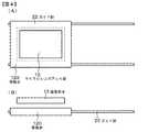
実施例1の撮像装置1において、マイクロレンズアレイ部12は、撮像装置1の光軸LLと所定の角度を成して(実施例1にあっては、具体的には、90度の角度を成して)、移動可能である。より具体的には、図3の(A)〜(C)及び図4の(A)〜(B)に模式図を示すように、移動手段は、マイクロレンズアレイ部12の移動のためのガイド部(ガイドシャフト)22と、図示しないリニアモータから構成されている。ガイド部(ガイドシャフト)22は、適切な方法で、撮像装置1の内部に取り付けられている。マイクロレンズアレイ部12が取り付けられた移動台120は、ガイド部(ガイドシャフト)22上を移動できる構造となっている。尚、マイクロレンズアレイ部12が第1の位置に位置している状態を正面及び頂面から眺めた模式図を、図3の(A)及び(B)のそれぞれに示し、図3の(A)〜(C)のそれぞれに示し、マイクロレンズアレイ部12が第2の位置に位置している状態を正面及び頂面から眺めた模式図を、図4の(A)及び(B)のそれぞれに示す。また、マイクロレンズアレイ部12等の模式的な断面図を図3の(C)に示す。 In the imaging device 1 of the first embodiment, the
実施例1の撮像装置1にあっては、撮像素子13からの信号に対して所定の画像処理を施すための画像処理部14を更に備えており、画像処理部14を制御する制御部16を更に備えている。そして、第1の撮像モードによる撮像時、画像処理部14による画像処理が停止され、第2の撮像モードによる撮像時、画像処理部14による画像処理が行われる。 The imaging apparatus 1 according to the first embodiment further includes an
実施例1、あるいは、後述する実施例2において、撮像レンズ11は、撮像対象物を撮像するためのメインレンズであり、例えば、ビデオカメラやスチルカメラ等で使用される一般的な撮像レンズから構成されている。また、マイクロレンズアレイ部12は、複数のマイクロレンズ12’が2次元マトリクス状に配列されて成り、撮像レンズ11の合焦点状態にも依るが、撮像レンズ11の焦点面に配置されている。尚、図中の符号f1は、撮像レンズ11の中心からマイクロレンズアレイ部12の結像面までの距離を表す。撮像素子13は、例えば、2次元マトリクス状に配列された複数のCCDから構成されている。撮像素子13においては、マイクロレンズアレイ部12から出射された光を受光して、撮像信号が生成される。撮像素子13は、マイクロレンズアレイ部12の焦点面に配置されている。尚、図中の符号f2は、マイクロレンズアレイ部12の中心から撮像素子13の撮像面までの距離(マイクロレンズ12’の焦点距離)を表す。撮像素子駆動手段15によって、撮像素子13が駆動され、撮像素子13の受光動作の制御が行われる。制御部16は、画像処理部14、撮像素子駆動手段15、及び、移動手段21の動作を制御する。具体的には、撮像素子駆動手段15の駆動動作を適宜制御すると共に、第1の撮像モード及び第2の撮像モードの2つの撮像モードに応じて、画像処理部14及び移動手段21の動作を制御する。制御部16は、マイクロコンピュータから構成されている。In Example 1 or Example 2 to be described later, the
実施例1、あるいは、後述する実施例2において、第2の撮像モードにあっては、画像処理部14において画像処理が施される。画像処理部14は、第2の撮像モードにおいて、撮像素子13で得られた信号(撮像信号)に対して所定の画像処理を施し、撮像データDoutとして出力する。具体的には、ライト・フィールド・フォトグラフィー技術に基づくリフォーカス(Refocusing)演算処理が行われる。そして、これによって、任意の視点や方向からの観察画像を再構築することができるし、画像の3次元情報を取得することができる。リフォーカス演算処理については後述する。In Example 1 or Example 2 described later, in the second imaging mode, the
実施例1、あるいは、後述する実施例2におけるマイクロレンズアレイ部12の模式的な一部断面図を図5に示す。また、マイクロレンズアレイ部12を構成するマイクロレンズ12’において、撮像レンズ11側の表面の曲率(r1)よりも、撮像素子13側の表面の曲率(r2)の方が大きい。具体的には、実施例1にあっては、r1/r2=0である。そして、マイクロレンズアレイ部12を構成するマイクロレンズ12’は、撮像素子13側に凸の凸レンズである。FIG. 5 shows a schematic partial cross-sectional view of the
図9の(A)及び(B)に、マイクロレンズアレイ部12及び撮像素子13の配置関係を模式的に示す。図9の(A)に示す例では、実施例1の撮像装置のように、マイクロレンズアレイ部12を構成するマイクロレンズ12’は、撮像素子13側に凸の凸レンズである。一方、図9の(B)に示す例では、マイクロレンズアレイ部12を構成するマイクロレンズ12’は、撮像レンズ11側に凸の凸レンズである。図9の(A)に示すマイクロレンズ12’、及び、図9の(B)に示すマイクロレンズ12’が、同じ焦点距離を有していたとしても、マイクロレンズアレイ部12の基部12”の厚さ分だけ、図9の(B)に示すマイクロレンズ12’の方が、マイクロレンズアレイ部12と撮像素子13との間の距離が短くなってしまう。従って、図9の(A)に示すマイクロレンズ12’の方が、図9の(B)に示すマイクロレンズ12’よりも、設計の自由度が高い。それ故、図9の(A)に示すマイクロレンズ12’の構成、構造を採用することが好ましい。 9A and 9B schematically show the arrangement relationship between the
実施例1の撮像装置1のように、様々な波長領域の光を含んだ自然光を撮像に利用する場合には、マイクロレンズ12’の撮像素子13側の表面を非球面とし、マイクロレンズ12’を非球面レンズとすることが好ましい。球面レンズで構成した場合と比べて、曲率を大きくすることができる結果、光学設計が容易になる。また、マイクロレンズ12’を回折レンズで構成した場合と比較すると、入射光を屈折させる際の波長依存性が無くなるため、軸上色収差等の発生を回避することができ、様々な波長領域の光を含んだ自然光による撮像に適した構成とすることができる。尚、単色光を用いたイメージング用途等の場合には、波長依存性や軸上色収差の問題が無いため、マイクロレンズ12’を回折レンズで構成した方が、非球面レンズで構成した場合と比べて、優れた光学特性を得ることができる場合がある。 When natural light including light in various wavelength regions is used for imaging as in the imaging device 1 of the first embodiment, the surface of the
図1、図2、図5、図6の(A)及び(B)を参照して、実施例1の撮像装置1の動作について詳細に説明する。ここで、図5は、マイクロレンズアレイ部12のレンズ効果を説明するための模式的な一部断面図である。 With reference to FIGS. 1, 2, 5, and 6 (A) and (B), the operation of the imaging apparatus 1 according to the first embodiment will be described in detail. Here, FIG. 5 is a schematic partial cross-sectional view for explaining the lens effect of the
実施例1の撮像装置1にあっては、第2の撮像モード時、制御部16の制御下、移動手段21が動作させられ、マイクロレンズアレイ部12を第2の位置に位置させる(図1参照)。そして、図1に示すように、撮像レンズ11を通過した光を、撮像レンズ11によって像が結像される位置に配置されたマイクロレンズアレイ部12を構成するマイクロレンズ12’を通過させ、撮像素子13の撮像面上に結像させる。こうして、撮像素子駆動手段15の制御下、撮像素子13から撮像信号が得られる。即ち、第2の撮像モードにあっては、図5に示すように、マイクロレンズ12’に入射した入射光L11は、マイクロレンズ12’において屈折され、光軸L0上の焦点である画素PL11に集光される。このように、第2の撮像モードによる撮像時、マイクロレンズ12’上に結像された撮像レンズ11による像を、撮像素子13上に再結像(集光、収束)させることができる。In the imaging apparatus 1 according to the first embodiment, in the second imaging mode, the moving
一方、第1の撮像モード時、制御部16の制御下、移動手段21が動作させられ、マイクロレンズアレイ部12を第1の位置に位置させる(図2参照)。そして、撮像レンズ11を通過した光を、マイクロレンズアレイ部12を通過させること無く、直接、撮像素子13の撮像面上に結像させる。即ち、撮像レンズ11による撮像対象物の像は、マイクロレンズアレイ部12によって何らの影響を受けること無く、撮像素子13上に結像する。こうして、撮像素子駆動手段15の制御下、撮像素子13から撮像信号が得られる。 On the other hand, in the first imaging mode, the moving
図5に示すように、マイクロレンズアレイ部12への入射光L11(実線で示す)は、撮像素子13上の点(画素)PL11に結像し、マイクロレンズアレイ部12への入射光L12(点線で示す)は、撮像素子13上の点(画素)PL12に結像し、マイクロレンズアレイ部12への入射光L13(一点鎖線で示す)は、撮像素子13上の点(画素)PL13に結像する。即ち、マイクロレンズアレイ部12への入射光の入射方向が異なると、撮像素子13上の異なる点(異なる画素)上に結像(集光)される。As shown in FIG. 5, incident light L11 (shown by a solid line) on the
このような結像状態は、撮像レンズ11における合焦点動作の最適化によって容易に行うことができ、例えば、オート・フォーカス処理において、第1の撮像モードによる撮像時と第2の撮像モードによる撮像時における合焦点動作(処理)の最適化を図ればよい。後述する実施例2においても同様である。 Such an imaging state can be easily performed by optimizing the in-focus operation in the
撮像素子13で得られた撮像信号は、画像処理部14へ送出される。そして、画像処理部14では、制御部16の制御下、この撮像信号に対して所定の画像処理が施され、撮像データDoutとして出力される。具体的には、第1の撮像モードにあっては、制御部16の制御下、画像処理部14による画像処理を停止させる結果、入力した撮像信号がそのまま撮像データDoutとして出力される。一方、第2の撮像モードにあっては、制御部16の制御下、画像処理部14による画像処理(リフォーカス演算処理)がなされる結果、入力した撮像信号に対して所定の画像処理が施され、撮像データDoutとして出力される。An imaging signal obtained by the
ここで、図6の(A)及び(B)を参照して、画像処理部14における画像処理のリフォーカス演算処理について詳細に説明する。このリフォーカス演算処理は、後述する実施例2に対しても同様に適用される。 Here, with reference to FIGS. 6A and 6B, the refocus calculation processing of the image processing in the
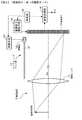
図6の(A)に示すように、撮像レンズ11の撮像レンズ面11A上において直交座標系(u,v)を想定し、撮像素子13の撮像面13A上において直交座標系(x,y)を想定する。撮像レンズ11の撮像レンズ面と撮像素子13の撮像面との間の距離をfとすると、図6の(A)に示すような撮像レンズ11及び撮像素子13を通る光線L14は、4次元関数LF(x,y,u,v)で表すことができる。従って、光線L14の位置情報に加え、光線L14の進行方向の情報を得ることができる。そして、この場合、図6の(B)に示すように撮像レンズ面11A、撮像面13A及びリフォーカス面(撮像レンズ11による像が結像されるマイクロレンズアレイ部12の結像面)12A間の位置関係を設定した場合、即ち、f’=α・fとなるようにリフォーカス面12Aを設定した場合、リフォーカス面12A上の座標(s,t)の撮像面13A上における検出光強度LF'(s,t,u,v)は、以下の式(1)で表すことができる。また、リフォーカス面12Aで得られるイメージEF'(s,t)は、検出光強度LF'(s,t,u,v)をレンズ口径に関して積分したものであるので、以下の式(2)で表すことができる。従って、式(2)に基づきリフォーカス演算を行うことによって、ライト・フィールド・フォトグラフィー技術に基づく撮像データDoutにより、任意の視点や方向からの観察画像を再構築することができるし、画像の3次元情報を取得することができる。As shown in FIG. 6A, an orthogonal coordinate system (u, v) is assumed on the

このように、実施例1にあっては、第1の撮像モードによる撮像時、撮像レンズ11を通過した光は、マイクロレンズアレイ部12を通過すること無く、直接、撮像素子13の撮像面13A上に結像し、第2の撮像モードによる撮像時、撮像レンズ11を通過した光は、撮像レンズ11によって像が結像される位置に配置されたマイクロレンズアレイ部12を構成するマイクロレンズ12’を通過し、撮像素子13の撮像面13A上に結像する。従って、移動手段21といった簡素な構成、構造により、第1の撮像モードと第2の撮像モードとの間での撮像モードの切り替えを容易に行うことができる。 As described above, in the first embodiment, at the time of imaging in the first imaging mode, the light that has passed through the
更には、マイクロレンズ12’を非球面レンズから構成すれば、球面レンズから構成した場合と比較して、曲率を大きくすることができるので、光学設計を容易にすることが可能となる。また、回折レンズで構成した場合と比較すると、入射光を屈折させる際の波長依存性を無くすことができ、軸上色収差等の発生を回避することができる。それ故、様々な波長領域の光を含んだ自然光を利用する撮像装置として最適な構成とすることが可能となる。 Furthermore, if the
実施例2は、実施例1の変形に関し、具体的には、第1Bの構成に関する。実施例2の撮像装置の概念図を、図7(第2の撮像モード時)及び図8(第1の撮像モード時)に示すが、実施例2の撮像装置2にあっては、撮像装置2の光軸LLに直交する仮想の軸(図7及び図8においては、軸「A」で示す)と平行な回動軸32を中心として、マイクロレンズアレイ部12は回動可能である。ここで、移動手段31は、この回動軸32に接続されたギヤとモータとの組合せ(これらは図示せず)から構成されている。また、マイクロレンズアレイ部12は、実施例1と同様に、移動台(図示せず)に取り付けられており、移動台の端部に回動軸32が配置されている。回動軸32は、適切な方法で、撮像装置2の内部に取り付けられている。 The second embodiment relates to a modification of the first embodiment, and specifically relates to the configuration of 1B. FIG. 7 (in the second imaging mode) and FIG. 8 (in the first imaging mode) are conceptual diagrams of the imaging apparatus of the second embodiment. In the imaging apparatus 2 of the second embodiment, the imaging apparatus The
実施例2の撮像装置2にあっても、第1の撮像モードによる撮像時(通常の高解像度の撮像モードによる撮像時)、移動手段31の動作に基づき、マイクロレンズアレイ部12は第1の位置に位置し(図8参照)、撮像レンズ11を通過した光は、マイクロレンズアレイ部12を通過すること無く、直接、撮像素子(撮像手段)13の撮像面上に結像する。一方、第2の撮像モードによる撮像時(ライト・フィールド・フォトグラフィー技術に基づく撮像モードによる撮像時)、移動手段31の動作に基づき、マイクロレンズアレイ部12は第2の位置に位置(図7参照)し、撮像レンズ11を通過した光は、撮像レンズ11によって像が結像される位置に配置されたマイクロレンズアレイ部12を構成するマイクロレンズ12’を通過し、撮像素子13の撮像面13A上に結像する。 Even in the imaging apparatus 2 according to the second embodiment, the
移動手段31の構成、構造が相違している点を除き、実施例2の撮像装置2の構成、構造は、実施例1の撮像装置1の構成、構造と同じとすることができるので、詳細な説明は省略する。 Except for the difference in the configuration and structure of the moving means 31, the configuration and structure of the imaging device 2 of the second embodiment can be the same as the configuration and structure of the imaging device 1 of the first embodiment. The detailed explanation is omitted.
以上、本発明を好ましい実施例に基づき説明したが、本発明はこれらの実施例に限定するものではなく、種々の変形が可能である。実施例にあっては、画像処理部14における画像処理方法として、ライト・フィールド・フォトグラフィー技術に基づくリフォーカス演算処理について説明したが、画像処理部14における画像処理方法は、これに限られず、他の画像処理方法(例えば、視野を振るといった画像処理や、マイクロレンズアレイ部及び撮像素子を一種のステレオ・カメラとして機能させることで得られる距離算出といった画像処理)としてもよい。 As mentioned above, although this invention was demonstrated based on the preferable Example, this invention is not limited to these Examples, A various deformation | transformation is possible. In the embodiment, the refocus calculation process based on the light field photography technique has been described as the image processing method in the
1,2・・・撮像装置、11・・・撮像レンズ、11A・・・撮像レンズ面、11’・・・入射瞳径、12・・・マイクロレンズアレイ部、12’・・・マイクロレンズ、12A・・・リフォーカス面、13・・・撮像素子、13A・・・撮像面、14・・・画像処理部、15・・・撮像素子駆動手段、16・・・制御部、21,31・・・移動手段、22・・・ガイド部(ガイドシャフト)、32・・・回動軸、120・・・移動台DESCRIPTION OF SYMBOLS 1, 2 ... Imaging device, 11 ... Imaging lens, 11A ... Imaging lens surface, 11 '... Incidence pupil diameter, 12 ... Micro lens array part, 12' ... Micro lens, 12A ... refocusing surface, 13 ... imaging device, 13A ... imaging surface, 14 ... image processing unit, 15 ... imaging device driving means, 16 ... control unit, 21, 31, ..Moving means, 22 ... guide part (guide shaft), 32 ... rotating shaft, 120 ... moving table
Claims (7)
Translated fromJapanese(B)マイクロレンズアレイ部、
(C)撮像素子、及び、
(D)マイクロレンズアレイ部を移動させるための移動手段、
を備えており、
第1の撮像モード及び第2の撮像モードによって撮像がなされ、
マイクロレンズアレイ部は、移動手段の動作に基づき、第1の位置と第2の位置との間を移動可能であり、
第1の撮像モードによる撮像時、マイクロレンズアレイ部は第1の位置に位置し、撮像レンズを通過した光は、マイクロレンズアレイ部を通過すること無く、直接、撮像素子の撮像面上に結像し、
第2の撮像モードによる撮像時、マイクロレンズアレイ部は第2の位置に位置し、撮像レンズを通過した光は、撮像レンズによって像が結像される位置に配置されたマイクロレンズアレイ部を構成するマイクロレンズを通過し、撮像素子の撮像面上に結像することを特徴とする撮像装置。(A) an imaging lens,
(B) Micro lens array part,
(C) an image sensor, and
(D) moving means for moving the microlens array section;
With
Imaging is performed in the first imaging mode and the second imaging mode,
The microlens array part is movable between the first position and the second position based on the operation of the moving means,
During imaging in the first imaging mode, the microlens array unit is located at the first position, and light that has passed through the imaging lens is directly coupled onto the imaging surface of the imaging element without passing through the microlens array unit. Image
During imaging in the second imaging mode, the microlens array unit is located at the second position, and the light that has passed through the imaging lens constitutes a microlens array unit that is disposed at a position where an image is formed by the imaging lens. An image pickup apparatus that passes through a microlens and forms an image on an image pickup surface of an image pickup device.
第1の撮像モードによる撮像時、画像処理部による画像処理が停止され、
第2の撮像モードによる撮像時、画像処理部による画像処理が行われることを特徴とする請求項1に記載の撮像装置。An image processing unit for performing predetermined image processing on a signal from the image sensor;
During imaging in the first imaging mode, image processing by the image processing unit is stopped,
The imaging apparatus according to claim 1, wherein image processing by the image processing unit is performed during imaging in the second imaging mode.
(B)マイクロレンズアレイ部、
(C)撮像素子、及び、
(D)マイクロレンズアレイ部を移動させるための移動手段、
を備えており、
マイクロレンズアレイ部は、移動手段の動作に基づき、第1の位置と第2の位置との間を移動可能である撮像装置を用いた撮像方法であって、
第1の撮像モードによる撮像時、マイクロレンズアレイ部を第1の位置に位置させ、撮像レンズを通過した光を、マイクロレンズアレイ部を通過させること無く、直接、撮像素子の撮像面上に結像させ、
第2の撮像モードによる撮像時、マイクロレンズアレイ部を第2の位置に位置させ、撮像レンズを通過した光を、撮像レンズによって像が結像される位置に配置されたマイクロレンズアレイ部を構成するマイクロレンズを通過させ、撮像素子の撮像面上に結像させることを特徴とする撮像方法。(A) an imaging lens,
(B) Micro lens array part,
(C) an image sensor, and
(D) moving means for moving the microlens array section;
With
The microlens array unit is an imaging method using an imaging device that can move between a first position and a second position based on an operation of a moving unit,
During imaging in the first imaging mode, the microlens array unit is positioned at the first position, and the light that has passed through the imaging lens is directly coupled onto the imaging surface of the imaging element without passing through the microlens array unit. Image
At the time of imaging in the second imaging mode, the microlens array unit is positioned at the second position, and the microlens array unit is configured such that light passing through the imaging lens is arranged at a position where an image is formed by the imaging lens An imaging method comprising: passing through a microlens to form an image on an imaging surface of an imaging device.
Priority Applications (4)
| Application Number | Priority Date | Filing Date | Title |
|---|---|---|---|
| JP2007159738AJP2008312080A (en) | 2007-06-18 | 2007-06-18 | Imaging apparatus and imaging method |
| US12/149,555US9113066B2 (en) | 2007-06-18 | 2008-05-05 | Imaging device and method with transporting microlens array |
| TW97117479ATWI380051B (en) | 2007-06-18 | 2008-05-12 | Imaging device and method |
| CN2008101253045ACN101330574B (en) | 2007-06-18 | 2008-06-18 | Imaging device and method |
Applications Claiming Priority (1)
| Application Number | Priority Date | Filing Date | Title |
|---|---|---|---|
| JP2007159738AJP2008312080A (en) | 2007-06-18 | 2007-06-18 | Imaging apparatus and imaging method |
Publications (1)
| Publication Number | Publication Date |
|---|---|
| JP2008312080Atrue JP2008312080A (en) | 2008-12-25 |
Family
ID=40131931
Family Applications (1)
| Application Number | Title | Priority Date | Filing Date |
|---|---|---|---|
| JP2007159738APendingJP2008312080A (en) | 2007-06-18 | 2007-06-18 | Imaging apparatus and imaging method |
Country Status (4)
| Country | Link |
|---|---|
| US (1) | US9113066B2 (en) |
| JP (1) | JP2008312080A (en) |
| CN (1) | CN101330574B (en) |
| TW (1) | TWI380051B (en) |
Cited By (16)
| Publication number | Priority date | Publication date | Assignee | Title |
|---|---|---|---|---|
| JP2009017079A (en)* | 2007-07-03 | 2009-01-22 | Sony Corp | Imaging apparatus and imaging method |
| JP2012060460A (en)* | 2010-09-09 | 2012-03-22 | Olympus Corp | Photographing apparatus |
| CN102739945A (en)* | 2012-05-24 | 2012-10-17 | 上海理工大学 | Optical field imaging device and method |
| WO2013054469A1 (en)* | 2011-10-13 | 2013-04-18 | パナソニック株式会社 | Depth estimate image capture device and image capture element |
| JP2013517510A (en)* | 2010-01-19 | 2013-05-16 | ヴィジョンゲイト,インコーポレーテッド | Tomography light irradiation field microscope |
| JP2013198016A (en)* | 2012-03-21 | 2013-09-30 | Casio Comput Co Ltd | Imaging apparatus |
| JP2013243522A (en)* | 2012-05-21 | 2013-12-05 | Canon Inc | Image pickup device |
| JP2014155008A (en)* | 2013-02-07 | 2014-08-25 | Canon Inc | Image pickup device, control method therefor, and program |
| JP2014158070A (en)* | 2013-02-14 | 2014-08-28 | Canon Inc | Image processing apparatus, image pickup apparatus, image processing method, image processing program, and storage medium |
| JP2015008484A (en)* | 2014-08-01 | 2015-01-15 | キヤノン株式会社 | Imaging apparatus |
| JP2015082721A (en)* | 2013-10-22 | 2015-04-27 | キヤノン株式会社 | Imaging apparatus, control method thereof, and program |
| CN104614847A (en)* | 2015-01-14 | 2015-05-13 | 浙江大学 | Wide view field high definition microimaging system and method |
| CN104735351A (en)* | 2015-03-06 | 2015-06-24 | 中国科学院计算技术研究所 | High resolution light field image recreation method and imaging device |
| KR101613682B1 (en)* | 2009-10-20 | 2016-04-19 | 삼성전자주식회사 | Apparatus and method for processing image using light field data |
| US10819899B2 (en) | 2017-05-16 | 2020-10-27 | Olympus Corporation | Image acquisition device and image acquisition system |
| US10852457B2 (en) | 2017-05-16 | 2020-12-01 | Olympus Corporation | Imaging device |
Families Citing this family (60)
| Publication number | Priority date | Publication date | Assignee | Title |
|---|---|---|---|---|
| US10298834B2 (en) | 2006-12-01 | 2019-05-21 | Google Llc | Video refocusing |
| US8559705B2 (en) | 2006-12-01 | 2013-10-15 | Lytro, Inc. | Interactive refocusing of electronic images |
| US8279325B2 (en) | 2008-11-25 | 2012-10-02 | Lytro, Inc. | System and method for acquiring, editing, generating and outputting video data |
| US8289440B2 (en)* | 2008-12-08 | 2012-10-16 | Lytro, Inc. | Light field data acquisition devices, and methods of using and manufacturing same |
| US8908058B2 (en)* | 2009-04-18 | 2014-12-09 | Lytro, Inc. | Storage and transmission of pictures including multiple frames |
| US8749620B1 (en) | 2010-02-20 | 2014-06-10 | Lytro, Inc. | 3D light field cameras, images and files, and methods of using, operating, processing and viewing same |
| US9167138B2 (en)* | 2010-12-06 | 2015-10-20 | Apple Inc. | Pattern projection and imaging using lens arrays |
| US8768102B1 (en) | 2011-02-09 | 2014-07-01 | Lytro, Inc. | Downsampling light field images |
| JP5214754B2 (en)* | 2011-02-25 | 2013-06-19 | 株式会社東芝 | Solid-state imaging device and portable information terminal |
| JP5331838B2 (en)* | 2011-02-25 | 2013-10-30 | 株式会社東芝 | Solid-state imaging device and portable information terminal |
| US9184199B2 (en) | 2011-08-01 | 2015-11-10 | Lytro, Inc. | Optical assembly including plenoptic microlens array |
| JP5623356B2 (en)* | 2011-08-29 | 2014-11-12 | キヤノン株式会社 | Imaging device |
| US20130076966A1 (en)* | 2011-09-22 | 2013-03-28 | John Norvold Border | Digital imaging system with refocusable imaging mode |
| WO2013043488A1 (en)* | 2011-09-22 | 2013-03-28 | Eastman Kodak Company | Digital imaging system with refocusable imaging mode |
| US8593564B2 (en)* | 2011-09-22 | 2013-11-26 | Apple Inc. | Digital camera including refocusable imaging mode adaptor |
| US8811769B1 (en) | 2012-02-28 | 2014-08-19 | Lytro, Inc. | Extended depth of field and variable center of perspective in light-field processing |
| US8995785B2 (en) | 2012-02-28 | 2015-03-31 | Lytro, Inc. | Light-field processing and analysis, camera control, and user interfaces and interaction on light-field capture devices |
| US8831377B2 (en) | 2012-02-28 | 2014-09-09 | Lytro, Inc. | Compensating for variation in microlens position during light-field image processing |
| US8948545B2 (en) | 2012-02-28 | 2015-02-03 | Lytro, Inc. | Compensating for sensor saturation and microlens modulation during light-field image processing |
| US9420276B2 (en) | 2012-02-28 | 2016-08-16 | Lytro, Inc. | Calibration of light-field camera geometry via robust fitting |
| CN102621602A (en)* | 2012-04-13 | 2012-08-01 | 中国科学院光电技术研究所 | A kind of preparation method of double-plane super-resolution imaging lens |
| JP5851320B2 (en)* | 2012-04-18 | 2016-02-03 | 株式会社東芝 | The camera module |
| CN104303493A (en) | 2012-05-09 | 2015-01-21 | 莱特洛公司 | Optimization of Optical Systems for Improved Light Field Capture and Manipulation |
| US9179126B2 (en)* | 2012-06-01 | 2015-11-03 | Ostendo Technologies, Inc. | Spatio-temporal light field cameras |
| US9607424B2 (en) | 2012-06-26 | 2017-03-28 | Lytro, Inc. | Depth-assigned content for depth-enhanced pictures |
| US9858649B2 (en) | 2015-09-30 | 2018-01-02 | Lytro, Inc. | Depth-based image blurring |
| US10129524B2 (en) | 2012-06-26 | 2018-11-13 | Google Llc | Depth-assigned content for depth-enhanced virtual reality images |
| US8997021B2 (en) | 2012-11-06 | 2015-03-31 | Lytro, Inc. | Parallax and/or three-dimensional effects for thumbnail image displays |
| US9001226B1 (en)* | 2012-12-04 | 2015-04-07 | Lytro, Inc. | Capturing and relighting images using multiple devices |
| US10334151B2 (en) | 2013-04-22 | 2019-06-25 | Google Llc | Phase detection autofocus using subaperture images |
| CN104580877B (en) | 2013-10-29 | 2018-03-06 | 华为技术有限公司 | The device and method that image obtains |
| US9706116B2 (en)* | 2013-10-31 | 2017-07-11 | Ricoh Co., Ltd. | Plenoptic color imaging system with enhanced resolution |
| US9525819B2 (en)* | 2014-03-07 | 2016-12-20 | Ricoh Company, Ltd. | Enhancing spatial resolution of images from light field imaging systems using sub-pixel disparity |
| GB2544946B (en) | 2014-08-31 | 2021-03-10 | Berestka John | Systems and methods for analyzing the eye |
| US9635332B2 (en) | 2014-09-08 | 2017-04-25 | Lytro, Inc. | Saturated pixel recovery in light-field images |
| CN105635530B (en)* | 2014-11-03 | 2019-04-30 | 北京蚁视科技有限公司 | Optical field imaging system |
| CN104469110B (en)* | 2014-11-26 | 2017-07-21 | 西北工业大学 | The optical field acquisition device of variable-angle hits |
| CN105812623B (en)* | 2014-12-30 | 2018-10-16 | 深圳超多维科技有限公司 | Microlens array imaging device and imaging method |
| US10567464B2 (en) | 2015-04-15 | 2020-02-18 | Google Llc | Video compression with adaptive view-dependent lighting removal |
| US10440407B2 (en) | 2017-05-09 | 2019-10-08 | Google Llc | Adaptive control for immersive experience delivery |
| US10341632B2 (en) | 2015-04-15 | 2019-07-02 | Google Llc. | Spatial random access enabled video system with a three-dimensional viewing volume |
| US10412373B2 (en) | 2015-04-15 | 2019-09-10 | Google Llc | Image capture for virtual reality displays |
| US10275898B1 (en) | 2015-04-15 | 2019-04-30 | Google Llc | Wedge-based light-field video capture |
| US10565734B2 (en) | 2015-04-15 | 2020-02-18 | Google Llc | Video capture, processing, calibration, computational fiber artifact removal, and light-field pipeline |
| US10444931B2 (en) | 2017-05-09 | 2019-10-15 | Google Llc | Vantage generation and interactive playback |
| US11328446B2 (en) | 2015-04-15 | 2022-05-10 | Google Llc | Combining light-field data with active depth data for depth map generation |
| US10540818B2 (en) | 2015-04-15 | 2020-01-21 | Google Llc | Stereo image generation and interactive playback |
| US10546424B2 (en) | 2015-04-15 | 2020-01-28 | Google Llc | Layered content delivery for virtual and augmented reality experiences |
| US10469873B2 (en) | 2015-04-15 | 2019-11-05 | Google Llc | Encoding and decoding virtual reality video |
| US10419737B2 (en) | 2015-04-15 | 2019-09-17 | Google Llc | Data structures and delivery methods for expediting virtual reality playback |
| US9979909B2 (en) | 2015-07-24 | 2018-05-22 | Lytro, Inc. | Automatic lens flare detection and correction for light-field images |
| US10275892B2 (en) | 2016-06-09 | 2019-04-30 | Google Llc | Multi-view scene segmentation and propagation |
| US10679361B2 (en) | 2016-12-05 | 2020-06-09 | Google Llc | Multi-view rotoscope contour propagation |
| US10594945B2 (en) | 2017-04-03 | 2020-03-17 | Google Llc | Generating dolly zoom effect using light field image data |
| US10474227B2 (en) | 2017-05-09 | 2019-11-12 | Google Llc | Generation of virtual reality with 6 degrees of freedom from limited viewer data |
| US10354399B2 (en) | 2017-05-25 | 2019-07-16 | Google Llc | Multi-view back-projection to a light-field |
| US10545215B2 (en) | 2017-09-13 | 2020-01-28 | Google Llc | 4D camera tracking and optical stabilization |
| US10965862B2 (en) | 2018-01-18 | 2021-03-30 | Google Llc | Multi-camera navigation interface |
| US11343435B2 (en)* | 2019-12-26 | 2022-05-24 | Waymo Llc | Microlensing for real-time sensing of stray light |
| CN115250320B (en)* | 2021-04-28 | 2024-06-14 | 北京小米移动软件有限公司 | Image acquisition method and device, electronic device, and storage medium |
Family Cites Families (11)
| Publication number | Priority date | Publication date | Assignee | Title |
|---|---|---|---|---|
| US4887107A (en)* | 1986-07-29 | 1989-12-12 | Minolta Camera Kabushiki Kaisha | Camera |
| US6563567B1 (en)* | 1998-12-17 | 2003-05-13 | Nikon Corporation | Method and apparatus for illuminating a surface using a projection imaging apparatus |
| JP3605101B2 (en) | 2001-08-01 | 2004-12-22 | キヤノン株式会社 | Drive control device, video display device, drive control method, and design assets |
| JP3900282B2 (en)* | 2002-03-14 | 2007-04-04 | ソニー株式会社 | Imaging device and zoom lens |
| JP2003330419A (en) | 2002-05-15 | 2003-11-19 | Semiconductor Energy Lab Co Ltd | Display device |
| JP2004191893A (en)* | 2002-12-13 | 2004-07-08 | Canon Inc | Imaging apparatus |
| JP4235539B2 (en)* | 2003-12-01 | 2009-03-11 | 独立行政法人科学技術振興機構 | Image composition apparatus and image composition method |
| JP2006030318A (en) | 2004-07-12 | 2006-02-02 | Sanyo Electric Co Ltd | Display device |
| EP2398224B1 (en) | 2004-10-01 | 2016-01-13 | The Board of Trustees of The Leland Stanford Junior University | Imaging arrangements and methods therefor |
| JP5040493B2 (en) | 2006-12-04 | 2012-10-03 | ソニー株式会社 | Imaging apparatus and imaging method |
| JP2008294741A (en) | 2007-05-24 | 2008-12-04 | Olympus Corp | Imaging system |
- 2007
- 2007-06-18JPJP2007159738Apatent/JP2008312080A/enactivePending
- 2008
- 2008-05-05USUS12/149,555patent/US9113066B2/enactiveActive
- 2008-05-12TWTW97117479Apatent/TWI380051B/ennot_activeIP Right Cessation
- 2008-06-18CNCN2008101253045Apatent/CN101330574B/ennot_activeExpired - Fee Related
Cited By (20)
| Publication number | Priority date | Publication date | Assignee | Title |
|---|---|---|---|---|
| JP2009017079A (en)* | 2007-07-03 | 2009-01-22 | Sony Corp | Imaging apparatus and imaging method |
| KR101613682B1 (en)* | 2009-10-20 | 2016-04-19 | 삼성전자주식회사 | Apparatus and method for processing image using light field data |
| JP2013517510A (en)* | 2010-01-19 | 2013-05-16 | ヴィジョンゲイト,インコーポレーテッド | Tomography light irradiation field microscope |
| JP2012060460A (en)* | 2010-09-09 | 2012-03-22 | Olympus Corp | Photographing apparatus |
| JPWO2013054469A1 (en)* | 2011-10-13 | 2015-03-30 | パナソニックIpマネジメント株式会社 | Depth estimation imaging device and imaging device |
| US9456198B2 (en) | 2011-10-13 | 2016-09-27 | Panasonic Intellectual Property Management Co., Ltd. | Depth estimating image capture device and image sensor |
| WO2013054469A1 (en)* | 2011-10-13 | 2013-04-18 | パナソニック株式会社 | Depth estimate image capture device and image capture element |
| JP2013198016A (en)* | 2012-03-21 | 2013-09-30 | Casio Comput Co Ltd | Imaging apparatus |
| JP2013243522A (en)* | 2012-05-21 | 2013-12-05 | Canon Inc | Image pickup device |
| US9338336B2 (en) | 2012-05-21 | 2016-05-10 | Canon Kabushiki Kaisha | Image pickup apparatus |
| CN102739945A (en)* | 2012-05-24 | 2012-10-17 | 上海理工大学 | Optical field imaging device and method |
| JP2014155008A (en)* | 2013-02-07 | 2014-08-25 | Canon Inc | Image pickup device, control method therefor, and program |
| US9451175B2 (en) | 2013-02-07 | 2016-09-20 | Canon Kabushiki Kaisha | Imaging apparatus, information processing device, image pickup method, and non-transitory computer-readable storage medium storing a program therefor for obtaining light field information |
| JP2014158070A (en)* | 2013-02-14 | 2014-08-28 | Canon Inc | Image processing apparatus, image pickup apparatus, image processing method, image processing program, and storage medium |
| JP2015082721A (en)* | 2013-10-22 | 2015-04-27 | キヤノン株式会社 | Imaging apparatus, control method thereof, and program |
| JP2015008484A (en)* | 2014-08-01 | 2015-01-15 | キヤノン株式会社 | Imaging apparatus |
| CN104614847A (en)* | 2015-01-14 | 2015-05-13 | 浙江大学 | Wide view field high definition microimaging system and method |
| CN104735351A (en)* | 2015-03-06 | 2015-06-24 | 中国科学院计算技术研究所 | High resolution light field image recreation method and imaging device |
| US10819899B2 (en) | 2017-05-16 | 2020-10-27 | Olympus Corporation | Image acquisition device and image acquisition system |
| US10852457B2 (en) | 2017-05-16 | 2020-12-01 | Olympus Corporation | Imaging device |
Also Published As
| Publication number | Publication date |
|---|---|
| CN101330574B (en) | 2010-12-22 |
| CN101330574A (en) | 2008-12-24 |
| TW200907412A (en) | 2009-02-16 |
| US9113066B2 (en) | 2015-08-18 |
| US20080309813A1 (en) | 2008-12-18 |
| TWI380051B (en) | 2012-12-21 |
Similar Documents
| Publication | Publication Date | Title |
|---|---|---|
| JP2008312080A (en) | Imaging apparatus and imaging method | |
| JP4730347B2 (en) | Imaging apparatus and imaging method | |
| JP5040493B2 (en) | Imaging apparatus and imaging method | |
| EP2008445B1 (en) | Improved plenoptic camera | |
| JP6220125B2 (en) | Imaging apparatus and control method thereof | |
| EP2227896B1 (en) | Fast computational camera based on two arrays of lenses | |
| JP4264569B2 (en) | Imaging device | |
| US9823453B2 (en) | Catadioptric light-field lens and image pickup apparatus including the same | |
| KR102297488B1 (en) | Light field camera | |
| WO2007024709A3 (en) | Cellular phone camera with three-dimensional imaging function | |
| JP2014010400A5 (en) | ||
| WO2012043212A1 (en) | Imaging device | |
| JP2009500680A (en) | 3D image recognizer | |
| US10620137B2 (en) | Contact lens inspection system | |
| KR101950726B1 (en) | A Multiscale imaging system | |
| US10491791B2 (en) | Imaging apparatus and image sensor | |
| US20150237326A1 (en) | Sole channel 3d image capture apparatus | |
| KR101957353B1 (en) | Multiscale Imaging system with mirror rotation | |
| KR101819977B1 (en) | Dual Lens Multiscale Imaging System | |
| JP2015161904A (en) | Optical element, imaging element, and imaging apparatus | |
| KR101756328B1 (en) | Bidirectional Multiscale Imaging System |
Legal Events
| Date | Code | Title | Description |
|---|---|---|---|
| A621 | Written request for application examination | Free format text:JAPANESE INTERMEDIATE CODE: A621 Effective date:20081007 | |
| A977 | Report on retrieval | Free format text:JAPANESE INTERMEDIATE CODE: A971007 Effective date:20090409 | |
| A131 | Notification of reasons for refusal | Free format text:JAPANESE INTERMEDIATE CODE: A131 Effective date:20090421 | |
| A521 | Request for written amendment filed | Free format text:JAPANESE INTERMEDIATE CODE: A523 Effective date:20090610 | |
| A02 | Decision of refusal | Free format text:JAPANESE INTERMEDIATE CODE: A02 Effective date:20090714 |