JP2008312002A - Television conference apparatus - Google Patents
Television conference apparatusDownload PDFInfo
- Publication number
- JP2008312002A JP2008312002AJP2007158776AJP2007158776AJP2008312002AJP 2008312002 AJP2008312002 AJP 2008312002AJP 2007158776 AJP2007158776 AJP 2007158776AJP 2007158776 AJP2007158776 AJP 2007158776AJP 2008312002 AJP2008312002 AJP 2008312002A
- Authority
- JP
- Japan
- Prior art keywords
- sound
- level
- signal
- input
- sound collection
- Prior art date
- Legal status (The legal status is an assumption and is not a legal conclusion. Google has not performed a legal analysis and makes no representation as to the accuracy of the status listed.)
- Pending
Links
- 230000003044adaptive effectEffects0.000claimsabstractdescription10
- 230000005236sound signalEffects0.000claimsdescription81
- 238000000034methodMethods0.000claimsdescription2
- 230000003321amplificationEffects0.000abstractdescription2
- 238000003199nucleic acid amplification methodMethods0.000abstractdescription2
- 230000003247decreasing effectEffects0.000abstract1
- 238000010586diagramMethods0.000description7
- 238000006243chemical reactionMethods0.000description4
- 230000002238attenuated effectEffects0.000description3
- 238000001514detection methodMethods0.000description3
- 244000309464bullSpecies0.000description1
- 230000007423decreaseEffects0.000description1
- 230000006870functionEffects0.000description1
- 238000011144upstream manufacturingMethods0.000description1
Images


Landscapes
- Circuit For Audible Band Transducer (AREA)
- Two-Way Televisions, Distribution Of Moving Picture Or The Like (AREA)
- Obtaining Desirable Characteristics In Audible-Bandwidth Transducers (AREA)
Abstract
Description
Translated fromJapaneseこの発明は、モニタ付近にスピーカ、マイク、およびカメラを近接して設置したテレビ会議装置に関する。 The present invention relates to a video conference apparatus in which a speaker, a microphone, and a camera are installed in the vicinity of a monitor.
近年、遠隔地において通信会議を行う通信会議装置が普及している。通信会議装置は、マイクで収音した音声を相手側に送信し、相手側から音声を受信する。また、最近では映像データを送受信するテレビ会議装置が普及している(例えば特許文献1参照)。特許文献1の装置では、会議室全体の撮影映像と、発言者をズームアップした撮影映像と、を切り換えて送信することができる。 In recent years, communication conference apparatuses that perform communication conferences at remote locations have become widespread. The communication conference device transmits the sound collected by the microphone to the other party and receives the voice from the other party. Recently, video conference devices that transmit and receive video data have become widespread (see, for example, Patent Document 1). With the apparatus of
テレビ会議では、各会議参加者は相手の映像が映し出されているモニタの方向を見ながら会話することが自然である。したがって、スピーカ、およびカメラをモニタ付近に設置することが一般的である。
しかし、特許文献1の装置では、話者の位置を特定するために、各話者の位置にマイクを設置していた。この場合、話者の人数分のマイクを設置しなければならず、コストがかかり、汎用性に乏しいものであった。
一方、指向性マイクをモニタ付近に設置することも考えられるが、会議参加者は、装置前面に設置された会議机を囲むようにして在席することが一般的であり、各話者の位置により距離が変化する(例えば装置正面方向は遠くなる)ため、話者毎の収音レベルが大きく変化する。However, in the apparatus of
On the other hand, a directional microphone may be installed near the monitor, but it is common for conference participants to sit around the conference desk installed on the front of the device, and the distance depends on the location of each speaker. (For example, the front direction of the apparatus becomes far) changes, so that the sound collection level for each speaker changes greatly.
この発明は、話者の位置による収音レベルの変化を抑えたテレビ会議装置であって、モニタ付近にスピーカ、マイク、およびカメラを近接して設置したテレビ会議装置を提供することを目的とする。 It is an object of the present invention to provide a video conference apparatus that suppresses a change in the sound pickup level due to the position of a speaker, and in which a speaker, a microphone, and a camera are installed in the vicinity of a monitor. .
この発明のテレビ会議装置は、映像を撮影するカメラ、音声を放音する放音部、および音声を収音する収音部を近接する位置に備えたテレビ会議装置であって、前記収音部は、複数のマイクを配列してなるマイクアレイと、複数の方向に対して収音ビームを形成するとともに、各収音ビーム強度を比較することで話者方位を同定し、話者方位に対応する収音ビームを選択し、この選択した収音ビームを収音信号として出力する収音制御部と、からなり、外部から入力された入力信号を信号処理し、前記放音部に入力する入力信号処理部と、前記収音信号のレベルを減衰、または増幅するレベル調整回路と、前記レベル調整回路の調整量を前記話者方位毎に記憶する設定テーブルと、前記収音制御部から同定した話者方位を入力し、前記設定テーブルを読み出して該話者方位に対応する調整量を前記レベル調整回路に設定する制御部と、を備えたことを特徴とする。 The video conference apparatus according to the present invention is a video conference apparatus including a camera that shoots video, a sound emitting unit that emits sound, and a sound collecting unit that collects sound at close positions, the sound collecting unit The speaker array is identified by comparing the collected sound beam intensities with a microphone array formed by arranging multiple microphones, and by comparing the collected beam intensities. A sound collection control unit that selects a sound collection beam to be output and outputs the selected sound collection beam as a sound collection signal, and performs input processing on an input signal input from the outside and inputs the signal to the sound emission unit Identified from a signal processing unit, a level adjustment circuit that attenuates or amplifies the level of the collected sound signal, a setting table that stores the adjustment amount of the level adjustment circuit for each speaker orientation, and the sound collection control unit Enter the speaker direction, and And a control unit that sets an adjustment amount corresponding to 該話's azimuth reads Bull to the level adjusting circuit, and further comprising a.
この構成では、複数の方向に収音ビームを形成し、これらの収音ビーム強度から話者方位を同定する。制御部は、同定した話者方位に対応するレベル調整量を設定テーブルから読み出し、レベル調整回路に設定する。例えば、テレビ会議装置の正面方向に対応する話者方位であれば、音声信号を増幅する調整量とし、テレビ会議装置の側面方向に対応する話者方位であれば、音声信号を減衰(またはそのまま出力)する調整量とする。これは、会議参加者がテレビ会議装置の前面の会議机を囲むようにして在席することが一般的であり、例えば装置正面方向は装置と会議参加者との距離が遠くなるためである。 In this configuration, sound collecting beams are formed in a plurality of directions, and the speaker orientation is identified from these sound collecting beam intensities. The control unit reads the level adjustment amount corresponding to the identified speaker orientation from the setting table and sets it in the level adjustment circuit. For example, if the speaker orientation corresponds to the front direction of the video conference device, the adjustment amount is set to amplify the audio signal. If the speaker orientation corresponds to the side direction of the video conference device, the audio signal is attenuated (or left as it is). Output). This is because a conference participant is usually present so as to surround a conference desk in front of the video conference device. For example, the distance between the device and the conference participant is increased in the front direction of the device.
この発明は、さらに、前記レベル調整回路は、前記収音信号を減衰、または増幅するコンプレッサと、前記コンプレッサのゲインを調整する入力ゲイン調整部と、からなり、前記制御部は、前記レベル調整回路の調整量として前記コンプレッサの特性を設定するとともに、前記収音信号のレベルを検出し、その収音信号のレベルに基づいて、前記入力ゲイン調整部のゲイン調整量を設定することを特徴とする。 In the present invention, the level adjustment circuit further includes a compressor that attenuates or amplifies the collected sound signal, and an input gain adjustment unit that adjusts a gain of the compressor, and the control unit includes the level adjustment circuit. The characteristic of the compressor is set as an adjustment amount, and the level of the sound pickup signal is detected, and the gain adjustment amount of the input gain adjustment unit is set based on the level of the sound pickup signal. .
この構成では、コンプレッサにより収音信号をコントロールする。また、コンプレッサの前段にゲイン調整部を設置する。制御部は、収音信号のレベルを検出し、このレベルに基づいてゲイン調整量を設定する。例えば、収音信号のレベルが低すぎる場合にはゲインを大きくし、収音信号のレベルが高すぎる場合にはゲインを大きくする。これにより、コンプレッサには適正なレベルの入力がなされる。 In this configuration, the collected sound signal is controlled by the compressor. In addition, a gain adjuster is installed in front of the compressor. The control unit detects the level of the collected sound signal and sets the gain adjustment amount based on this level. For example, the gain is increased when the level of the collected sound signal is too low, and the gain is increased when the level of the collected sound signal is too high. As a result, an appropriate level is input to the compressor.
この発明は、さらに、前記制御部は、前記収音制御部が収音ビームを選択したときにその収音ビームのレベルを検出して時間平均値を算出し、各収音ビームの時間平均値が所定のレベルを超えた場合、または各収音ビームの時間平均値を比較して特定の収音ビームの時間平均値が所定値以上大きい場合、その収音ビームの話者方位に対応する調整量を下げる設定とすることを特徴とする。 In the present invention, the control unit further detects a level of the sound collecting beam when the sound collecting control unit selects the sound collecting beam, calculates a time average value, and calculates a time average value of each sound collecting beam. If the sound level exceeds a predetermined level, or if the time average value of a specific sound collection beam is greater than the predetermined value by comparing the time average value of each sound collection beam, the adjustment corresponding to the speaker orientation of that sound collection beam The amount is set to be lowered.
この構成では、各収音ビーム信号が選択されたときのレベルを検出し、そのレベルの時間平均値を算出する。この時間平均値が所定のレベルを超えた場合、または各収音ビームの時間平均値を比較し、特定の方向の収音ビームの時間平均値が他の収音ビームよりも高く(例えば1.5倍程度)なった場合、ゲイン調整回路の調整量を下げる設定とする。これにより、一部発話音声だけが大きくなることを防止する。 In this configuration, the level when each sound collecting beam signal is selected is detected, and the time average value of the level is calculated. When this time average value exceeds a predetermined level, or the time average values of the sound collecting beams are compared, the time average value of the sound collecting beams in a specific direction is higher than the other sound collecting beams (for example, 1.. When it is about 5 times), the adjustment amount of the gain adjustment circuit is set to be lowered. As a result, it is possible to prevent only a part of the uttered voice from being increased.
この発明は、さらに、前記入力信号を適応型フィルタで処理した擬似エコー信号を、前記収音部が出力した収音信号から減算し、当該減算した後の収音信号を前記レベル調整回路に出力する適応型エコーキャンセラを備えたことを特徴とする。 The present invention further subtracts a pseudo echo signal obtained by processing the input signal with an adaptive filter from the sound collection signal output by the sound collection unit, and outputs the sound collection signal after the subtraction to the level adjustment circuit. An adaptive echo canceller is provided.
この構成では、ゲイン調整回路の前段に適応型エコーキャンセラを備える。これにより、エコー成分を低減する。 In this configuration, an adaptive echo canceller is provided upstream of the gain adjustment circuit. Thereby, an echo component is reduced.
この発明によれば、話者方位に応じてレベル調整量を設定するので、装置と話者との距離の違いによる収音レベルの変化を抑えることができる。また、モニタ付近にスピーカ、マイク、およびカメラを近接して設置したため、各話者にマイクを設置する必要がない。 According to the present invention, since the level adjustment amount is set according to the speaker orientation, it is possible to suppress the change in the sound collection level due to the difference in the distance between the apparatus and the speaker. Further, since a speaker, a microphone, and a camera are installed close to each other in the vicinity of the monitor, it is not necessary to install a microphone for each speaker.
図面を参照して、本発明の実施形態に係るテレビ会議装置について説明する。
図1は、テレビ会議装置の外観図であり、図2は、テレビ会議装置の構成を示すブロック図である。テレビ会議装置は、スピーカSP1〜SP8、マイクM1〜M12、およびカメラ11を備えており、これらが近接して一体型の筐体としてモニタ2の上に設置されている。A video conference apparatus according to an embodiment of the present invention will be described with reference to the drawings.
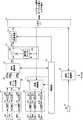
FIG. 1 is an external view of a video conference apparatus, and FIG. 2 is a block diagram showing a configuration of the video conference apparatus. The video conference apparatus includes speakers SP1 to SP8, microphones M1 to M12, and a
スピーカSP1〜SP8は、直線状に配列されてスピーカアレイを構成する。マイクM1〜M12も直線状に配列されてマイクアレイを構成する。なお、本実施形態では、スピーカの個数を8個、マイクの個数を12個とする例を示すが、配列個数はこの例に限定するものではない。また、スピーカ、マイクの配列間隔は等間隔でなくともよい。 The speakers SP1 to SP8 are arranged in a straight line to constitute a speaker array. The microphones M1 to M12 are also arranged linearly to constitute a microphone array. In the present embodiment, an example is shown in which the number of speakers is eight and the number of microphones is twelve, but the number of arrangements is not limited to this example. Moreover, the arrangement intervals of the speakers and microphones do not have to be equal.
図2に示すように、テレビ会議装置は、上記スピーカSP1〜SP8、マイクM1〜M12、およびカメラ11に加え、入出力I/F12、画像データ処理部13、制御部14、A/D変換部15、収音ビーム生成部16、信号選択部17、エコーキャンセラ18、レベル調整回路19、放音制御部20、およびD/A変換部21を備えている。 As shown in FIG. 2, in addition to the speakers SP1 to SP8, the microphones M1 to M12, and the
制御部14は、例えばマイコン等により構成され、カメラ11、収音ビーム生成部16、信号選択部17、レベル調整回路19、および放音制御部20に接続されており、テレビ会議装置を統括的に制御する。例えばリモコン(図示せず)から入力されるユーザの操作に応じて、カメラ11の撮影範囲を設定したり、収音レベル、放音レベル等をコントロールする。また、後述するレベル調整回路19のレベル調整量を設定する。 The
入出力I/F12は、ネットワーク端子、オーディオ端子、ビデオ端子に接続されている。入出力I/F12は、これらの端子を介して相手先テレビ会議装置と音声、および映像を送受信する。ネットワーク端子を介して送受信する場合、ネットワーク通信データ形式からなる音声、および映像の各データを受信する。受信した映像データは画像データ処理部13に出力される。受信した音声データは、デジタル音声信号に変換されてエコーキャンセラ18、および放音制御部20に出力される。 The input / output I /
また、入出力I/F12は、画像データ処理部13から入力される映像データをネットワーク通信データ形式で相手先テレビ会議装置に送信し、レベル調整回路19から入力されるデジタル音声信号をネットワーク通信データ形式で相手先テレビ会議装置に送信する。 The input / output I /
カメラ11は、自装置の前に居る会議者が含まれる範囲を撮像して、映像信号を画像データ処理部13に出力する。カメラ11がパン、チルト、ズーム機能を搭載している場合、撮影範囲は制御部14によって設定される。その他、撮影設定(コントラスト等)も制御部14によって設定される。 The
画像データ処理部13は、カメラ11から入力された映像信号を映像データ(圧縮データ)に変換し、これを入出力I/F12に出力する。また、入出力I/F12から入力された映像データをエンコードして、映像信号としてモニタ2に出力する。 The image
マイクアレイの各マイクM1〜M12は、自装置の前に居る会議者(話者)の発声音を収音して収音音声信号を生成する。
A/D変換部15は、各マイクM1〜M12にそれぞれ対応して収音アンプ151、A/D変換器152を備えている。収音アンプ151は、収音音声信号を増幅し、A/D変換器152は、増幅された収音音声信号をデジタル音声信号に変換して、収音ビーム生成部16に出力する。Each of the microphones M1 to M12 of the microphone array collects a voice of a conference person (speaker) in front of its own device and generates a collected voice signal.
The A /
収音ビーム生成部16は、A/D変換部15から入力された各デジタル音声信号に対して所定の遅延処理を行った後合成し、特定の方向から到来する音声を強調した信号である収音ビーム信号MB1〜MB8を生成する。収音ビーム信号MB1〜MB8は、図3に示すように、マイクM1〜M12が設置された長尺面側で当該長尺面に沿ってそれぞれに異なる方向の音声を収音したものである。図3では、音声会議装置の前面に設置された長方形状の会議机を囲むように各話者が存在するため、最も傾いた方向の収音ビームの収音領域である収音ビーム領域MB11,MB18が音声会議装置に最も近い収音領域となる。一方、音声会議装置前面の中央方向の収音ビームの収音ビーム領域である収音ビーム領域MB14,MB15が音声会議装置に最も遠い収音ビーム領域となる。なお、収音ビームの数、領域の位置はこの例に限るものではない。制御部14が各デジタル音声信号の遅延量をコントロールすることで、収音ビーム領域を変更することができる。 The sound collection
信号選択部17は、収音ビーム信号MB1〜MB8のうち最もレベルの高い信号を選択し、その収音ビーム信号をメイン収音ビーム信号MSとしてエコーキャンセラ18に出力する。また、選択した収音ビーム信号を制御部14に通知する。 The
図4は、信号選択部17の主要構成を示すブロック図である。
信号選択部17は、BPF(バンドパスフィルタ)171、全波整流回路172、ピーク検出回路173、レベル比較器174、および信号選択回路175を備えている。FIG. 4 is a block diagram illustrating a main configuration of the
The
BPF171は、人の音声の主成分帯域を通過帯域とするバンドパスフィルタであり、収音ビーム信号MB1〜MB8を帯域通過フィルタ処理して、全波整流回路172に出力する。全波整流回路172は、収音ビーム信号MB1〜MB8を全波整流(絶対値化)し、ピーク検出回路173は、全波整流された収音ビーム信号MB1〜MB8のピーク検出を行い、ピーク値データPs1〜Ps8を出力する。レベル比較器174は、ピーク値データPs1〜Ps8を比較して、最も高いレベルのピーク値データPsに対応する収音ビーム信号を選択する選択指示データを信号選択回路175に与える。また、レベル比較器174は、最も高いレベルのピーク値データPsに対応する収音ビーム信号を選択する選択指示データを制御部14にも与える。信号選択回路175は、選択指示データが示す収音ビーム信号を選択し、メイン収音ビーム信号MSとしてエコーキャンセラ18に出力する。
これは、発話者が存在する収音領域に対応する収音ビーム信号の信号レベルが他の領域に対応する収音ビーム信号の信号レベルよりも高いことを利用している。The
This utilizes the fact that the signal level of the sound collecting beam signal corresponding to the sound collecting region where the speaker is present is higher than the signal level of the sound collecting beam signal corresponding to the other region.
制御部14は、レベル比較器174から入力した選択指示データに基づいて、カメラ11の撮影設定を変更する。例えば、選択された収音ビーム信号の対応する領域の映像を撮影するように、カメラ11のパン、チルト、ズームを設定する。また、制御部14は、選択指示データに基づいて、レベル調整回路19のレベル調整量を設定する。 The
エコーキャンセラ18は、適応型フィルタ181とポストプロセッサ182とを備えている。適応型フィルタ181は、入力音声信号に基づいて、スピーカアレイからマイクアレイに回り込む回帰音声信号を擬似した擬似回帰音信号を生成する。ポストプロセッサ182は、信号選択部17から出力されるメイン収音ビーム信号MSから擬似回帰音信号を減算して、出力音声信号MSsとしてレベル調整回路19に出力する。これによりエコー成分を消去する。また、出力音声信号MSsは適応型フィルタ181に入力され、適応型フィルタ181は、入力された出力音声信号に基づいてエコー成分を消去するようにフィルタ係数を更新する。 The
図5は、レベル調整回路19の構成を示すブロック図である。レベル調整回路19は、入力ゲインコントローラ191、コンプレッサ192、および出力ゲインコントローラ193を備えている。入力ゲインコントローラ191は、レベル調整回路19に入力された音声信号のゲインを調整する。 FIG. 5 is a block diagram showing the configuration of the
コンプレッサ192は、入力ゲインコントローラ191から入力された音声信号のレベルを検出し、レベル調整を行う。具体的には、図6に示すように、入力音声信号に対して予め定められた比で増幅、または減衰を行い、出力を行うものである。入力に対する出力の比(特性)は制御部14により設定される。 The
図6は、入力音声信号と出力音声信号のレベル比を表した図である。同図に示すグラフの横軸は入力信号(IN)のレベルを示し、縦軸は出力信号(OUT)のレベルを示す。同図においては入力音声信号に対する出力音声信号のレベル比の設定(特性)を3種類示している。特性1は、入力音声信号に対する出力音声信号のレベル比が常に1対1である。すなわち、入力音声信号を増幅も減衰もせずに出力する設定である。 FIG. 6 is a diagram showing the level ratio between the input audio signal and the output audio signal. The horizontal axis of the graph shown in the figure represents the level of the input signal (IN), and the vertical axis represents the level of the output signal (OUT). The figure shows three types of setting (characteristics) of the level ratio of the output audio signal to the input audio signal. In
特性2は、入力音声信号が無音(−∞dB)〜所定のレベルa1の間は入力音声信号のレベル増加量よりも出力音声信号のレベル増加量が大きくなるように設定されている。入力音声信号のレベルがa1であるとき、出力音声信号のレベルはb2(a1<b2)となる。入力音声信号が所定のレベルa1(dB)〜a2(dB)の間は入力音声信号のレベル増加量に対する出力音声信号のレベル増加量が1対1となる。つまり、特性1のレベル比と並行する。入力音声信号のレベルがa2であるとき、出力音声信号のレベルはb4(a2<b4)となる。入力音声信号が所定のレベルa2〜最大(0dB)の間は入力音声信号のレベル増加量よりも出力音声信号のレベル増加量が小さくなるように設定されている。入力音声信号のレベルが0dBであるとき、出力音声信号のレベルも0dBになるように設定される。 The characteristic 2 is set so that the level increase amount of the output sound signal is larger than the level increase amount of the input sound signal when the input sound signal is silent (−∞ dB) to a predetermined level a1. When the level of the input audio signal is a1, the level of the output audio signal is b2 (a1 <b2). When the input audio signal is between the predetermined levels a1 (dB) to a2 (dB), the level increase of the output audio signal is 1: 1 with respect to the level increase of the input audio signal. That is, it is parallel to the level ratio of
特性3は、特性2と同じ傾向であるが、信号増幅量が小さく抑えられている。入力音声信号が無音(−∞dB)〜所定のレベルa1の間は入力音声信号のレベル増加量よりも出力音声信号のレベル増加量が大きくなるように設定されている。入力音声信号のレベルがa1であるとき、出力音声信号のレベルはb1(a1<b1<b2)となる。入力音声信号が所定のレベルa1(dB)〜a2(dB)の間は入力音声信号のレベル増加量に対する出力音声信号のレベル増加量が1対1となる。つまり、特性1、特性2のレベル比と並行する。入力音声信号のレベルがa2であるとき、出力音声信号のレベルはb3(a2<b3<b4)となる。入力音声信号が所定のレベルa2〜最大(0dB)の間は入力音声信号のレベル増加量よりも出力音声信号のレベル増加量が小さくなるように設定されている。入力音声信号のレベルが0dBであるとき、出力音声信号のレベルも0dBになるように設定される。 The characteristic 3 has the same tendency as the characteristic 2, but the signal amplification amount is kept small. When the input audio signal is silent (−∞ dB) to a predetermined level a1, the level increase amount of the output audio signal is set larger than the level increase amount of the input audio signal. When the level of the input audio signal is a1, the level of the output audio signal is b1 (a1 <b1 <b2). When the input audio signal is between the predetermined levels a1 (dB) to a2 (dB), the level increase of the output audio signal is 1: 1 with respect to the level increase of the input audio signal. That is, it is parallel to the level ratio of characteristic 1 and characteristic 2. When the level of the input audio signal is a2, the level of the output audio signal is b3 (a2 <b3 <b4). While the input audio signal is between the predetermined level a2 and the maximum (0 dB), the level increase amount of the output audio signal is set smaller than the level increase amount of the input audio signal. When the input audio signal level is 0 dB, the output audio signal level is also set to 0 dB.
制御部14は、これらの特性を示すテーブルを内蔵メモリ(図示せず)に記録しており、これらの特性のいずれかをコンプレッサ192に設定する。制御部14は、レベル比較器174から入力した選択指示データに基づいて、コンプレッサ192に設定すべき特性を以下のようにして決定する。すなわち、図3において音声会議装置から最も近い収音ビーム領域であるMB11,MB18に対応する収音ビーム信号が選択指示データに含まれているとき、上記特性1を選択する。音声会議装置から最も遠い中央の収音ビーム領域であるMB14,MB15に対応する収音ビーム信号が選択指示データに含まれているとき、上記特性2を選択する。また、音声会議装置からの距離がその中間に位置する収音ビーム領域であるMB12,MB13,MB16,MB17に対応する収音ビーム信号が選択指示データに含まれているとき、上記特性3を選択する。 The
これは、話者の位置による収音レベルの変化を抑えるためである。音声会議装置からの距離が遠くなるほど、同じ発話音量で発言されたとしても収音される信号レベルは低下する。そのため、音声会議装置からの距離が遠くなるほど、コンプレッサ192で入力音声信号を増幅するように設定する。また、制御部14は、コンプレッサ192に入力される入力音声信号が図6におけるレベルa1(dB)〜a2(dB)の間となるように、入力ゲインコントローラ191のゲインを設定する。制御部14は、入力ゲインコントローラ191を介して出力音声信号MSsのレベルを検出し、出力音声信号MSsのレベルが上記a1未満であれば、a1以上となるように入力ゲインコントローラ191のゲインを設定する。また、出力音声信号MSsのレベルが上記a2以上であれば、a2未満となるように入力ゲインコントローラ191のゲインを設定する。すなわち、コンプレッサ192の出力が聴覚上自然に聞こえる領域である、入力音声信号のレベル増加量に対する出力音声信号のレベル増加量が1対1となる設定領域になるように入力ゲインコントローラ191のゲインを設定する。 This is to suppress a change in sound collection level due to the position of the speaker. As the distance from the audio conference apparatus increases, the level of the signal that is collected decreases even if the speech is spoken at the same speech volume. Therefore, the
出力ゲインコントローラ193は、コンプレッサ192の出力レベルが高すぎる場合に、これを抑制する。出力ゲインコントローラ193のゲインは制御部14により設定される。制御部14は、出力音声信号MSsのレベルがa1未満であればa1以上となるように入力ゲインコントローラ191のゲインを設定するが、あまりにもゲインを大きくすると(例えば2倍程度にすると)聴覚的に不自然となる。そこで、制御部14は、入力ゲインコントローラ191に設定したゲインを補正するように、出力ゲインコントローラ193のゲインを設定する。例えば入力ゲインコントローラ191のゲインを2倍に設定した場合、出力ゲインコントローラ193のゲインを0.5倍に設定する。 The
なお、コンプレッサの特性の数、およびレベルは図6の例に限定されるものではない。音声会議装置の使用状況(ビームの数、収音ビーム領域との距離)に応じて適宜設定すればよい。また、図6では、入力音声信号を増幅して出力する例を示しているが、減衰して出力する特性を設定してもよい。 Note that the number and level of the characteristics of the compressor are not limited to the example of FIG. What is necessary is just to set suitably according to the use condition (the number of beams, distance with a sound collection beam area | region) of an audio conference apparatus. Further, FIG. 6 shows an example in which the input audio signal is amplified and output, but the characteristic of attenuating and outputting may be set.
放音制御部20は、入力音声信号に所定の遅延処理を行い、D/A変換部21における各D/Aコンバータ211に入力する。各D/Aコンバータ211は、入力された音声信号をアナログ音声信号に変換し、AMP212に入力する。AMP212は、アナログ音声信号を増幅してスピーカSP1〜SP8に入力し、スピーカSP1〜SP8は、音声を放音する。 The sound
放音制御部20は、スピーカアレイの各スピーカに入力する音声信号に遅延処理を行うことで、所定方向に強い指向性を有する放音ビームを形成することができる。また、所定位置に焦点を結ぶように放音ビームを形成することもできる。各スピーカは、焦点との実距離がそれぞれ異なるが、これらのスピーカを焦点から等距離に配列したようなタイミングで放音されるように音声信号を遅延すればよい。 The sound
なお、図3では8つの収音ビーム領域MB11〜MB18の音声を収音する例について示したが、図7に示すように、音声会議装置の前面に並行して、4つの収音ビームを形成してもよい。図7は、音声会議装置の前面の会議机に並行して会議参加者が存在する場合の例を示す。この場合、収音ビーム領域MB21〜MB24は、それぞれ音声会議装置との距離が略等しくなる。この場合、上述のように中央の収音ビーム領域に対応する収音ビーム信号を増幅すると、これらの収音領域で発話した音声だけが大きくなってしまう。そこで、制御部14は、コンプレッサ192の設定を、上記特性3、または特性1に変更するように設定する。すなわち、制御部14は、図4においてレベル比較器174から選択指示データを受信したとき、その収音ビームの収音レベル(またはエネルギ)を取得し、この平均値を算出する。この平均値をメモリ(図示せず)に記憶しておく。制御部14は、この平均値が所定のレベルを超えた場合、または各収音ビームの平均値を比較し、中央方向の収音ビームの平均値が他の収音ビームよりも高く(例えば1.5倍程度)なった場合、会議参加者が音声会議装置の前面に並行して存在するとみなし、コンプレッサ192の設定を、上記特性3、または特性1に変更するように設定する。これにより、一部発話音声だけが大きくなることを防止する。 Although FIG. 3 shows an example in which voices in eight sound collecting beam areas MB11 to MB18 are picked up, as shown in FIG. 7, four sound collecting beams are formed in parallel with the front face of the audio conference apparatus. May be. FIG. 7 shows an example in which conference participants exist in parallel with the conference desk on the front surface of the audio conference apparatus. In this case, the sound collection beam areas MB21 to MB24 are approximately equal in distance to the audio conference apparatus. In this case, as described above, if the sound collection beam signal corresponding to the central sound collection beam region is amplified, only the speech uttered in these sound collection regions is increased. Therefore, the
なお、音声会議装置にユーザインタフェース(ボタンなど)を設置し、ユーザが手動で設定を変更するようにしてもよい。 Note that a user interface (such as a button) may be installed in the audio conference apparatus, and the user may manually change the setting.
11−カメラ
SP1〜SP8−スピーカ
M1〜M12−マイク11-Cameras SP1-SP8-Speakers M1-M12-Microphone
Claims (4)
Translated fromJapanese前記収音部は、複数のマイクを配列してなるマイクアレイと、複数の方向に対して収音ビームを形成するとともに、各収音ビーム強度を比較することで話者方位を同定し、話者方位に対応する収音ビームを選択し、この選択した収音ビームを収音信号として出力する収音制御部と、からなり、
外部から入力された入力信号を信号処理し、前記放音部に入力する入力信号処理部と、
前記収音信号のレベルを減衰、または増幅するレベル調整回路と、
前記レベル調整回路の調整量を前記話者方位毎に記憶する設定テーブルと、
前記収音制御部から同定した話者方位を入力し、前記設定テーブルを読み出して該話者方位に対応する調整量を前記レベル調整回路に設定する制御部と、
を備えたテレビ会議装置。A video conferencing apparatus provided with a camera that shoots video, a sound emitting unit that emits sound, and a sound collecting unit that collects sound at close positions,
The sound collection unit forms a sound collection beam in a plurality of directions with a microphone array in which a plurality of microphones are arranged, and compares the sound collection beam intensities to identify the speaker direction, A sound collection control unit that selects a sound collection beam corresponding to the person's direction and outputs the selected sound collection beam as a sound collection signal;
An input signal processing unit that processes an input signal input from the outside and inputs the signal to the sound emitting unit;
A level adjustment circuit for attenuating or amplifying the level of the collected sound signal;
A setting table for storing the adjustment amount of the level adjustment circuit for each speaker orientation;
A controller that inputs the speaker orientation identified from the sound collection controller, reads the setting table, and sets an adjustment amount corresponding to the speaker orientation in the level adjustment circuit;
Video conferencing equipment.
前記制御部は、前記レベル調整回路の調整量として前記コンプレッサの特性を設定するとともに、前記収音信号のレベルを検出し、その収音信号のレベルに基づいて、前記入力ゲイン調整部のゲイン調整量を設定する請求項1に記載のテレビ会議装置。The level adjustment circuit includes a compressor that attenuates or amplifies the collected sound signal, and an input gain adjustment unit that adjusts the gain of the compressor.
The control unit sets the characteristics of the compressor as an adjustment amount of the level adjustment circuit, detects the level of the sound pickup signal, and adjusts the gain of the input gain adjustment unit based on the level of the sound pickup signal The video conference apparatus according to claim 1, wherein an amount is set.
各収音ビームの時間平均値が所定のレベルを超えた場合、または各収音ビームの時間平均値を比較して特定の収音ビームの時間平均値が所定値以上大きい場合、その収音ビームの話者方位に対応する調整量を下げる設定とする請求項1、または請求項2に記載のテレビ会議装置。The control unit calculates a time average value by detecting a level of the sound collecting beam when the sound collecting control unit selects the sound collecting beam,
When the time average value of each sound collecting beam exceeds a predetermined level, or when the time average value of each sound collecting beam is compared with the time average value of each sound collecting beam, the sound collecting beam The video conference apparatus according to claim 1, wherein the adjustment amount corresponding to the speaker direction is set to be lowered.
Priority Applications (1)
| Application Number | Priority Date | Filing Date | Title |
|---|---|---|---|
| JP2007158776AJP2008312002A (en) | 2007-06-15 | 2007-06-15 | Television conference apparatus |
Applications Claiming Priority (1)
| Application Number | Priority Date | Filing Date | Title |
|---|---|---|---|
| JP2007158776AJP2008312002A (en) | 2007-06-15 | 2007-06-15 | Television conference apparatus |
Publications (1)
| Publication Number | Publication Date |
|---|---|
| JP2008312002Atrue JP2008312002A (en) | 2008-12-25 |
Family
ID=40239188
Family Applications (1)
| Application Number | Title | Priority Date | Filing Date |
|---|---|---|---|
| JP2007158776APendingJP2008312002A (en) | 2007-06-15 | 2007-06-15 | Television conference apparatus |
Country Status (1)
| Country | Link |
|---|---|
| JP (1) | JP2008312002A (en) |
Cited By (26)
| Publication number | Priority date | Publication date | Assignee | Title |
|---|---|---|---|---|
| JP2009017343A (en)* | 2007-07-06 | 2009-01-22 | Yamaha Corp | Sound pickup device |
| JP2010206298A (en)* | 2009-02-27 | 2010-09-16 | Sony Corp | Recording apparatus, recording method, audio signal correction circuit, and program |
| WO2011048813A1 (en)* | 2009-10-21 | 2011-04-28 | パナソニック株式会社 | Sound processing apparatus, sound processing method and hearing aid |
| JP2015220655A (en)* | 2014-05-20 | 2015-12-07 | 三菱電機インフォメーションネットワーク株式会社 | Inter-long distance point bidirectional communication system and inter-long distance point bidirectional communication method |
| US10367948B2 (en) | 2017-01-13 | 2019-07-30 | Shure Acquisition Holdings, Inc. | Post-mixing acoustic echo cancellation systems and methods |
| USD865723S1 (en) | 2015-04-30 | 2019-11-05 | Shure Acquisition Holdings, Inc | Array microphone assembly |
| CN114007168A (en)* | 2021-11-03 | 2022-02-01 | 长沙楚风数码科技有限公司 | Intelligent audio control system and method |
| USD944776S1 (en) | 2020-05-05 | 2022-03-01 | Shure Acquisition Holdings, Inc. | Audio device |
| US11297426B2 (en) | 2019-08-23 | 2022-04-05 | Shure Acquisition Holdings, Inc. | One-dimensional array microphone with improved directivity |
| US11297423B2 (en) | 2018-06-15 | 2022-04-05 | Shure Acquisition Holdings, Inc. | Endfire linear array microphone |
| US11303981B2 (en) | 2019-03-21 | 2022-04-12 | Shure Acquisition Holdings, Inc. | Housings and associated design features for ceiling array microphones |
| US11302347B2 (en) | 2019-05-31 | 2022-04-12 | Shure Acquisition Holdings, Inc. | Low latency automixer integrated with voice and noise activity detection |
| US11310596B2 (en) | 2018-09-20 | 2022-04-19 | Shure Acquisition Holdings, Inc. | Adjustable lobe shape for array microphones |
| US11438691B2 (en) | 2019-03-21 | 2022-09-06 | Shure Acquisition Holdings, Inc. | Auto focus, auto focus within regions, and auto placement of beamformed microphone lobes with inhibition functionality |
| US11445294B2 (en) | 2019-05-23 | 2022-09-13 | Shure Acquisition Holdings, Inc. | Steerable speaker array, system, and method for the same |
| CN115151858A (en)* | 2020-02-17 | 2022-10-04 | Tk&H控股股份有限公司 | Hearing aid systems that can be integrated into eyeglass frames |
| US11523212B2 (en) | 2018-06-01 | 2022-12-06 | Shure Acquisition Holdings, Inc. | Pattern-forming microphone array |
| US11552611B2 (en) | 2020-02-07 | 2023-01-10 | Shure Acquisition Holdings, Inc. | System and method for automatic adjustment of reference gain |
| US11558693B2 (en) | 2019-03-21 | 2023-01-17 | Shure Acquisition Holdings, Inc. | Auto focus, auto focus within regions, and auto placement of beamformed microphone lobes with inhibition and voice activity detection functionality |
| US11678109B2 (en) | 2015-04-30 | 2023-06-13 | Shure Acquisition Holdings, Inc. | Offset cartridge microphones |
| US11706562B2 (en) | 2020-05-29 | 2023-07-18 | Shure Acquisition Holdings, Inc. | Transducer steering and configuration systems and methods using a local positioning system |
| US11785380B2 (en) | 2021-01-28 | 2023-10-10 | Shure Acquisition Holdings, Inc. | Hybrid audio beamforming system |
| US12028678B2 (en) | 2019-11-01 | 2024-07-02 | Shure Acquisition Holdings, Inc. | Proximity microphone |
| US12250526B2 (en) | 2022-01-07 | 2025-03-11 | Shure Acquisition Holdings, Inc. | Audio beamforming with nulling control system and methods |
| US12289584B2 (en) | 2021-10-04 | 2025-04-29 | Shure Acquisition Holdings, Inc. | Networked automixer systems and methods |
| CN120050385A (en)* | 2025-03-07 | 2025-05-27 | 沈阳创高天誉科技有限公司 | Audio and video signal communication management method and system |
Citations (6)
| Publication number | Priority date | Publication date | Assignee | Title |
|---|---|---|---|---|
| JPH05301542A (en)* | 1992-04-28 | 1993-11-16 | Pioneer Electron Corp | On-vehicle physical feeling sound device |
| JPH0983988A (en)* | 1995-09-11 | 1997-03-28 | Nec Eng Ltd | Video conference system |
| JPH09275533A (en)* | 1996-04-08 | 1997-10-21 | Sony Corp | Signal processor |
| JP2000059270A (en)* | 1998-08-14 | 2000-02-25 | Nec Corp | Sound echo canceler |
| JP2004147205A (en)* | 2002-10-25 | 2004-05-20 | Fuji Photo Film Co Ltd | Image and sound recorder |
| JP2007124140A (en)* | 2005-10-26 | 2007-05-17 | Yamaha Corp | Photographing device and communication conference system |
- 2007
- 2007-06-15JPJP2007158776Apatent/JP2008312002A/enactivePending
Patent Citations (6)
| Publication number | Priority date | Publication date | Assignee | Title |
|---|---|---|---|---|
| JPH05301542A (en)* | 1992-04-28 | 1993-11-16 | Pioneer Electron Corp | On-vehicle physical feeling sound device |
| JPH0983988A (en)* | 1995-09-11 | 1997-03-28 | Nec Eng Ltd | Video conference system |
| JPH09275533A (en)* | 1996-04-08 | 1997-10-21 | Sony Corp | Signal processor |
| JP2000059270A (en)* | 1998-08-14 | 2000-02-25 | Nec Corp | Sound echo canceler |
| JP2004147205A (en)* | 2002-10-25 | 2004-05-20 | Fuji Photo Film Co Ltd | Image and sound recorder |
| JP2007124140A (en)* | 2005-10-26 | 2007-05-17 | Yamaha Corp | Photographing device and communication conference system |
Cited By (46)
| Publication number | Priority date | Publication date | Assignee | Title |
|---|---|---|---|---|
| JP2009017343A (en)* | 2007-07-06 | 2009-01-22 | Yamaha Corp | Sound pickup device |
| JP2010206298A (en)* | 2009-02-27 | 2010-09-16 | Sony Corp | Recording apparatus, recording method, audio signal correction circuit, and program |
| US8462964B2 (en) | 2009-02-27 | 2013-06-11 | Sony Corporation | Recording apparatus, recording method, audio signal correction circuit, and program |
| WO2011048813A1 (en)* | 2009-10-21 | 2011-04-28 | パナソニック株式会社 | Sound processing apparatus, sound processing method and hearing aid |
| CN102549661A (en)* | 2009-10-21 | 2012-07-04 | 松下电器产业株式会社 | Sound processing apparatus, sound processing method and hearing aid |
| CN102549661B (en)* | 2009-10-21 | 2013-10-09 | 松下电器产业株式会社 | Sound processing device, sound processing method and hearing aid |
| US8755546B2 (en) | 2009-10-21 | 2014-06-17 | Pansonic Corporation | Sound processing apparatus, sound processing method and hearing aid |
| JP2015220655A (en)* | 2014-05-20 | 2015-12-07 | 三菱電機インフォメーションネットワーク株式会社 | Inter-long distance point bidirectional communication system and inter-long distance point bidirectional communication method |
| US12262174B2 (en) | 2015-04-30 | 2025-03-25 | Shure Acquisition Holdings, Inc. | Array microphone system and method of assembling the same |
| USD865723S1 (en) | 2015-04-30 | 2019-11-05 | Shure Acquisition Holdings, Inc | Array microphone assembly |
| USD940116S1 (en) | 2015-04-30 | 2022-01-04 | Shure Acquisition Holdings, Inc. | Array microphone assembly |
| US11678109B2 (en) | 2015-04-30 | 2023-06-13 | Shure Acquisition Holdings, Inc. | Offset cartridge microphones |
| US11310592B2 (en) | 2015-04-30 | 2022-04-19 | Shure Acquisition Holdings, Inc. | Array microphone system and method of assembling the same |
| US11832053B2 (en) | 2015-04-30 | 2023-11-28 | Shure Acquisition Holdings, Inc. | Array microphone system and method of assembling the same |
| US12309326B2 (en) | 2017-01-13 | 2025-05-20 | Shure Acquisition Holdings, Inc. | Post-mixing acoustic echo cancellation systems and methods |
| US10367948B2 (en) | 2017-01-13 | 2019-07-30 | Shure Acquisition Holdings, Inc. | Post-mixing acoustic echo cancellation systems and methods |
| US11477327B2 (en) | 2017-01-13 | 2022-10-18 | Shure Acquisition Holdings, Inc. | Post-mixing acoustic echo cancellation systems and methods |
| US11800281B2 (en) | 2018-06-01 | 2023-10-24 | Shure Acquisition Holdings, Inc. | Pattern-forming microphone array |
| US11523212B2 (en) | 2018-06-01 | 2022-12-06 | Shure Acquisition Holdings, Inc. | Pattern-forming microphone array |
| US11770650B2 (en) | 2018-06-15 | 2023-09-26 | Shure Acquisition Holdings, Inc. | Endfire linear array microphone |
| US11297423B2 (en) | 2018-06-15 | 2022-04-05 | Shure Acquisition Holdings, Inc. | Endfire linear array microphone |
| US11310596B2 (en) | 2018-09-20 | 2022-04-19 | Shure Acquisition Holdings, Inc. | Adjustable lobe shape for array microphones |
| US11438691B2 (en) | 2019-03-21 | 2022-09-06 | Shure Acquisition Holdings, Inc. | Auto focus, auto focus within regions, and auto placement of beamformed microphone lobes with inhibition functionality |
| US12284479B2 (en) | 2019-03-21 | 2025-04-22 | Shure Acquisition Holdings, Inc. | Auto focus, auto focus within regions, and auto placement of beamformed microphone lobes with inhibition functionality |
| US11303981B2 (en) | 2019-03-21 | 2022-04-12 | Shure Acquisition Holdings, Inc. | Housings and associated design features for ceiling array microphones |
| US11558693B2 (en) | 2019-03-21 | 2023-01-17 | Shure Acquisition Holdings, Inc. | Auto focus, auto focus within regions, and auto placement of beamformed microphone lobes with inhibition and voice activity detection functionality |
| US11778368B2 (en) | 2019-03-21 | 2023-10-03 | Shure Acquisition Holdings, Inc. | Auto focus, auto focus within regions, and auto placement of beamformed microphone lobes with inhibition functionality |
| US12425766B2 (en) | 2019-03-21 | 2025-09-23 | Shure Acquisition Holdings, Inc. | Auto focus, auto focus within regions, and auto placement of beamformed microphone lobes with inhibition and voice activity detection functionality |
| US11445294B2 (en) | 2019-05-23 | 2022-09-13 | Shure Acquisition Holdings, Inc. | Steerable speaker array, system, and method for the same |
| US11800280B2 (en) | 2019-05-23 | 2023-10-24 | Shure Acquisition Holdings, Inc. | Steerable speaker array, system and method for the same |
| US11688418B2 (en) | 2019-05-31 | 2023-06-27 | Shure Acquisition Holdings, Inc. | Low latency automixer integrated with voice and noise activity detection |
| US11302347B2 (en) | 2019-05-31 | 2022-04-12 | Shure Acquisition Holdings, Inc. | Low latency automixer integrated with voice and noise activity detection |
| US11750972B2 (en) | 2019-08-23 | 2023-09-05 | Shure Acquisition Holdings, Inc. | One-dimensional array microphone with improved directivity |
| US11297426B2 (en) | 2019-08-23 | 2022-04-05 | Shure Acquisition Holdings, Inc. | One-dimensional array microphone with improved directivity |
| US12028678B2 (en) | 2019-11-01 | 2024-07-02 | Shure Acquisition Holdings, Inc. | Proximity microphone |
| US11552611B2 (en) | 2020-02-07 | 2023-01-10 | Shure Acquisition Holdings, Inc. | System and method for automatic adjustment of reference gain |
| JP2023514462A (en)* | 2020-02-17 | 2023-04-05 | ティーケーアンドエイチ ホールディング エーエス | Hearing aid system that can be integrated into the spectacle frame |
| CN115151858A (en)* | 2020-02-17 | 2022-10-04 | Tk&H控股股份有限公司 | Hearing aid systems that can be integrated into eyeglass frames |
| USD944776S1 (en) | 2020-05-05 | 2022-03-01 | Shure Acquisition Holdings, Inc. | Audio device |
| US11706562B2 (en) | 2020-05-29 | 2023-07-18 | Shure Acquisition Holdings, Inc. | Transducer steering and configuration systems and methods using a local positioning system |
| US12149886B2 (en) | 2020-05-29 | 2024-11-19 | Shure Acquisition Holdings, Inc. | Transducer steering and configuration systems and methods using a local positioning system |
| US11785380B2 (en) | 2021-01-28 | 2023-10-10 | Shure Acquisition Holdings, Inc. | Hybrid audio beamforming system |
| US12289584B2 (en) | 2021-10-04 | 2025-04-29 | Shure Acquisition Holdings, Inc. | Networked automixer systems and methods |
| CN114007168A (en)* | 2021-11-03 | 2022-02-01 | 长沙楚风数码科技有限公司 | Intelligent audio control system and method |
| US12250526B2 (en) | 2022-01-07 | 2025-03-11 | Shure Acquisition Holdings, Inc. | Audio beamforming with nulling control system and methods |
| CN120050385A (en)* | 2025-03-07 | 2025-05-27 | 沈阳创高天誉科技有限公司 | Audio and video signal communication management method and system |
Similar Documents
| Publication | Publication Date | Title |
|---|---|---|
| JP2008312002A (en) | Television conference apparatus | |
| JP2008288785A (en) | Video conference apparatus | |
| JP5028944B2 (en) | Audio conference device and audio conference system | |
| US9984675B2 (en) | Voice controlled audio recording system with adjustable beamforming | |
| US9226070B2 (en) | Directional sound source filtering apparatus using microphone array and control method thereof | |
| EP2011366B1 (en) | Sound pickup device and voice conference apparatus | |
| JP5855571B2 (en) | Audio zoom | |
| US9269350B2 (en) | Voice controlled audio recording or transmission apparatus with keyword filtering | |
| US8548176B2 (en) | Apparatus including microphone arrangements | |
| JP3972921B2 (en) | Voice collecting device and echo cancellation processing method | |
| JP2007274463A (en) | Remote conference apparatus | |
| CN101379870A (en) | Audio conference equipment | |
| JP4411959B2 (en) | Audio collection / video imaging equipment | |
| JP4479227B2 (en) | Audio pickup / video imaging apparatus and imaging condition determination method | |
| JP3932928B2 (en) | Loudspeaker | |
| JP4639639B2 (en) | Microphone signal generation method and communication apparatus | |
| JP2007329753A (en) | Voice communication device and voice communication device | |
| JP2009212927A (en) | Sound collecting apparatus | |
| JP2005086363A (en) | Calling device | |
| JP2008034979A (en) | Voice communication device and voice communication system | |
| JP2008017126A (en) | Voice conference system | |
| JPH10155107A (en) | Video camera with built-in microphone | |
| JP2008177745A (en) | Sound collection and radiation system | |
| JP2007258951A (en) | Teleconference equipment | |
| JP4470413B2 (en) | Microphone / speaker integrated configuration / communication device |
Legal Events
| Date | Code | Title | Description |
|---|---|---|---|
| A621 | Written request for application examination | Free format text:JAPANESE INTERMEDIATE CODE: A621 Effective date:20100421 | |
| A131 | Notification of reasons for refusal | Free format text:JAPANESE INTERMEDIATE CODE: A131 Effective date:20120214 | |
| A02 | Decision of refusal | Free format text:JAPANESE INTERMEDIATE CODE: A02 Effective date:20120703 |