JP2008310137A - Support tool for guide display unit, and installation method therefor - Google Patents
Support tool for guide display unit, and installation method thereforDownload PDFInfo
- Publication number
- JP2008310137A JP2008310137AJP2007158859AJP2007158859AJP2008310137AJP 2008310137 AJP2008310137 AJP 2008310137AJP 2007158859 AJP2007158859 AJP 2007158859AJP 2007158859 AJP2007158859 AJP 2007158859AJP 2008310137 AJP2008310137 AJP 2008310137A
- Authority
- JP
- Japan
- Prior art keywords
- stand
- guide
- indicator
- guide display
- connector
- Prior art date
- Legal status (The legal status is an assumption and is not a legal conclusion. Google has not performed a legal analysis and makes no representation as to the accuracy of the status listed.)
- Pending
Links
- 238000009434installationMethods0.000titleclaimsabstractdescription29
- 238000000034methodMethods0.000titleclaimsdescription20
- 239000000725suspensionSubstances0.000claimsdescription20
- 238000003780insertionMethods0.000claimsdescription5
- 230000037431insertionEffects0.000claimsdescription5
- 230000000694effectsEffects0.000description3
- 238000002438flame photometric detectionMethods0.000description3
- 230000003796beautyEffects0.000description1
- 238000004891communicationMethods0.000description1
- 238000010276constructionMethods0.000description1
- 238000010586diagramMethods0.000description1
- 230000001771impaired effectEffects0.000description1
- 238000007689inspectionMethods0.000description1
- 239000004973liquid crystal related substanceSubstances0.000description1
- 230000002093peripheral effectEffects0.000description1
- 230000003014reinforcing effectEffects0.000description1
Images


Landscapes
- Devices For Indicating Variable Information By Combining Individual Elements (AREA)
Abstract
Description
Translated fromJapanese本発明は、案内表示器の支持具及び設置工法に関する。 The present invention relates to a support for a guidance display and an installation method.
近時、液晶表示装置、プラズマ表示装置等の薄型平面表示装置の大型化、低廉化に伴い、鉄道向け案内表示器としても従来のLED表示装置に代え薄型平面表示装置を用いた案内表示器の実用化が進められつつある。
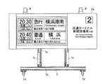
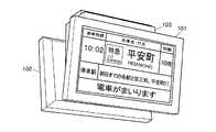
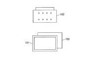
図9に示すように、薄型平面表示装置を用いた2つの案内表示器101,102が背合せに連結されて吊下げ設置される場合がある。かかる案内表示器101,102には、図9及び図10に示すような連結具103が用いられる。なお、汎用の薄型平面表示装置は屋内用を想定して構成されているため、これを用いた案内表示器101,102を駅プラットホーム等の半野外等に設置する場合、案内表示器101,102は、防塵防滴等のための筐体内に汎用の薄型平面表示装置を収めた構成を有する。
従来、このような案内表示器101,102の設置工法は、以下の工程によっていた。
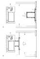
まず、図11(a)(b)に示すように、連結具103をリフトアップし予め梁等に固定されている吊下支柱等の取付具104に連結する。
次に、図11(b)(c)(d)に示すように、一方の案内表示器101と他方の案内表示器102をそれぞれ別々にリフトアップし、背部を連結具103に連結する。Recently, along with the increase in size and cost of thin flat display devices such as liquid crystal display devices and plasma display devices, a guide display device using a thin flat display device instead of a conventional LED display device is used as a guide display for railways. Practical use is being promoted.
As shown in FIG. 9, there are cases where two
Conventionally, the installation method of such
First, as shown in FIGS. 11 (a) and 11 (b), the
Next, as shown in FIGS. 11 (b), 11 (c) and 11 (d), one
以上のように、連結具103と2つの案内表示器101,102とを順にリフトアップし、上で組立てる工法が採られていた。
しかし、かかる工法によると、作業が煩雑であるという問題がある。
また、案内表示器101,102は、吊下げ設置用であるため、床置きに適した構造、強度を有さず、作業上の取り扱いを困難にさせるという問題がある。As described above, a construction method has been adopted in which the
However, this method has a problem that the work is complicated.
Further, since the
本発明は以上の従来技術における問題に鑑みてなされたものであって、薄型平面表示装置を用いた案内表示器の吊下げ設置の作業性を向上できる案内表示器の支持具及び設置工法を提供することを課題とする。 The present invention has been made in view of the above problems in the prior art, and provides a guide display support and an installation method capable of improving the workability of the guide display hanging installation using a thin flat display device. The task is to do.
以上の課題を解決するための請求項1記載の発明は、薄型平面表示装置を用いた案内表示器の背部に連結され、吊下げ支持される連結具と、
前記連結具に連結されて前記案内表示器を床置状態に支持すること、及び前記連結具から下方への移動により離脱することを可能に構成されたスタンドとを備えた案内表示器の支持具である。The invention according to
A support device for a guide display device, comprising: a stand connected to the connection device to support the guide display device in a floor-mounted state and to be detached from the connection device by moving downward. It is.
請求項2記載の発明は、前記連結具は、2つの前記案内表示器を背合せに連結可能に構成されている請求項1に記載の案内表示器の支持具である。 The invention according to
請求項3記載の発明は、前記連結具及び前記スタンドの側部に両者を互いに固定するボルトの挿入部が形成されている請求項2に記載の案内表示器の支持具である。 According to a third aspect of the present invention, there is provided a guide indicator supporting tool according to the second aspect, wherein a bolt insertion portion for fixing the connecting tool and the stand to each other is formed on the side part of the stand.
請求項4記載の発明は、前記スタンドは脚車を有する請求項1、請求項2又は請求項3に記載の案内表示器の支持具である。 According to a fourth aspect of the present invention, there is provided the guide indicator support according to the first, second, or third aspect, wherein the stand has a caster.
請求項5記載の発明は、請求項1から請求項4のうちいずれか一に記載の案内表示器の支持具を用いた案内表示器の設置工法であって、
前記連結具及び前記スタンドが連結されて該スタンドによって支持された前記案内表示器を設置現場に運搬する工程と、
前記スタンドに支持させた状態で前記スタンドごとに前記案内表示器をリフターによりリフトアップし、前記連結具を吊下げ状態に連結する工程と、
前記スタンドを前記連結具から離脱させる工程とを以上の記載順で備える案内表示器の設置工法である。The invention according to claim 5 is a guide indicator installation method using the guide indicator support tool according to any one of
Transporting the guidance indicator supported by the stand connected to the connector and the stand to an installation site;
Lifting up the guide indicator by a lifter for each stand in a state of being supported by the stand, and connecting the connector in a suspended state;
It is an installation method of a guidance indicator provided with the process of detaching the stand from the connector in the order described above.
本発明の案内表示器の支持具を用いれば、案内表示器のリフトアップ前に、スタンドをベースにして連結具、案内表示器を連結していくことによって、案内表示器及びその吊下げ用具の組立を容易にすることができ、組立の作業性が向上するという効果がある。
また、本発明の案内表示器の支持具を用いれば、案内表示器、連結具及びスタンドの組立後は、案内表示器に直接触れる必要は無くスタンド部分を扱うことによって案内表示器の取り回しが可能になり、案内表示器を傷付けたり変形させたりするおそれなく容易に取り扱うことができ、移動や点検、吊下げ設置など作業性が向上するという効果がある。
また、本発明の案内表示器の支持具を用いれば、スタンドごと案内表示器をリフトアップして吊下げ設置しても、スタンドは連結具から下方への移動により離脱するので、不要となったスタンドを容易に取り去ることができ、吊下げ設置の作業性を損なわないという効果がある。By using the support for the guide display of the present invention, before the lift of the guide display, by connecting the connecting tool and the guide display based on the stand, the guide display and its hanging tool Assembling can be facilitated, and assembling workability is improved.
In addition, if the guide indicator support tool of the present invention is used, it is not necessary to directly touch the guide indicator after assembly of the guide indicator, connector and stand, and the guide indicator can be handled by handling the stand portion. Therefore, the guidance display can be easily handled without fear of being damaged or deformed, and there is an effect that workability such as movement, inspection, and hanging installation is improved.
In addition, if the support device for the guide indicator of the present invention is used, even if the guide indicator is lifted up and suspended with the stand, the stand is removed by moving downward from the connecting device, which is no longer necessary. The stand can be easily removed, and the workability of the hanging installation is not impaired.
特に、連結具に2つの案内表示器が背合せに連結される場合は、案内表示器の背後方向への離脱は困難になるので、スタンドが連結具から下方への移動により離脱する構成が有効に働く。また、吊下げ物全体を薄型に構成できる。
また、同じく連結具に2つの案内表示器が背合せに連結される場合においては、案内表示器の背後方向からのボルトの挿入が困難になるので、連結具及びスタンドの側部に両者を互いに固定するボルトの挿入部が形成されている構成が有効である。
また、移動の容易のため、スタンドは脚車を有することが好ましいが、脚車を有さないスタンドを台車に載せて移動させてもよい。In particular, when two guide indicators are connected back-to-back to the connector, it is difficult to remove the guide indicator in the rear direction. Therefore, a configuration in which the stand is detached from the connector by moving downward is effective. To work. Moreover, the whole suspended object can be comprised thinly.
Similarly, when two guide indicators are connected back-to-back to the connector, it is difficult to insert bolts from behind the guide indicator. A configuration in which an insertion portion of a bolt to be fixed is formed is effective.
Moreover, although it is preferable that a stand has a caster for easy movement, you may move the stand which does not have a caster on a cart.
また、本発明の案内表示器の設置工法によれば、本発明の支持具を用い、連結具及びスタンドが連結されて該スタンドによって支持された案内表示器を設置現場に運搬するので、容易に運搬することができるとともに、工場での組立度を上げることができるという効果がある。
また、本発明の案内表示器の設置工法によれば、スタンドに支持させた状態でスタンドごとに案内表示器をリフターによりリフトアップし、連結具を吊下げ状態に連結するので、リフトアップが一度で済み、リフトアップ後の連結作業も連結具を吊下支柱などに吊下げ状態に連結する作業だけで済むので、工数が減り吊下げ設置の作業性が向上するという効果がある。
また、本発明の案内表示器の設置工法によれば、連結具を吊下げ状態に連結した後は、スタンドは連結具から下方への移動により離脱するので、不要なスタンドを容易に取り去ることができるという効果がある。In addition, according to the installation method of the guide display of the present invention, the support tool of the present invention is used, the connection tool and the stand are connected, and the guide display supported by the stand is transported to the installation site. It has the effect that it can be transported and the assembly level in the factory can be increased.
Further, according to the installation method of the guide indicator of the present invention, the guide indicator is lifted up by the lifter for each stand while being supported by the stand, and the connecting tool is connected to the suspended state. Since the connection work after the lift-up only needs to be performed by connecting the connection tool to the suspension column or the like in the suspended state, the number of steps is reduced and the workability of the suspension installation is improved.
In addition, according to the guide indicator installation method of the present invention, after the connecting tool is connected to the suspended state, the stand is detached from the connecting tool by moving downward, so that the unnecessary stand can be easily removed. There is an effect that can be done.
以下に本発明の一実施形態につき図面を参照して説明する。以下は本発明の一実施形態であって本発明を限定するものではない。 An embodiment of the present invention will be described below with reference to the drawings. The following is one embodiment of the present invention and does not limit the present invention.
本発明の一実施形態に係る案内表示器の吊下状態を示す斜視図を図1に、平面図を図2に示す。また、本発明の一実施形態に係る案内表示器の吊下及びスタンド連結状態を示す正面図を図3に、側面図を図4に、正面透視図を図5に示す。 FIG. 1 is a perspective view showing a suspended state of a guidance display according to an embodiment of the present invention, and FIG. 2 is a plan view thereof. FIG. 3 is a front view showing a suspended state and a stand connection state of the guide display according to the embodiment of the present invention, FIG. 4 is a side view, and FIG. 5 is a front perspective view.
図1〜図5に示すように、本実施形態に係る案内表示器の支持具は、2つの案内表示器を背合せに連結して吊下げ及び床置き状態に支持できるものである。本実施形態に係る案内表示器及びその支持具は、液晶表示装置等の薄型平面表示装置(フラットパネルディスプレイ:以下「FPD」という。)1a,1bと、前側筐体部品2a,2bと、後側筐体部品3a,3bと、背面取付フレーム4a,4bと、アングル調整連結具5a,5bとを各一対ずつ有し、さらに吊下連結具6と、スタンド7と、吊下支柱8,8とを備えて構成される。 As shown in FIG. 1 to FIG. 5, the support for the guidance display device according to the present embodiment can be supported in a suspended state and a floor-standing state by connecting two guide displays back to back. The guide display and its support according to the present embodiment include a thin flat display device (flat panel display: hereinafter referred to as “FPD”) 1a, 1b,
スタンド7は、ベースフレーム7bと、ベースフレーム7bに立設固定された門形フレーム7aと、補強部材7cと、ベースフレーム7bに付設された脚車7dとを備えて構成されている。図5に示すように、門形フレーム7aは、2つの柱部7a−2,3と、これらの頂部間に架設固定された上部梁部7a−1から構成されている。 The
吊下連結具6は、上部梁部6aと、下部梁部6bと、下垂柱部6c,6dとを備えて構成されている。下垂柱部6c,6dの上端が上部梁部6aに結合しており、上部梁部6aの両端は下垂柱部6c,6dに対して張り出している。下部梁部6bの両端が下垂柱部6c,6dの上端に近いその内側部に結合している。 The
吊下げ設置時、上部梁部6aは吊下支柱8,8の下端に連結固定される。なお、図5に示すように、上部梁部6aは、吊下支柱8,8から延出する配線12をそのまま通過させる孔を有し、背面取付フレーム4a,4bは配線挿入部11を有しており、配線12を配線挿入部11に挿入して案内表示器筐体内に配線12を通すことができる。
また、吊下連結具6にはサイドカバー13が取付可能となっている。サイドカバー13によって配線等を隠し美観を高めることができる。作業時にはサイドカバー13を取り外しておくことができる。At the time of suspension installation, the
Further, a
スタンド7の連結時、下部梁部6bはスタンド7の上部梁部7a−1上に互いの長手方向を一致させて重ね置かれ、下垂柱部6c,6dは、上部梁部7a−1の長手方向のそれぞれにおいて柱部7a−2,3の外側に隣接配置され、吊下連結具6は、門形フレーム7aの上部を挟むように配置される。この状態において、下垂柱部6c,6dに形成された孔と柱部7a−2,3に形成された雌ネジとが一致し、ボルト9を側方から挿入して吊下連結具6とスタンド7とを互いに締結固定することができる。 When the
このようにスタンド7に吊下連結具6を連結した後、吊下連結具6の両側に、アングル調整連結具5a,5bを、防振ゴム10を介して連結する。
次に、アングル調整連結具5a,5bに背面取付フレーム4a,4bを連結固定する。
次に、背面取付フレーム4a,4bの周縁部に後側筐体部品3a,3bの後面に形成された開口を合せて背面取付フレーム4a,4bに後側筐体部品3a,3bを固定する。
次に、背面取付フレーム4a,4bにFPD1a,1b及び電源装置、通信装置等の必要な装置を固定する。
次に、蓋をするようにして、後側筐体部品3a,3bに前側筐体部品2a,2bを連結する。
以上のような組立は、工場内で行う。After the
Next, the
Next, the
Next, necessary devices such as the
Next, the
The above assembly is performed in the factory.
以下に、案内表示器の設置工法につき説明する。
まず、上記のようにして組立てられた案内表示器を、スタンド7を有効に利用しつつ、設置現場に運搬する(図6(a))。
次に、スタンド7に支持させた状態でスタンド7ごとに案内表示器をリフター14に載せて、リフター14によりリフトアップし、吊下連結具6を吊下支柱8,8に連結固定する(図6(b)、図7(a))。Below, the installation method of the guidance display will be described.
First, the guide indicator assembled as described above is transported to the installation site while effectively using the stand 7 (FIG. 6 (a)).
Next, a guide indicator is placed on the
次に、ボルト9を外し、リフター14によりスタンド7を下降させて、スタンド7を吊下連結具6に対して下方に移動させることにより吊下連結具6から離脱させ、さらにリフター14によりスタンド7を下ろす(図7(b))。この後スタンド7は、他の案内表示器の組立や運搬、設置工事のために使用することができる。スタンド7単独での運搬や保管のためにスタンド7は折畳又は分解容易に構成しておくとよい。
次に、配線作業を行い、サイドカバー13を吊下連結具6に取り付ける。Next, the
Next, wiring work is performed, and the
以上のように、スタンド7は、床置状態時において案内表示器を床から離して支持する。これにより案内表示器を床への接触から保護する。また、スタンド7は、床置状態時において吊下連結具6の上下方向を吊下設置時と同じ方向に配置して支持する。これにより、吊下連結具6の吊下げ作業を容易にする。
なお、図4に示すアングル調整連結具5a,5bの場合、案内表示面は垂直に配置される。図8に示すように連結角度の異なる他のアングル調整連結具15a,15bを使用することによって、案内表示面を俯角に配置することができる。このように、アングル調整連結具は連結角度の異なる他種のものに交換することによって案内表示面の角度を変更できるものである。設置場所に応じて案内表示面の角度が決定され、工場でその角度に応じたアングル調整連結具を選択し組立てる。案内表示器又はその支持具に案内表示面の角度調整機能を設けないので、案内表示器及びその支持具を簡素かつ軽量に構成することができるとともに、角度を永続的に保持できる。また、設置現場で角度調整作業が必要ないので設置現場での作業性が向上する。As described above, the
In the case of the
1a,1b FPD
2a,2b 前側筐体部品
3a,3b 後側筐体部品
4a,4b 背面取付フレーム
5a,5b アングル調整連結具
6 吊下連結具
7 スタンド
9 ボルト
14 リフター1a, 1b FPD
2a, 2b
Claims (5)
Translated fromJapanese前記連結具に連結されて前記案内表示器を床置状態に支持すること、及び前記連結具から下方への移動により離脱することを可能に構成されたスタンドとを備えた案内表示器の支持具。A connecting tool connected to the back of the guidance display using a thin flat display device and supported by suspension;
A support device for a guide display device, comprising: a stand connected to the connection device to support the guide display device in a floor-mounted state and to be detached from the connection device by moving downward. .
前記連結具及び前記スタンドが連結されて該スタンドによって支持された前記案内表示器を設置現場に運搬する工程と、
前記スタンドに支持させた状態で前記スタンドごとに前記案内表示器をリフターによりリフトアップし、前記連結具を吊下げ状態に連結する工程と、
前記スタンドを前記連結具から離脱させる工程とを以上の記載順で備える案内表示器の設置工法。A guide indicator installation method using the guide indicator support tool according to any one of claims 1 to 4,
Transporting the guidance indicator supported by the stand connected to the connector and the stand to an installation site;
Lifting up the guide indicator by a lifter for each stand in a state of being supported by the stand, and connecting the connector in a suspended state;
An installation method of a guide indicator comprising the step of detaching the stand from the connector in the order described above.
Priority Applications (1)
| Application Number | Priority Date | Filing Date | Title |
|---|---|---|---|
| JP2007158859AJP2008310137A (en) | 2007-06-15 | 2007-06-15 | Support tool for guide display unit, and installation method therefor |
Applications Claiming Priority (1)
| Application Number | Priority Date | Filing Date | Title |
|---|---|---|---|
| JP2007158859AJP2008310137A (en) | 2007-06-15 | 2007-06-15 | Support tool for guide display unit, and installation method therefor |
Publications (1)
| Publication Number | Publication Date |
|---|---|
| JP2008310137Atrue JP2008310137A (en) | 2008-12-25 |
Family
ID=40237776
Family Applications (1)
| Application Number | Title | Priority Date | Filing Date |
|---|---|---|---|
| JP2007158859APendingJP2008310137A (en) | 2007-06-15 | 2007-06-15 | Support tool for guide display unit, and installation method therefor |
Country Status (1)
| Country | Link |
|---|---|
| JP (1) | JP2008310137A (en) |
Citations (13)
| Publication number | Priority date | Publication date | Assignee | Title |
|---|---|---|---|---|
| JPH0664898A (en)* | 1992-08-21 | 1994-03-08 | Takenaka Komuten Co Ltd | Working platform for work at elevated place |
| JPH0769592A (en)* | 1993-09-02 | 1995-03-14 | Fujita Corp | Mobile table for work in high places and method of suspending equipment |
| JPH1165469A (en)* | 1997-08-26 | 1999-03-05 | Fujitsu Ltd | Method for manufacturing flat display device |
| JPH11263595A (en)* | 1998-03-13 | 1999-09-28 | Hitachi Plant Eng & Constr Co Ltd | Lifting machine and method of installing ceiling equipment using it |
| JP2000206901A (en)* | 1999-01-14 | 2000-07-28 | Nec Corp | Universal mount unit |
| JP2001244662A (en)* | 2000-03-01 | 2001-09-07 | Okamura Corp | Display supporting equipment |
| JP2002308422A (en)* | 2001-04-13 | 2002-10-23 | Takehide Hayashi | Flat panel carrying system |
| JP2003327303A (en)* | 2002-05-10 | 2003-11-19 | Jfe Steel Kk | Stacker crane and automatic warehouse equipped with it |
| JP2005165351A (en)* | 2003-01-09 | 2005-06-23 | Sharp Corp | Thin display device |
| JP2005181799A (en)* | 2003-12-22 | 2005-07-07 | Seiko:Kk | Display device |
| JP2006184633A (en)* | 2004-12-28 | 2006-07-13 | Toshiba Corp | Video display device and video display device assembly method |
| JP2006317502A (en)* | 2005-05-10 | 2006-11-24 | Os Kogyo Kk | Video display device installation equipment |
| JP2007079162A (en)* | 2005-09-14 | 2007-03-29 | Sharp Corp | Inspection device |
- 2007
- 2007-06-15JPJP2007158859Apatent/JP2008310137A/enactivePending
Patent Citations (13)
| Publication number | Priority date | Publication date | Assignee | Title |
|---|---|---|---|---|
| JPH0664898A (en)* | 1992-08-21 | 1994-03-08 | Takenaka Komuten Co Ltd | Working platform for work at elevated place |
| JPH0769592A (en)* | 1993-09-02 | 1995-03-14 | Fujita Corp | Mobile table for work in high places and method of suspending equipment |
| JPH1165469A (en)* | 1997-08-26 | 1999-03-05 | Fujitsu Ltd | Method for manufacturing flat display device |
| JPH11263595A (en)* | 1998-03-13 | 1999-09-28 | Hitachi Plant Eng & Constr Co Ltd | Lifting machine and method of installing ceiling equipment using it |
| JP2000206901A (en)* | 1999-01-14 | 2000-07-28 | Nec Corp | Universal mount unit |
| JP2001244662A (en)* | 2000-03-01 | 2001-09-07 | Okamura Corp | Display supporting equipment |
| JP2002308422A (en)* | 2001-04-13 | 2002-10-23 | Takehide Hayashi | Flat panel carrying system |
| JP2003327303A (en)* | 2002-05-10 | 2003-11-19 | Jfe Steel Kk | Stacker crane and automatic warehouse equipped with it |
| JP2005165351A (en)* | 2003-01-09 | 2005-06-23 | Sharp Corp | Thin display device |
| JP2005181799A (en)* | 2003-12-22 | 2005-07-07 | Seiko:Kk | Display device |
| JP2006184633A (en)* | 2004-12-28 | 2006-07-13 | Toshiba Corp | Video display device and video display device assembly method |
| JP2006317502A (en)* | 2005-05-10 | 2006-11-24 | Os Kogyo Kk | Video display device installation equipment |
| JP2007079162A (en)* | 2005-09-14 | 2007-03-29 | Sharp Corp | Inspection device |
Similar Documents
| Publication | Publication Date | Title |
|---|---|---|
| JP4393546B2 (en) | Display device | |
| WO2014000314A1 (en) | Assembling fixture for supersized liquid crystal display device | |
| JP5369326B2 (en) | Built-in cable support | |
| JP2008310137A (en) | Support tool for guide display unit, and installation method therefor | |
| CN101178500A (en) | Conveying jig and conveying method of substrate assembly device | |
| CN102346513A (en) | Computer case | |
| JP5476875B2 (en) | Control panel manufacturing method | |
| JP2014103576A (en) | Display device | |
| CN203198861U (en) | Installation structure of EPB controller support | |
| CN203485813U (en) | Auxiliary transportation device for engineering mechanical assembly | |
| US20160016769A1 (en) | Integrated rack lifting apparatus | |
| JP2010208859A (en) | Tower crane frame, tower crane supporting method, and tower crane frame mounting structure | |
| CN204490281U (en) | Lifter motor anchor fitting | |
| JP2010275743A (en) | Structure for fixing wall panel | |
| JP4059863B2 (en) | Display device | |
| JP4080431B2 (en) | Light micro box | |
| JP2017155489A (en) | Construction method of outer wall panel ground frame and outer wall material | |
| JP4312092B2 (en) | Manufacturing method of display device | |
| JP4788190B2 (en) | Hanging device for video display device | |
| CN101225916B (en) | Raised floor system and method of erecting raised floor system to carry working machines | |
| CN216426613U (en) | Lifting platform for bridge maintenance | |
| JPH0734104Y2 (en) | Support for floor panel | |
| JP2024079980A (en) | Display device wall-mounting aid and display device wall-mounting method | |
| CN219389082U (en) | Display device | |
| CN215071484U (en) | Electric cabinet installing support |
Legal Events
| Date | Code | Title | Description |
|---|---|---|---|
| A621 | Written request for application examination | Effective date:20081105 Free format text:JAPANESE INTERMEDIATE CODE: A621 | |
| A977 | Report on retrieval | Effective date:20110826 Free format text:JAPANESE INTERMEDIATE CODE: A971007 | |
| A131 | Notification of reasons for refusal | Free format text:JAPANESE INTERMEDIATE CODE: A131 Effective date:20110906 | |
| A521 | Written amendment | Effective date:20111019 Free format text:JAPANESE INTERMEDIATE CODE: A523 | |
| A131 | Notification of reasons for refusal | Free format text:JAPANESE INTERMEDIATE CODE: A131 Effective date:20111129 | |
| A521 | Written amendment | Free format text:JAPANESE INTERMEDIATE CODE: A523 Effective date:20120104 | |
| A02 | Decision of refusal | Effective date:20120221 Free format text:JAPANESE INTERMEDIATE CODE: A02 |