JP2008307328A - Cooker - Google Patents
CookerDownload PDFInfo
- Publication number
- JP2008307328A JP2008307328AJP2007160397AJP2007160397AJP2008307328AJP 2008307328 AJP2008307328 AJP 2008307328AJP 2007160397 AJP2007160397 AJP 2007160397AJP 2007160397 AJP2007160397 AJP 2007160397AJP 2008307328 AJP2008307328 AJP 2008307328A
- Authority
- JP
- Japan
- Prior art keywords
- temperature
- temperature holding
- time
- cooking
- inner pot
- Prior art date
- Legal status (The legal status is an assumption and is not a legal conclusion. Google has not performed a legal analysis and makes no representation as to the accuracy of the status listed.)
- Granted
Links
Images


Landscapes
- Cookers (AREA)
Abstract
Translated fromJapaneseDescription
Translated fromJapanese本発明は、例えば炊飯器に係わり、さらに詳しくは炊飯終了後の温度保持に必要な消費電力量を抑制する加熱調理器に関するものである。 The present invention relates to, for example, a rice cooker, and more particularly to a heating cooker that suppresses power consumption necessary for maintaining temperature after the completion of rice cooking.
従来の温度保持機能を有する加熱調理器は、加熱調理後に温度保持を行わない設定部を備え、加熱調理の実行時に温度保持を行わない設定がなされているか否かを判定し、その設定がなされているときは、加熱調理後に加熱手段への通電を停止し、温度保持のための制御を禁止し、消費電力量を抑制している。また、温度保持時間を変更可能にすることで、消費電力量を抑制しているものもある(例えば、特許文献2参照)。 A conventional cooking device having a temperature holding function includes a setting unit that does not hold the temperature after cooking, determines whether or not the setting is made to not hold the temperature when performing the cooking, and the setting is made. When heating, the power supply to the heating means is stopped after cooking, the control for maintaining the temperature is prohibited, and the power consumption is suppressed. In addition, there is one that suppresses the power consumption by making the temperature holding time changeable (see, for example, Patent Document 2).
20世紀末頃から地球温暖化が問題となっており、その防止策として、温室効果ガスの排出量削減目標が規定されている。これを実現するには、エネルギー消費量を削減することが重要で、家電製品においても、より一層の消費電力量削減が求められている。加熱調理器の一つである電気炊飯器では、2008年度より、消費電力量の削減に向けて目標基準値が設定される。その中では、使用者に対しても、温度保持する場合には、長時間の使用を止め、冷蔵もしくは冷凍保存を行い、必要に応じて電子レンジによる温めや解凍を行うことで、消費電力量を削減するよう提言されている。一方、近年の温度保持機能の利用状況においても、電子レンジの普及により、保存後の食味の低下が少ないこと、また、長期保存が可能であることから、加熱調理後に冷凍保存する場合が増えており、長時間の温度保持機能の必要性が低下している。
ところで、前述した従来の技術では、加熱調理後に温度保持を行うか否かを設定する設定手段を備え、温度保持を行わないと設定された場合は、加熱調理後に加熱手段への通電を停止し、所定時間が経過した後、温度保持を終了しているが、温度保持終了後にご飯を食べる場合は、あつあつの状態で食べることが出来なくなる。これは、次の温度保持時間を設定可能とすることで回避できるが、使用者が長時間の設定を行った場合には、消費電力量が大きくなってしまう恐れがある。このような場合において、使用者は、温度保持時間の短い方が消費電力量を抑制できることを分かっていても、少し長く温度保持したい時には、どの程度の温度保持時間であれば消費電力量の抑制に効果があるのかわからないという課題があった。
以上より、食品の温度保持時における消費電力量を削減するためには、使用者が地球温暖化防止への参加意識を持ちながらも、安心して使用できるようにすることが重要な課題である。Global warming has been a problem since the end of the 20th century, and greenhouse gas emission reduction targets have been established as a preventive measure. In order to realize this, it is important to reduce energy consumption, and further reduction of power consumption is demanded for home appliances. In the electric rice cooker that is one of the heating cookers, a target reference value is set for reducing power consumption from 2008. In that case, if the temperature is maintained for the user, stop using it for a long time, keep it refrigerated or frozen, and heat and thaw it with a microwave oven as necessary. Has been suggested to reduce On the other hand, even in recent usage of the temperature holding function, due to the widespread use of microwave ovens, there is little decrease in the taste after storage, and since long-term storage is possible, there are more cases of storing frozen after cooking. Therefore, the need for a long-term temperature holding function is decreasing.
By the way, the above-described conventional technique includes a setting unit that sets whether or not to hold the temperature after cooking, and when it is set not to hold the temperature, the energization to the heating unit is stopped after cooking. After the predetermined time has passed, the temperature holding is finished. However, when the rice is eaten after the temperature holding is finished, it cannot be eaten in a hot state. This can be avoided by making it possible to set the next temperature holding time, but if the user sets for a long time, the power consumption may increase. In such a case, even if the user knows that the shorter temperature holding time can suppress the power consumption, if the user wants to hold the temperature for a little longer, the user can suppress the power consumption for how long the temperature holding time is. There was a problem of not knowing whether it was effective.
From the above, in order to reduce the amount of power consumed when maintaining the temperature of food, it is an important issue to enable users to use it with peace of mind while having a sense of participation in preventing global warming.
本発明は、前記のような課題を解決するためになされたもので、温度保持時間を短縮しつつも、その設定基準を明確にし、使用者が消費電力量の抑制を意識しながら安心して使用できる加熱調理器を得ることを目的とする。 The present invention has been made to solve the above-described problems, and while shortening the temperature holding time, the setting standard is clarified, and the user can use the device while being aware of the suppression of the power consumption. It aims at obtaining the cooking device which can be done.
本発明に係る加熱調理器は、本体ケース内に着脱自在に収納され食品を加熱調理するための内鍋と、本体ケースに開閉自在に係止され内鍋を覆う蓋と、内鍋を加熱する加熱手段と、内鍋の温度を検知する内鍋温度検知手段と、加熱手段を制御する制御手段と、消費電力や消費電力量を計測する計測手段と、加熱調理の経過時間を計時する計時手段と、加熱調理終了後に内鍋の温度を所定温度に保持する温度保持工程に入ったとき、計測手段により計測された消費電力量を計時手段により計時された温度保持工程における経過時間で平均化し、この平均化した値を用いて温度保持工程の温度保持時間を設定する調理情報演算手段とを備えたものである。 The heating cooker according to the present invention heats the inner pot, an inner pot for cooking the food stored in the main body case in a detachable manner, a lid that can be freely opened and closed by the main body case, and covers the inner pot. Heating means, inner pot temperature detecting means for detecting the temperature of the inner pot, control means for controlling the heating means, measuring means for measuring power consumption and power consumption, and timing means for measuring the elapsed time of cooking And, after entering the temperature holding process of holding the temperature of the inner pot at a predetermined temperature after cooking, the power consumption measured by the measuring means is averaged with the elapsed time in the temperature holding process timed by the time measuring means, Cooking information calculation means for setting the temperature holding time of the temperature holding process using the averaged value is provided.
本発明によれば、温度保持工程開始から時間経過とともに増加する消費電力量は、経過時間で平均化することで、時間経過とともに消費電力の増加量が小さくなり、一定に近づいていく経過時間範囲を示すことができるようになる。この範囲では、温度保持の開始後に比べて大きな電力が消費されることを表わしている。従って、この特性を利用することで、温度保持工程における消費電力量の抑制に効果の得られる温度保持時間の上限値を明確にすることが可能となる。 According to the present invention, the amount of power consumption that increases with the passage of time from the start of the temperature holding step is averaged over the elapsed time, so that the amount of increase in power consumption decreases with the passage of time, and the elapsed time range approaches Will be able to show. This range indicates that a larger amount of power is consumed than after the start of temperature holding. Therefore, by utilizing this characteristic, it is possible to clarify the upper limit value of the temperature holding time that is effective in suppressing the power consumption in the temperature holding process.
実施の形態1.
以下、本発明に係る加熱調理器の一例である炊飯器の実施の形態について添付図面を参照して説明する。なお、各図面における構成要素の符号はすべて統一しており、同一の構成要素を示す。
図1は実施の形態1に係る炊飯器の構成を示す断面図、図2は実施の形態1に係る炊飯器の回路構成を示すブロック図である。
Hereinafter, an embodiment of a rice cooker which is an example of a heating cooker according to the present invention will be described with reference to the accompanying drawings. In addition, all the code | symbol of the component in each drawing is unified, and shows the same component.
FIG. 1 is a cross-sectional view showing the configuration of the rice cooker according to the first embodiment, and FIG. 2 is a block diagram showing the circuit configuration of the rice cooker according to the first embodiment.
実施の形態1の炊飯器は、図1に示すように、本体ケース1の上部に開閉自在に係止された蓋2を備え、内部には内鍋3を収納するための内鍋収納部4が形成されている。その内鍋3は、磁性材料のステンレス等から構成されている。蓋2の上部には、炊飯の設定に必要な情報を入力するための設定入力部5と、液晶パネルからなる表示部6とが設けられている。 As shown in FIG. 1, the rice cooker according to the first embodiment includes a
設定入力部5は、例えば「実行」、「停止」、「予約」、「保温」等のスイッチや、「かため」、「ふつう」、「やわらかめ」、「もちもち」、「玄米」、「おかゆ」等の炊飯メニューを選択するためのメニュースイッチを備えている。表示部6は、設定入力部5により設定される内容や、予約実行時、炊飯実行時、温度保持時等の運転状態が使用者にわかるように表示する。 For example, the
内鍋収納部4の底板及びコーナ部の外面に加熱コイル7が配設されている。この加熱コイル7は、スパイラル状に旋回されて直列に接続され、高周波電流の入力により周辺に電磁場を生成する。この電磁場により、内鍋3内に誘導電流(うず電流)が発生し、これと磁性材料の持つ電気抵抗により内鍋3が発熱する。 A
なお、内鍋3の材料としては、ステンレスが一般的であるが、炭素材料を用いたものや、土鍋に磁性材料を貼り付けたり、コーティングを施したものでも良い。高周波電流の生成にはインバータ回路(図示せず)が用いられている。また、加熱コイル7に代えて電熱装置を使用してもよい。その配置は、内鍋3や蓋2、蒸気発生や給水に用いるタンク(図示せず)等を加熱するものであれば、内鍋3の底板に限定されるものではない。また、電磁誘導加熱を利用する場合においても、電熱装置による加熱を利用する場合においても、パルス的に加熱したり、断続的に加熱したり、連続的に加熱したりできるようになっている。 In addition, as a material of the
本体ケース1の底板中央には、圧縮バネにより支持された内鍋温度検知部11が設置されている。この内鍋温度検知部11は、圧縮バネにより、内鍋収納部4の底板中央に形成された孔を貫通し、内鍋収納部4に内鍋3が収納された際に、先端部が内鍋3の底板に接触するようになっている。なお、図1では内鍋3の温度を一カ所から測定するようにしているが、内鍋3のコーナ部や側板等にも内鍋温度検知部11を配置して温度を検知するようにしても良い。 In the center of the bottom plate of the
本体ケース1内に配置された制御部15は、図2に示すように、家庭用コンセントを介して印加される商用電源から制御電圧を生成する電源回路8が接続され、消費電力量計測部9および計時部10を有する調理情報演算部13と調理情報記憶部14とを備えている。また、図示せぬインバータ回路を制御し加熱コイル7に高周波電流を供給させる。この制御部15は、動作状態や設定入力部5による設定内容の表示や、設定値に基づいた動作を行う。また、内鍋温度検知部11により検知された内鍋3の温度を基に加熱コイル7への入力電力を制御したりする。前述した電源回路8は、制御電圧を生成する回路と前記のインバータ回路の他に、商用電源を直流に変換しインバータ回路に供給する直流回路を備えている。 As shown in FIG. 2, the
前述した消費電力量計測部9は、電源回路8から供給される電力や、炊飯器で消費される電力を検出して消費電力量を計測する。計時部10は、予約時、炊飯時、温度保持時等の経過時間を計測するためのものである。調理情報記憶部14は、炊飯工程の各工程(予熱工程、沸騰工程、むらし工程)における内鍋3の温度、温度保持工程における保持温度、温度保持工程の終了判定のための所定値(平均電力)等がデータとして格納されており、また、炊飯器動作中に計測される消費電力量計測部9と計時部10の計測値(消費電力量、経過時間)が格納される。前記の所定値は、後述するが、温度保持工程の温度保持時間に対応して設定された値である。 The power
消費電力量計測部9と計時部10の計測は、炊飯工程のむらし工程終了時に一旦停止させ、温度保持工程の開始時から新たに計時動作を開始させるようにしている。この場合は、炊飯工程の終了時に、消費電力量計測部9と計時部10とによる計測結果を調理情報記憶部14に格納し、消費電力量計測部9と計時部10の計測内容を零に戻した後、温度保持工程の開始から計測を再び開始する。 The measurement of the power
なお、消費電力量計測部9と計時部10とによる計測を温度保持工程に入っても継続して行うようにしても良い。その場合、炊飯工程の終了時に、消費電力量計測部9と計時部10とによる計測結果を調理情報記憶部14に格納する。この場合、調理情報記憶部14から炊飯工程終了時の計測結果を参照できるため、計測中の値からその計測結果を引き算することで温度保持工程のみの経過時間と消費電力量が得られる。この演算は、調理情報演算部13によって行われる。 Note that the measurement by the power
調理情報演算部13は、例えば、温度保持工程に入ったときに、加熱コイル7への通電を停止させ、消費電力量計測部9の計測による消費電力量と計時部10の計時による経過時間を読み込んで、消費電力量を経過時間で平均化し、その値(平均電力)が調理情報記憶部14に格納された所定値に達したかどうかを判定する。平均電力が所定値に達していないときは、前述した演算・判定を繰り返し、平均電力が所定値に達したときに温度保持時間経過と判断して温度保持工程の終了判定を行う。また、温度保持工程の開始から内鍋3の温度を検知しており、その温度が調理情報記憶部14に格納された保持温度TKまで低下したとき内鍋3の温度が保持温度TKで保持されるように加熱コイル7を制御させる。For example, the cooking
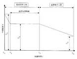
次に、実施の形態1の動作について図3を用いて説明する。図3は実施の形態1に係る炊飯器の内鍋の温度と経過時間の関係を示すタイムチャートの模式図である。
始めに、所定量の米と米量に適した水の入った内鍋3を内鍋収納部4へ収納し、蓋2により密閉する。次に、設定入力部5により、表示部6で確認しながら、好みの炊飯メニューを選択し、予約炊飯の場合は開始時間の設定を行い、炊飯の「実行」を選択することで炊飯が開始される。この時、炊飯中である旨を表示部6に表示し、また、計時部10は時間の計測を開始し、消費電力量計測部9は消費電力量の計測を開始する。なお、「実行」が選択される前に、設定入力部5によって温度保持工程における保持温度や温度保持時間が設定されたときは、その設定内容で温度保持工程が実施されるようになっている。設定入力部5で温度保持時間が設定された場合、その時間に対応する所定値が選択される。Next, the operation of the first embodiment will be described with reference to FIG. FIG. 3 is a schematic view of a time chart showing the relationship between the temperature of the inner pot of the rice cooker according to
First, an
「実行」が選択された際、予熱工程から開始する。炊飯開始時のまだ吸水が不十分である米を急に沸騰させてしまうと、米表面の糊化したデンプンにより、米内部への水の浸透が妨げられ、ご飯に芯が残りやすくなる。これを防止するために、予熱工程では、米に十分な水を浸透させる。精白米の含水率は、13%〜15%程度で、デンプンが糊化していない状態では、30%程度まで吸水する。また、吸水速度は、水温の高い方が速い。従って、予熱工程では、米表面のデンプンが糊化しない程度に高い温度で保持することにより、短い時間で米に十分な水を吸水させることができるようになる。図3の例では、内鍋3を所定温度TY(例えば、60℃)まで加熱した後、所定時間tY(例えば、15分)経過するまで、その温度を保持する。When “execute” is selected, a preheating process is started. If the rice, which still has insufficient water absorption at the start of rice cooking, is suddenly boiled, the gelatinized starch on the surface of the rice hinders the penetration of water into the interior of the rice, and the core tends to remain in the rice. In order to prevent this, in the preheating process, sufficient water is infiltrated into the rice. The water content of the polished rice is about 13% to 15%, and absorbs water up to about 30% when the starch is not gelatinized. Moreover, the higher the water temperature, the faster the water absorption speed. Therefore, in the preheating step, the rice can be absorbed with sufficient water in a short time by maintaining the temperature at such a high level that the starch on the rice surface is not gelatinized. In the example of FIG. 3, after heating the
次の沸騰工程では、予熱工程よりも大きな電力もしくは電力量により、予熱された米と水を一気に沸騰状態まで昇温させる。その後、沸騰状態を保持し、米と水の温度を均一にしながらデンプンの糊化を促進する。この時、米内部から水へ溶出してできるおねばは、糖等を含む甘味の多い成分であり、沸騰状態を保持することにより、米全体におねばが行き渡り、美味しいご飯に仕上げることができる。沸騰工程の終了付近では、米の糊化と蒸発により、余剰な水分が減少している。従って、内鍋3の温度は上昇を開始するが、ご飯の焦げや、必要以上の乾燥を防ぐため、内鍋3の温度が所定温度TF(110℃〜130℃程度)に達した時点で、沸騰工程を終了し、むらし工程へ移行する。In the next boiling step, the preheated rice and water are heated to a boiling state at a stretch with a larger electric power or electric power than in the preheating step. Then, the gelatinization of starch is promoted while maintaining the boiling state and keeping the temperature of rice and water uniform. At this time, rice balls that elute into the water from the inside of the rice are sweet ingredients that contain sugar, etc. By maintaining the boiling state, the rice balls spread throughout the rice and can be finished into delicious rice. . In the vicinity of the end of the boiling process, excess water is reduced due to gelatinization and evaporation of rice. Therefore, the temperature of the
むらし工程は、残った水分をご飯全体に均一に浸透させながら、芯を無くすための工程である。その際、加熱コイル7への通電(高周波電流)を一旦停止し、ご飯の乾燥や硬化を抑制するために、沸騰工程時よりも低い電力もしくは電力量で加熱されるように通電制御する。以上で炊飯工程が終了し、温度保持工程へ移行する。炊飯工程の終了時には、報知音等で炊飯終了を知らせると同時に、温度保持工程に移行した旨を表示部6に表示する。これまでの制御は、制御部15によって行われている。 The unevenness process is a process for eliminating the core while allowing the remaining moisture to uniformly penetrate the entire rice. At that time, the energization (high-frequency current) to the
一方、制御部15の調理情報演算部13は、炊飯工程が終了したかどうかを監視しており、炊飯工程の終了を確認したときに、加熱コイル7への通電を停止させるとともに、表示部6に温度保持工程に入った旨を表示させる。温度保持工程の開始時点においては、炊飯工程の終了直後のため、内鍋3の温度TOが高く、およそ90℃〜100℃程度である。従って、内鍋3の温度が保持温度TK、例えば40℃以上に低下するまでは、内鍋3内に結露が生じないように、断続的にむらし工程時よりも低い電力もしくは電力量で加熱されるように通電制御する。ここで、保持温度の下限値を40℃としたのは、一般的に、40℃で6時間程度の温度保持時間では、生菌数の増加が無いためである。On the other hand, the cooking
また、調理情報演算部13は、内鍋3の温度が保持温度TKまで低下したかどうかを判定するとともに、温度保持工程の開始から所定の経過時間範囲内において、逐次、経過時間に対する平均電力(消費電力量を経過時間で平均化した値)を算出し、この平均電力が調理情報記憶部14に格納された所定値に達しているかどうかを判定する。時間の経過と共に内鍋3の温度が保持温度TKに達したとき、内鍋3の温度が保持温度TKで保持されるように加熱コイル7を制御させる。そして、消費電力量を経過時間で平均化した平均電力が調理情報記憶部14に格納された所定値に達したときに、温度保持時間を経過したと判断して温度保持工程の終了判定を行う。In addition, the cooking
この時、制御部15は、温度保持工程の終了を報知音等で知らせると同時に、温度保持工程の表示を消灯する。なお、表示部6へは、温度保持工程の経過時間もしくは温度保持時間の残時間や、内鍋3の温度、消費電力量を表示するようにしても良い。これにより、使用者は、温度保持状態をより詳しく知ることが可能となる。 At this time, the
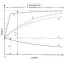
次に、温度保持工程における温度保持時間の設定について説明する。図4は温度保持工程における経過時間と消費電力量の関係を示す図である。この図に示す曲線は保持温度73℃の温度保持実験により得られた計測結果で、図中の(1)は経過時間と消費電力量を経過時間で平均化した値(以下、Pa)との関係(以下、Pa曲線)を表し、(2)は経過時間と消費電力量(以下、Ps)の関係(以下、Ps曲線)を表わす。 Next, setting of the temperature holding time in the temperature holding process will be described. FIG. 4 is a diagram showing the relationship between elapsed time and power consumption in the temperature holding step. The curve shown in this figure is a measurement result obtained by a temperature holding experiment at a holding temperature of 73 ° C., and (1) in the figure is the value obtained by averaging the elapsed time and the power consumption by the elapsed time (hereinafter referred to as Pa). A relationship (hereinafter referred to as Pa curve) is represented, and (2) represents a relationship between elapsed time and power consumption (hereinafter referred to as Ps) (hereinafter referred to as Ps curve).
なお、Paは、Psを経過時間で除算した値で、温度保持した時間に対する平均電力に相当する。また、所定時間△tにおけるPaの変化量△Pa(図示せず)は、図中の△Pa0、△Pa1に相当する値で、△Paが所定値以下もしくは一定の傾向を示す領域をVaと表わす。温度保持工程における経過時間と消費電力量の関係は、炊飯器固有の特性であり、対象となる炊飯器の保持温度や外気温度の違いによる消費電力量と経過時間との関係については、実験で求めたり、いくつかの基本的な実験で得られた結果から計算によって予測することが可能である。Note that Pa is a value obtained by dividing Ps by elapsed time, and corresponds to the average power with respect to the temperature holding time. Further, Pa change amount ΔPa (not shown) in a predetermined time Δt is a value corresponding to ΔPa0 , ΔPa1 in the figure, and ΔPa is a region where ΔPa is less than or equal to a predetermined value or has a constant tendency. Expressed as Va. The relationship between elapsed time and power consumption in the temperature holding process is a characteristic of rice cookers, and the relationship between power consumption and elapsed time due to differences in the holding temperature of the target rice cooker and outside air temperature is It is possible to obtain or predict by calculation from the results obtained in some basic experiments.
Ps曲線は、温度保持工程開始時の消費電力量の立ち上がりが若干遅くなる。これは、前述したように炊飯工程の終了直後の温度TOがTKよりも高いことから、加熱コイル7への電力供給が停止もしくは抑制されるためである。内鍋3の温度がTKに達した後は、温度保持制御を開始し、炊飯器からの放熱量と等しくなるように電力の供給を制御しながら温度保持を行うため、消費電力量は直線的に単調増加の傾向を示す。In the Ps curve, the rise in power consumption at the start of the temperature holding process is slightly delayed. This is because the power supply to the
一方、Pa曲線では、温度保持工程の開始時における△Paは非常に大きいが、時間が経過するに従い、徐々に小さくなる傾向を示す曲線に置き換えることが可能となる。ここで、Paを仮に電力消費速度と表現すると、Pa曲線は、温度保持工程の開始後、Va開始時点に到るまでの所定の経過時間範囲では、時間の経過とともに電力消費速度が速くなっていき、Va開始時点以降では、電力消費速度が速い状態を維持したまま、時間の経過とともに電力が消費されていく現象を表わしている。すなわち、Vaは、温度保持工程の開始時点からVa開始時点に到る所定の経過時間範囲に比べ、大きな電力が必要となる経過時間範囲であることを表わしている。 On the other hand, in the Pa curve, ΔPa at the start of the temperature holding step is very large, but it can be replaced with a curve that tends to gradually decrease with time. Here, if Pa is expressed as a power consumption rate, the Pa curve shows that the power consumption rate becomes faster with the passage of time in a predetermined elapsed time range from the start of the temperature holding process until reaching the Va start time point. After the Va start time, this represents a phenomenon in which power is consumed over time while maintaining a high power consumption speed. That is, Va represents an elapsed time range in which a larger amount of power is required than a predetermined elapsed time range from the start time of the temperature holding process to the Va start time.
以上のように、所定の温度保持時間を設定する際に、Pa曲線の特性から得られる経過時間と電力消費速度の関係を用いることで、電力消費速度が速くなる所定の経過時間範囲を明確にすることができるようになるため、消費電力量の抑制に効果の得られる温度保持時間の設定が可能となる。 As described above, when setting the predetermined temperature holding time, by using the relationship between the elapsed time obtained from the characteristics of the Pa curve and the power consumption rate, a predetermined elapsed time range in which the power consumption rate is increased is clarified. Therefore, it is possible to set a temperature holding time that is effective for suppressing power consumption.
また、温度保持時間を、Pa曲線から得られる温度保持工程の開始時点からVa開始時点に到る所定の経過時間範囲で設定することにより、電力消費速度が遅い経過時間範囲で温度保持ができるようになるため、温度保持工程における消費電力量の抑制が可能となる。 In addition, by setting the temperature holding time within a predetermined elapsed time range from the start time of the temperature holding process obtained from the Pa curve to the Va start time, the temperature can be held in the elapsed time range where the power consumption rate is slow. Therefore, it becomes possible to suppress the power consumption in the temperature holding process.
また、Pa曲線より、温度保持工程の開始時点からVa開始時点に到る所定の経過時間範囲で温度保持時間を設定する手法を用いることにより、その保持時間が必然的に短縮されるようになり、温度保持工程における消費電力量の抑制が可能となる。 In addition, by using a method of setting the temperature holding time within a predetermined elapsed time range from the start time of the temperature holding process to the Va start time from the Pa curve, the holding time is inevitably shortened. In addition, it is possible to suppress power consumption in the temperature holding process.
また、温度保持に際しては、調理情報演算部13が消費電力量計測部9と計時部13の計測による計測値を用いて、PsやPaの値を逐次演算できるように構成しているため、Pa曲線やPs曲線を用いた制御が可能となり、消費電力量に応じた温度保持工程の終了判定を行うことができるようになる。 In addition, when the temperature is maintained, the cooking
また、温度保持工程の開始時点からVa開始時点に到る所定の経過時間範囲に適合する所定値Paを調理情報記憶部14に格納しておき、温度保持工程の開始時に、消費電力量計測部9と計時部13による計測値を用いて平均電力(消費電力量を経過時間で平均化した値)を算出し、この平均電力が前記の所定値Paに到達した時点で温度保持工程を終了するように制御することで、温度保持工程における消費電力量の抑制が可能となる。前記の演算・判定は、調理情報演算部13によって行われる。 In addition, a predetermined value Pa that matches a predetermined elapsed time range from the start time of the temperature holding process to the Va start time is stored in the cooking
また、温度保持工程の開始時点からVa開始時点に到る所定の経過時間範囲に適合する△tに対する△Pa(図示せず、なお、図中の△Pa0、△Pa1に相当する)を所定値として調理情報記憶部14に格納しておき、温度保持工程の開始時に、消費電力量計測部9と計時部13による計測値から△tに対する△Pa(平均電力)を算出し、この値が前記の所定値に到達した時点で温度保持工程を終了するように制御することで、外気温度が変化した場合においても、適切な温度保持工程の終了判定ができ、温度保持工程における消費電力量の抑制が可能となる。Further, ΔPa (not shown, corresponding to ΔPa0 and ΔPa1 in the figure) with respect to Δt suitable for a predetermined elapsed time range from the start time of the temperature holding process to the Va start time. It is stored in the cooking
また、温度保持工程の開始時時点からVa開始時点に到る所定の経過時間範囲に適合し、その範囲の任意の2点における△tに対する△Paの比、例えば、△Pa1/△Pa0の値を所定値として調理情報記憶部14に格納しておき、温度保持工程の開始時に、逐次、消費電力量計測部9と計時部13による計測値から△tに対する△Paを算出し、かつ、その直前もしくはそれ以前の所定の経過時間に計測して算出した△tに対する△Paで除算し、この値が前記の所定値に達した時点で温度保持工程を終了するように制御することで、外気温度が変化した場合においても適切な温度保持工程の終了判定ができ、温度保持工程における消費電力量の抑制が可能となる。Further, it matches a predetermined elapsed time range from the start time of the temperature holding process to the Va start time, and the ratio of ΔPa to Δt at any two points in the range, for example, ΔPa1 / ΔPa0. Is stored in the cooking
また、△Paを用いた終了判定を行う場合は、温度保持工程の開始直後から所定時間の間もしくは内鍋3の温度が保持温度に到達するまでの経過時間、又は電力供給が停止あるいは抑制される経過時間範囲で温度保持工程の終了判定を行わないようにし、温度保持工程の初期時の△Paの変動を除外することで、温度保持工程の終了時の△Paの値との混同を避けることが可能となり、温度保持工程の早切れを防止することができる。 Moreover, when performing completion | finish determination using (DELTA) Pa, it is the elapsed time until the temperature of the
また、温度保持工程の開始時点からVa開始時点に到る所定の経過時間範囲に適合するPaと、これに対応する経過時間を乗算することで得られるPsを所定値として調理情報記憶部14に格納しておき、温度保持工程の開始時に、消費電力量計測部9による計測値が前記の所定値Psに到達した時点で温度保持工程を終了するように制御することで、温度保持工程における消費電力量の抑制が可能となる。 In addition, in the cooking
また、表示部6は、設定入力部5で設定される設定内容を表示するようにしているので、温度保持工程の開始時点からVa開始時点に到る所定の経過時間範囲の上限時間を標準の温度保持時間として調理情報記憶部14に格納しておき、使用者によって温度保持時間が設定された際には、上限の温度保持時間を表示させることで、使用者は、消費電力量の抑制に効果のある温度保持時間の上限時間を知ることが可能となり、この範囲で温度保持時間を設定することで消費電力量の抑制が可能となる。 Further, since the
また、上限の温度保持時間を表示部6に表示する際には、炊飯量に対応した温度保持時間を表示し、使用者が上限の温度保持時間内で温度保持時間を設定できるようにすることで、炊飯量検知部等を備えない場合においても、消費電力量の抑制に効果のある温度保持時間の設定が可能となる。 Moreover, when displaying the upper limit temperature holding time on the
また、使用者により温度保持工程における保持温度を設定入力部5により40℃以上の範囲で調整できるようにしているため、保持温度に対応した上限の温度保持時間を表示し、使用者が上限の温度保持時間内で温度保持時間を設定できるようにすることで、使用者の好みにあった温度のご飯を利用することができ、消費電力量の抑制に効果のある温度保持時間の設定が可能となる。 Further, since the user can adjust the holding temperature in the temperature holding process within the range of 40 ° C. or more by the setting
次に、前記の温度保持工程における所定の経過時間設定手法を用いると同時に、ご飯の保持状態から温度保持工程における所定の経過時間を設定する場合について、図4、図5を用いて説明する。図5は実施の形態1に係る炊飯器の温度保持工程におけるご飯の色と経過時間の関係を示す図である。図中の(1)Lnは、感知しえる程度に色が変化した場合の色差の目安である。
ご飯表面の色の変化は、温度保持時間が長くなるに従い大きくなり、色差は、およそ6時間程度(図示せず)でLnまで変化する。この時、ご飯の含水率は、炊飯直後に比べると2%程度低下するが、12時間温度保持した場合は、5%以上低下してしまう(図示せず)。また、図4に示すPa曲線より、Vaは6時間程度から開始しており、これ以上の範囲では、電力量消費速度が大きくなり、時間経過に伴い多大な電力量を消費する。従って、温度保持工程における温度保持時間の上限値を6時間もしくはそれ以内に設定することで、温度保持工程における消費電力量の抑制が可能となる。Next, the case where the predetermined elapsed time setting method in the temperature holding step is used and the predetermined elapsed time in the temperature holding step is set from the rice holding state will be described with reference to FIGS. 4 and 5. FIG. 5 is a diagram showing the relationship between the color of rice and the elapsed time in the temperature maintaining step of the rice cooker according to the first embodiment. (1) Ln in the figure is a measure of the color difference when the color changes to a perceivable level.
The change in the color of the rice surface increases as the temperature holding time becomes longer, and the color difference changes to Ln in about 6 hours (not shown). At this time, the moisture content of the rice is reduced by about 2% as compared to immediately after cooking, but when the temperature is maintained for 12 hours, it is reduced by 5% or more (not shown). Further, from the Pa curve shown in FIG. 4, Va starts from about 6 hours, and in a range beyond this, the power consumption speed increases, and a great amount of power is consumed over time. Therefore, by setting the upper limit value of the temperature holding time in the temperature holding process to 6 hours or less, it is possible to suppress the power consumption in the temperature holding process.
また、温度保持工程における温度保持時間の上限値を6時間もしくはそれ以内に設定することで、ご飯の見た目の変化や乾燥による食味の低下と、菌の繁殖を抑制した温度保持が可能となる。 In addition, by setting the upper limit value of the temperature holding time in the temperature holding step to 6 hours or less, it is possible to maintain the temperature while suppressing the appearance change of rice and the taste caused by drying, and the propagation of bacteria.
また、温度保持工程における温度保持時間の上限を6時間以内とし、予め調理情報記憶部5にこれ以上の温度保持制御をしない設定としておくことで、外気温度等の影響により温度保持工程の終了判定が難しい場合であっても、不必要な温度保持を防止できるため、温度保持工程における消費電力量を確実に抑制することが可能となる。 In addition, the upper limit of the temperature holding time in the temperature holding process is set to 6 hours or less, and the cooking
実施の形態2.
以上の実施の形態1では、温度保持工程において、Pa(消費電力量を経過時間で平均化した値)を用いて温度保持時間を設定することで、消費電力量の抑制に効果の得られる温度保持時間の範囲を明確にしたものであるが、実施の形態2は、温度保持工程の後に、ご飯の保管を行うための温度降下工程を設けたものであ。なお、実施の形態2の炊飯器の構成については、図1および図2を用いて説明し、温度保持工程終了までの動作については、実施の形態1と同じであるため省略する。
In the first embodiment described above, in the temperature holding step, the temperature at which the effect of suppressing the power consumption can be obtained by setting the temperature holding time using Pa (a value obtained by averaging the power consumption by the elapsed time). Although the holding time range is clarified, the second embodiment is provided with a temperature lowering step for storing rice after the temperature holding step. In addition, about the structure of the rice cooker of
実施の形態2においては、制御部15に、温度保持工程の終了後に温度降下工程を実施する調理情報演算部13が設けられ、設定入力部5には、後述する降下温度TD以上の温度値を設定可能なスイッチ(図示せず)が設けられている。降下温度TDは、例えば40℃で、調理情報記憶部14にデータとして格納されている。また、温度降下工程には、6時間を上限とする時間が設定され、前記の調理情報記憶部14にデータとして格納されている。上限の6時間は、外気温度が高く内鍋3の温度が降下温度TDまで低下しないときの温度降下工程の上限時間である。降下温度TDの40℃、温度降下工程の6時間は、ご飯に生菌数の増加が無く、安全に保管するためである。設定入力部5の設定による降下温度TDの値は40℃以上の温度である。In the second embodiment, the
調理情報演算部13は、温度降下工程に入ると、内鍋温度検知部11により検知された内鍋3の温度が降下温度TDまで低下したかどうかを判定し、内鍋3の温度が降下温度TDに達したときに温度降下工程の終了判定を行い、また、温度降下工程の開始から読み込んだ計時部1の経過時間が6時間を達したかどうかを判定し、内鍋3の温度が降下温度TDに達する前に6時間を経過したときは温度降下工程の終了判定を行う。また、温度降下工程の間、内鍋温度検知部11により検知される内鍋3の温度を表示部6に表示している。
次に、温度降下工程時の動作について図6を参照しながら説明する。図6は実施の形態2に係る炊飯器の温度降下工程における内鍋の温度と経過時間の関係を示すタイムチャートの模式図である。
制御部15は、調理情報演算部13によって温度保持工程の終了判定が行われると、まず、加熱コイル7への通電(高周波電流)を停止し、報知音等(図示せず)で温度保持工程の終了を知らせると同時に、温度降下工程に入った旨を表示部6に表示する。一方、制御部15の調理情報演算部13は、消費電力量計測部9と計時部10とによる計測結果を調理情報記憶部14に格納し、内鍋温度検知部11の検知による内鍋3の温度を読み込んで表示部6に表示する。なお、温度降下工程の経過時間や消費電力量(又は消費電力)を表示部6に表示するようにしてもよい。Next, the operation during the temperature lowering process will be described with reference to FIG. FIG. 6 is a schematic diagram of a time chart showing the relationship between the temperature of the inner pot and the elapsed time in the temperature lowering process of the rice cooker according to the second embodiment.
When the end of the temperature holding process is determined by the cooking
次いで、内鍋3の温度が降下温度TDまで低下したかどうかを判定し、内鍋3の温度が降下温度TDに達していないときは、温度保持工程の開始から6時間が経過したかどうかを判定する。図6に示すように内鍋3の温度が時間の経過とともに低下し、降下温度TDまで低下したときに温度降下工程の終了と判定する。また、外気温度が高く内鍋3の温度が降下温度TDまで低下する前に6時間を経過したときは、前記と同様に温度保持工程の終了と判定する。この時、制御部15は、報知音等で温度降下工程の終了を知らせると同時に、温度降下工程の動作中である旨の表示を消灯する。その際、内鍋3の温度や消費電力量(又は消費電力)を継続して表示部6に表示するようにしてもよい。Then, it is determined whether the temperature of the
また、温度降下工程に入った際に、設定入力部5により、下限値の40℃以上の降下温度が設定されてた場合には、その温度を降下温度TDとし、内鍋3の温度がその値まで低下したときに温度降下工程の終了と判定する。なお、設定入力部5による降下温度の設定は、炊飯開始時や炊飯工程の終了以降の任意の時点で可能とする。Moreover, when the temperature drop process is set, when the drop temperature of the lower limit value of 40 ° C. or more is set by the setting
以上のように実施の形態2によれば、温度保持工程の後に温度降下工程を設け、この温度降下工程に入った際に加熱コイル7を停止するようにしたので、消費電力量(又は消費電力)を抑制しながらご飯の保管時間を延長することが可能となる。また、温度降下工程では、通常の保持温度に比べ低い温度でご飯を保管しているため、ご飯の乾燥や変色による食味の低下を抑制しながら、保管時間を延長することが可能となる。 As described above, according to the second embodiment, since the temperature lowering step is provided after the temperature holding step and the
また、温度降下工程の降下温度の下限値を生菌が増加しない40℃以上に設定するようにしているので、ご飯を安全に保管することが可能となる。さらに、温度降下工程の上限時間を生菌が増加しない6時間に設定しているので、外気温度が高い等で内鍋3の温度降下の時間が著しく長くなってしまう恐れのある場合においても、ご飯を安全に保管することが可能となる。 Moreover, since the lower limit value of the temperature drop in the temperature drop step is set to 40 ° C. or more at which viable bacteria do not increase, rice can be stored safely. Furthermore, since the upper limit time of the temperature drop process is set to 6 hours in which viable bacteria do not increase, even when the temperature drop time of the
また、温度降下工程の間、内鍋3の温度を表示部6に表示するようにしているので、使用者が温度降下状態を詳しく知ることができるようになり、温度降下途中の所望の温度でご飯を利用することが可能となる。また、設定入力部5により、予め設定された降下温度TD以上の温度を設定できるようにしたので、好みにあった温度のご飯を利用することが可能となる。Moreover, since the temperature of the
なお、実施の形態2では、温度降下工程を温度保持工程の後に実施するようにしたが、炊飯工程の終了直後に温度降下工程を実施するようにしても良い。
また、温度降下工程の時間を6時間としたが、温度保持工程の開始からの経過時間も含めて6時間としても良いし、また、温度保持工程で内鍋3の温度が保持温度に達したときからの経過時間も含んで6時間としても良い。この場合においても生菌の増加を抑制でき、安全なご飯を提供できる。In the second embodiment, the temperature lowering step is performed after the temperature holding step, but the temperature lowering step may be performed immediately after the end of the rice cooking step.
Moreover, although the time of the temperature fall process was 6 hours, it is good also as 6 hours including the elapsed time from the start of a temperature holding process, and the temperature of the
また、温度降下工程の上限時間を6時間としたが、設定入力部5により、温度降下工程の時間を6時間以内で設定できるようにしても良い。その場合、時間の設定を炊飯開始時や炊飯工程の終了以降の任意の時点で可能とする。 Further, although the upper limit time of the temperature lowering process is 6 hours, the setting
また、温度降下工程の終了判定を、内鍋3の温度が降下温度TDまで低下したとき、又は経過時間が6時間に達したときに行うようにしたが、6時間経過するまで温度降下工程を実施するようにしても良い。その場合、内鍋3の温度が40℃で保たれるように、加熱コイル7を制御する。この場合、温度保持工程時に消費された電力量より低い電力量になるようにする。なお、消費電力量に代えて、温度保持工程時に消費された電力(又は電力量)より低い電力で加熱コイル7を制御するようにしても良い。Further, the end determination temperature drop step, when the temperature of the
また、設定入力部5に「おにぎり」モードや「お弁当」モードを選択できるスイッチ(図示せず)を設け、何れか一方が操作されたときに、例えば40℃の降下温度TDが設定されるようにしても良い。その40℃はやけどや結露のしにくい温度で、「おにぎり」モードにより温度降下工程が終了した場合には、ご飯を安全に握ることができる。また、「お弁当」モードにより温度降下工程が終了したときに、ご飯をお弁当箱に詰めても、お弁当箱内での結露が殆ど無く、食べる時に水っぽくならないようにすることが可能となる。Also, a switch (not shown) that can be selected to "onigiri" mode and "lunch" mode setting
また、温度保持工程の保持温度が40℃〜60℃の範囲で設定された場合は、温度保持工程後に温度降下工程を行わないようにしても良い。この場合も生菌の増加を抑制でき、安全なご飯を提供できる。 Moreover, when the holding temperature of a temperature holding process is set in the range of 40 to 60 degreeC, you may make it not perform a temperature fall process after a temperature holding process. Also in this case, the increase of viable bacteria can be suppressed and safe rice can be provided.
また、設定入力部5に温度保持工程と温度降下工程で構成される「長時間温度保持」モードを選択できるスイッチ(図示せず)を設け、そのスイッチが操作された場合には、消費電力量を抑制しながら、ご飯の保管時間を長くすることが可能となる。 Further, the setting
実施の形態3.
前述した実施の形態2では、温度保持工程の終了後に温度降下工程を実施して、食味の低下や消費電力量を抑制しながらご飯の保管時間を延長できるようにしたものであるが、実施の形態3は、温度降下工程の後に再温度保持工程を設けたものである。この工程は、温度降下工程が終了したにもかかわらず、ご飯を保管していることを忘れてそのまま放置してしまった場合や、もう少し食品保管時間を延長したい場合に設定される。なお、実施の形態3の炊飯器の構成については、図1および図2を用いて説明し、温度降下工程終了までの動作については、実施の形態1、2と同じであるため省略する。
In the second embodiment described above, the temperature lowering step is performed after the temperature holding step is completed, and the storage time of the rice can be extended while suppressing the decrease in the taste and the power consumption. In the third mode, a re-temperature holding step is provided after the temperature lowering step. This process is set when the user has forgotten that the rice has been stored and left it as it is despite the completion of the temperature lowering process, or when the food storage time is to be extended a little. In addition, about the structure of the rice cooker of
実施の形態3においては、設定入力部5に、温度降下工程の終了後に再温度保持工程を実施させるスイッチ(図示せず)が設けられ、制御部15には、温度降下工程の終了後に内鍋3の温度をTK’まで昇温して保持する再温度保持工程を備えた調理情報演算部13が設けられている。再温度保持工程の保持時間は、炊飯工程の温度保持制御に入ってからの6時間を上限とする時間で、保持温度TK’とともに調理情報記憶部14にデータとして格納されている。前記の設定入力部5による再温度保持工程の設定は、炊飯開始時や、炊飯工程の終了時以降の任意の時点で可能になっている。なお、保持時間と保持温度TK’は、設定入力部5により、表示部6で確認しながら設定できるようにしても良い。In the third embodiment, the setting
調理情報演算部13は、再温度保持工程に入ると、加熱コイル7に通電させ、内鍋温度検知部11により検知された内鍋3の温度が保持温度TK’まで達したかどうかを判定し、内鍋3の温度が保持温度TK’に達したときに温度保持の制御を開始する。そして、その制御は計時部10の経過時間が保持時間に達したときに再温度保持工程を終了する。加熱コイル7による内鍋3の加熱は、内鍋3の温度がTK’よりも低い所定温度に到達した時点で、昇温時に比べて低い電力量(又は電力)で制御する。これは、保持温度TK’に対するオーバシュートを防止するためである。When the cooking
次に、再温度保持工程時の動作について図7を参照しながら説明する。図7は実施の形態3に係る炊飯器の再温度保持工程における内鍋の温度と経過時間の関係を示すタイムチャートの模式図である。
制御部15は、調理情報演算部13によって温度降下工程の終了判定が行われると、まず、加熱コイル7への通電(高周波電流)を開始し、所定の電力量で内鍋3が加熱されるようにするとともに、報知音等(図示せず)で温度降下工程の終了を知らせ、かつ、再温度保持工程に入った旨を表示部6に表示する。一方、制御部15の調理情報演算部13は、消費電力量計測部9と計時部10とによる計測結果を調理情報記憶部14に格納し、記憶内鍋温度検知部11の検知による内鍋3の温度を読み込んで表示部6に表示する。なお、再温度保持工程の経過時間や消費電力量を表示部6に表示するようにしてもよい。Next, the operation during the re-temperature holding step will be described with reference to FIG. FIG. 7: is a schematic diagram of the time chart which shows the relationship between the temperature of an inner pot in the re-temperature holding process of the rice cooker which concerns on
When the end of the temperature drop process is determined by the cooking
次いで、内鍋3の温度が保持温度TK’より低い所定温度まで昇温したかどうかを判定し、内鍋3の温度が所定温度に達していないときは、内鍋3の温度の監視を継続する。この動作を繰り返し行っている内に、内鍋3の温度が所定温度に達すると、制御部15は、内鍋3の温度が保持温度TK’で保たれるように、昇温時の電力量と比べて低い電力量で加熱する。一方、調理情報演算部13は、保持時間を経過したかどうかを判定し、保持時間を経過したときに再温度保持工程の終了と判定する。この時、制御部15は、報知音等で再温度保持工程の終了を知らせると同時に、再温度保持工程の動作中である旨の表示を消灯する。その際、内鍋3の温度や消費電力量を継続して表示部6に表示するようにしてもよい。Next, it is determined whether the temperature of the
ここで、内鍋3の昇温時の加熱コイル7の電力量について図8を用いて説明する。図8は再温度保持工程における電力量の供給の違いによる内鍋3の温度の上昇特性を示す図である。これは、実験により得られた値を基に計算した結果である。
図中の(1)はむらし工程以上の電力量より加熱した場合を、(2)は温度保持工程の終了時に消費電力量計測部9によって調理情報記憶部14に格納された電力量で加熱した場合を、(3)は(2)と同様、温度保持工程の終了時に消費電力量計測部9と計時部10の計測値から得られた平均電力量Paにより加熱した場合を、(4)は温度降下工程の終了後も40℃で温度保持した場合の内鍋3の温度上昇特性で、温度保持工程を73℃で温度保持し、温度降下工程を40℃で終了させた後、引き続き40℃で再温度保持した場合を表わす。(5)は、参考として温度降下工程の終了後は加熱せずそのまま放置した場合の内鍋3の温度変化を表わしている。Here, the electric energy of the
In the figure, (1) is the case where the heating is performed with the electric energy equal to or higher than the unevenness process, and (2) is the heating with the electric energy stored in the cooking
まず、(1)による加熱は、短時間でご飯の温度を保持温度TK’まで昇温させることが可能となる。これにより、生菌の増加が抑制され、保管時間が長くなった場合でも安全なご飯の提供が可能となる。しかし、加熱コイル7の電力量が大きいため、ご飯表面の水分が蒸発しやすく、特に、内鍋3内のご飯と内鍋3の内壁部の接触部においては、乾燥により硬くなったり、黄変の原因となる場合がある。また、内鍋3内に残っているご飯の量が少ない場合は、ご飯自体の熱容量が小さいため、ご飯に対する加熱量が過剰になりやすく、ご飯の食味が低下しやすい。従って、残り少なくなったご飯をすぐにあつあつの状態で利用したい場合に行うようにすることで、昇温後にご飯を保管する時間を短くでき、食味の低下を抑制したおいしいご飯を提供できる。First, the heating according to (1) makes it possible to raise the temperature of the rice to the holding temperature TK ′ in a short time. Thereby, the increase in viable bacteria is suppressed, and even when the storage time is prolonged, it is possible to provide safe rice. However, since the amount of electric power of the
また、(2)(3)による加熱は、加熱コイル7の電力量が(1)に比べて必然的に小さいため、ご飯は保持温度TK’までゆっくりと加熱されるようになる。これにより、内鍋3に残っているご飯の量が少ない場合でも、ご飯の熱容量に対して加熱量が過剰になることがないため、経過時間に対するご飯表面の水分蒸発量が減少し、乾燥による硬化や、黄変が抑制され、食味の低下を防止しながらご飯の保管時間を延長することが可能となる。また、(2)(3)では、加熱コイル7の電力量を抑制しながら、ご飯をゆっくりと昇温させるようにしているため、食品保管時の消費電力量の抑制が可能となる。In addition, since the heating by (2) and (3) is inevitably smaller than that in (1), the rice is slowly heated to the holding temperature TK ′. Thereby, even when there is little quantity of the rice which remains in the
また、(4)による加熱は、再温度保持工程の時間を6時間以下に設定することにより、生菌の増加を抑制し、安全なご飯を提供できるようになる。ここで、温度保持工程や温度降下工程において、使用者が設定入力部5で保持温度を40℃〜60℃で設定を行った場合は、計時部10により、炊飯後、内鍋3の温度が保持温度に到達してからの計測時間が6時間以下になるように制御することで、生菌の増加を抑制した安全なご飯を提供することでき、低温で温度保持することから、ご飯の乾燥や黄変を防止し、食味の低下も抑制可能となる。また、低温で温度保持することにより、加熱コイル7の電力量が(1)から(3)に比べて小さくなるため、食品保管時の消費電力量を抑制することができる。 Moreover, the heating by (4) can suppress the increase in a living microbe and can provide safe rice by setting the time of a re-temperature holding process to 6 hours or less. Here, in the temperature holding step and the temperature lowering step, when the user sets the holding temperature at 40 ° C. to 60 ° C. with the setting
また、温度保持工程、温度降下工程および再温度保持工程で構成される食品保管制御を「長時間温度保持」モードとして、予め設定しておくことで、使用者が設定入力部5により「長時間温度保持」モードを選択した場合においても、消費電力量を抑制しながら、ご飯の保管時間を長くすることが可能となる。 In addition, the food storage control configured by the temperature holding process, the temperature lowering process, and the re-temperature holding process is set in advance as a “long-time temperature holding” mode, so that the user can set “long-time temperature” by the setting
また、再温度保持工程において、温度保持によりご飯の乾燥や臭いが気になるような場合には、再温度保持工程の終了後に、沸騰工程以下の電力量で加熱されるように加熱コイル7を制御し、内鍋3の温度を103℃以上で所定時間加熱しながら、アミノカルボニル反応の一種であるメイラード反応を促進させる、例えば「おこげ」モードを設定入力部5により選択可能とし、ご飯の臭いが気にならない、香ばしい香りのする美味しいご飯に仕上げることで、温度保持したご飯の食味を改善することができるようになる。また、「おこげ」モードは、炊飯工程の終了後や、温度保持工程の終了後、また、温度降下工程の終了後に行ってもよい。 Further, in the re-temperature holding step, if the drying or smell of the rice is worrisome due to the temperature holding, the
また、再温度保持工程は、温度降下工程中に表示部6に表示される内鍋3の温度よりも高い温度にしたい場合や、使用者が設定入力部5により設定された保持温度よりも高い温度で再設定したい場合において実行してもよく、調理情報記憶部14に標準設定として、所定の電力量を予め調理情報記憶部14に保持するようにしているので、(2)(3)の加熱を用いることで、食味を低下させること無く、消費電力量を抑制しながら、ご飯の温度を上昇させることが可能となる。 Further, the re-temperature holding step is higher than the holding temperature set by the setting
実施の形態4.
本実施の形態は、前述した実施の形態1、2、3において、環境条件の変化に適応したご飯保管時における時間設定の補正や、ご飯の加熱時における加熱量を補正できるようにしたものである。
図9は実施の形態4に係る炊飯器の構造を示す断面図、図10は実施の形態4に係る炊飯器の回路構成を示すブロック図である。なお、図1および図2で説明した実施の形態1と同一又は相当部分には同じ符号を付し説明を省略する。
In this embodiment, in the first, second, and third embodiments described above, it is possible to correct the time setting at the time of storing rice adapted to the change of the environmental conditions and the heating amount at the time of heating the rice. is there.
FIG. 9 is a sectional view showing the structure of the rice cooker according to the fourth embodiment, and FIG. 10 is a block diagram showing the circuit configuration of the rice cooker according to the fourth embodiment. In addition, the same code | symbol is attached | subjected to the part which is the same as that of
実施の形態4の炊飯器は、本体ケース1の底部に外気温度検知部12が設置されている。この外気温度検知部12の検知による外気温度は、ご飯保管時における保管時間の補正や、ご飯の加熱時における加熱量の補正に使用するための情報である。なお、本実施の形態では、電子部品温度検出部(図示せず)と併用することにより外気温度を検知する構成としているが、これに限定されるものではなく、外気温度に相当する温度を検知できれば良い。 In the rice cooker of the fourth embodiment, an outside air
次に、外気温度検知部12を用いた場合の動作について説明する。
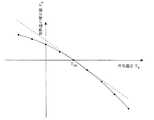
まず、温度保持工程における温度保持時間の補正について図11を用いて説明する。図11は標準外気温度Ts(例えば20℃)に対して実施の形態1で得られた温度保持時間を基準(補正値=0)とした時の外気温度TRと温度保持時間の補正値SKの関係を表したものである。図中の黒丸は、温度保持実験結果を用いて算出したTRとSKの関係を表わす点で、線は数式を用いた近似曲線である。なお、TRと温度保持時間の関係は、炊飯器固有の特性であり、実験で求めたり、いくつかの基本的な実験で得られた結果から計算によって予測することが可能である。
図11より、SKは、TRに対して直線的な変化ではなく曲線的に変化し、3次曲線と相関の強い結果となっている。そのため、外気温度検知部12で検知されたTRを用いて図11の点線で示すように直線的な温度保持時間の補正を行うと、例えば、TRが高い場合では、温度保持時間が長くなってしまい、温度保持における消費電力量の抑制効果が低下する。Next, the operation when the outside air
First, correction of the temperature holding time in the temperature holding step will be described with reference to FIG. FIG. 11 shows the outside air temperature TR and the temperature holding time correction value S when the temperature holding time obtained in the first embodiment is used as a reference (correction value = 0) with respect to the standard outside air temperature Ts (for example, 20 ° C.).This shows the relationship ofK. The filled in circles, in that the representative of the relationship between TR and SK calculated by using the temperature holding test results, the line is an approximation curve using the formula. The relationship between TR and the temperature holding time is cooker specific characteristics can be predicted by calculation from the results obtained in or determined experimentally, some basic experiments.
From FIG. 11, SK varies curvedly rather than a linear change with respect to TR, which is a strong result correlation with cubic curve. Therefore, when the outside air
従って、外気温度検知部12で検知された外気温度から調理情報演算部13により算出された、温度保持時間の補正値を用いることで、使用者が設定入力部5により温度保持時間を設定する際には、正確な温度保持時間の上限値を示すことができるため、使用者は示された温度保持時間の範囲内において、消費電力量の抑制を意識しながら、温度保持時間を安心して設定することが可能となる。 Therefore, when the user sets the temperature holding time by the setting
また、TRとSKの関係を予め調理情報記憶部14へ格納しておくことで、使用者が設定入力部5により温度保持時間を設定する際には、外気温度検知部12で検知された外気温度TRから正確な温度保持時間を調理情報記憶部14から読み出せばよく、使用者は示された温度保持時間の上限値の範囲内において、消費電力量の抑制を意識しながら、温度保持時間を安心して設定することが可能となる。Further, by storing the relationship between TR and SK previously to the cooking
次に、温度降下工程の時間の補正について図12を用いて説明する。図12は標準外気温度Ts(例えば20℃)において降下温度TD(例えば40℃)まで内鍋3の温度が降下するのに要する時間(以下、温度降下時間)を基準(補正値=0)とした時の外気温度TRと温度降下時間の補正値SDの関係を表したものである。図中の黒丸は、温度降下実験結果を用いて算出したTRとSDの関係を表わす点で、線は数式を用いた近似曲線である。なお、TRと温度降下時間の関係は、炊飯器固有の特性であり、実験で求めたり、いくつかの基本的な実験で得られた結果から計算によって予測することが可能である。
図12より、SDは、TRに対して直線的な変化ではなく曲線的に変化し、本実施の形態では2次曲線と相関の強い結果となっている。そのため、外気温度検知部12で検知されたTRを用いて図12の点線で示すように直線的な温度降下時間の補正を行うと、例えば、TRが高い場合では、温度降下時間が短く予測されるため、予測時間が経過した後も、ご飯の温度が高い状態となる。これにより、使用者は設定した温度へ降下するまで、さらに、待たなければならなくなる。Next, correction of the time of the temperature drop process will be described with reference to FIG. FIG. 12 is based on the time required for the temperature of the
From FIG. 12, SD changes not in a linear manner but in a curve with respect to TR , and in this embodiment, the result has a strong correlation with the quadratic curve. Therefore, when the outside air temperature detection unit corrected linear temperature drop time as shown using the sensed TR by the dotted line in FIG. 12 at 12, for example, in the case TR is high, short temperature drop time Since it is predicted, the temperature of the rice is high even after the prediction time has elapsed. As a result, the user has to wait further until the temperature falls to the set temperature.
従って、外気温度検知部12で検知されたTRから調理情報演算部13により算出された、SDを用いることで、使用者が設定入力部5により降下温度を設定する際には、正確な温度降下時間を示すことができるため、使用者は所望の温度のご飯を得るために予測された温度降下時間以上に待たされたり、また、気づいた時には温度降下工程が終了しており、ご飯が冷めてしまっている等の心配をすることなく、安心して使用することが可能となる。Therefore, it calculated by the
また、TRとSDの関係を予め調理情報記憶部14へ格納しておくことで、使用者が設定入力部5により降下温度を設定する際には、外気温度検知部12で検知されたTRから正確な温度降下時間を調理情報記憶部14から読み出せばよく、使用者は所望の温度のご飯を得るために予測された温度降下時間以上に待たされたり、また、気づいた時には温度降下工程が終了しており、ご飯が冷めてしまっている等の心配をすることなく、安心して使用することが可能となる。Further, by storing the relationship between TR and SD advance to the cooking
次に、再温度保持工程における加熱量の補正について図13を用いて説明する。図13は実施の形態3の図8で説明した(2)、(3)加熱制御を用いた場合に、温度保持工程の終了時の外気温度TRK(例えば20℃)とPsもしくはPaに対し、再温度保持工程の開始時の外気温度がTRへ変化した時のTRと電力もしくは電力量に相当する加熱量の補正値PKの関係を表わしたものである。図中の黒丸は温度保持実験結果を用いて算出したTRとPKの関係を表わす点で、線は数式を用いた近似曲線である。なお、TRと加熱量の関係は、炊飯器固有の特性であり、実験で求めたり、いくつかの基本的な実験で得られた結果から計算によって予測することが可能である。
図13より、PKはTRに対して直線的な変化ではなく曲線的に変化し、本実施の形態では2次曲線と相関の強い結果となっている。そのため、外気温度検知部12で検知されたTRを用いて図13の点線で示すように直線的な加熱量の補正を行うと、加熱量が大きくなるため、再温度保持工程における消費電力量の抑制効果が低下する。Next, correction of the heating amount in the re-temperature holding step will be described with reference to FIG. FIG. 13 shows the case (2) and (3) withrespect to the outside air temperature TRK (for example, 20 ° C.) at the end of the temperature holding process and Ps or Pa when using the heating control described in FIG. The relationship between TR when the outside air temperature at the start of the re-temperature holding process is changed to TR and the correction value PK of the heating amount corresponding to the electric power or the electric energy is shown. The black circles in the figure represent the relationship between TR and PK calculated using the temperature holding experiment results, and the lines are approximate curves using mathematical expressions. The relationship TR and the heating amount is a rice cooker specific characteristics can be predicted by calculation from the results obtained in or determined experimentally, some basic experiments.
From FIG. 13, PK changes not as a linear change but as a curve with respect to TR , and in this embodiment, the result has a strong correlation with the quadratic curve. Therefore, when correcting the linear heating amount as indicated by a dotted line in FIG. 13 by using the TR, which is detected by the outside air
従って、外気温度検知部12で検知されたTRから調理情報演算部13により算出されたPKを用いた加熱量の補正を行うことで、実施の形態3の図8の(2)、(3)に示す加熱制御を用いた場合においても、適正な加熱量で加熱することで再温度保持工程における過分な電力もしくは電力量の消費を避け、再温度保持工程における消費電力量の抑制が可能となる。Therefore, by performing the heating amount of correction using PK calculated by the
また、TRとPKの関係を予め調理情報記憶部14へ格納しておくことで、実施の形態3の図8の(2)、(3)に示す加熱制御を用いた場合においても、外気温度検知部12で検知されTRから適正な加熱量を調理情報記憶部14から読み出せばよく、これにより、再温度保持工程における過分な電力もしくは電力量の消費を避けることができるため、再温度保持工程における消費電力量の抑制が可能となる。Further, by storing the relationship between TR and PK in advance to the cooking
本発明を利用した加熱調理器を用いて食品の温度保持をすることにより、消費電力量の抑制に効果の得られる温度保持時間の範囲を明確にできるため、使用者が消費電力量の削減を意識しながらも安心して使用することができるようになる。また、消費電力量を抑制しながら、食品を安全に長時間保管出来るようになる。 By holding the temperature of the food using the heating cooker using the present invention, the range of the temperature holding time that is effective in suppressing the power consumption can be clarified, so the user can reduce the power consumption. You will be able to use it with confidence while being conscious. In addition, food can be safely stored for a long time while suppressing power consumption.
1 本体ケース、2 蓋、3 内鍋、4 内鍋収納部、5 設定入力部、6 表示部、
7 加熱コイル、8 電源回路、9 消費電力量計測部、10 計時部、11 内鍋温度検知部、12 外気温度検知部、13 調理情報演算部、14 調理情報記憶部、
15 制御部。1 body case, 2 lid, 3 inner pot, 4 inner pot storage section, 5 setting input section, 6 display section,
7 heating coil, 8 power supply circuit, 9 power consumption measuring unit, 10 timing unit, 11 inner pot temperature detecting unit, 12 outside air temperature detecting unit, 13 cooking information calculating unit, 14 cooking information storing unit,
15 Control unit.
Claims (32)
Translated fromJapanese本体ケースに開閉自在に係止され前記内鍋を覆う蓋と、
前記内鍋を加熱する加熱手段と、
前記内鍋の温度を検知する内鍋温度検知手段と、
前記加熱手段を制御する制御手段と、
消費電力や消費電力量を計測する計測手段と、
加熱調理の経過時間を計時する計時手段と、
加熱調理終了後に前記内鍋の温度を所定温度に保持する温度保持工程に入ったとき、前記計測手段により計測された消費電力量を前記計時手段により計時された温度保持工程における経過時間で平均化し、この平均化した値を用いて温度保持工程の温度保持時間を設定する調理情報演算手段と
を備えたことを特徴とする加熱調理器。An inner pot for cooking the food stored in the body case detachably,
A lid that is locked to the body case so as to be freely opened and closed and covers the inner pot;
Heating means for heating the inner pot;
An inner pot temperature detecting means for detecting the temperature of the inner pot;
Control means for controlling the heating means;
Measuring means for measuring power consumption and power consumption,
A time measuring means for measuring the elapsed time of cooking,
When the temperature holding step of holding the temperature of the inner pot at a predetermined temperature is entered after cooking, the power consumption measured by the measuring means is averaged with the elapsed time in the temperature holding step timed by the time measuring means. A cooking device comprising cooking information calculation means for setting the temperature holding time of the temperature holding step using the averaged value.
前記調理情報演算手段は、前記外気温度検知手段により検知された外気温度に基づいて温度保持工程の温度保持時間を補正することを特徴とする請求項1乃至28の何れかに記載の加熱調理器。It has an outside temperature detecting means for detecting outside temperature,
The cooking device according to any one of claims 1 to 28, wherein the cooking information calculation unit corrects a temperature holding time of a temperature holding step based on an outside air temperature detected by the outside air temperature detecting unit. .
Priority Applications (1)
| Application Number | Priority Date | Filing Date | Title |
|---|---|---|---|
| JP2007160397AJP4902435B2 (en) | 2007-06-18 | 2007-06-18 | Cooker |
Applications Claiming Priority (1)
| Application Number | Priority Date | Filing Date | Title |
|---|---|---|---|
| JP2007160397AJP4902435B2 (en) | 2007-06-18 | 2007-06-18 | Cooker |
Publications (2)
| Publication Number | Publication Date |
|---|---|
| JP2008307328Atrue JP2008307328A (en) | 2008-12-25 |
| JP4902435B2 JP4902435B2 (en) | 2012-03-21 |
Family
ID=40235471
Family Applications (1)
| Application Number | Title | Priority Date | Filing Date |
|---|---|---|---|
| JP2007160397AExpired - Fee RelatedJP4902435B2 (en) | 2007-06-18 | 2007-06-18 | Cooker |
Country Status (1)
| Country | Link |
|---|---|
| JP (1) | JP4902435B2 (en) |
Cited By (6)
| Publication number | Priority date | Publication date | Assignee | Title |
|---|---|---|---|---|
| WO2011065273A1 (en)* | 2009-11-27 | 2011-06-03 | 三洋電機株式会社 | Automatic bread maker |
| JP2013252361A (en)* | 2012-06-08 | 2013-12-19 | Tiger Vacuum Bottle Co Ltd | Cooker |
| JP2014184044A (en)* | 2013-03-25 | 2014-10-02 | Mitsubishi Electric Corp | Rice cooker |
| KR20190041500A (en)* | 2016-10-21 | 2019-04-22 | 그리 일렉트릭 어플라이언시즈, 인코포레이티드 오브 주하이 | Electric rice cooker heating temperature control method, apparatus and electromagnetic cooker |
| CN112804917A (en)* | 2018-09-25 | 2021-05-14 | 卡丽塔株式会社 | Electric kettle |
| JP2024018513A (en)* | 2022-07-29 | 2024-02-08 | パナソニックIpマネジメント株式会社 | heating cooker |
Families Citing this family (1)
| Publication number | Priority date | Publication date | Assignee | Title |
|---|---|---|---|---|
| KR102056079B1 (en)* | 2013-08-23 | 2019-12-16 | 쿠쿠전자 주식회사 | Electric cooker with keeping-heating function |
Citations (14)
| Publication number | Priority date | Publication date | Assignee | Title |
|---|---|---|---|---|
| JPH021027A (en)* | 1988-05-27 | 1990-01-05 | Hitachi Ltd | Compiling system for compressed source program |
| JPH0329584U (en)* | 1989-07-27 | 1991-03-25 | ||
| JPH04307011A (en)* | 1991-04-02 | 1992-10-29 | Toshiba Home Techno Kk | Cooker with heat-insulating function |
| JPH05154038A (en)* | 1991-12-09 | 1993-06-22 | Sharp Corp | Rice cooker |
| JPH06277145A (en)* | 1994-01-26 | 1994-10-04 | Toshiba Home Technol Corp | Rice cooker |
| JPH0884662A (en)* | 1994-09-20 | 1996-04-02 | Hitachi Home Tec Ltd | Insulation container |
| JPH09248243A (en)* | 1996-03-14 | 1997-09-22 | Zojirushi Corp | Warming vessel for cooked rice |
| JP2000197563A (en)* | 1994-05-26 | 2000-07-18 | Zojirushi Corp | Method for controlling heat insulation of cooked rice |
| JP2000296053A (en)* | 1999-04-14 | 2000-10-24 | Matsushita Electric Ind Co Ltd | rice cooker |
| JP2001061651A (en)* | 1999-08-27 | 2001-03-13 | Osaka Gas Co Ltd | Method for keeping cooked rice hot and rice cooker |
| JP2003102622A (en)* | 2001-09-28 | 2003-04-08 | Hitachi Hometec Ltd | Jar rice cooker |
| JP2003144318A (en)* | 2001-11-16 | 2003-05-20 | Zojirushi Corp | Rice cooker |
| JP2003222402A (en)* | 2002-01-31 | 2003-08-08 | Matsushita Electric Ind Co Ltd | Electrical equipment |
| JP2006000286A (en)* | 2004-06-16 | 2006-01-05 | Tiger Vacuum Bottle Co Ltd | Electric rice cooker |
- 2007
- 2007-06-18JPJP2007160397Apatent/JP4902435B2/ennot_activeExpired - Fee Related
Patent Citations (14)
| Publication number | Priority date | Publication date | Assignee | Title |
|---|---|---|---|---|
| JPH021027A (en)* | 1988-05-27 | 1990-01-05 | Hitachi Ltd | Compiling system for compressed source program |
| JPH0329584U (en)* | 1989-07-27 | 1991-03-25 | ||
| JPH04307011A (en)* | 1991-04-02 | 1992-10-29 | Toshiba Home Techno Kk | Cooker with heat-insulating function |
| JPH05154038A (en)* | 1991-12-09 | 1993-06-22 | Sharp Corp | Rice cooker |
| JPH06277145A (en)* | 1994-01-26 | 1994-10-04 | Toshiba Home Technol Corp | Rice cooker |
| JP2000197563A (en)* | 1994-05-26 | 2000-07-18 | Zojirushi Corp | Method for controlling heat insulation of cooked rice |
| JPH0884662A (en)* | 1994-09-20 | 1996-04-02 | Hitachi Home Tec Ltd | Insulation container |
| JPH09248243A (en)* | 1996-03-14 | 1997-09-22 | Zojirushi Corp | Warming vessel for cooked rice |
| JP2000296053A (en)* | 1999-04-14 | 2000-10-24 | Matsushita Electric Ind Co Ltd | rice cooker |
| JP2001061651A (en)* | 1999-08-27 | 2001-03-13 | Osaka Gas Co Ltd | Method for keeping cooked rice hot and rice cooker |
| JP2003102622A (en)* | 2001-09-28 | 2003-04-08 | Hitachi Hometec Ltd | Jar rice cooker |
| JP2003144318A (en)* | 2001-11-16 | 2003-05-20 | Zojirushi Corp | Rice cooker |
| JP2003222402A (en)* | 2002-01-31 | 2003-08-08 | Matsushita Electric Ind Co Ltd | Electrical equipment |
| JP2006000286A (en)* | 2004-06-16 | 2006-01-05 | Tiger Vacuum Bottle Co Ltd | Electric rice cooker |
Cited By (12)
| Publication number | Priority date | Publication date | Assignee | Title |
|---|---|---|---|---|
| WO2011065273A1 (en)* | 2009-11-27 | 2011-06-03 | 三洋電機株式会社 | Automatic bread maker |
| JP2013252361A (en)* | 2012-06-08 | 2013-12-19 | Tiger Vacuum Bottle Co Ltd | Cooker |
| JP2014184044A (en)* | 2013-03-25 | 2014-10-02 | Mitsubishi Electric Corp | Rice cooker |
| KR20190041500A (en)* | 2016-10-21 | 2019-04-22 | 그리 일렉트릭 어플라이언시즈, 인코포레이티드 오브 주하이 | Electric rice cooker heating temperature control method, apparatus and electromagnetic cooker |
| JP2019526390A (en)* | 2016-10-21 | 2019-09-19 | グリー エレクトリック アプライアンスィズ,インコーポレーテッド オブ ジュハイ | Rice cooker heating temperature control method, apparatus, and rice cooker |
| US10653264B2 (en) | 2016-10-21 | 2020-05-19 | Gree Electric Appliances, Inc. Of Zhuhai | Method and device for controlling heating temperature of electric rice cooker, and electric rice cooker |
| KR102191626B1 (en) | 2016-10-21 | 2020-12-17 | 그리 일렉트릭 어플라이언시즈, 인코포레이티드 오브 주하이 | Electric rice cooker heating temperature control method, device and electric rice cooker |
| CN112804917A (en)* | 2018-09-25 | 2021-05-14 | 卡丽塔株式会社 | Electric kettle |
| CN112804917B (en)* | 2018-09-25 | 2022-10-04 | 卡丽塔株式会社 | Electric kettle |
| JP2024018513A (en)* | 2022-07-29 | 2024-02-08 | パナソニックIpマネジメント株式会社 | heating cooker |
| JP7561351B2 (en) | 2022-07-29 | 2024-10-04 | パナソニックIpマネジメント株式会社 | Cooking equipment |
| JP2024166324A (en)* | 2022-07-29 | 2024-11-28 | パナソニックIpマネジメント株式会社 | Cooking equipment |
Also Published As
| Publication number | Publication date |
|---|---|
| JP4902435B2 (en) | 2012-03-21 |
Similar Documents
| Publication | Publication Date | Title |
|---|---|---|
| JP4902435B2 (en) | Cooker | |
| TWI489963B (en) | Cooking appliances | |
| US20160088685A1 (en) | Method for regulating a cooking process | |
| US20200281237A1 (en) | Cooking appliance and control method therefor | |
| CN1965742B (en) | Electric cooker | |
| US9089006B2 (en) | Intelligent heater and temperature measuring device | |
| CN111061202A (en) | Cooking method, cooking appliance and computer readable storage medium | |
| JP2012010873A (en) | Electric rice cooker | |
| JP5389240B1 (en) | rice cooker | |
| JP5929531B2 (en) | Cooking device | |
| JP2011224167A (en) | Electric rice cooker | |
| JP2009050487A (en) | Induction heating cooker | |
| JP7264085B2 (en) | rice cooker | |
| JP5262944B2 (en) | Induction heating cooker | |
| JP5056129B2 (en) | Cooker | |
| JP2009100888A (en) | Rice cooker | |
| JP2019013364A (en) | Rice cooker and rice cooker control method | |
| KR20180027449A (en) | Electric rice cooker having function for determining amount of cooked rice and method for determining amount of cooked rice | |
| CN112107216B (en) | Cooking appliance control method and cooking appliance | |
| JP2007312871A (en) | Warming device and rice cooker with the device | |
| KR101137809B1 (en) | Electric rice cooker and heat retaining method for the same | |
| KR100916982B1 (en) | How to adjust the temperature of cooktop and cooktop | |
| JP2008228960A (en) | Induction heating cooker | |
| JP7565502B2 (en) | Cooking equipment | |
| JP2004000724A (en) | rice cooker |
Legal Events
| Date | Code | Title | Description |
|---|---|---|---|
| A977 | Report on retrieval | Free format text:JAPANESE INTERMEDIATE CODE: A971007 Effective date:20101130 | |
| A131 | Notification of reasons for refusal | Free format text:JAPANESE INTERMEDIATE CODE: A131 Effective date:20110510 | |
| A521 | Request for written amendment filed | Free format text:JAPANESE INTERMEDIATE CODE: A523 Effective date:20110706 | |
| A131 | Notification of reasons for refusal | Free format text:JAPANESE INTERMEDIATE CODE: A131 Effective date:20110830 | |
| A521 | Request for written amendment filed | Free format text:JAPANESE INTERMEDIATE CODE: A523 Effective date:20111028 | |
| TRDD | Decision of grant or rejection written | ||
| A01 | Written decision to grant a patent or to grant a registration (utility model) | Free format text:JAPANESE INTERMEDIATE CODE: A01 Effective date:20111206 | |
| A01 | Written decision to grant a patent or to grant a registration (utility model) | Free format text:JAPANESE INTERMEDIATE CODE: A01 | |
| A61 | First payment of annual fees (during grant procedure) | Free format text:JAPANESE INTERMEDIATE CODE: A61 Effective date:20111228 | |
| R150 | Certificate of patent or registration of utility model | Ref document number:4902435 Country of ref document:JP Free format text:JAPANESE INTERMEDIATE CODE: R150 Free format text:JAPANESE INTERMEDIATE CODE: R150 | |
| FPAY | Renewal fee payment (event date is renewal date of database) | Free format text:PAYMENT UNTIL: 20150113 Year of fee payment:3 | |
| R250 | Receipt of annual fees | Free format text:JAPANESE INTERMEDIATE CODE: R250 | |
| R250 | Receipt of annual fees | Free format text:JAPANESE INTERMEDIATE CODE: R250 | |
| R250 | Receipt of annual fees | Free format text:JAPANESE INTERMEDIATE CODE: R250 | |
| R250 | Receipt of annual fees | Free format text:JAPANESE INTERMEDIATE CODE: R250 | |
| R250 | Receipt of annual fees | Free format text:JAPANESE INTERMEDIATE CODE: R250 | |
| R250 | Receipt of annual fees | Free format text:JAPANESE INTERMEDIATE CODE: R250 | |
| R250 | Receipt of annual fees | Free format text:JAPANESE INTERMEDIATE CODE: R250 | |
| R250 | Receipt of annual fees | Free format text:JAPANESE INTERMEDIATE CODE: R250 | |
| R250 | Receipt of annual fees | Free format text:JAPANESE INTERMEDIATE CODE: R250 | |
| LAPS | Cancellation because of no payment of annual fees |