JP2008304260A - Image processing device - Google Patents
Image processing deviceDownload PDFInfo
- Publication number
- JP2008304260A JP2008304260AJP2007150549AJP2007150549AJP2008304260AJP 2008304260 AJP2008304260 AJP 2008304260AJP 2007150549 AJP2007150549 AJP 2007150549AJP 2007150549 AJP2007150549 AJP 2007150549AJP 2008304260 AJP2008304260 AJP 2008304260A
- Authority
- JP
- Japan
- Prior art keywords
- image
- aircraft
- unit
- gps
- attitude angle
- Prior art date
- Legal status (The legal status is an assumption and is not a legal conclusion. Google has not performed a legal analysis and makes no representation as to the accuracy of the status listed.)
- Pending
Links
Images


Landscapes
- Television Signal Processing For Recording (AREA)
Abstract
Translated fromJapaneseDescription
Translated fromJapaneseこの発明は、空撮画像を用いて例えば軽飛行機や小型ヘリコプターなどの小型飛行機の位置と姿勢角を補正し特定地域上空の画像を生成する画像処理装置に関するものである。 The present invention relates to an image processing apparatus that uses an aerial image to correct the position and posture angle of a small airplane such as a light airplane or a small helicopter to generate an image over a specific area.
高い高度を飛行する航空機や人工衛星による航空測量は広範囲の情報を一度に取得することが可能である。そして、航空測量の際に撮像した空撮画像を用いることにより、複数枚の空撮画像を合成して広範囲な地表域を覆うモザイク画像を生成することができる。このため、航空測量には、モザイク画像を用いて地理情報システム(GIS:Geographical Information System)を構築するなど、多くの需要がある。また、都市防災管理に用いられることが多い地理情報システムとして、時空間対応の地理情報システム(SpatialTemporal GIS)がある。
しかしながら、航空機や人工衛星による航空測量は一般にコストが高い。運用コストの削減や高解像度の画像の取得といった要求に応えるため、燃料費やメンテナンスコストが低く且つ低高度で飛行可能な小型ヘリコプターや軽飛行機、更にはこれらの機体に慣性センサや計算機を搭載して自律化したUAV(Unmanned Aerial Vehicle)などの小型の飛行体(以下、小型飛行機とする)を用いることが検討されている(例えば、特許文献1参照)。小型飛行機は対地高度が低いため空撮画像に写る撮像範囲が狭く、所望のエリアの空撮画像を一度の撮影で取得することはできない。このため、小型飛行機に搭載した高解像度デジタルカメラにより撮影した画像と、撮影時の小型飛行機の位置と姿勢角とを関連付けしておき、撮影した複数の画像をオーバラップさせて表示することで、所望のエリアの地形情報を取得することができる。Aerial surveys using aircraft and satellites flying at high altitudes can obtain a wide range of information at once. Then, by using the aerial image captured during the aerial survey, a plurality of aerial images can be combined to generate a mosaic image covering a wide surface area. For this reason, there are many demands for aerial surveying, such as the construction of a geographic information system (GIS) using mosaic images. As a geographic information system often used for urban disaster prevention management, there is a spatial information GIS (Spatial Temporal GIS).
However, aerial surveys using aircraft and satellites are generally expensive. Small helicopters and light aircraft that can fly at low altitudes with low fuel costs and maintenance costs, as well as inertial sensors and computers are installed on these aircraft to meet the demands of reducing operational costs and acquiring high-resolution images. It has been studied to use a small aircraft (hereinafter, referred to as a small aircraft) such as a UAV (Unmanned Aero Vehicle) that has become autonomous (see, for example, Patent Document 1). Since a small airplane has a low ground altitude, the imaging range shown in an aerial image is narrow, and an aerial image of a desired area cannot be acquired by one imaging. For this reason, by associating the image taken by the high-resolution digital camera mounted on the small airplane with the position and attitude angle of the small airplane at the time of shooting, and overlapping the displayed images, The topographic information of a desired area can be acquired.
従来、小型飛行機の位置と姿勢角を検出する技術として、高利用性と連続性を持つ慣性センサと、時間とともに増大する慣性センサによる測定誤差を推定して除去することを目的としたGPSとを複合したGPS/INS(Global Positioning System/Inertial Navigation System)複合測位が用いられている(例えば、非特許文献1参照)。
また、GPSが利用できない悪条件下でも精度よく撮影対象のグローバル座標を測量する装置等が提案されている(例えば、特許文献2参照)。
また、GPSと自律航法とを用いた測量システムにおいて、GPS電波が受信できない場所でも所定の精度をもって位置測定が行えるようにする測量システムが提案されている(例えば、特許文献3参照)。Conventionally, as a technology for detecting the position and attitude angle of a small airplane, an inertial sensor having high availability and continuity and a GPS intended to estimate and eliminate measurement errors due to an inertial sensor that increases with time. A combined GPS / INS (Global Positioning System / Internal Navigation System) combined positioning is used (for example, see Non-Patent Document 1).
In addition, an apparatus that accurately measures the global coordinates of an object to be imaged under adverse conditions where GPS cannot be used has been proposed (see, for example, Patent Document 2).
Further, in a survey system using GPS and autonomous navigation, a survey system that enables position measurement with a predetermined accuracy even in a place where GPS radio waves cannot be received has been proposed (for example, see Patent Document 3).
しかしながら、衛星からの微弱な電波を利用するGPSはその連続性に問題がある。例えば山岳部や山間部、ビルの谷間などGPS電波が遮断され易い難い場所の航空測量では、GPS電波が受信できている時にはGPS/INS複合測位でのINSの誤差を推定し除去することが可能であるが、GPS電波が受信できなくなった時にはINS誤差が蓄積され、INSの誤差推定と除去が完全に行えなくなるという課題があった。このため、小型飛行機の位置と姿勢角に基づき空撮画像を合成して生成する地表の画像の精度が劣化するという課題があった。 However, GPS using weak radio waves from satellites has a problem in continuity. For example, in aerial surveys where GPS radio waves are difficult to block, such as mountainous areas, mountainous areas, and valleys of buildings, it is possible to estimate and remove INS errors in GPS / INS combined positioning when GPS radio waves are received. However, when GPS radio waves cannot be received, INS errors are accumulated, and there is a problem that INS error estimation and removal cannot be performed completely. Therefore, there has been a problem that the accuracy of the ground image generated by combining the aerial images based on the position and the attitude angle of the small airplane deteriorates.
この発明は係る課題を解決するためになされたものであり、測量を目的とした小型飛行機が測量中にGPS衛星からのGPS電波が途絶えた場合であっても、小型飛行機が撮影する画像に基づきその位置と姿勢角を補正して、特定地域上空の画像を取得する画像処理装置を得ることを目的とする。 The present invention has been made in order to solve such problems, and even when a small aircraft for surveying is surveyed, even when GPS radio waves from GPS satellites are interrupted, it is based on images taken by the small aircraft. An object of the present invention is to obtain an image processing apparatus that corrects the position and the posture angle and acquires an image over a specific area.
この発明による画像処理装置は、特定地域上空を複数回飛行する機体に搭載され、測位衛星からの電波を受信して前記機体の位置を測位する位置検出手段が出力する位置情報と、前記機体の角速度や加速度を計測する慣性情報検出手段が出力する慣性情報とを複合処理して前記機体の位置と姿勢角を算出する複合計算測位部と、地上を撮影する撮影手段と、前記撮影手段が撮影した撮影画像と前記複合計算測位部が算出した前記機体の位置と姿勢角とを関連付け前記撮影画像を貼り合わせて特定地域のパノラマ画像を生成して記憶する画像記憶手段とからなる画像生成部と、を備えた画像処理装置であって、前記位置検出手段が機体の位置を測位できない場合において、前記画像生成部は、前記撮影手段が撮影する撮影画像と生成された前記パノラマ画像とを照合することで前記機体の位置を推定し、複合計算測位部は推定された機体の位置と前記慣性情報検出手段からの慣性情報とを複合処理して、前記機体の位置と姿勢角を算出するようにした。 An image processing apparatus according to the present invention is mounted on an aircraft that flies a plurality of times over a specific area, receives position signals from a positioning satellite and measures the position of the aircraft, and outputs position information of the aircraft. Compound calculation positioning unit that calculates the position and posture angle of the aircraft by combining the inertia information output from the inertia information detection unit that measures angular velocity and acceleration, the imaging unit that images the ground, and the imaging unit An image generation unit including an image storage unit that associates the captured image with the position and orientation angle of the aircraft calculated by the combined calculation positioning unit to generate and store a panoramic image of a specific area by pasting the captured image; When the position detection unit cannot determine the position of the airframe, the image generation unit is configured to generate the captured image captured by the imaging unit and the generated image. The position of the aircraft is estimated by collating with a norama image, and the combined calculation positioning unit performs a combined process of the estimated aircraft position and the inertia information from the inertia information detection means, and the position and orientation of the aircraft. The angle was calculated.
この発明によれば、GPS衛星などの測位衛星からの測位用電波が受信できない状況であっても小型飛行機の位置と姿勢角の補正が可能であり、小型飛行機に搭載する撮像装置が撮影した空撮画像を合成することにより、精度の高い特定地域上空の画像を取得できる。 According to the present invention, the position and attitude angle of a small airplane can be corrected even in a situation where positioning radio waves from a positioning satellite such as a GPS satellite cannot be received, and the sky captured by an imaging device mounted on the small airplane can be corrected. By synthesizing the captured images, it is possible to acquire a high-accuracy image over a specific area.
以下の実施の形態では、小型飛行機として無人航空機(UAV:Unmanned Aerial Vehicleともいう)を例にとり説明する。なお、この無人航空機には自律飛行を行うためのオートパイロット計算部等の各種計算部が搭載されているが、ここでは発明の要旨とする部分のみを説明する。また測位システムとしてGPSを例にとり説明するが、Galileo(ガリレオ)等のGPS以外の測位システムであってもよい。 In the following embodiments, an unmanned aerial vehicle (UAV: Unmanned Aerial Vehicle) will be described as an example of a small airplane. This unmanned aerial vehicle is equipped with various calculation units such as an autopilot calculation unit for performing autonomous flight, but only the part that is the gist of the invention will be described here. Further, although GPS will be described as an example of the positioning system, a positioning system other than GPS such as Galileo may be used.
実施の形態1.
以下、図を用いてこの発明に係る実施の形態1について説明する。
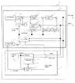
図1は、実施の形態1に係る画像処理装置30の構成図である。無人飛行機50に搭載される画像処理装置30は、GPS/INS計算部14と、所望のエリアの画像を取得する画像生成部15とから構成される。
FIG. 1 is a configuration diagram of an image processing apparatus 30 according to the first embodiment. The image processing device 30 mounted on the unmanned airplane 50 includes a GPS / INS calculation unit 14 and an image generation unit 15 that acquires an image of a desired area.
図1において、GPS/INS計算部14は、無人航空機50の角速度や加速度等の慣性情報を計測する姿勢角検出装置1と、図示しない測位衛星(GPS衛星)からの電波を受信して無人飛行機50の位置を取得する位置検出装置2と、姿勢角検出装置1が出力する慣性情報90を用いて速度情報を更新する速度更新計算部4と、速度更新計算部4が出力する速度情報と補正データを用いて無人飛行機50の位置を更新して、更新した位置と速度を出力する位置更新計算部5と、慣性情報90を用いて無人飛行機50の姿勢角を更新する姿勢角更新計算部6と、位置更新計算部5や姿勢角更新計算部6が算出する無人航空機50の位置、速度、姿勢角の誤差を推定して出力するフィルタ計算部11と、フィルタ計算部11が推定する各誤差情報に基づき各々の値を補正するバイアス補正部7と姿勢角補正部8と速度補正部9と位置補正部10とから構成されている。 In FIG. 1, a GPS / INS calculation unit 14 receives a radio wave from an attitude
また、自己位置補正部15は、GPS/INS計算部14が出力する無人飛行機50の位置、速度、姿勢角の情報をもとに画像取得装置3が撮影した画像をオルソ変換してオルソ画像を生成し、オルソ画像を地表面での位置情報を関連付けて保存し、また、過去に得られたオルソ画像と合成してパノラマ合成画像を生成する画像データベース12と、画像データベース12の画像データと画像取得装置3が撮影した撮影画像の一致度を調べる画像相関計算を行い、無人航空機50の位置、速度、姿勢角を推定する画像相関計算部13とから構成される。
ここで画像取得装置3は、例えば汎用の高解像度デジタルカメラである。また、オルソ変換については後で説明する。なお、上記GPS/INS計算部は複合計算測位部と対応し、上記姿勢角検出装置は慣性情報検出手段に対応する。また、上記画像取得装置は撮影手段に対応し、上記画像情報データベースは画像記憶手段に対応する。The self-position correcting unit 15 performs an ortho-transform on the image captured by the
Here, the
次に、無人航空機50が自律飛行し画像取得装置3が適宜地表の撮影を行うことで、地上の所望のエリアのパノラマ画像を取得する動作について説明する。
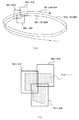
図2は、無人航空機を用いた飛行経路と所望エリアの空撮画像との関係を説明する図である。自律飛行は手動飛行に比べて正確に飛行経路を辿ることができる。そのため、図2に示すように無人航空機50は近い飛行経路で複周回飛行することができ、各周回の近接地点で撮像したそれぞれの静止画像(図2の周回1画像、周回2画像、周回3画像)を取得することができる。無人航空機50は、GPSや慣性センサの出力を元に、風等の外乱を抑制しながら、あらかじめ設定した所望のエリア上空の円または楕円軌道(飛行経路)を再現性良く旋回することが可能である。Next, an operation of acquiring a panoramic image of a desired area on the ground when the unmanned aircraft 50 autonomously flies and the
FIG. 2 is a diagram illustrating a relationship between a flight path using an unmanned aerial vehicle and an aerial image of a desired area. Autonomous flight can follow the flight path more accurately than manual flight. Therefore, as shown in FIG. 2, the unmanned aerial vehicle 50 can fly a plurality of times with close flight paths, and each still image (one or two images shown in FIG. 2, two or three images, or three or more) Image). The unmanned aerial vehicle 50 can turn with good reproducibility a circle or an elliptical orbit (flight path) over a desired area set in advance while suppressing disturbances such as wind based on the output of GPS and inertial sensors. is there.
無人航空機50の画像取得装置3は空撮画像の取得を行う。無人航空機50は低空飛行するため、市販のデジタルカメラを用いても高解像度の地表面の静止画像を得ることができる。画像取得装置3は無人航空機50の機体(無人航空機)に固定しておく。画像取得装置3を機体に固定することにより、無人航空機50の位置、姿勢角と画像取得装置3の位置、姿勢角とを対応付けることができる。
以下では、画像取得装置3の位置、姿勢角は無人航空機50の位置、姿勢角と同じとし、画像取得装置3の姿勢角に対応する座標系をカメラ座標系とする。ここでは、カメラ座標系において、X軸を無人航空機50の長手方向に中心軸にとり、Z軸をX軸が水平方向を向いた状態での鉛直上方にとり、Y軸を左手系の3軸直行座標系を構成するように設定する。また、世界座標系(例えば地球中心座標系WGS−84)から機体軸への変換に必要となるオイラー角(α、β、γ)により、無人航空機50の姿勢角を定義する。すなわち、カメラ座標軸(X、Y、Z)周りの回転角を各々(α,β,γ)=(ロール角、ピッチ角、ヨー角)とする。The
Hereinafter, the position and posture angle of the
位置検出装置2は、飛行中の機体の位置を測位する。位置検出装置2として例えばGPS受信機を用いる。
姿勢角検出装置1は、飛行中の機体の姿勢角を検出する。姿勢角検出装置1として例えばジャイロや加速度計などの慣性センサを用いる。The
The attitude
次に、GPS/INS計算部14の動作について説明する。GPS/INS計算部14は、位置検出装置2からの時系列の位置データ80と、姿勢角検出装置1からの時系列の慣性情報90とを用い、フィルタ計算部11において複合処理することにより、精度向上した機体の位置、速度および姿勢角を算出して出力する。フィルタ計算部11では、例えばカルマンフィルタにより複合処理を行い、各種の誤差推定値を算出して補正を行うようにする。
姿勢角検出装置1は、計測した慣性情報90の加速度情報を速度更新計算部4に出力し、また、慣性情報90の角速度情報を姿勢角更新計算部6に出力する。速度更新計算部4は飛行中の機体の速度を計算して位置更新計算部5に出力する。
位置更新計算部5は、加速度情報に基づき機体の位置と速度を算出し、算出した位置と速度を出力する。算出した機体の位置と速度はフィルタ計算部11に対してフィードバックされる。
姿勢角更新計算部6は、角速度情報により機体の姿勢角を算出し、算出した姿勢角を出力する。算出した機体の姿勢角はフィルタ計算部11に対してフィードバックされる。
フィルタ計算部11は、位置検出装置2からの位置データ80と、位置更新計算部5からの機体の位置と速度のデータと、姿勢角更新計算部6からの機体の姿勢角のデータとを入力して、姿勢角検出装置1のバイアス誤差推定値(例えば、累積されるジャイロセンサのセンサ誤差の推定値)、位置誤差の推定値、速度誤差の推定値、姿勢角誤差の推定値を各々算出する。バイアス補正部7、姿勢角補正部8、速度補正部9、位置補正部10の各々は、フィルタ計算部11からの上記誤差推定値により、姿勢角検出装置が出力する加速度と角速度、位置更新計算部の位置と速度、姿勢角更新計算部6が出力する姿勢角を補正する。Next, the operation of the GPS / INS calculation unit 14 will be described. The GPS / INS calculation unit 14 uses the time-series position data 80 from the
The posture
The position update calculation unit 5 calculates the position and speed of the aircraft based on the acceleration information, and outputs the calculated position and speed. The calculated position and speed of the aircraft are fed back to the filter calculation unit 11.
The attitude angle
The filter calculation unit 11 receives the position data 80 from the
一方、画像情報データベース12は、画像取得装置3が撮影した空撮画像のデータと、GPS/INS計算部14で算出した飛行状態情報のデータ(各撮影時の機体の位置情報、速度情報、の姿勢角情報)とを時刻同期をかけて、画像情報100として時系列に記憶する。時刻同期の方法としては、例えばGPS時間を基準にしてそれぞれのデータの取得タイミングに合わせて記録する等の手法が用いられる。 On the other hand, the
図3に、画像情報100の一例を示す。画像取得装置3が撮影した各画像(画像1、画像2、・・・、画像n)は、各々の撮影時の機体の位置情報(X、Y、Z)と、各撮影時の機体の姿勢角情報(ロール角α、ピッチ角β、ヨー角γ)と、撮影時刻とに関連付けられて、画像情報データベース12に記憶される。 FIG. 3 shows an example of the
画像情報データベース12はその内部に画像処理部121を有する。画像処理部121は画像情報データベース12に記憶された各々の画像にオルソ変換を施し、オルソ画像として画像情報データベース12に記憶する。オルソ画像は正射投影画像とも言われ、中心投影された画像を補正処理して正射投影した画像に変換した画像であり、あたかも真上から撮影したような画像のことをいう。また、複数のオルソ画像を部分的に重ね合わせたものをオルソモザイク画像、あるいはパノラマ合成画像という。 The
画像処理部121は、数1の回転並進式を用いて、撮影した画像の画像変換(オルソ変換)を行う。 The

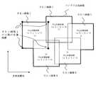
数1で示した回転並進式は、画像の回転に加えて画像の平行移動を行う。図4は、カメラ座標系と世界座標系(例えばWGS−84)との関係を示した図である。
図4において、画像処理部121は、まず、カメラの姿勢に対応するカメラ座標系X−Y−Z(原点0)で表され撮像面に写る空撮画像を地表面をX’−Y’平面とする世界座標系X’−Y’−Z’(原点0)に投影して、鉛直方向からみた撮像範囲を表す画像を生成する。そして、Tx、Ty、Tz分だけ平行移動する。平行移動量Tx、Ty、Tzは、図4の関係図において、数1による画像投影後に、長方形(または正方形)の画像範囲の中央に撮像範囲が位置するように、また、長方形(または正方形)の画像範囲と撮像範囲との間の余白部分が少なくなるように平行移動後のカメラ中心0(0x'、0y'、0z')を定めるとよい。オルソ変換を行うことにより、あたかもレベルフライトする航空機や人工衛星から撮影したような空撮画像を得ることができる。The rotational translation system shown in
In FIG. 4, the
画像処理部121は、変換後のオルソ画像と、オルソ画像(長方形または正方形)の中心となる位置座標(オルソ画像に写された地形画像の中心位置座標)とを、オルソ画像情報101として画像情報データベース12に記憶する。オルソ画像情報101の一例を図5に示す。 The
パノラマ合成画像は、このオルソ画像情報101(オルソ画像と、オルソ画像の世界座標系における中心位置座標)に基づき、オルソ画像を世界座標系に順次重ね合わせられるようにして作成される。図6は、パノラマ合成画像とオルソ画像との関係を示した図である。 The panorama composite image is created based on the ortho image information 101 (ortho image and center position coordinates of the ortho image in the world coordinate system) so that the ortho image can be sequentially superimposed on the world coordinate system. FIG. 6 is a diagram showing the relationship between the panorama composite image and the ortho image.
このようにして、無人飛行機50がGPS電波を受信できている間は、蓄積するINSの誤差推定と除去を行って無人飛行機50の高精度な位置情報と姿勢角情報を得て、所望のエリアの精度の高いパノラマ画像を取得することができる。 In this way, while the unmanned airplane 50 is able to receive GPS radio waves, the accumulated INS error is estimated and removed to obtain highly accurate position information and attitude angle information of the unmanned airplane 50 to obtain a desired area. High-accuracy panoramic images can be acquired.
次に、無人航空機50が飛行中にGPS電波が途絶えた場合に、無人飛行機50が位置と姿勢角を補正し所望のエリアのパノラマ画像を取得するまでの動作について、フロー図を用いて説明する。
前で述べたように、移動中にGPS電波が受信できない状況では、GPS/INS計算部14は累積するINSのセンサ誤差を除去できず、このため撮像取得装置が撮像した空撮画像と地上の位置との対応に誤差が生じて、パノラマ合成画像の精度が劣化するという問題が生じる。Next, an operation until the unmanned airplane 50 corrects the position and the attitude angle and acquires a panoramic image of a desired area when the GPS radio wave is interrupted while the unmanned airplane 50 is flying will be described with reference to a flowchart. .
As described above, in a situation where GPS radio waves cannot be received while moving, the GPS / INS calculation unit 14 cannot remove the accumulated INS sensor error, and therefore, the aerial image captured by the imaging acquisition device and the ground There arises a problem that an error occurs in the correspondence with the position and the accuracy of the panorama composite image is deteriorated.
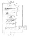
図7は、GPS衛星からのGPS電波が、上空の衛星と無人飛行機50との位置関係等により受信できない状況において、位置検出装置2が出力する位置情報によらず無人飛行機50の位置、姿勢角を補正する動作を説明するフロー図である。
ここではパノラマ合成画像生成の一例として、図8のように過去にパノラマ合成画像を取得済みのエリアの近傍のエリア(図8の点線で示したエリア)の画像を新たに取得することを想定する。FIG. 7 shows the position and attitude angle of the unmanned airplane 50 regardless of the position information output by the
Here, as an example of generating a panorama composite image, it is assumed that a new image of an area in the vicinity of an area where a panorama composite image has been acquired in the past as shown in FIG. 8 (area indicated by a dotted line in FIG. 8) is acquired. .
図7において、画像相関計算部13は、位置検出装置2が出力する測位結果を検知している。画像相関計算部13は、GPS電波の受信状況等により、位置検出装置2からの測位結果の出力がないことを検知すると(図7のS101)、画像生成部15による補正動作を開始する。
画像相関計算部13は、画像情報データベース12に対して画像取得装置3が撮影した空撮画像をデータベースに記憶する指示信号を出力する(S102)。
次に、画像相関計算部13は、画像取得装置3が撮影する空撮画像とパノラマ合成画像との間で画像相関計算を行い、画像の一致の度合いを示す相関値の計算を行う(S103)。画像相関計算は例えば画像間差分等の一般的な画像処理の手法を用いることができる。相関値の計算をする際、現在の絶対位置・姿勢角情報(GPS/INS計算部14が出力する位置、姿勢角の直近データ)をもとに、現在の取得画像の地表面における位置を推定し、この推定位置を相関値計算時の初期位置とする。この初期位置を中心として、北方向、東方向、地表面法線を軸とした回転方向に、予め設定した値分だけ画像をバイアス・回転させ、その都度相関値を計算する。
次に、得られた相関値の中で最も大きい相関値と予め設定した設定値との比較を行う。相関値が設定値以上である場合(S104)には、撮影した空撮画像が、既に合成し作成されているパノラマ合成画像の中の一部のエリアを撮影した空撮画像であり、画像が一致する地点であるとして、空撮画像が一致したパノラマ合成画像内のエリアの四隅の位置座標を抽出する(S105)。
ここで、S105で得た一致エリアの四隅の位置座標を[Xi、Yi、0](i=1〜4)と置く。また、求める機体位置座標を[P1、P2、P3]、求める姿勢角ベクトルを[D1、D2、D3]と置く。また姿勢角とカメラの四隅の方向への単位ベクトルを関係付けるカメラパラメータを[Cij](i=1〜4、j=1〜3、iは四隅・jは方向に対応するインデックス)とする。カメラパラメータ[Cij]は、機体へのカメラの取り付け角度やカメラの視野角に依存するパラメータであり、予め計測しておくことにより既知の値となる。以上諸量の関係式を数2に示す。In FIG. 7, the image
The image
Next, the image
Next, the largest correlation value among the obtained correlation values is compared with a preset set value. If the correlation value is greater than or equal to the set value (S104), the captured aerial image is an aerial image obtained by capturing a part of the panorama composite image that has already been synthesized and created. The position coordinates of the four corners of the area in the panorama composite image where the aerial images match are extracted as the matching points (S105).
Here, the position coordinates of the four corners of the coincidence area obtained in S105 are set as [Xi, Yi, 0] (i = 1 to 4). Also, the body position coordinates to be obtained are set as [P1, P2, P3], and the attitude angle vectors to be found are set as [D1, D2, D3]. A camera parameter that associates a unit vector in the direction of the posture angle and the four corners of the camera is [Cij] (i = 1 to 4, j = 1 to 3, i is the four corners and j is an index corresponding to the direction). The camera parameter [Cij] is a parameter that depends on the angle at which the camera is attached to the aircraft and the viewing angle of the camera, and becomes a known value by measuring in advance. The relational expression of various quantities is shown in
数2の計算式では計算上の未知係数として[Ui]を用いる。既知の量を[Xi、Yi、Cij]とすると、これら既知量を用いることで、数2に示す方程式を[P1、P2、P3、D1、D2、D3、Ui]について解くことができる。
以上より機体の位置、姿勢角を算出する。(S106)
次に、画像相関計算部13は、算出した位置、姿勢角をフィルタ計算部11に出力する(S107)。
フィルタ計算部11は、画像相関計算部13からの位置、姿勢角のデータを、GPS電波受信可能時に位置検出装置2が出力する位置のデータの代替として入力し、前に説明したフィルタ計算を行い、誤差推定値を算出する。In the formula (2), [Ui] is used as a calculation unknown coefficient. If the known quantities are [Xi, Yi, Cij], the equations shown in
From the above, the position and attitude angle of the aircraft are calculated. (S106)
Next, the image
The filter calculation unit 11 inputs the position and attitude angle data from the image
一方、S105において相関値が条件を満たさない時は、画像取得装置3はパノラマ合成画像にないエリアを撮影しているものとみなし、画像相関計算部13は、位置、姿勢角をフィルタ計算部11に出力せず、フィルタ計算部11は誤差推定を行わない。
無人航空機50による撮影を継続する場合は再びS101に戻り、S101〜S108の処理ステップを繰り返す。
なお、S101においてGPS電波を受信できる状況であれば、通常通り、位置検出装置2は測位した位置をフィルタ計算部11に出力する(S108)。On the other hand, when the correlation value does not satisfy the condition in S105, the
When photographing by the unmanned aircraft 50 is continued, the process returns to S101 again, and the processing steps of S101 to S108 are repeated.
If the GPS radio wave can be received in S101, the
このように、実施の形態1では、GPS電波の受信時には、姿勢角検出装置1と位置検出装置2とフィルタ計算部11とで構成されるフィルタ構成により各種誤差推定を行い、誤差推定により補正した位置のデータを用いて、パノラマ合成画像を取得する。
一方、GPS電波の受信ができない時には、画像相関計算部は、撮影した空撮画像と既にあるパノラマ合成画像との相関を調べ、相関が高いときには相関が高いパノラマ合成画像の位置座標から、無人航空機50の位置、姿勢角を算出し、フィルタ計算部に出力するようにした。そして、姿勢角検出装置1と画像相関計算部13とフィルタ計算部11とで構成されるフィルタ構成により各種誤差推定を行い、誤差推定により精度の高い位置、速度、姿勢角のデータを得られるようにした。
これにより、GPS電波の受信ができない時であっても、機体の位置と姿勢角の補正が可能であり、精度の高いパノラマ画像を取得することができる。As described above, in the first embodiment, when GPS radio waves are received, various error estimations are performed using the filter configuration including the attitude
On the other hand, when the GPS radio wave cannot be received, the image correlation calculation unit checks the correlation between the captured aerial image and the existing panoramic composite image, and when the correlation is high, the unmanned aircraft 50 positions and posture angles were calculated and output to the filter calculation unit. Various error estimations are performed by a filter configuration including the attitude
Thereby, even when GPS radio waves cannot be received, the position and attitude angle of the aircraft can be corrected, and a highly accurate panoramic image can be acquired.
実施の形態2.
実施の形態1では、画像取得装置が取得した空撮画像とパノラマ合成画像との相関を計算したが、画像取得装置から得られた空撮画像に、予め絶対位置が判っているランドマークが撮影されていた場合には、ランドマークの絶対位置をもとに無人航空機の位置と姿勢角を推定できる。実施の形態2では、空撮画像に写っているランドマークの絶対位置をもとに無人航空機の位置と姿勢角を推定する。
In
図9は、この発明の実施の形態1に係る画像処理装置30の構成を示す図である。実施の形態2の画像生成部15は、予め絶対位置が判っているランドマークとその絶対位置とが関連付けられたデータが格納されたランドマークデータベース16と、ランドマーク一致計算部17を備える。ランドマークは、例えば、高層ビルや橋、空港、グランドなど外観に特徴があるものである。なお、実施の形態1と同一あるいは相当する部分については同一番号を付してその説明を省略する。 FIG. 9 is a diagram showing a configuration of the image processing apparatus 30 according to the first embodiment of the present invention. The image generation unit 15 according to the second embodiment includes a
図10は、実施の形態2におけるGPS電波が受信できない状況において位置、姿勢角を補正する動作を説明するフロー図である。
図10において、画像相関計算部13は、位置検出装置2が出力する測位結果を検知している。画像相関計算部13は、GPS電波の受信状況等により、位置検出装置2からの測位結果の出力がないことを検知すると(S201)、画像生成部15による補正動作を開始する。
画像相関計算部13は、ランドマークデータベース16に対して画像取得装置3が撮影した空撮画像をデータベースに記憶する指示信号を出力する(S202)。
図10において、実施の形態2では空撮画像の中からランドマークを検索し(S203)、ランドマークが写っている場合は、ランドマークデータベース16よりそのランドマークの絶対位置を抽出する(S204)。
画像生成部15は、S205で得たランドマークの絶対位置から、無人航空機50の位置、姿勢角を算出する(S205)。
ここで、S205で得たランドマークの絶対位置座標を[Xi、Yi、0](i=1〜4)と置く。また、求める機体位置座標を[P1、P2、P3]、求める姿勢角ベクトルを[D1、D2、D3]と置く。画像上のランドマークの位置座標を画素点[Gi、Hi]とおくと、姿勢角と画素点方向への単位ベクトルを関係付けるカメラパラメータ[Cij](i=1〜4、j=1〜3、iはランドマーク番号・jは方向に対応するインデックス)は、画素点[Gi、Hi]の関数として書き表される(数3)。以上の諸量の関係式を数3に示す。FIG. 10 is a flowchart for explaining the operation of correcting the position and posture angle in a situation where GPS radio waves cannot be received in the second embodiment.
In FIG. 10, the image
The image
In FIG. 10, in the second embodiment, a landmark is searched from an aerial image (S203). If a landmark is shown, the absolute position of the landmark is extracted from the landmark database 16 (S204). .
The image generation unit 15 calculates the position and attitude angle of the unmanned aircraft 50 from the absolute position of the landmark obtained in S205 (S205).
Here, the absolute position coordinates of the landmark obtained in S205 are set as [Xi, Yi, 0] (i = 1 to 4). Also, the body position coordinates to be obtained are set as [P1, P2, P3], and the attitude angle vectors to be found are set as [D1, D2, D3]. When the position coordinates of the landmark on the image are set as pixel points [Gi, Hi], camera parameters [Cij] (i = 1 to 4, j = 1 to 3) for associating the posture angle with a unit vector in the pixel point direction. , I is a landmark number, j is an index corresponding to a direction), and is expressed as a function of the pixel point [Gi, Hi] (Equation 3).
また、数3の計算式では計算上の未知係数として[Ui]を用いる。既知の量を[Xi、Yi、Gi、Hi]とし、これらを用いると、数3に示す方程式を[Cij、P1、P2、P3、D1、D2、D3、Ui]について解くことができる。
以上より機体の位置、姿勢角を算出する(S206)。Further, in the calculation formula of
The position and attitude angle of the aircraft are calculated from the above (S206).
このように実施の形態2では、GPS電波の受信ができない時に、ランドマーク一致計算部17はオルソ画像中に予め絶対位置が判っているランドマークが撮影されているか否かを判定し、ランドマークが撮影されている場合にはそのランドマークの絶対位置から無人航空機50の位置、姿勢角を算出し、フィルタ計算部に出力するようにした。そして、姿勢角検出装置1と画像相関計算部13とフィルタ計算部11とで構成されるフィルタ構成により各種誤差推定を行い、誤差推定により精度の高い位置、速度、姿勢角のデータを得られるようにした。
これにより、GPS電波の受信ができない時であっても、位置と姿勢角の補正が可能であり、精度の高いパノラマ画像を取得することができる。As described above, in the second embodiment, when the GPS radio wave cannot be received, the landmark coincidence calculation unit 17 determines whether or not a landmark whose absolute position is known in advance is photographed in the ortho image. Is taken, the position and attitude angle of the unmanned aerial vehicle 50 are calculated from the absolute position of the landmark and output to the filter calculation unit. Various error estimations are performed by a filter configuration including the attitude
As a result, even when GPS radio waves cannot be received, the position and orientation angle can be corrected, and a highly accurate panoramic image can be acquired.
1 姿勢角検出装置、2 位置検出装置、3 画像取得装置、4 速度更新計算部、5 位置更新計算部、6 姿勢角更新計算部、7 バイアス補正部、8 姿勢角補正部、9 速度補正部、10 位置補正部、11 フィルタ計算部、12 画像データベース、14 GPS/INS計算部、15 画像生成部、16ランドマークデータベース、17ランドマーク一致計算部、30 画像処理装置、50 無人航空機、80 位置データ、90 慣性情報、100 画像情報、101 オルソ画像情報、121 画像処理部DESCRIPTION OF
Claims (4)
Translated fromJapanese測位衛星からの電波を受信して前記機体の位置を測位する位置検出手段が出力する位置情報と、前記機体の角速度や加速度を計測する慣性情報検出手段が出力する慣性情報とを複合処理して前記機体の位置と姿勢角を算出する複合計算測位部と、
地上を撮影する撮影手段と、前記撮影手段が撮影した撮影画像と前記複合計算測位部が算出した前記機体の位置と姿勢角とを関連付け前記撮影画像を貼り合わせて特定地域のパノラマ画像を生成して記憶する画像記憶手段とからなる画像生成部と、を備えた画像処理装置であって、
前記位置検出手段が機体の位置を測位できない場合において、前記画像生成部は、前記撮影手段が撮影する撮影画像と生成された前記パノラマ画像とを照合することで前記機体の位置を推定し、複合計算測位部は推定された機体の位置と前記慣性情報検出手段からの慣性情報とを複合処理して、前記機体の位置と姿勢角を算出することを特徴とする画像処理装置。It is mounted on the aircraft that flies multiple times over a specific area,
The position information output from the position detection means for receiving the radio wave from the positioning satellite and measuring the position of the aircraft is combined with the inertia information output from the inertia information detection means for measuring the angular velocity and acceleration of the aircraft. A compound calculation positioning unit for calculating the position and posture angle of the aircraft,
A panorama image of a specific area is generated by associating the photographing image which is photographed by the photographing means, the photographed image photographed by the photographing device and the position and posture angle of the aircraft calculated by the combined calculation positioning unit, and the photographed image. An image generation unit including an image storage unit that stores the image storage unit,
When the position detection unit cannot determine the position of the aircraft, the image generation unit estimates the position of the aircraft by comparing the captured image captured by the imaging unit with the generated panoramic image, and combines An image processing apparatus characterized in that the calculation positioning unit performs combined processing of the estimated position of the aircraft and the inertia information from the inertia information detection means to calculate the position and attitude angle of the aircraft.
Priority Applications (1)
| Application Number | Priority Date | Filing Date | Title |
|---|---|---|---|
| JP2007150549AJP2008304260A (en) | 2007-06-06 | 2007-06-06 | Image processing device |
Applications Claiming Priority (1)
| Application Number | Priority Date | Filing Date | Title |
|---|---|---|---|
| JP2007150549AJP2008304260A (en) | 2007-06-06 | 2007-06-06 | Image processing device |
Publications (1)
| Publication Number | Publication Date |
|---|---|
| JP2008304260Atrue JP2008304260A (en) | 2008-12-18 |
Family
ID=40233120
Family Applications (1)
| Application Number | Title | Priority Date | Filing Date |
|---|---|---|---|
| JP2007150549APendingJP2008304260A (en) | 2007-06-06 | 2007-06-06 | Image processing device |
Country Status (1)
| Country | Link |
|---|---|
| JP (1) | JP2008304260A (en) |
Cited By (33)
| Publication number | Priority date | Publication date | Assignee | Title |
|---|---|---|---|---|
| JP2010213214A (en)* | 2009-03-12 | 2010-09-24 | Brother Ind Ltd | Head-mounted display |
| CN101858746A (en)* | 2010-03-26 | 2010-10-13 | 航天东方红卫星有限公司 | A Method for Analytical Determination of the Attitude of Satellite-oriented Sun Orientation Targets Effectively Avoiding the Effect of Earth, Atmospheric Light |
| KR101010599B1 (en) | 2010-03-30 | 2011-01-25 | 새한항업(주) | Profile Inspection Method for Improving the Accuracy of Airborne Laser Surveying System |
| CN102163059A (en)* | 2011-04-27 | 2011-08-24 | 南京航空航天大学 | Attitude control system and attitude control method of variable thrust unmanned aerial vehicle |
| CN104714556A (en)* | 2015-03-26 | 2015-06-17 | 清华大学 | Intelligent course control method for unmanned plane |
| JP2015188150A (en)* | 2014-03-26 | 2015-10-29 | 株式会社衛星ネットワーク | Aerial imaging video distribution system and aerial imaging video distribution method |
| CN105573331A (en)* | 2016-01-13 | 2016-05-11 | 深圳市中科汉天下电子有限公司 | Method and apparatus for controlling overturning of multi-rotor aircraft |
| CN106303417A (en)* | 2016-08-12 | 2017-01-04 | 长沙冰眼电子科技有限公司 | Enhancing overall view monitoring method for unmanned platform |
| JP2017508166A (en)* | 2013-12-10 | 2017-03-23 | エスゼット ディージェイアイ テクノロジー カンパニー リミテッドSz Dji Technology Co.,Ltd | Sensor fusion |
| CN106546224A (en)* | 2016-10-14 | 2017-03-29 | 安徽协创物联网技术有限公司 | A kind of photography measurement method for spherical panoramic camera |
| JPWO2015163107A1 (en)* | 2014-04-25 | 2017-04-13 | ソニー株式会社 | Information processing apparatus, information processing method, and computer program |
| JP2017522622A (en)* | 2015-05-23 | 2017-08-10 | エスゼット ディージェイアイ テクノロジー カンパニー リミテッドSz Dji Technology Co.,Ltd | Sensor fusion using inertial and image sensors |
| JP2017522621A (en)* | 2015-06-26 | 2017-08-10 | エスゼット ディージェイアイ テクノロジー カンパニー リミテッドSz Dji Technology Co.,Ltd | Method, system, computer program product and apparatus for selecting operation mode of mobile platform |
| JP2018040785A (en)* | 2016-08-31 | 2018-03-15 | パナソニック インテレクチュアル プロパティ コーポレーション オブ アメリカPanasonic Intellectual Property Corporation of America | POSITION MEASUREMENT SYSTEM, POSITION MEASUREMENT METHOD, AND MOBILE ROBOT |
| JP2018512687A (en)* | 2015-03-03 | 2018-05-17 | プレナヴ インコーポレイテッド | Environmental scanning and unmanned aircraft tracking |
| US10001778B2 (en) | 2014-09-05 | 2018-06-19 | SZ DJI Technology Co., Ltd | Velocity control for an unmanned aerial vehicle |
| CN108225309A (en)* | 2016-12-21 | 2018-06-29 | 波音公司 | Enhance the method and apparatus of multiple raw sensor images by geographic registration |
| US10029789B2 (en) | 2014-09-05 | 2018-07-24 | SZ DJI Technology Co., Ltd | Context-based flight mode selection |
| CN108664037A (en)* | 2017-03-28 | 2018-10-16 | 精工爱普生株式会社 | The method of operating of head-mount type display unit and unmanned plane |
| WO2018198634A1 (en)* | 2017-04-28 | 2018-11-01 | ソニー株式会社 | Information processing device, information processing method, information processing program, image processing device, and image processing system |
| JP2018169368A (en)* | 2017-03-30 | 2018-11-01 | 国立研究開発法人宇宙航空研究開発機構 | Aircraft navigation device and aircraft navigation |
| JP2019023865A (en)* | 2018-07-12 | 2019-02-14 | エスゼット ディージェイアイ テクノロジー カンパニー リミテッドSz Dji Technology Co.,Ltd | Method, system, and program for performing error recovery |
| JP2019035670A (en)* | 2017-08-17 | 2019-03-07 | 株式会社Subaru | Own machine position measuring device, own machine position measuring method, and own machine position measuring program |
| KR20190075635A (en)* | 2017-12-21 | 2019-07-01 | 주식회사 한화 | Apparatus and method for generating stereoscopic image of flight model based on latitude-longitude coordinate |
| JP2019132672A (en)* | 2018-01-31 | 2019-08-08 | 田中 成典 | Three-dimensional model generation system |
| CN110414337A (en)* | 2019-06-21 | 2019-11-05 | 联创汽车电子有限公司 | Targeted attitude detection system and its detection method |
| US10565732B2 (en) | 2015-05-23 | 2020-02-18 | SZ DJI Technology Co., Ltd. | Sensor fusion using inertial and image sensors |
| JP2020042854A (en)* | 2019-11-29 | 2020-03-19 | エスゼット ディージェイアイ テクノロジー カンパニー リミテッドSz Dji Technology Co.,Ltd | System and method for selecting operation mode of mobile platform |
| JP2020112557A (en)* | 2014-10-17 | 2020-07-27 | ソニー株式会社 | Device, method and program |
| US10893190B2 (en) | 2017-02-02 | 2021-01-12 | PreNav, Inc. | Tracking image collection for digital capture of environments, and associated systems and methods |
| US10901419B2 (en) | 2014-09-05 | 2021-01-26 | SZ DJI Technology Co., Ltd. | Multi-sensor environmental mapping |
| WO2021053715A1 (en)* | 2019-09-17 | 2021-03-25 | 株式会社トラジェクトリー | Control system and control method |
| CN115909819A (en)* | 2021-09-30 | 2023-04-04 | 本田技研工业株式会社 | Unmanned moving body auxiliary system that returns to journey |
- 2007
- 2007-06-06JPJP2007150549Apatent/JP2008304260A/enactivePending
Cited By (62)
| Publication number | Priority date | Publication date | Assignee | Title |
|---|---|---|---|---|
| JP2010213214A (en)* | 2009-03-12 | 2010-09-24 | Brother Ind Ltd | Head-mounted display |
| CN101858746A (en)* | 2010-03-26 | 2010-10-13 | 航天东方红卫星有限公司 | A Method for Analytical Determination of the Attitude of Satellite-oriented Sun Orientation Targets Effectively Avoiding the Effect of Earth, Atmospheric Light |
| KR101010599B1 (en) | 2010-03-30 | 2011-01-25 | 새한항업(주) | Profile Inspection Method for Improving the Accuracy of Airborne Laser Surveying System |
| CN102163059A (en)* | 2011-04-27 | 2011-08-24 | 南京航空航天大学 | Attitude control system and attitude control method of variable thrust unmanned aerial vehicle |
| JP2017508166A (en)* | 2013-12-10 | 2017-03-23 | エスゼット ディージェイアイ テクノロジー カンパニー リミテッドSz Dji Technology Co.,Ltd | Sensor fusion |
| US10240930B2 (en) | 2013-12-10 | 2019-03-26 | SZ DJI Technology Co., Ltd. | Sensor fusion |
| JP2015188150A (en)* | 2014-03-26 | 2015-10-29 | 株式会社衛星ネットワーク | Aerial imaging video distribution system and aerial imaging video distribution method |
| US11250585B2 (en) | 2014-04-25 | 2022-02-15 | Sony Corporation | Information processing device, information processing method, and computer program |
| JP2019194903A (en)* | 2014-04-25 | 2019-11-07 | ソニー株式会社 | Information processing device, information processing method and computer program |
| US11657534B2 (en) | 2014-04-25 | 2023-05-23 | Sony Group Corporation | Information processing device, information processing method, and computer program |
| JPWO2015163107A1 (en)* | 2014-04-25 | 2017-04-13 | ソニー株式会社 | Information processing apparatus, information processing method, and computer program |
| US10001778B2 (en) | 2014-09-05 | 2018-06-19 | SZ DJI Technology Co., Ltd | Velocity control for an unmanned aerial vehicle |
| US11370540B2 (en) | 2014-09-05 | 2022-06-28 | SZ DJI Technology Co., Ltd. | Context-based flight mode selection |
| US10901419B2 (en) | 2014-09-05 | 2021-01-26 | SZ DJI Technology Co., Ltd. | Multi-sensor environmental mapping |
| US10845805B2 (en) | 2014-09-05 | 2020-11-24 | SZ DJI Technology Co., Ltd. | Velocity control for an unmanned aerial vehicle |
| US10029789B2 (en) | 2014-09-05 | 2018-07-24 | SZ DJI Technology Co., Ltd | Context-based flight mode selection |
| US11914369B2 (en) | 2014-09-05 | 2024-02-27 | SZ DJI Technology Co., Ltd. | Multi-sensor environmental mapping |
| US10421543B2 (en) | 2014-09-05 | 2019-09-24 | SZ DJI Technology Co., Ltd. | Context-based flight mode selection |
| JP7014243B2 (en) | 2014-10-17 | 2022-02-01 | ソニーグループ株式会社 | Equipment, methods and programs |
| US12385743B2 (en) | 2014-10-17 | 2025-08-12 | Sony Group Corporation | Position estimation device and position estimation method |
| US11668569B2 (en) | 2014-10-17 | 2023-06-06 | Sony Group Corporation | Position estimation device and position estimation method |
| JP2020112557A (en)* | 2014-10-17 | 2020-07-27 | ソニー株式会社 | Device, method and program |
| JP2018512687A (en)* | 2015-03-03 | 2018-05-17 | プレナヴ インコーポレイテッド | Environmental scanning and unmanned aircraft tracking |
| CN104714556A (en)* | 2015-03-26 | 2015-06-17 | 清华大学 | Intelligent course control method for unmanned plane |
| CN104714556B (en)* | 2015-03-26 | 2017-08-11 | 清华大学 | UAV Intelligent course heading control method |
| JP2017522622A (en)* | 2015-05-23 | 2017-08-10 | エスゼット ディージェイアイ テクノロジー カンパニー リミテッドSz Dji Technology Co.,Ltd | Sensor fusion using inertial and image sensors |
| US10565732B2 (en) | 2015-05-23 | 2020-02-18 | SZ DJI Technology Co., Ltd. | Sensor fusion using inertial and image sensors |
| US11465743B2 (en) | 2015-06-26 | 2022-10-11 | SZ DJI Technology Co., Ltd. | System and method for selecting an operation mode of a mobile platform |
| JP2017522621A (en)* | 2015-06-26 | 2017-08-10 | エスゼット ディージェイアイ テクノロジー カンパニー リミテッドSz Dji Technology Co.,Ltd | Method, system, computer program product and apparatus for selecting operation mode of mobile platform |
| US10730618B2 (en) | 2015-06-26 | 2020-08-04 | SZ DJI Technology Co., Ltd. | System and method for selecting an operation mode of a mobile platform |
| CN105573331A (en)* | 2016-01-13 | 2016-05-11 | 深圳市中科汉天下电子有限公司 | Method and apparatus for controlling overturning of multi-rotor aircraft |
| CN106303417B (en)* | 2016-08-12 | 2020-03-27 | 长沙冰眼电子科技有限公司 | Enhanced panoramic monitoring method for unmanned platform |
| CN106303417A (en)* | 2016-08-12 | 2017-01-04 | 长沙冰眼电子科技有限公司 | Enhancing overall view monitoring method for unmanned platform |
| JP2018040785A (en)* | 2016-08-31 | 2018-03-15 | パナソニック インテレクチュアル プロパティ コーポレーション オブ アメリカPanasonic Intellectual Property Corporation of America | POSITION MEASUREMENT SYSTEM, POSITION MEASUREMENT METHOD, AND MOBILE ROBOT |
| CN106546224A (en)* | 2016-10-14 | 2017-03-29 | 安徽协创物联网技术有限公司 | A kind of photography measurement method for spherical panoramic camera |
| JP2018139105A (en)* | 2016-12-21 | 2018-09-06 | ザ・ボーイング・カンパニーThe Boeing Company | Method and apparatus for enhancement of raw sensor image via geographic registration |
| JP7403210B2 (en) | 2016-12-21 | 2023-12-22 | ザ・ボーイング・カンパニー | Method and apparatus for raw sensor image enhancement through georegistration |
| CN108225309A (en)* | 2016-12-21 | 2018-06-29 | 波音公司 | Enhance the method and apparatus of multiple raw sensor images by geographic registration |
| CN108225309B (en)* | 2016-12-21 | 2023-09-26 | 波音公司 | Method and apparatus for enhancing multiple raw sensor images by geographic registration |
| US10893190B2 (en) | 2017-02-02 | 2021-01-12 | PreNav, Inc. | Tracking image collection for digital capture of environments, and associated systems and methods |
| US11046429B2 (en) | 2017-03-28 | 2021-06-29 | Seiko Epson Corporation | Head mounted display and method for maneuvering vehicle |
| CN108664037A (en)* | 2017-03-28 | 2018-10-16 | 精工爱普生株式会社 | The method of operating of head-mount type display unit and unmanned plane |
| JP2018169368A (en)* | 2017-03-30 | 2018-11-01 | 国立研究開発法人宇宙航空研究開発機構 | Aircraft navigation device and aircraft navigation |
| US20220237738A1 (en)* | 2017-04-28 | 2022-07-28 | Sony Group Corporation | Information processing device, information processing method, information processing program, image processing device, and image processing system for associating position information with captured images |
| JP7556383B2 (en) | 2017-04-28 | 2024-09-26 | ソニーグループ株式会社 | Information processing device, information processing method, information processing program, image processing device, and image processing system |
| US20230419445A1 (en)* | 2017-04-28 | 2023-12-28 | Sony Group Corporation | Information processing device, information processing method, information processing program, image processing device, and image processing system for associating position information with captured images |
| US11341608B2 (en) | 2017-04-28 | 2022-05-24 | Sony Corporation | Information processing device, information processing method, information processing program, image processing device, and image processing system for associating position information with captured images |
| WO2018198634A1 (en)* | 2017-04-28 | 2018-11-01 | ソニー株式会社 | Information processing device, information processing method, information processing program, image processing device, and image processing system |
| US11756158B2 (en) | 2017-04-28 | 2023-09-12 | Sony Group Corporation | Information processing device, information processing method, information processing program, image processing device, and image processing system for associating position information with captured images |
| JP7251474B2 (en) | 2017-04-28 | 2023-04-04 | ソニーグループ株式会社 | Information processing device, information processing method, information processing program, image processing device, and image processing system |
| JPWO2018198634A1 (en)* | 2017-04-28 | 2020-03-05 | ソニー株式会社 | Information processing apparatus, information processing method, information processing program, image processing apparatus, and image processing system |
| JP2019035670A (en)* | 2017-08-17 | 2019-03-07 | 株式会社Subaru | Own machine position measuring device, own machine position measuring method, and own machine position measuring program |
| US10838076B2 (en) | 2017-08-17 | 2020-11-17 | Subaru Corporation | Self-position measuring device, self-position measuring method, and non-transitory storage medium |
| KR20190075635A (en)* | 2017-12-21 | 2019-07-01 | 주식회사 한화 | Apparatus and method for generating stereoscopic image of flight model based on latitude-longitude coordinate |
| KR102037504B1 (en) | 2017-12-21 | 2019-10-28 | 주식회사 한화 | Apparatus and method for generating stereoscopic image of flight model based on latitude-longitude coordinate |
| JP2019132672A (en)* | 2018-01-31 | 2019-08-08 | 田中 成典 | Three-dimensional model generation system |
| JP2019023865A (en)* | 2018-07-12 | 2019-02-14 | エスゼット ディージェイアイ テクノロジー カンパニー リミテッドSz Dji Technology Co.,Ltd | Method, system, and program for performing error recovery |
| CN110414337A (en)* | 2019-06-21 | 2019-11-05 | 联创汽车电子有限公司 | Targeted attitude detection system and its detection method |
| CN110414337B (en)* | 2019-06-21 | 2023-12-05 | 上海汽车工业(集团)总公司 | Target attitude detection system and detection method thereof |
| WO2021053715A1 (en)* | 2019-09-17 | 2021-03-25 | 株式会社トラジェクトリー | Control system and control method |
| JP2020042854A (en)* | 2019-11-29 | 2020-03-19 | エスゼット ディージェイアイ テクノロジー カンパニー リミテッドSz Dji Technology Co.,Ltd | System and method for selecting operation mode of mobile platform |
| CN115909819A (en)* | 2021-09-30 | 2023-04-04 | 本田技研工业株式会社 | Unmanned moving body auxiliary system that returns to journey |
Similar Documents
| Publication | Publication Date | Title |
|---|---|---|
| JP2008304260A (en) | Image processing device | |
| US11099030B2 (en) | Attitude estimation apparatus, attitude estimation method, and observation system | |
| EP3454008B1 (en) | Survey data processing device, survey data processing method, and survey data processing program | |
| KR100761011B1 (en) | Posture Correction Apparatus and Method for Inertial Navigation System Using Camera-type Solar Sensor | |
| AU2003244321B8 (en) | Picked-up image display method | |
| Mostafa et al. | Direct positioning and orientation systems: How do they work? What is the attainable accuracy | |
| JP2008186145A (en) | Aerial image processing apparatus and aerial image processing method | |
| US20110282580A1 (en) | Method of image based navigation for precision guidance and landing | |
| KR102075028B1 (en) | Unmanned High-speed Flying Precision Position Image Acquisition Device and Accurate Position Acquisition Method Using the same | |
| JP4448187B2 (en) | Image geometric correction method and apparatus | |
| KR100556103B1 (en) | Aerial Photography Method Using Automatic Photography System | |
| CN102322859B (en) | Aerial inertial navigation measurement system and attitude correction method | |
| KR101160454B1 (en) | Construction method of 3D Spatial Information using position controlling of UAV | |
| Toth et al. | Performance analysis of the airborne integrated mapping system (AIMS) | |
| US20170074678A1 (en) | Positioning and orientation data analysis system and method thereof | |
| RU2584368C1 (en) | Method of determining control values of parameters of spatial-angular orientation of aircraft on routes and pre-aerodrome zones in flight tests of pilot-navigation equipment and system therefor | |
| CN104360362A (en) | Method and system for positioning observed object via aircraft | |
| KR101224830B1 (en) | Portable Multi-Sensor System for Acquiring Georeferenced Images and Method thereof | |
| CN110296688A (en) | A kind of detecting one inclination aerial survey gondola based on passive geographic positioning technology | |
| CN110736457A (en) | An integrated navigation method based on Beidou, GPS and SINS | |
| Zhou et al. | Civil UAV system for earth observation | |
| Wierzbicki et al. | Determining the elements of exterior orientation in aerial triangulation processing using UAV technology | |
| CN118980373A (en) | A visual-inertial integrated navigation method for aircraft | |
| KR20250028773A (en) | Dead Reckoning System and Automatic Returning Method for Aircraft including the same | |
| JP7333565B1 (en) | Aircraft and method of controlling the aircraft |