JP2008302457A - Portable electric tool - Google Patents
Portable electric toolDownload PDFInfo
- Publication number
- JP2008302457A JP2008302457AJP2007151149AJP2007151149AJP2008302457AJP 2008302457 AJP2008302457 AJP 2008302457AJP 2007151149 AJP2007151149 AJP 2007151149AJP 2007151149 AJP2007151149 AJP 2007151149AJP 2008302457 AJP2008302457 AJP 2008302457A
- Authority
- JP
- Japan
- Prior art keywords
- battery pack
- housing
- elastic body
- holder
- pack holder
- Prior art date
- Legal status (The legal status is an assumption and is not a legal conclusion. Google has not performed a legal analysis and makes no representation as to the accuracy of the status listed.)
- Granted
Links
- 238000003780insertionMethods0.000claimsdescription15
- 230000037431insertionEffects0.000claimsdescription15
- 239000002861polymer materialSubstances0.000claimsdescription6
- 239000000463materialSubstances0.000description8
- 238000000034methodMethods0.000description7
- 230000001902propagating effectEffects0.000description5
- 239000013013elastic materialSubstances0.000description2
- 239000002184metalSubstances0.000description2
- 239000011347resinSubstances0.000description2
- 229920005989resinPolymers0.000description2
- 230000004913activationEffects0.000description1
- 230000002238attenuated effectEffects0.000description1
- WABPQHHGFIMREM-UHFFFAOYSA-Nlead(0)Chemical compound[Pb]WABPQHHGFIMREM-UHFFFAOYSA-N0.000description1
- 238000012986modificationMethods0.000description1
- 230000004048modificationEffects0.000description1
- 230000002093peripheral effectEffects0.000description1
- 230000009466transformationEffects0.000description1
Images


Classifications
- B—PERFORMING OPERATIONS; TRANSPORTING
- B25—HAND TOOLS; PORTABLE POWER-DRIVEN TOOLS; MANIPULATORS
- B25F—COMBINATION OR MULTI-PURPOSE TOOLS NOT OTHERWISE PROVIDED FOR; DETAILS OR COMPONENTS OF PORTABLE POWER-DRIVEN TOOLS NOT PARTICULARLY RELATED TO THE OPERATIONS PERFORMED AND NOT OTHERWISE PROVIDED FOR
- B25F5/00—Details or components of portable power-driven tools not particularly related to the operations performed and not otherwise provided for
- B25F5/006—Vibration damping means
- Y—GENERAL TAGGING OF NEW TECHNOLOGICAL DEVELOPMENTS; GENERAL TAGGING OF CROSS-SECTIONAL TECHNOLOGIES SPANNING OVER SEVERAL SECTIONS OF THE IPC; TECHNICAL SUBJECTS COVERED BY FORMER USPC CROSS-REFERENCE ART COLLECTIONS [XRACs] AND DIGESTS
- Y02—TECHNOLOGIES OR APPLICATIONS FOR MITIGATION OR ADAPTATION AGAINST CLIMATE CHANGE
- Y02E—REDUCTION OF GREENHOUSE GAS [GHG] EMISSIONS, RELATED TO ENERGY GENERATION, TRANSMISSION OR DISTRIBUTION
- Y02E60/00—Enabling technologies; Technologies with a potential or indirect contribution to GHG emissions mitigation
- Y02E60/10—Energy storage using batteries
Landscapes
- Engineering & Computer Science (AREA)
- Mechanical Engineering (AREA)
- Battery Mounting, Suspending (AREA)
- Portable Power Tools In General (AREA)
- Connection Of Batteries Or Terminals (AREA)
Abstract
Translated fromJapaneseDescription
Translated fromJapanese本発明は、着脱可能な電池パックを電源とする可搬型の電動工具に関する。 The present invention relates to a portable power tool that uses a detachable battery pack as a power source.
着脱可能な電池パックを電源とする可搬型の動力工具では、電動工具の動作中に電動工具と電池パックが相対的に振動し、電動工具や電池パックが損傷を受けることがある。あるいは、電池パックの出力端子とそれに接続する電動工具の接続端子との間で、接触不良が生じることがある。
上記の問題に対して、特許文献1には、電池パックの挿入口内の電池パックと当接する位置に、伸縮自在の弾性体を設ける技術が記載されている。そして、この技術によれば、電池パックの振動が防止されることによって、振動による摩擦熱で電動工具や電池パックが熱変形することを防止できると説明されている。
また、特許文献2には、電動工具の接続端子を摺動可能に設けておき、電動工具の接続端子を電池パックと一緒に振動可能にする技術が記載されている。そして、この技術によれば、電動工具と電池パックの端子間で接触不良が生じることを防止できると説明されている。In a portable power tool that uses a detachable battery pack as a power source, the power tool and the battery pack may vibrate relatively during operation of the power tool, and the power tool and the battery pack may be damaged. Or a contact failure may arise between the output terminal of a battery pack, and the connection terminal of the electric tool connected to it.
With respect to the above problem,
Patent Document 2 describes a technique in which a connection terminal of an electric tool is provided slidably and the connection terminal of the electric tool can be vibrated together with a battery pack. And it is described that according to this technique, it can prevent that a contact failure arises between the terminal of an electric tool and a battery pack.
特許文献1の技術では、弾性体の変形に伴って電動工具と電池パックが相対的に変位した時に、電動工具の接続端子と電池パックの出力端子が相対的に変位することから、両端子間で接触不良が生じやすい。また、電池パックの着脱時に、弾性体が損傷を受けやすいという問題もある。
特許文献2の技術では、電動工具の動作中に電動工具と電池パックが依然として相対的に振動することから、その振動によって電動工具や電池パックが損傷を受けることがある。特に、電池パックが強い振動を受け続けると、電池パック内の電池セルや電気回路が損傷を受けることもある。その結果、電池セルが早期に劣化するといった問題や、漏電が発生するといった問題が生じる。
本発明は、上記の問題を解決する。本発明は、電動工具と電池パックの端子間の接触不良を招くことなく、電動工具の動作中に電池パックが振動することを防止する技術を提供する。In the technique of
In the technique of Patent Document 2, since the electric tool and the battery pack still vibrate relatively during the operation of the electric tool, the electric tool and the battery pack may be damaged by the vibration. In particular, if the battery pack continues to receive strong vibrations, the battery cells and electrical circuits in the battery pack may be damaged. As a result, the problem that a battery cell deteriorates early and the problem that electric leakage generate | occur | produce arise.
The present invention solves the above problems. The present invention provides a technique for preventing the battery pack from vibrating during the operation of the power tool without causing poor contact between the terminals of the power tool and the battery pack.
本発明によって具現化される電動工具は、着脱可能な電池パックを電源とする可搬型の電動工具であって、工具を動作させるモータと、前記モータを収容しているハウジングと、前記ハウジングによって支持されている弾性体と、前記弾性体によって支持されている電池パック保持体を備えている。そして、前記電池パック保持体には、電池パックのケースと着脱可能に係合する係合部と、前記係合部によって装着された電池パックの出力端子と電気的に接続する接続端子が設けられていることを特徴とする。 An electric tool embodied by the present invention is a portable electric tool that uses a detachable battery pack as a power source, and includes a motor that operates the tool, a housing that houses the motor, and a support that is supported by the housing. And a battery pack holder supported by the elastic body. The battery pack holder is provided with an engaging portion that is detachably engaged with the case of the battery pack, and a connection terminal that is electrically connected to an output terminal of the battery pack attached by the engaging portion. It is characterized by.
この電動工具では、モータを収容しているハウジングと電池パックを保持する電池パック保持体との間に弾性体が配設されており、電池パック保持体が弾性体を介してハウジング接続された構成となっている。それにより、電動工具の動作中にハウジングで振動が発生しても、その振動が電池パック保持体や電池パックに伝播することを防止することができる。電池パック保持体と電池パックが相対的に強く振動することもないので、電池パック保持体に設けられた接続端子は電池パックの出力端子に接触し続けることができる。
この電動工具によると、電動工具と電池パックの端子間の接触不良を招くことなく、電動工具の動作中に電池パックが振動することを防止することができる。In this electric power tool, an elastic body is disposed between a housing that houses a motor and a battery pack holder that holds the battery pack, and the battery pack holder is connected to the housing via the elastic body. It has become. Thereby, even if vibration is generated in the housing during the operation of the electric power tool, the vibration can be prevented from propagating to the battery pack holder or the battery pack. Since the battery pack holder and the battery pack do not vibrate relatively strongly, the connection terminals provided on the battery pack holder can continue to contact the output terminals of the battery pack.
According to this power tool, it is possible to prevent the battery pack from vibrating during the operation of the power tool without causing poor contact between the terminals of the power tool and the battery pack.
上記した電動工具において、前記ハウジングは、前記モータを収容しているハウジング胴部と、そのハウジング胴部から伸びるグリップ部を備えていることが好ましい。この場合、前記電池パック保持体は、前記弾性体を介して前記グリップ部の先端に接続されていることが好ましい。
この電動工具によると、電池パック保持体がグリップ部の近くに配置されるので、電池パック保持体がハウジングに対して揺動しても、作業者が電動工具から受ける力が大きく変化することがない。作業者は、電動工具を容易に把持し続けることができる。In the above-described electric power tool, it is preferable that the housing includes a housing body portion that houses the motor and a grip portion that extends from the housing body portion. In this case, it is preferable that the battery pack holder is connected to the tip of the grip portion via the elastic body.
According to this electric tool, since the battery pack holder is disposed near the grip portion, even if the battery pack holder swings with respect to the housing, the force received by the operator from the electric tool may greatly change. Absent. The operator can easily hold the power tool.
上記した電動工具において、前記弾性体は、前記ハウジング又は電池パック保持体によって囲繞されていることが好ましい。
この電動工具によると、弾性体が外部の物体との接触によって損傷することが防止される。In the electric tool described above, it is preferable that the elastic body is surrounded by the housing or the battery pack holder.
According to this power tool, the elastic body is prevented from being damaged by contact with an external object.
上記した電動工具において、前記ハウジングと電池パック保持体の一方には突出部が形成されているとともに、他方には前記突出部が挿入されている挿入穴が形成されていることが好ましい。そして、前記突出部と前記挿入穴の一方の側面にはフランジ部が形成されているとともに、他方の側面にはそのフランジ部を収容している溝部が形成されていることが好ましい。そして、前記弾性体は、前記フランジ部と溝部の間に介在していることが好ましい。
この電動工具によると、電池パック保持体がハウジングに対して様々な方向に変位可能に接続される。それにより、ハウジングから電池パック保持体へ振動が伝播することを顕著に防止することができる。In the above-described electric tool, it is preferable that a projection is formed on one of the housing and the battery pack holder, and an insertion hole into which the projection is inserted is formed on the other. And it is preferable that the flange part is formed in one side surface of the said protrusion part and the said insertion hole, and the groove part which accommodates the flange part is formed in the other side surface. And it is preferable that the said elastic body is interposed between the said flange part and a groove part.
According to this electric tool, the battery pack holder is connected to the housing so as to be displaceable in various directions. Thereby, it is possible to remarkably prevent vibration from propagating from the housing to the battery pack holder.
上記した電動工具において、前記弾性体は、ゴム弾性を有する高分子材料によって形成されていることが好ましい。なお、ゴム弾性を有する高分子材料は、ゴム材料に限定されるものではない。
ゴム弾性を有する高分子材料は、加えられた力に対して比較的に大きく変形することができる。ゴム弾性を有する高分子材料によって弾性体を形成することにより、ハウジングから電池パック保持体へ振動が伝播することをより顕著に防止することができる。In the above-described electric power tool, it is preferable that the elastic body is formed of a polymer material having rubber elasticity. The polymer material having rubber elasticity is not limited to the rubber material.
A polymer material having rubber elasticity can be deformed relatively greatly with respect to an applied force. By forming the elastic body from a polymer material having rubber elasticity, it is possible to more significantly prevent vibration from propagating from the housing to the battery pack holder.
上記した電動工具において、前記弾性体の表面に、複数の突起が形成されていることが好ましい。
弾性体の表面に複数の突起が形成されていると、弾性体は加えられた力に対してより大きく変形することが可能となる。そのことから、ハウジングから電池パック保持体へ振動が伝播することをより顕著に防止することができる。In the above-described electric tool, it is preferable that a plurality of protrusions are formed on the surface of the elastic body.
When a plurality of protrusions are formed on the surface of the elastic body, the elastic body can be more greatly deformed with respect to the applied force. Therefore, it is possible to prevent the vibration from propagating from the housing to the battery pack holder more remarkably.
本発明により、電池パックを電源とする様々な電動工具において、電池パックが振動することを防止することが可能となる。電池パックが早期に故障することを防止し、電池パックの寿命を有意に延ばすことが可能となる。 According to the present invention, it is possible to prevent the battery pack from vibrating in various power tools using the battery pack as a power source. It is possible to prevent the battery pack from failing early and to significantly extend the life of the battery pack.
最初に、以下に説明する実施例の主要な特徴を列記する。
(特徴1) 電池パック保持体には、電池パックの出力端子と電気的に接続する接続端子が固定されている。電池パック保持体に固定された接続端子は、ハウジングに設けられたトリガスイッチやモータとリード線を介して接続されている。
(特徴2) 弾性体は、ゴム材料で形成されている。
(特徴3) 弾性体のハウジングとの接触面及び/又は電池パック保持体との接触面には、複数の突起が形成されている。
(特徴4) 電池パック保持体は、ハウジングと同じ材料で形成されている。First, the main features of the embodiments described below are listed.
(Feature 1) A connection terminal that is electrically connected to an output terminal of the battery pack is fixed to the battery pack holder. The connection terminal fixed to the battery pack holder is connected to a trigger switch or motor provided in the housing via a lead wire.
(Feature 2) The elastic body is made of a rubber material.
(Characteristic 3) A plurality of protrusions are formed on the contact surface of the elastic body with the housing and / or the contact surface with the battery pack holder.
(Feature 4) The battery pack holder is formed of the same material as the housing.
本発明を実施した電動工具について図面を参照しながら説明する。本実施例の電動工具は、作業者が把持した状態で使用する可搬型の電動工具であり、特にボルト類を締結するための締結工具である。
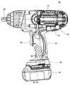
図1は、電動工具10の外観(一部断面図)を示す側面図である。図1に示すように、電動工具10は、ボルト類に係合する工具ビット(図示省略)が取付けられる工具軸24と、工具軸を回転させるモータ12と、モータ12を収容しているハウジング14を備えている。ハウジング14は、モータ12や工具軸24を収容しているハウジング胴部16と、ハウジング胴部16から略直交するように伸びるグリップ部18を備えている。グリップ部18には、起動スイッチであるトリガスイッチ22が設けられている。ハウジング14やトリガスイッチ22は、樹脂材料によって形成されている。
グリップ部18の先端(反ハウジング胴部16側の端部)には、電池パック保持体30が設けられている。図2に示すように、電池パック保持体30は、その正面(図1、図2の左側)から電池パック70を着脱できるように構成されている。電動工具10は、電池パック70を電源とする電動工具であり、電池パック保持体30に装着された電池パック70からの電力によって動作する。電池パック保持体30は、ハウジング14と同じ樹脂材料によって形成されている。A power tool embodying the present invention will be described with reference to the drawings. The power tool of the present embodiment is a portable power tool that is used while being held by an operator, and is particularly a fastening tool for fastening bolts.
FIG. 1 is a side view showing the external appearance (partially sectional view) of the
A
電動工具10を詳細に説明する前に、図7、図8を参照して電池パック70の構成について説明しておく。図7は、電池パック70の側面図を示しており、電池パック70の平面図を示している。図7、図8に示すように、電池パック70は、複数の電池セル(図示されない)を収容しているケース72を備えている。ケース72の上部には、側方に突出する一対のレール部74と、ラッチ部材76が設けられている。ラッチ部材76は、ばね部材によって上方に付勢されている。また、ケース72の上部には、各種の電気端子を収容している端子収容部80が形成されている。端子収容部80には、複数のスリット82a、82bが形成されている。一つのスリット82a内には、正極の出力端子84aが配設されている。一つのスリット82b内には、負極の出力端子84bが配設されている。電池パック70は、正極の出力端子84aと負極の出力端子84bとの間に略18ボルトの電圧を出力することができる。以下、正極の出力端子84aと負極の出力端子84bを、単に出力端子84a、84bと総称することがある。 Before describing the
図3、図4を参照して、電池パック保持体30の構成について説明する。図3は、正面(図1の左側)から見た電池パック保持体30を示す正面図である。即ち、図3は、電池パック70の挿入方向から見た電池パック保持体30を示している。図4は、下方から見た電池パック保持体30を示す底面図である。図4では、電池パック70が上方から下方に挿入される。
図3、図4に示すように、電池パック保持体30には、一対のレール部38と係合凹部39が形成されている。一対のレール部38は、電池パック70の挿入方向に伸びている。一対のレール部38は、電池パック70のレール部74と係合し、電池パック70をスライド可能に支持することができる。電池パック70が電池パック保持体30に完全に挿入されると(図1に示す状態)、電池パック70のラッチ部材76が電池パック保持体30の係合凹部39に係合する。それにより、電池パック70が電池パック保持体30に固定される。このように、電池パック保持体30には、電池パック70のケース72と係合して電池パック70を固定する係合構造が設けられている。The configuration of the
As shown in FIGS. 3 and 4, the
電池パック保持体30には、端子支持体50が設けられている。端子支持体50は、電池パック保持体30に固定されている。端子支持体50には、電池パック70の出力端子84a、84bと接続するための一対の接続端子52が形成されている。接続端子52は、リード線(図示されない)を介してハウジング14内のトリガスイッチ22やモータ12に電気的に接続されている。一対の接続端子52のそれぞれは、金属製の板状部材である。一対の接続端子52は、電池パック70が電池パック保持体30に挿入された時に、電池パック70のスリット82a、82bにそれぞれ侵入し、電池パック70の出力端子84a、84bにそれぞれ接触する。それにより、電動工具10と電池パック70が電気的に接続される。
電池パック70の出力端子84a、84bは、電池パック保持体30の接続端子52との接触に伴って弾性変形するように形成されている。電池パック保持体30の接続端子52と電池パック70の出力端子84a、84bは、出力端子84a、84bの弾性力(復元力)によって比較的に強く当接し合うようになっている。A
The
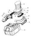
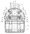
図5は、電池パック保持体30を分解した状態を示している。図6は、図1のVI−VI線断面図を示している。図5、図6に示すように、電池パック保持体30は、グリップ部18を含むハウジング14とは別の部材で構成されている。そして、ハウジング14と電池パック保持体30との間には、弾性体40が介挿されている。弾性体40が変形することによって、電池パック保持体30はハウジング14に対して相対変位可能になっている。
図5、図6を参照しながら、ハウジング14のグリップ部18と電池パック保持体30とを接続している構造について詳細に説明する。グリップ部18の先端には、突出部20が設けられている。突出部20の側面には、突出部20の略全体を周回するように溝21が形成されている。一方、電池パック保持体30には、突出部20が挿入されている挿入穴34が形成されている。挿入穴34の開口部には、内側に膨出している内向きフランジ36が形成されている。図6に示されるように、内向きフランジ36の一部は、グリップ部18に形成された突出部20の溝21内に収容されている。
グリップ部18に形成された突出部20の溝21と、電池パック保持体30に形成された挿入穴34の内向きフランジ36との間には、弾性体40が配設されている。弾性体40は、内向きフランジ36の上面、下面、内周縁を覆っており、グリップ部18と電池パック保持体30が直接的に接触することを禁止する。電池パック保持体30は、グリップ部18に支持された弾性体40のみによって支持されている。FIG. 5 shows a state in which the
A structure in which the
An
弾性体40は、ゴム材料で形成されている。弾性体40は、ゴム弾性を有する弾性部材であるとともに、粘弾性を有する弾性部材でもある。弾性体40がゴム弾性を有することから、弾性体40は加えられた力に対して比較的に大きく変形することができる。また、弾性体40が粘弾性を有することから、変形時に加えられたエネルギーを減衰させることができる。なお、弾性体40は、ゴム材料に限られず、他の弾性材料でも形成することができる。ただし、金属等の弾性材料よりも、変形量の大きなゴム弾性を有する高分子材料(ゴム材料に限られない)で形成することが好ましい。
弾性体40の表面には、複数の突起42が形成されている。それにより、弾性体40は、加えられた力に対してより大きく変形できるようになっている。本実施例では、弾性体40のハウジング14(詳しくは溝21)との接触面に複数の突起を形成しているが、電池パック保持体30との接触面にも同様に形成することができる。The
A plurality of
以上のように、本実施例の電動工具では、電池パック70を保持する電池パック保持体30が、弾性体40を介してハウジング14に接続されている。それにより、モータや工具の動作に伴ってハウジング14で振動が発生しても、その振動が電池パック70まで伝播することが防止される。電池パック70が激しく振動することがないので、電池パック70のケース72、電池セル、内部回路等が損傷することを防止することができる。
本実施例の電動工具10では、動作時にハウジング14で振動が発生しても、電池パック保持体30と電池パック70が相対的に強く振動することがない。そのことから、電池パック保持体30に設けられている接続端子52と、電池パック70の出力端子84a、84bとの位置関係が、大きく変化することはない。動作時にハウジング14で振動が発生しても、電動工具10の接続端子52は電池パック70の出力端子84a、84bに接触し続けることができる。また、電池パック保持体30と電池パック70のケース72が激しく擦れ合うこともないので、電池パック保持体30や電池パック70のケース72が熱変形を起こすこともない。As described above, in the electric power tool of the present embodiment, the
In the
本実施例の電動工具10では、弾性体40が電池パック保持体30によって囲繞されており、弾性体40が電池パック70や外部の物体と接触することが禁止されている。また、日光等が直接的に照射されることも禁止されている。それにより、弾性体40が物理的に損傷を受けたり、化学的に変質したりすることが防止される。 In the
以上、本発明の実施形態について詳細に説明したが、これらは例示に過ぎず、特許請求の範囲を限定するものではない。特許請求の範囲に記載の技術には、以上に例示した具体例を様々に変形、変更したものが含まれる。
上記した実施例では、ハウジング14に設けた突出部20に溝21を形成し、電池パック保持体30に設けた挿入穴34に内向きフランジを形成し、それらの間に弾性体40を配設することによって、ハウジング14と電池パック保持体30を接続している。この構造に関しては、例えば、ハウジング14に設けた突出部20に外向きフランジを形成し、その外向きフランジを収容する溝を電池パック保持体30に設けた挿入穴34に形成し、それらの間に弾性体40を配設するという構造に設計変更することもできる。
また、ハウジング14に設けた突出部20を電池パック保持体30に形成し、電池パック保持体30に設けた挿入穴34をハウジング14に形成するといったように、ハウジング14に設けた構造と電池パック保持体30に設けた構造を互いに置換するように設計変更することもできる。As mentioned above, although embodiment of this invention was described in detail, these are only illustrations and do not limit a claim. The technology described in the claims includes various modifications and changes of the specific examples illustrated above.
In the embodiment described above, the
Further, the structure provided in the
本明細書または図面に説明した技術要素は、単独であるいは各種の組合せによって技術的有用性を発揮するものであり、出願時の請求項に記載の組合せに限定されるものではない。本明細書または図面に例示した技術は複数の目的を同時に達成するものであり、そのうちの一つの目的を達成すること自体で技術的有用性を持つものである。 The technical elements described in this specification or the drawings exhibit technical usefulness alone or in various combinations, and are not limited to the combinations described in the claims at the time of filing. The technology illustrated in this specification or the drawings achieves a plurality of objects at the same time, and achieving one of the objects itself has technical utility.
10:電動工具
12:モータ
14:ハウジング
16:ハウジング胴部
18:グリップ部
20・・グリップ部の先端の突出部
21:上記突出部に形成された溝
22:トリガスイッチ
24:工具軸
30:電池パック保持体
34:電池パック保持体の挿入穴
36:上記挿入穴に形成された内向きフランジ
38:電池パック保持体の一対のレール部
39:電池パック保持体の係合凹部
40:弾性体
50:端子支持体
52:接続端子
70:電池パック
72:電池パックのケース
84a、84b:電池パックの出力端子DESCRIPTION OF SYMBOLS 10: Electric tool 12: Motor 14: Housing 16: Housing trunk | drum 18:
Claims (6)
Translated fromJapanese工具を動作させるモータと、
前記モータを収容しているハウジングと、
前記ハウジングによって支持されている弾性体と、
前記弾性体によって支持されている電池パック保持体を備え、
前記電池パック保持体には、電池パックのケースと着脱可能に係合する係合部と、前記係合部によって装着された電池パックの出力端子と電気的に接続する接続端子が設けられていることを特徴とする電動工具。A portable electric tool powered by a detachable battery pack,
A motor for operating the tool;
A housing containing the motor;
An elastic body supported by the housing;
A battery pack holder supported by the elastic body;
The battery pack holder is provided with an engaging portion that is detachably engaged with a case of the battery pack, and a connection terminal that is electrically connected to an output terminal of the battery pack attached by the engaging portion. An electric tool characterized by that.
前記電池パック保持体は、前記弾性体を介して前記グリップ部の先端に接続されていることを特徴とする請求項1に記載の電動工具。The housing includes a housing body that houses the motor, and a grip that extends from the housing body,
The power tool according to claim 1, wherein the battery pack holder is connected to a tip of the grip portion through the elastic body.
前記突出部と前記挿入穴の一方の側面にはフランジ部が形成されているとともに、他方の側面にはそのフランジ部を収容している溝部が形成されており、
前記弾性体は、前記フランジ部と溝部の間に介在していることを特徴とする請求項1から3のいずれかに記載の電動工具。A protrusion is formed on one of the housing and the battery pack holder, and an insertion hole into which the protrusion is inserted is formed on the other.
A flange portion is formed on one side surface of the protruding portion and the insertion hole, and a groove portion that accommodates the flange portion is formed on the other side surface,
The electric tool according to claim 1, wherein the elastic body is interposed between the flange portion and the groove portion.
Priority Applications (5)
| Application Number | Priority Date | Filing Date | Title |
|---|---|---|---|
| JP2007151149AJP4977533B2 (en) | 2007-06-07 | 2007-06-07 | Portable electric tool |
| US12/153,433US7766097B2 (en) | 2007-06-07 | 2008-05-19 | Portable electric power tool |
| EP08009486AEP2000267B1 (en) | 2007-06-07 | 2008-05-23 | Portable electric power tool |
| CN2008101112278ACN101318320B (en) | 2007-06-07 | 2008-06-05 | Portable electric power tool |
| RU2008122857/02ARU2463155C2 (en) | 2007-06-07 | 2008-06-06 | Portable electrically driven mechanical tool |
Applications Claiming Priority (1)
| Application Number | Priority Date | Filing Date | Title |
|---|---|---|---|
| JP2007151149AJP4977533B2 (en) | 2007-06-07 | 2007-06-07 | Portable electric tool |
Publications (2)
| Publication Number | Publication Date |
|---|---|
| JP2008302457Atrue JP2008302457A (en) | 2008-12-18 |
| JP4977533B2 JP4977533B2 (en) | 2012-07-18 |
Family
ID=39760442
Family Applications (1)
| Application Number | Title | Priority Date | Filing Date |
|---|---|---|---|
| JP2007151149AActiveJP4977533B2 (en) | 2007-06-07 | 2007-06-07 | Portable electric tool |
Country Status (5)
| Country | Link |
|---|---|
| US (1) | US7766097B2 (en) |
| EP (1) | EP2000267B1 (en) |
| JP (1) | JP4977533B2 (en) |
| CN (1) | CN101318320B (en) |
| RU (1) | RU2463155C2 (en) |
Cited By (15)
| Publication number | Priority date | Publication date | Assignee | Title |
|---|---|---|---|---|
| JP2012081576A (en)* | 2010-09-13 | 2012-04-26 | Makita Corp | Rechargeable electric tool |
| JP2013063494A (en)* | 2011-09-20 | 2013-04-11 | Hitachi Koki Co Ltd | Power tool |
| JP2013121628A (en)* | 2011-12-09 | 2013-06-20 | Makita Corp | Power tool |
| KR200477687Y1 (en)* | 2014-01-06 | 2015-07-08 | 계양전기 주식회사 | Power tool with structure for preventing vibration of battery |
| JP2015191741A (en)* | 2014-03-27 | 2015-11-02 | 日立工機株式会社 | Battery pack and power tool |
| JP2015223658A (en)* | 2014-05-27 | 2015-12-14 | 株式会社マキタ | Electric tool and rotary impact tool |
| JP2017080827A (en)* | 2015-10-23 | 2017-05-18 | 株式会社マキタ | Electric tool |
| US10040178B2 (en) | 2014-05-27 | 2018-08-07 | Makita Corporation | Power tool and rotary impact tool |
| WO2019065088A1 (en)* | 2017-09-29 | 2019-04-04 | 工機ホールディングス株式会社 | Electric device |
| JP2020093332A (en)* | 2018-12-11 | 2020-06-18 | 株式会社マキタ | Reciprocation tool |
| KR20220010626A (en)* | 2020-07-16 | 2022-01-26 | 계양전기 주식회사 | Battery connection terminal module for power tools |
| JP2022131975A (en)* | 2021-02-26 | 2022-09-07 | 工機ホールディングス株式会社 | electrical equipment |
| US11440176B2 (en) | 2017-01-24 | 2022-09-13 | Techtronic Cordless Gp | Battery terminal holder for electric tools |
| JP7490466B2 (en) | 2020-06-23 | 2024-05-27 | 株式会社マキタ | Fastening Tools |
| KR20240123958A (en)* | 2023-02-08 | 2024-08-16 | 주식회사 아임삭 | Portable power tools |
Families Citing this family (49)
| Publication number | Priority date | Publication date | Assignee | Title |
|---|---|---|---|---|
| USD589322S1 (en) | 2006-10-05 | 2009-03-31 | Lowe's Companies, Inc. | Tool handle |
| US8261852B2 (en) | 2007-05-15 | 2012-09-11 | Makita Corporation | Portable power tool |
| US8281874B2 (en)* | 2007-06-25 | 2012-10-09 | Ryobi Ltd. | Power tool with vibration damping handle |
| DE102007030703A1 (en)* | 2007-07-02 | 2009-01-08 | Robert Bosch Gmbh | Elastic connection between housing parts of motor-driven machine tools |
| JP5047853B2 (en)* | 2008-03-26 | 2012-10-10 | 株式会社マキタ | Electric tool |
| JP5248399B2 (en)* | 2009-04-08 | 2013-07-31 | 株式会社マキタ | Electric tool |
| JP5577216B2 (en)* | 2009-12-10 | 2014-08-20 | 株式会社マキタ | Electric tool with hook for electric tool and electric tool hook |
| US9461281B2 (en)* | 2010-10-08 | 2016-10-04 | Milwaukee Electric Tool Corporation | Battery retention system for a power tool |
| JP5618784B2 (en)* | 2010-11-26 | 2014-11-05 | 株式会社マキタ | Cutting machine |
| DE102011002404A1 (en)* | 2011-01-03 | 2012-07-05 | Robert Bosch Gmbh | Hand machine tool power supply unit |
| JP5698546B2 (en)* | 2011-01-20 | 2015-04-08 | 株式会社マキタ | Rechargeable power tool |
| USD673436S1 (en)* | 2011-05-17 | 2013-01-01 | Black & Decker Inc. | Drill |
| USD673437S1 (en)* | 2011-05-18 | 2013-01-01 | Black & Decker Inc. | Drill driver |
| JP2013059820A (en)* | 2011-09-12 | 2013-04-04 | Makita Corp | Electric tool |
| WO2013139372A1 (en) | 2012-03-19 | 2013-09-26 | Husqvarna Ab | Power adapter for cordless power tools |
| EP2828907B1 (en) | 2012-03-19 | 2017-07-19 | Husqvarna AB | Carrier system for a backpack energy source, energy source and backpack energy source assembly |
| DE102012103587A1 (en)* | 2012-04-24 | 2013-10-24 | C. & E. Fein Gmbh | Handleable machine tool with outer housing |
| USD685245S1 (en)* | 2012-07-19 | 2013-07-02 | Black & Decker Inc. | Drill |
| USD685244S1 (en)* | 2012-07-19 | 2013-07-02 | Black & Decker Inc. | Drill |
| USD689355S1 (en)* | 2012-10-24 | 2013-09-10 | Black & Decker Inc. | Power tool body |
| USD729028S1 (en)* | 2012-12-21 | 2015-05-12 | Peter Hosking | Tool trigger |
| JP6036320B2 (en)* | 2013-01-17 | 2016-11-30 | 日立工機株式会社 | Portable work machine |
| JP6048192B2 (en)* | 2013-02-13 | 2016-12-21 | 日立工機株式会社 | Electrical equipment and electrical equipment |
| JP6066074B2 (en)* | 2013-03-28 | 2017-01-25 | 日立工機株式会社 | Electric tool and battery pack used therefor |
| CN104139381B (en) | 2013-05-06 | 2017-01-11 | 米沃奇电动工具公司 | Power tool including a battery pack isolation system |
| US10076833B2 (en)* | 2013-10-10 | 2018-09-18 | Makita Corporation | Electric tools |
| CN203662125U (en)* | 2013-12-19 | 2014-06-25 | 麦太保电动工具(中国)有限公司 | Detachable belt fastener used for handheld electric tool |
| CN105313080B (en)* | 2014-07-30 | 2017-04-26 | 南京久驰机电实业有限公司 | Handheld electric tool |
| DE102014225998A1 (en) | 2014-12-16 | 2016-06-16 | Robert Bosch Gmbh | Hand tool |
| US12368205B2 (en) | 2015-06-05 | 2025-07-22 | Milwaukee Electric Tool Corporation | Support member for battery pack top housing |
| US10388921B2 (en) | 2015-07-22 | 2019-08-20 | Tti (Macao Commercial Offshore) Limited | Latching mechanism for a battery pack |
| US10158105B2 (en) | 2016-03-16 | 2018-12-18 | Tti (Macao Commercial Offshore) Limited | Battery pack latch mechanism |
| DE102016215660A1 (en) | 2016-08-22 | 2018-02-22 | Robert Bosch Gmbh | Hand tool and method for damping a hand tool |
| DE102017217503A1 (en)* | 2017-09-29 | 2019-04-04 | Robert Bosch Gmbh | battery Pack |
| EP3722051A1 (en)* | 2019-04-08 | 2020-10-14 | Hilti Aktiengesellschaft | Dust hood for a tool assembly |
| MX2021014887A (en) | 2019-06-12 | 2022-01-18 | Milwaukee Electric Tool Corp | Rotary power tool. |
| JP2021037560A (en)* | 2019-08-30 | 2021-03-11 | 株式会社マキタ | Electric work machine |
| CN113767551A (en)* | 2019-11-25 | 2021-12-07 | 胡斯华纳有限公司 | Handheld Power Work Tools |
| WO2021107827A1 (en)* | 2019-11-25 | 2021-06-03 | Husqvarna Ab | A hand-held electrically powered work tool |
| WO2021158766A1 (en)* | 2020-02-04 | 2021-08-12 | Milwaukee Electric Tool Corporation | Impact tool |
| US11894572B2 (en) | 2020-05-22 | 2024-02-06 | Black & Decker Inc. | Power tool with battery pack enclosure |
| AU2021370099A1 (en) | 2020-10-28 | 2023-06-22 | Robert Bosch Gmbh | A power tool |
| EP4278407A4 (en)* | 2021-01-12 | 2024-11-27 | Milwaukee Electric Tool Corporation | BATTERY PACK HOLDER FOR POWER TOOLS |
| CN115107114A (en)* | 2021-03-22 | 2022-09-27 | 工机控股株式会社 | work machine |
| EP4351834A1 (en) | 2021-06-09 | 2024-04-17 | Black & Decker Inc. | Battery pack isolation system |
| EP4620624A2 (en) | 2022-06-16 | 2025-09-24 | Milwaukee Electric Tool Corporation | Compact impact tool |
| US20240055715A1 (en)* | 2022-08-11 | 2024-02-15 | Techtronic Cordless Gp | Battery pack receptacle for power tool |
| CN115946082A (en)* | 2022-11-29 | 2023-04-11 | 江苏大艺科技股份有限公司 | Electric tool |
| DE102023202870A1 (en)* | 2023-03-29 | 2024-10-02 | Robert Bosch Gesellschaft mit beschränkter Haftung | hand tool machine |
Citations (3)
| Publication number | Priority date | Publication date | Assignee | Title |
|---|---|---|---|---|
| JPH10296660A (en)* | 1997-04-25 | 1998-11-10 | Hitachi Koki Co Ltd | Battery-powered portable tools |
| JP2006281441A (en)* | 2006-07-24 | 2006-10-19 | Hitachi Koki Co Ltd | Electric tool |
| JP2007125691A (en)* | 2005-11-03 | 2007-05-24 | Robert Bosch Gmbh | Electric tool machine |
Family Cites Families (11)
| Publication number | Priority date | Publication date | Assignee | Title |
|---|---|---|---|---|
| US4771833A (en)* | 1988-02-08 | 1988-09-20 | Honsa Technologies | Portable tool with vibration damping |
| US5553675A (en)* | 1994-06-10 | 1996-09-10 | Minnesota Mining And Manufacturing Company | Orthopedic surgical device |
| DE19911362A1 (en)* | 1999-03-15 | 2000-09-21 | Hilti Ag | Battery powered drill |
| JP2001300867A (en)* | 2000-04-21 | 2001-10-30 | Makita Corp | Adapter for power tool |
| US6431289B1 (en)* | 2001-01-23 | 2002-08-13 | Black & Decker Inc. | Multi-speed power tool transmission |
| JP4269567B2 (en) | 2002-04-05 | 2009-05-27 | 日立工機株式会社 | Battery tools |
| US7589500B2 (en)* | 2002-11-22 | 2009-09-15 | Milwaukee Electric Tool Corporation | Method and system for battery protection |
| TWM243342U (en)* | 2003-08-06 | 2004-09-11 | Mobiletron Electronics Co Ltd | Electric tool |
| CN2762964Y (en)* | 2005-01-10 | 2006-03-08 | 南京德朔实业有限公司 | Electric tool power supplied by battery |
| GB2422047B (en) | 2005-01-10 | 2007-07-18 | Nanjing Chervon Ind Co Ltd | Power tool with battery power supply |
| RU2005114216A (en)* | 2005-04-28 | 2006-11-20 | Позитек Пауэр Тулз (Сужоу) Ко. Лтд. (Cn) | MECHANIZED TOOL WITH ADJUSTABLE HANDLE |
- 2007
- 2007-06-07JPJP2007151149Apatent/JP4977533B2/enactiveActive
- 2008
- 2008-05-19USUS12/153,433patent/US7766097B2/enactiveActive
- 2008-05-23EPEP08009486Apatent/EP2000267B1/enactiveActive
- 2008-06-05CNCN2008101112278Apatent/CN101318320B/enactiveActive
- 2008-06-06RURU2008122857/02Apatent/RU2463155C2/enactive
Patent Citations (3)
| Publication number | Priority date | Publication date | Assignee | Title |
|---|---|---|---|---|
| JPH10296660A (en)* | 1997-04-25 | 1998-11-10 | Hitachi Koki Co Ltd | Battery-powered portable tools |
| JP2007125691A (en)* | 2005-11-03 | 2007-05-24 | Robert Bosch Gmbh | Electric tool machine |
| JP2006281441A (en)* | 2006-07-24 | 2006-10-19 | Hitachi Koki Co Ltd | Electric tool |
Cited By (21)
| Publication number | Priority date | Publication date | Assignee | Title |
|---|---|---|---|---|
| JP2012081576A (en)* | 2010-09-13 | 2012-04-26 | Makita Corp | Rechargeable electric tool |
| JP2013063494A (en)* | 2011-09-20 | 2013-04-11 | Hitachi Koki Co Ltd | Power tool |
| JP2013121628A (en)* | 2011-12-09 | 2013-06-20 | Makita Corp | Power tool |
| KR200477687Y1 (en)* | 2014-01-06 | 2015-07-08 | 계양전기 주식회사 | Power tool with structure for preventing vibration of battery |
| JP2015191741A (en)* | 2014-03-27 | 2015-11-02 | 日立工機株式会社 | Battery pack and power tool |
| JP2015223658A (en)* | 2014-05-27 | 2015-12-14 | 株式会社マキタ | Electric tool and rotary impact tool |
| US10040178B2 (en) | 2014-05-27 | 2018-08-07 | Makita Corporation | Power tool and rotary impact tool |
| JP2017080827A (en)* | 2015-10-23 | 2017-05-18 | 株式会社マキタ | Electric tool |
| US11440176B2 (en) | 2017-01-24 | 2022-09-13 | Techtronic Cordless Gp | Battery terminal holder for electric tools |
| JPWO2019065088A1 (en)* | 2017-09-29 | 2020-07-09 | 工機ホールディングス株式会社 | Electrical equipment |
| WO2019065088A1 (en)* | 2017-09-29 | 2019-04-04 | 工機ホールディングス株式会社 | Electric device |
| US11577376B2 (en) | 2017-09-29 | 2023-02-14 | Koki Holdings Co., Ltd. | Electric device |
| JP2020093332A (en)* | 2018-12-11 | 2020-06-18 | 株式会社マキタ | Reciprocation tool |
| JP7274857B2 (en) | 2018-12-11 | 2023-05-17 | 株式会社マキタ | reciprocating tool |
| JP7490466B2 (en) | 2020-06-23 | 2024-05-27 | 株式会社マキタ | Fastening Tools |
| KR20220010626A (en)* | 2020-07-16 | 2022-01-26 | 계양전기 주식회사 | Battery connection terminal module for power tools |
| KR102402233B1 (en)* | 2020-07-16 | 2022-05-30 | 계양전기 주식회사 | Battery connection terminal module for power tools |
| JP2022131975A (en)* | 2021-02-26 | 2022-09-07 | 工機ホールディングス株式会社 | electrical equipment |
| JP7585878B2 (en) | 2021-02-26 | 2024-11-19 | 工機ホールディングス株式会社 | Electrical Equipment |
| KR20240123958A (en)* | 2023-02-08 | 2024-08-16 | 주식회사 아임삭 | Portable power tools |
| KR102731779B1 (en)* | 2023-02-08 | 2024-11-19 | 주식회사 아임삭 | Vibration reduction structure of the battery part of portable power tools |
Also Published As
| Publication number | Publication date |
|---|---|
| EP2000267B1 (en) | 2012-08-22 |
| CN101318320A (en) | 2008-12-10 |
| US20080302552A1 (en) | 2008-12-11 |
| US7766097B2 (en) | 2010-08-03 |
| JP4977533B2 (en) | 2012-07-18 |
| EP2000267A2 (en) | 2008-12-10 |
| CN101318320B (en) | 2012-08-22 |
| RU2463155C2 (en) | 2012-10-10 |
| RU2008122857A (en) | 2009-12-20 |
| EP2000267A3 (en) | 2009-11-18 |
Similar Documents
| Publication | Publication Date | Title |
|---|---|---|
| JP4977533B2 (en) | Portable electric tool | |
| JP6048192B2 (en) | Electrical equipment and electrical equipment | |
| RU2475894C2 (en) | Storage battery and manual battery-driven machine using it | |
| US10511008B2 (en) | Battery contact with a surface texture | |
| JP5962325B2 (en) | Electrical equipment and electrical equipment | |
| CN110957441B (en) | Batteries and electrical equipment | |
| EP2589464B1 (en) | Electric tool | |
| JP2009172316A (en) | Toothbrush device | |
| JP7675112B2 (en) | Battery pack | |
| JP2014038720A (en) | Battery pack | |
| JP2008080420A (en) | Battery pack for power tool | |
| JP6252771B2 (en) | Battery pack and power tool | |
| JP2014037019A (en) | Electric apparatus, battery pack, and electric device | |
| JP2012148381A (en) | Rechargeable electric tool | |
| JP2014038718A (en) | Battery pack | |
| JP4029547B2 (en) | Button-type battery holding device | |
| KR200342813Y1 (en) | Structure keeping battery of a handyphone | |
| JP2018167343A (en) | Working tool | |
| JP2000156212A (en) | Battery pack | |
| KR20250011026A (en) | Power tool battery fixing structure | |
| JP5367618B2 (en) | Electric razor case | |
| JP2008126337A (en) | Battery powered portable power tool | |
| JP2014038719A (en) | Battery pack | |
| JPH0660858A (en) | Battery case and assembling method thereof | |
| JP2013077574A (en) | Battery pack and power tool equipped with the same |
Legal Events
| Date | Code | Title | Description |
|---|---|---|---|
| A621 | Written request for application examination | Free format text:JAPANESE INTERMEDIATE CODE: A621 Effective date:20091217 | |
| A131 | Notification of reasons for refusal | Free format text:JAPANESE INTERMEDIATE CODE: A131 Effective date:20120221 | |
| A977 | Report on retrieval | Free format text:JAPANESE INTERMEDIATE CODE: A971007 Effective date:20120223 | |
| A521 | Request for written amendment filed | Free format text:JAPANESE INTERMEDIATE CODE: A523 Effective date:20120314 | |
| TRDD | Decision of grant or rejection written | ||
| A01 | Written decision to grant a patent or to grant a registration (utility model) | Free format text:JAPANESE INTERMEDIATE CODE: A01 Effective date:20120410 | |
| A01 | Written decision to grant a patent or to grant a registration (utility model) | Free format text:JAPANESE INTERMEDIATE CODE: A01 | |
| A61 | First payment of annual fees (during grant procedure) | Free format text:JAPANESE INTERMEDIATE CODE: A61 Effective date:20120416 | |
| R150 | Certificate of patent or registration of utility model | Ref document number:4977533 Country of ref document:JP Free format text:JAPANESE INTERMEDIATE CODE: R150 | |
| FPAY | Renewal fee payment (event date is renewal date of database) | Free format text:PAYMENT UNTIL: 20150420 Year of fee payment:3 | |
| R250 | Receipt of annual fees | Free format text:JAPANESE INTERMEDIATE CODE: R250 | |
| R250 | Receipt of annual fees | Free format text:JAPANESE INTERMEDIATE CODE: R250 | |
| R250 | Receipt of annual fees | Free format text:JAPANESE INTERMEDIATE CODE: R250 | |
| R250 | Receipt of annual fees | Free format text:JAPANESE INTERMEDIATE CODE: R250 | |
| R250 | Receipt of annual fees | Free format text:JAPANESE INTERMEDIATE CODE: R250 | |
| R250 | Receipt of annual fees | Free format text:JAPANESE INTERMEDIATE CODE: R250 | |
| R250 | Receipt of annual fees | Free format text:JAPANESE INTERMEDIATE CODE: R250 | |
| R250 | Receipt of annual fees | Free format text:JAPANESE INTERMEDIATE CODE: R250 | |
| R250 | Receipt of annual fees | Free format text:JAPANESE INTERMEDIATE CODE: R250 | |
| R250 | Receipt of annual fees | Free format text:JAPANESE INTERMEDIATE CODE: R250 | |
| R250 | Receipt of annual fees | Free format text:JAPANESE INTERMEDIATE CODE: R250 |