JP2008302097A - Clip device for endoscope - Google Patents
Clip device for endoscopeDownload PDFInfo
- Publication number
- JP2008302097A JP2008302097AJP2007153512AJP2007153512AJP2008302097AJP 2008302097 AJP2008302097 AJP 2008302097AJP 2007153512 AJP2007153512 AJP 2007153512AJP 2007153512 AJP2007153512 AJP 2007153512AJP 2008302097 AJP2008302097 AJP 2008302097A
- Authority
- JP
- Japan
- Prior art keywords
- clip
- pair
- opening
- arms
- open
- Prior art date
- Legal status (The legal status is an assumption and is not a legal conclusion. Google has not performed a legal analysis and makes no representation as to the accuracy of the status listed.)
- Pending
Links
- 210000004400mucous membraneAnatomy0.000abstractdescription9
- 210000004877mucosaAnatomy0.000description7
- 210000000078clawAnatomy0.000description2
- 238000003780insertionMethods0.000description2
- 230000037431insertionEffects0.000description2
- 230000008878couplingEffects0.000description1
- 238000010168coupling processMethods0.000description1
- 238000005859coupling reactionMethods0.000description1
- 239000007769metal materialSubstances0.000description1
- 238000000034methodMethods0.000description1
- 239000011347resinSubstances0.000description1
- 229920005989resinPolymers0.000description1
- BFKJFAAPBSQJPD-UHFFFAOYSA-NtetrafluoroetheneChemical groupFC(F)=C(F)FBFKJFAAPBSQJPD-UHFFFAOYSA-N0.000description1
Images


Classifications
- A—HUMAN NECESSITIES
- A61—MEDICAL OR VETERINARY SCIENCE; HYGIENE
- A61B—DIAGNOSIS; SURGERY; IDENTIFICATION
- A61B17/00—Surgical instruments, devices or methods
- A61B17/12—Surgical instruments, devices or methods for ligaturing or otherwise compressing tubular parts of the body, e.g. blood vessels or umbilical cord
- A61B17/128—Surgical instruments, devices or methods for ligaturing or otherwise compressing tubular parts of the body, e.g. blood vessels or umbilical cord for applying or removing clamps or clips
- A61B17/1285—Surgical instruments, devices or methods for ligaturing or otherwise compressing tubular parts of the body, e.g. blood vessels or umbilical cord for applying or removing clamps or clips for minimally invasive surgery
- A—HUMAN NECESSITIES
- A61—MEDICAL OR VETERINARY SCIENCE; HYGIENE
- A61B—DIAGNOSIS; SURGERY; IDENTIFICATION
- A61B1/00—Instruments for performing medical examinations of the interior of cavities or tubes of the body by visual or photographical inspection, e.g. endoscopes; Illuminating arrangements therefor
- A61B1/012—Instruments for performing medical examinations of the interior of cavities or tubes of the body by visual or photographical inspection, e.g. endoscopes; Illuminating arrangements therefor characterised by internal passages or accessories therefor
- A61B1/018—Instruments for performing medical examinations of the interior of cavities or tubes of the body by visual or photographical inspection, e.g. endoscopes; Illuminating arrangements therefor characterised by internal passages or accessories therefor for receiving instruments
- A—HUMAN NECESSITIES
- A61—MEDICAL OR VETERINARY SCIENCE; HYGIENE
- A61B—DIAGNOSIS; SURGERY; IDENTIFICATION
- A61B17/00—Surgical instruments, devices or methods
- A61B17/00234—Surgical instruments, devices or methods for minimally invasive surgery
- A61B2017/00292—Surgical instruments, devices or methods for minimally invasive surgery mounted on or guided by flexible, e.g. catheter-like, means
- A61B2017/0034—Surgical instruments, devices or methods for minimally invasive surgery mounted on or guided by flexible, e.g. catheter-like, means adapted to be inserted through a working channel of an endoscope
Landscapes
- Health & Medical Sciences (AREA)
- Surgery (AREA)
- Life Sciences & Earth Sciences (AREA)
- Heart & Thoracic Surgery (AREA)
- Nuclear Medicine, Radiotherapy & Molecular Imaging (AREA)
- Vascular Medicine (AREA)
- Engineering & Computer Science (AREA)
- Biomedical Technology (AREA)
- Reproductive Health (AREA)
- Medical Informatics (AREA)
- Molecular Biology (AREA)
- Animal Behavior & Ethology (AREA)
- General Health & Medical Sciences (AREA)
- Public Health (AREA)
- Veterinary Medicine (AREA)
- Surgical Instruments (AREA)
Abstract
Description
Translated fromJapaneseこの発明は内視鏡用クリップ装置に関する。 The present invention relates to an endoscope clip device.
内視鏡用クリップ装置においては一般に、前方に向かって嘴状に開閉自在な一対の開閉アームとその開閉アームの後寄りの部分が通された締め環とを有するクリップが、可撓性シースの先端近傍内に窄まった状態で配置され、可撓性シース内に軸線方向に進退自在に配置された操作ワイヤでクリップを可撓性シースの先端から前方に押し出して、一対の開閉アームと締め環との位置関係を変化させることにより、一対の開閉アームを一旦開かせた後に閉じさせ、それからクリップと操作ワイヤとの連結を解くことができるように構成されている(例えば、特許文献1、2)。
体内の患部粘膜等をクリップで挟み付けてそのクリップを体内に留置するクリッピング処置を行う際には、まず、クリップの一対の開閉アームを一杯に拡開した状態にして患部粘膜に押し付け、それから開閉アームを閉じる操作が行われる。 When clipping the affected part mucous membrane in the body with a clip and placing the clip in the body, first press the paired open / close arms fully open and then press on the affected mucous membrane. The operation to close the arm is performed.
しかし、一杯に拡開された開閉アームを患部粘膜に押し付けた時、患部粘膜側からさらに開閉アームを拡開しようとする力が作用すると、図10に例示されるように、それ以上拡開できない開閉アーム91が患部粘膜側から受ける力により折損してしまう場合がある。 However, when the fully opened / closed arm is pressed against the affected mucous membrane, if a force to further expand the opened / closed arm acts from the affected mucosa side, as illustrated in FIG. The opening /
本発明は、締め環により一杯に拡開されて患部粘膜に押し付けられた開閉アームにさらに患部粘膜側から拡開力が作用しても、開閉アームが折損することのない使い易い内視鏡用クリップ装置を提供することを目的とする。 The present invention is for an easy-to-use endoscope in which the opening / closing arm is not broken even if a spreading force is applied to the opening / closing arm that is fully expanded by a ring and pressed against the affected mucosa, from the affected mucosa side. An object is to provide a clip device.
上記の目的を達成するため、本発明の内視鏡用クリップ装置は、前方に向かって嘴状に開閉自在な一対の開閉アームとその開閉アームの後寄りの部分が通された締め環とを有するクリップが可撓性シースの先端近傍内に窄まった状態で配置され、可撓性シース内に軸線方向に進退自在に配置された操作ワイヤでクリップを可撓性シースの先端から前方に押し出して、一対の開閉アームと締め環との位置関係を変化させることにより、一対の開閉アームを一旦開かせた後に閉じさせ、それからクリップと操作ワイヤとの連結を解くことができるように構成された内視鏡用クリップ装置において、一対の開閉アームを各々個別に独立した部材で形成して支軸を中心に相対的に回動自在に連結し、一対の開閉アームが、締め環により最も拡開された状態から外力が加わればそれによってさらに拡開されるようにしたものである。 In order to achieve the above object, an endoscope clip device according to the present invention includes a pair of opening and closing arms that can be opened and closed like a bowl toward the front, and a fastening ring through which a rear portion of the opening and closing arms is passed. The clip is placed in a state where it is constricted in the vicinity of the distal end of the flexible sheath, and the clip is pushed forward from the distal end of the flexible sheath by the operation wire disposed in the flexible sheath so as to be movable forward and backward in the axial direction. By changing the positional relationship between the pair of opening and closing arms and the fastening ring, the pair of opening and closing arms are once opened and then closed, and then the connection between the clip and the operation wire can be released. In an endoscopic clip device, a pair of open / close arms are formed of independent members, and are connected to each other so as to be relatively rotatable about a support shaft. Was Is obtained as thereby further expanding if Kuwaware external force from the state.
なお、一対の開閉アームの後端近傍に、支軸が通される軸孔が各々穿設されていてもよく、クリップと操作ワイヤとの連結を司る連結用尾部が、一対の開閉アームとは別の独立した部材として形成されて、一対の開閉アームに対して回動自在に支軸により連結されていてもよい。 A shaft hole through which the support shaft is passed may be formed in the vicinity of the rear ends of the pair of opening and closing arms, and the connection tail portion that manages the connection between the clip and the operation wire is the pair of opening and closing arms. It may be formed as another independent member, and may be connected to a pair of opening and closing arms by a support shaft so as to be rotatable.
本発明によれば、一対の開閉アームを各々個別に独立した部材で形成して支軸を中心に相対的に回動自在に連結し、一対の開閉アームが、締め環により最も拡開された状態から外力が加わればそれによってさらに拡開されるようにしたので、締め環により一杯に拡開されて患部粘膜に押し付けられた開閉アームにさらに患部粘膜側から拡開力が作用しても開閉アームが折損せず、クリッピング処置を確実に行うことができる。 According to the present invention, the pair of open / close arms are formed of independent members, and are connected to each other so as to be rotatable relative to the support shaft. The pair of open / close arms are most expanded by the fastening ring. If external force is applied from the state, it is further expanded by that, so even if the expansion force acts from the affected mucosa side to the open / close arm that is fully expanded by the ring and pressed against the affected mucosa, it opens and closes The arm is not broken, and the clipping procedure can be performed reliably.
前方に向かって嘴状に開閉自在な一対の開閉アームとその開閉アームの後寄りの部分が通された締め環とを有するクリップが可撓性シースの先端近傍内に窄まった状態で配置され、可撓性シース内に軸線方向に進退自在に配置された操作ワイヤでクリップを可撓性シースの先端から前方に押し出して、一対の開閉アームと締め環との位置関係を変化させることにより、一対の開閉アームを一旦開かせた後に閉じさせ、それからクリップと操作ワイヤとの連結を解くことができるように構成された内視鏡用クリップ装置において、一対の開閉アームを各々個別に独立した部材で形成して支軸を中心に相対的に回動自在に連結し、一対の開閉アームが、締め環により最も拡開された状態から外力が加わればそれによってさらに拡開されるようにする。 A clip having a pair of openable and closable arms that can be opened and closed in a hook-like manner toward the front and a fastening ring through which a rear portion of the open / close arm passes is disposed in a state of being constricted in the vicinity of the distal end of the flexible sheath. By pushing the clip forward from the distal end of the flexible sheath with an operation wire disposed so as to be movable back and forth in the axial direction in the flexible sheath, the positional relationship between the pair of opening and closing arms and the fastening ring is changed, In an endoscopic clip device configured to be able to open and close a pair of open / close arms and then disconnect the clip from an operation wire, the pair of open / close arms are individually independent members The pair of open / close arms are further expanded by external force applied from the state of being most expanded by the fastening ring. .
以下、図面を参照して本発明の実施例を説明する。
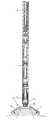
図2は内視鏡用クリップ装置を示しており、1は、例えば四フッ化エチレン樹脂チューブ等のような可撓性チューブからなる可撓性シースであり、図示されていない内視鏡の処置具挿通チャンネル内に挿脱自在である。Embodiments of the present invention will be described below with reference to the drawings.
FIG. 2 shows an endoscopic clip device, and 1 is a flexible sheath made of a flexible tube such as a tetrafluoroethylene resin tube, for example. It can be freely inserted into and removed from the instrument insertion channel.
可撓性シース1の先端には、ばね性のある金属材からなる先端口金2が固定的に取り付けられている。先端口金2は、可撓性シース1の内径と略同じ大きさの内径寸法を有する略円筒形状であり、その最先端部分だけは内径が僅かに小さく形成されている。 A
また先端口金2には、先端側から軸線と平行方向に複数の(例えば、3〜4個の)スリット3が形成されている。その結果、先端口金2の最先端部分付近は押し広げる状態に弾性変形させることができる。 Further, a plurality of (for example, 3 to 4)
可撓性シース1内には、可撓性シース1の基端側に連結された操作部(図示せず)から任意に進退操作することができる操作ワイヤ4が挿通配置されていて、その先端に接続管6を介して連結環5が固着連結されている。 An
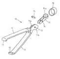
可撓性シース1の先端近傍内には複数のクリップ10が直列に配置されている。クリップ10は、単体の状態とそれを分解して示す図4及び図3に示されるように、個別に独立した部材で形成された一対の開閉アーム11を有していて、各開閉アーム11の先端に形成された先端爪部12は内方に向かってあい対向する状態に曲げられている。 A plurality of
一対の開閉アーム11の後端付近には各々軸孔13が形成されて、そこに支軸14が通され、一対の開閉アーム11が軸孔13を中心に相対的に回動自在に軸孔13により連結された状態になっている。その結果、一対の開閉アーム11が、前方に向かって嘴状に自由に開閉することができる。
15は、操作ワイヤ4との連結を司る環状の連結環15aが後端部に形成された連結用尾部であり、開閉アーム11とは独立した部材として単独で形成されている。なお、連結用尾部15は、操作ワイヤ4に直接連結されるのではなく、後方のクリップ10や後述する連結クリップ20等を介して操作ワイヤ4と連結される。
連結用尾部15には、開閉アーム11の後端部付近を緩く挟み込む形状の一対の平行板部分に、支軸14が通される支持孔16が形成されていて、支軸14により一対の開閉アーム11と回動自在に連結されている。 The connecting
18は、一対の開閉アーム11を強制的に開閉させるための締め環であり、待機状態においては、図4に示されるように開閉アーム11の基部付近に緩く被嵌された状態になっている。
そして、図5に示されるように締め環18を開閉アーム11に対して相対的に後方に移動させると、開閉アーム11の後端に形成された駆動カム11aを締め環18が駆動して、開閉アーム11が一杯に拡開した状態にされる。 Then, as shown in FIG. 5, when the
クリップ10が可撓性シース1の先端から押し出される際には、締め環18の先端面が先端口金2の最先端の窄まり部に当接してその位置で一旦停止するので、このような動作が行われ、さらに強い力でクリップ10が可撓性シース1内から押されると、開閉アーム11が一杯に拡開された状態のまま、締め環18が先端口金2の先端部分を押し広げながら先端口金2の前方に押し出される。 When the
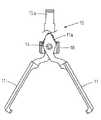
なお、開閉アーム11が締め環18によって一杯に拡開された状態において、締め環18がその位置にある限り開閉アーム11は閉じ方向に動作することができないが、図6に示されるように、一対の開閉アーム11が各々単独で開き方向に動作することはできる。駆動カム11aがその方向に動作する自由空間が締め環18内に形成されているからである。したがって、開閉アーム11が締め環18によって一杯に拡開された状態においても、開閉アーム11は外力によってさらに拡開させることができる。 In the state in which the opening /
図7に示されるように、締め環18が前方に移動すると、その締め環18により開閉アーム11が強制的に閉じた状態にされる。締め環18が先端口金2の前方に押し出された後に連結用尾部15が可撓性シース1内に引き戻されると、締め環18の後端面が先端口金2の外面に当接してこのような動作が行われる。 As shown in FIG. 7, when the
図2に戻って、可撓性シース1の先端近傍内においては、前後に連なって位置する二つのクリップ10,10のうち前側に位置するクリップ10の連結用尾部15と、後側に位置するクリップ10の開閉アーム11とが連結されている。具体的には、前側のクリップ10の後端に位置する連結環15a内に、閉じた状態の後側のクリップ10の開閉アーム11の先端爪部12が差し込まれた状態に係合している。 Returning to FIG. 2, in the vicinity of the distal end of the
20は、連結環5に分離できないように連結された連結クリップであり、締め環18がない以外はクリップ10と同じ構成であって、他のクリップ10と同様にしてその前側に位置するクリップ10と連結されている。このようにして連結された全てのクリップ10,20が、図2に示されるように可撓性シース1内では閉じていて、可撓性シース1がこの状態で内視鏡の処置具挿通チャンネルに挿脱される。
そして、図8に示されるように、クリッピング対象の患部粘膜に向けて可撓性シース1の先端からクリップ10を押し出し、一対の開閉アーム11が締め環18により一杯に拡開された状態にして、それを患部粘膜に押し付ける。 Then, as shown in FIG. 8, the
その際に、患部粘膜の隆起が一対の開閉アーム11の開きより大きい場合等には、図1に示されるように、患部粘膜側から受ける外力によって開閉アーム11がさらに大きく拡開した状態になる。したがって、開閉アーム11が折損することなく、一対の開閉アーム11で患部粘膜を挟み付けた状態にすることができる。 At this time, when the bulge of the affected mucosa is larger than the opening of the pair of opening / closing
そして、操作ワイヤ4を基端側に少し引き戻してクリップ10を締め環18の作用により強制的に閉じてクリッピングを行い、図9に示されるように、先端から二番目のクリップ10を可撓性シース1の先端から押し出して拡開状態にすれば、最先端のクリップ10との連結が解除されて、最先端のクリップ10が体内に留置される。 Then, the
なお、本発明は上記実施例に限定されるものではなく、例えば、本発明をクリップ10が一個だけの単発式の内視鏡用クリップ装置に適用してもよい。 The present invention is not limited to the above-described embodiment. For example, the present invention may be applied to a single-shot endoscope clip device having only one
1 可撓性シース
4 操作ワイヤ
10 クリップ
11 開閉アーム
11a 駆動カム
13 軸孔
14 支軸
15 連結用尾部
18 締め環DESCRIPTION OF
Claims (3)
Translated fromJapanese上記一対の開閉アームを各々個別に独立した部材で形成して支軸を中心に相対的に回動自在に連結し、上記一対の開閉アームが、上記締め環により最も拡開された状態から外力が加わればそれによってさらに拡開されるようにしたことを特徴とする内視鏡用クリップ装置。A clip having a pair of openable and closable arms that can be opened and closed in a hook-like manner toward the front and a fastening ring through which a rear portion of the open / close arm passes is disposed in a state of being constricted in the vicinity of the distal end of the flexible sheath. The clip is pushed forward from the distal end of the flexible sheath with an operation wire disposed in the flexible sheath so as to be movable back and forth in the axial direction, and the positional relationship between the pair of opening and closing arms and the clamp ring is determined. In the endoscope clip device configured to change, the first opening and closing arms are once opened and then closed, and then the connection between the clip and the operation wire can be released.
The pair of open / close arms are individually formed by independent members and are connected so as to be relatively rotatable around a support shaft. The pair of open / close arms is externally applied from a state where the pair of open / close arms are expanded most by the fastening ring. An endoscopic clip device that is further expanded by the addition of.
Priority Applications (3)
| Application Number | Priority Date | Filing Date | Title |
|---|---|---|---|
| JP2007153512AJP2008302097A (en) | 2007-06-11 | 2007-06-11 | Clip device for endoscope |
| US12/131,290US20080306493A1 (en) | 2007-06-11 | 2008-06-02 | Clipping instrument for an endoscopic surgical device |
| DE102008027804ADE102008027804A1 (en) | 2007-06-11 | 2008-06-11 | Stapler for an endoscope |
Applications Claiming Priority (1)
| Application Number | Priority Date | Filing Date | Title |
|---|---|---|---|
| JP2007153512AJP2008302097A (en) | 2007-06-11 | 2007-06-11 | Clip device for endoscope |
Publications (1)
| Publication Number | Publication Date |
|---|---|
| JP2008302097Atrue JP2008302097A (en) | 2008-12-18 |
Family
ID=39986396
Family Applications (1)
| Application Number | Title | Priority Date | Filing Date |
|---|---|---|---|
| JP2007153512APendingJP2008302097A (en) | 2007-06-11 | 2007-06-11 | Clip device for endoscope |
Country Status (3)
| Country | Link |
|---|---|
| US (1) | US20080306493A1 (en) |
| JP (1) | JP2008302097A (en) |
| DE (1) | DE102008027804A1 (en) |
Cited By (1)
| Publication number | Priority date | Publication date | Assignee | Title |
|---|---|---|---|---|
| JP2010246663A (en)* | 2009-04-14 | 2010-11-04 | Hoya Corp | Clip device for endoscope |
Families Citing this family (112)
| Publication number | Priority date | Publication date | Assignee | Title |
|---|---|---|---|---|
| US9763668B2 (en) | 2004-10-08 | 2017-09-19 | Covidien Lp | Endoscopic surgical clip applier |
| EP2641548B1 (en) | 2004-10-08 | 2015-08-19 | Covidien LP | Endoscopic surgical clip applier |
| US8409222B2 (en) | 2004-10-08 | 2013-04-02 | Covidien Lp | Endoscopic surgical clip applier |
| CA2809110A1 (en) | 2004-10-08 | 2006-04-20 | Tyco Healthcare Group Lp | Apparatus for applying surgical clips |
| CA2605135C (en) | 2006-10-17 | 2014-12-30 | Tyco Healthcare Group Lp | Apparatus for applying surgical clips |
| US7655004B2 (en) | 2007-02-15 | 2010-02-02 | Ethicon Endo-Surgery, Inc. | Electroporation ablation apparatus, system, and method |
| EP2157920B1 (en) | 2007-03-26 | 2017-09-27 | Covidien LP | Endoscopic surgical clip applier |
| CN102327136B (en) | 2007-04-11 | 2014-04-23 | 柯惠Lp公司 | Surgical clip applier |
| US8888792B2 (en) | 2008-07-14 | 2014-11-18 | Ethicon Endo-Surgery, Inc. | Tissue apposition clip application devices and methods |
| US8465502B2 (en) | 2008-08-25 | 2013-06-18 | Covidien Lp | Surgical clip applier and method of assembly |
| US20110208212A1 (en) | 2010-02-19 | 2011-08-25 | Zergiebel Earl M | Surgical clip applier |
| US8056565B2 (en) | 2008-08-25 | 2011-11-15 | Tyco Healthcare Group Lp | Surgical clip applier and method of assembly |
| US8267944B2 (en) | 2008-08-29 | 2012-09-18 | Tyco Healthcare Group Lp | Endoscopic surgical clip applier with lock out |
| US8409223B2 (en) | 2008-08-29 | 2013-04-02 | Covidien Lp | Endoscopic surgical clip applier with clip retention |
| US9358015B2 (en) | 2008-08-29 | 2016-06-07 | Covidien Lp | Endoscopic surgical clip applier with wedge plate |
| US8585717B2 (en) | 2008-08-29 | 2013-11-19 | Covidien Lp | Single stroke endoscopic surgical clip applier |
| US8157834B2 (en) | 2008-11-25 | 2012-04-17 | Ethicon Endo-Surgery, Inc. | Rotational coupling device for surgical instrument with flexible actuators |
| US8361066B2 (en) | 2009-01-12 | 2013-01-29 | Ethicon Endo-Surgery, Inc. | Electrical ablation devices |
| US20110098704A1 (en) | 2009-10-28 | 2011-04-28 | Ethicon Endo-Surgery, Inc. | Electrical ablation devices |
| US9186136B2 (en) | 2009-12-09 | 2015-11-17 | Covidien Lp | Surgical clip applier |
| US8545486B2 (en) | 2009-12-15 | 2013-10-01 | Covidien Lp | Surgical clip applier |
| US9028483B2 (en) | 2009-12-18 | 2015-05-12 | Ethicon Endo-Surgery, Inc. | Surgical instrument comprising an electrode |
| US8403945B2 (en) | 2010-02-25 | 2013-03-26 | Covidien Lp | Articulating endoscopic surgical clip applier |
| US8403946B2 (en) | 2010-07-28 | 2013-03-26 | Covidien Lp | Articulating clip applier cartridge |
| US8968337B2 (en) | 2010-07-28 | 2015-03-03 | Covidien Lp | Articulating clip applier |
| US9011464B2 (en) | 2010-11-02 | 2015-04-21 | Covidien Lp | Self-centering clip and jaw |
| US9186153B2 (en) | 2011-01-31 | 2015-11-17 | Covidien Lp | Locking cam driver and jaw assembly for clip applier |
| US9254169B2 (en) | 2011-02-28 | 2016-02-09 | Ethicon Endo-Surgery, Inc. | Electrical ablation devices and methods |
| US9233241B2 (en) | 2011-02-28 | 2016-01-12 | Ethicon Endo-Surgery, Inc. | Electrical ablation devices and methods |
| US9049987B2 (en) | 2011-03-17 | 2015-06-09 | Ethicon Endo-Surgery, Inc. | Hand held surgical device for manipulating an internal magnet assembly within a patient |
| US9775623B2 (en) | 2011-04-29 | 2017-10-03 | Covidien Lp | Surgical clip applier including clip relief feature |
| US20130131697A1 (en) | 2011-11-21 | 2013-05-23 | Covidien Lp | Surgical clip applier |
| US9364239B2 (en) | 2011-12-19 | 2016-06-14 | Covidien Lp | Jaw closure mechanism for a surgical clip applier |
| US9364216B2 (en) | 2011-12-29 | 2016-06-14 | Covidien Lp | Surgical clip applier with integrated clip counter |
| US9408610B2 (en) | 2012-05-04 | 2016-08-09 | Covidien Lp | Surgical clip applier with dissector |
| US9427255B2 (en) | 2012-05-14 | 2016-08-30 | Ethicon Endo-Surgery, Inc. | Apparatus for introducing a steerable camera assembly into a patient |
| US9532787B2 (en) | 2012-05-31 | 2017-01-03 | Covidien Lp | Endoscopic clip applier |
| CN102697564B (en)* | 2012-06-20 | 2014-04-23 | 哈尔滨工业大学 | Flexible-arm robot for minimally invasive single-port abdominal surgery |
| US9078662B2 (en) | 2012-07-03 | 2015-07-14 | Ethicon Endo-Surgery, Inc. | Endoscopic cap electrode and method for using the same |
| US9545290B2 (en) | 2012-07-30 | 2017-01-17 | Ethicon Endo-Surgery, Inc. | Needle probe guide |
| US9572623B2 (en) | 2012-08-02 | 2017-02-21 | Ethicon Endo-Surgery, Inc. | Reusable electrode and disposable sheath |
| US10314649B2 (en) | 2012-08-02 | 2019-06-11 | Ethicon Endo-Surgery, Inc. | Flexible expandable electrode and method of intraluminal delivery of pulsed power |
| US9277957B2 (en) | 2012-08-15 | 2016-03-08 | Ethicon Endo-Surgery, Inc. | Electrosurgical devices and methods |
| US9968362B2 (en) | 2013-01-08 | 2018-05-15 | Covidien Lp | Surgical clip applier |
| US9113892B2 (en) | 2013-01-08 | 2015-08-25 | Covidien Lp | Surgical clip applier |
| US9750500B2 (en) | 2013-01-18 | 2017-09-05 | Covidien Lp | Surgical clip applier |
| US10098527B2 (en) | 2013-02-27 | 2018-10-16 | Ethidcon Endo-Surgery, Inc. | System for performing a minimally invasive surgical procedure |
| US9775624B2 (en) | 2013-08-27 | 2017-10-03 | Covidien Lp | Surgical clip applier |
| US10702278B2 (en) | 2014-12-02 | 2020-07-07 | Covidien Lp | Laparoscopic surgical ligation clip applier |
| US9931124B2 (en) | 2015-01-07 | 2018-04-03 | Covidien Lp | Reposable clip applier |
| CN107205747B (en) | 2015-01-15 | 2020-09-08 | 柯惠有限合伙公司 | Reusable endoscopic surgical clip applier |
| US10292712B2 (en) | 2015-01-28 | 2019-05-21 | Covidien Lp | Surgical clip applier with integrated cutter |
| US10159491B2 (en) | 2015-03-10 | 2018-12-25 | Covidien Lp | Endoscopic reposable surgical clip applier |
| CN108348259B (en) | 2015-11-03 | 2020-12-11 | 柯惠有限合伙公司 | Endoscopic Surgical Fixture Applicator |
| US10702280B2 (en) | 2015-11-10 | 2020-07-07 | Covidien Lp | Endoscopic reposable surgical clip applier |
| US10905425B2 (en) | 2015-11-10 | 2021-02-02 | Covidien Lp | Endoscopic reposable surgical clip applier |
| US10390831B2 (en) | 2015-11-10 | 2019-08-27 | Covidien Lp | Endoscopic reposable surgical clip applier |
| CN108472044B (en) | 2016-01-11 | 2021-04-16 | 柯惠有限合伙公司 | endoscope-reserved surgical clip applier |
| AU2016388454A1 (en) | 2016-01-18 | 2018-07-19 | Covidien Lp | Endoscopic surgical clip applier |
| CA2958160A1 (en) | 2016-02-24 | 2017-08-24 | Covidien Lp | Endoscopic reposable surgical clip applier |
| WO2018027788A1 (en) | 2016-08-11 | 2018-02-15 | Covidien Lp | Endoscopic surgical clip applier and clip applying systems |
| CN109640844B (en) | 2016-08-25 | 2021-08-06 | 柯惠Lp公司 | Endoscopic Surgical Clip Appliers and Applicator Systems |
| US10660651B2 (en) | 2016-10-31 | 2020-05-26 | Covidien Lp | Endoscopic reposable surgical clip applier |
| US10639044B2 (en) | 2016-10-31 | 2020-05-05 | Covidien Lp | Ligation clip module and clip applier |
| US10492795B2 (en) | 2016-11-01 | 2019-12-03 | Covidien Lp | Endoscopic surgical clip applier |
| US10610236B2 (en) | 2016-11-01 | 2020-04-07 | Covidien Lp | Endoscopic reposable surgical clip applier |
| US10426489B2 (en) | 2016-11-01 | 2019-10-01 | Covidien Lp | Endoscopic reposable surgical clip applier |
| US10709455B2 (en) | 2017-02-02 | 2020-07-14 | Covidien Lp | Endoscopic surgical clip applier |
| US11116514B2 (en) | 2017-02-06 | 2021-09-14 | Covidien Lp | Surgical clip applier with user feedback feature |
| US10758244B2 (en) | 2017-02-06 | 2020-09-01 | Covidien Lp | Endoscopic surgical clip applier |
| US10660725B2 (en) | 2017-02-14 | 2020-05-26 | Covidien Lp | Endoscopic surgical clip applier including counter assembly |
| US10603038B2 (en) | 2017-02-22 | 2020-03-31 | Covidien Lp | Surgical clip applier including inserts for jaw assembly |
| US10548602B2 (en) | 2017-02-23 | 2020-02-04 | Covidien Lp | Endoscopic surgical clip applier |
| US11583291B2 (en) | 2017-02-23 | 2023-02-21 | Covidien Lp | Endoscopic surgical clip applier |
| US10675043B2 (en) | 2017-05-04 | 2020-06-09 | Covidien Lp | Reposable multi-fire surgical clip applier |
| US10722235B2 (en) | 2017-05-11 | 2020-07-28 | Covidien Lp | Spring-release surgical clip |
| US10660723B2 (en) | 2017-06-30 | 2020-05-26 | Covidien Lp | Endoscopic reposable surgical clip applier |
| US10639032B2 (en) | 2017-06-30 | 2020-05-05 | Covidien Lp | Endoscopic surgical clip applier including counter assembly |
| US10675112B2 (en) | 2017-08-07 | 2020-06-09 | Covidien Lp | Endoscopic surgical clip applier including counter assembly |
| US10932790B2 (en) | 2017-08-08 | 2021-03-02 | Covidien Lp | Geared actuation mechanism and surgical clip applier including the same |
| US10863992B2 (en) | 2017-08-08 | 2020-12-15 | Covidien Lp | Endoscopic surgical clip applier |
| US10786262B2 (en) | 2017-08-09 | 2020-09-29 | Covidien Lp | Endoscopic reposable surgical clip applier |
| US10786263B2 (en) | 2017-08-15 | 2020-09-29 | Covidien Lp | Endoscopic reposable surgical clip applier |
| US10835341B2 (en) | 2017-09-12 | 2020-11-17 | Covidien Lp | Endoscopic surgical clip applier and handle assemblies for use therewith |
| US10835260B2 (en) | 2017-09-13 | 2020-11-17 | Covidien Lp | Endoscopic surgical clip applier and handle assemblies for use therewith |
| US10653429B2 (en) | 2017-09-13 | 2020-05-19 | Covidien Lp | Endoscopic surgical clip applier |
| US10758245B2 (en) | 2017-09-13 | 2020-09-01 | Covidien Lp | Clip counting mechanism for surgical clip applier |
| US10932791B2 (en) | 2017-11-03 | 2021-03-02 | Covidien Lp | Reposable multi-fire surgical clip applier |
| US10828036B2 (en) | 2017-11-03 | 2020-11-10 | Covidien Lp | Endoscopic surgical clip applier and handle assemblies for use therewith |
| US11116513B2 (en) | 2017-11-03 | 2021-09-14 | Covidien Lp | Modular surgical clip cartridge |
| US11376015B2 (en) | 2017-11-03 | 2022-07-05 | Covidien Lp | Endoscopic surgical clip applier and handle assemblies for use therewith |
| US10945734B2 (en) | 2017-11-03 | 2021-03-16 | Covidien Lp | Rotation knob assemblies and surgical instruments including the same |
| US10722236B2 (en) | 2017-12-12 | 2020-07-28 | Covidien Lp | Endoscopic reposable surgical clip applier |
| US10849630B2 (en) | 2017-12-13 | 2020-12-01 | Covidien Lp | Reposable multi-fire surgical clip applier |
| US10959737B2 (en) | 2017-12-13 | 2021-03-30 | Covidien Lp | Reposable multi-fire surgical clip applier |
| US10743887B2 (en) | 2017-12-13 | 2020-08-18 | Covidien Lp | Reposable multi-fire surgical clip applier |
| US11051827B2 (en) | 2018-01-16 | 2021-07-06 | Covidien Lp | Endoscopic surgical instrument and handle assemblies for use therewith |
| CN108554183B (en)* | 2018-04-09 | 2023-06-27 | 北京天地人环保科技有限公司 | Membrane shell disassembling tool for disc tube type membrane column |
| US10993721B2 (en) | 2018-04-25 | 2021-05-04 | Covidien Lp | Surgical clip applier |
| US10786273B2 (en) | 2018-07-13 | 2020-09-29 | Covidien Lp | Rotation knob assemblies for handle assemblies |
| US11344316B2 (en) | 2018-08-13 | 2022-05-31 | Covidien Lp | Elongated assemblies for surgical clip appliers and surgical clip appliers incorporating the same |
| US11246601B2 (en) | 2018-08-13 | 2022-02-15 | Covidien Lp | Elongated assemblies for surgical clip appliers and surgical clip appliers incorporating the same |
| US11051828B2 (en) | 2018-08-13 | 2021-07-06 | Covidien Lp | Rotation knob assemblies and surgical instruments including same |
| US11219463B2 (en) | 2018-08-13 | 2022-01-11 | Covidien Lp | Bilateral spring for surgical instruments and surgical instruments including the same |
| US11278267B2 (en) | 2018-08-13 | 2022-03-22 | Covidien Lp | Latch assemblies and surgical instruments including the same |
| US11147566B2 (en) | 2018-10-01 | 2021-10-19 | Covidien Lp | Endoscopic surgical clip applier |
| US11524398B2 (en) | 2019-03-19 | 2022-12-13 | Covidien Lp | Gear drive mechanisms for surgical instruments |
| CN112704535B (en)* | 2019-10-25 | 2022-11-25 | 苏州英途康医疗科技有限公司 | Clamping device and surgical operation instrument |
| US11779340B2 (en) | 2020-01-02 | 2023-10-10 | Covidien Lp | Ligation clip loading device |
| US11723669B2 (en) | 2020-01-08 | 2023-08-15 | Covidien Lp | Clip applier with clip cartridge interface |
| US12114866B2 (en) | 2020-03-26 | 2024-10-15 | Covidien Lp | Interoperative clip loading device |
| US12419648B2 (en) | 2022-09-26 | 2025-09-23 | Covidien Lp | Two-part fasteners for surgical clip appliers and surgical clip appliers for deploying the same |
Family Cites Families (8)
| Publication number | Priority date | Publication date | Assignee | Title |
|---|---|---|---|---|
| JP2001327512A (en)* | 2000-05-24 | 2001-11-27 | Asahi Optical Co Ltd | Endoscope treatment tool |
| JP4472217B2 (en)* | 2000-10-16 | 2010-06-02 | オリンパス株式会社 | Biological tissue clip device |
| JP4827304B2 (en)* | 2001-03-14 | 2011-11-30 | オリンパス株式会社 | Biological tissue clip device |
| US6991634B2 (en)* | 2001-05-23 | 2006-01-31 | Pentax Corporation | Clip device of endoscope |
| JP3869698B2 (en)* | 2001-10-23 | 2007-01-17 | ペンタックス株式会社 | Electronic endoscope device |
| JP2003265411A (en)* | 2002-03-20 | 2003-09-24 | Pentax Corp | Electronic endoscope apparatus, electronic endoscope, and video signal processing apparatus |
| JP4261450B2 (en) | 2004-09-22 | 2009-04-30 | Hoya株式会社 | Endoscopic clip device |
| US20070100205A1 (en)* | 2005-10-27 | 2007-05-03 | Pentax Corporation | Image capturing system for electronic endoscope system |
- 2007
- 2007-06-11JPJP2007153512Apatent/JP2008302097A/enactivePending
- 2008
- 2008-06-02USUS12/131,290patent/US20080306493A1/ennot_activeAbandoned
- 2008-06-11DEDE102008027804Apatent/DE102008027804A1/ennot_activeWithdrawn
Cited By (1)
| Publication number | Priority date | Publication date | Assignee | Title |
|---|---|---|---|---|
| JP2010246663A (en)* | 2009-04-14 | 2010-11-04 | Hoya Corp | Clip device for endoscope |
Also Published As
| Publication number | Publication date |
|---|---|
| DE102008027804A1 (en) | 2008-12-18 |
| US20080306493A1 (en) | 2008-12-11 |
Similar Documents
| Publication | Publication Date | Title |
|---|---|---|
| JP2008302097A (en) | Clip device for endoscope | |
| JP5006753B2 (en) | Endoscopic clip device | |
| JP2008307168A (en) | Clip device for endoscope | |
| JP4598181B2 (en) | Endoscopic clip device | |
| JP4145149B2 (en) | Biological tissue clip device | |
| JP4360383B2 (en) | Clip device | |
| JP6084346B1 (en) | Clip device | |
| WO2016190190A1 (en) | Device for endoscope | |
| JP5246394B2 (en) | Clip, clip unit and clip device | |
| JP2000287981A (en) | Indwelling clip in cavity in living body | |
| JP2003144444A (en) | Endoscope clip device | |
| JP2007275518A (en) | Clip for endoscope | |
| JP4491589B2 (en) | Endoscopic clip device | |
| JP4105406B2 (en) | Endoscopic clip device | |
| JP3917466B2 (en) | Endoscopic clip device | |
| JP4575763B2 (en) | Endoscopic clip device | |
| JP2005058627A (en) | Endoscopic clip device | |
| JP4981536B2 (en) | Endoscopic clip device | |
| JP5258663B2 (en) | Endoscopic clip device | |
| JP4037072B2 (en) | Endoscopic clip device | |
| JP3917465B2 (en) | Endoscopic clip device | |
| JP4412943B2 (en) | Endoscopic clip device | |
| JP4338457B2 (en) | Endoscopic clip device | |
| JP3914462B2 (en) | Endoscopic clip device | |
| JP4512725B2 (en) | Endoscopic clip device |