JP2008302045A - Clip device for endoscope - Google Patents
Clip device for endoscopeDownload PDFInfo
- Publication number
- JP2008302045A JP2008302045AJP2007152343AJP2007152343AJP2008302045AJP 2008302045 AJP2008302045 AJP 2008302045AJP 2007152343 AJP2007152343 AJP 2007152343AJP 2007152343 AJP2007152343 AJP 2007152343AJP 2008302045 AJP2008302045 AJP 2008302045A
- Authority
- JP
- Japan
- Prior art keywords
- flexible sheath
- clip
- annular member
- operation wire
- endoscope
- Prior art date
- Legal status (The legal status is an assumption and is not a legal conclusion. Google has not performed a legal analysis and makes no representation as to the accuracy of the status listed.)
- Pending
Links
- 238000003780insertionMethods0.000claimsdescription11
- 230000037431insertionEffects0.000claimsdescription11
- 230000002093peripheral effectEffects0.000claimsdescription9
- 238000013459approachMethods0.000claimsdescription4
- 230000000007visual effectEffects0.000abstract1
- 230000000694effectsEffects0.000description3
- 210000000078clawAnatomy0.000description2
- 229910001220stainless steelInorganic materials0.000description2
- 230000008878couplingEffects0.000description1
- 238000010168coupling processMethods0.000description1
- 238000005859coupling reactionMethods0.000description1
- 239000007769metal materialSubstances0.000description1
- 238000000034methodMethods0.000description1
- 239000011347resinSubstances0.000description1
- 229920005989resinPolymers0.000description1
- 239000010935stainless steelSubstances0.000description1
- BFKJFAAPBSQJPD-UHFFFAOYSA-NtetrafluoroetheneChemical groupFC(F)=C(F)FBFKJFAAPBSQJPD-UHFFFAOYSA-N0.000description1
Images


Classifications
- A—HUMAN NECESSITIES
- A61—MEDICAL OR VETERINARY SCIENCE; HYGIENE
- A61B—DIAGNOSIS; SURGERY; IDENTIFICATION
- A61B17/00—Surgical instruments, devices or methods
- A61B17/12—Surgical instruments, devices or methods for ligaturing or otherwise compressing tubular parts of the body, e.g. blood vessels or umbilical cord
- A61B17/128—Surgical instruments, devices or methods for ligaturing or otherwise compressing tubular parts of the body, e.g. blood vessels or umbilical cord for applying or removing clamps or clips
- A61B17/1285—Surgical instruments, devices or methods for ligaturing or otherwise compressing tubular parts of the body, e.g. blood vessels or umbilical cord for applying or removing clamps or clips for minimally invasive surgery
- A—HUMAN NECESSITIES
- A61—MEDICAL OR VETERINARY SCIENCE; HYGIENE
- A61B—DIAGNOSIS; SURGERY; IDENTIFICATION
- A61B17/00—Surgical instruments, devices or methods
- A61B17/00234—Surgical instruments, devices or methods for minimally invasive surgery
- A61B2017/00292—Surgical instruments, devices or methods for minimally invasive surgery mounted on or guided by flexible, e.g. catheter-like, means
- A61B2017/0034—Surgical instruments, devices or methods for minimally invasive surgery mounted on or guided by flexible, e.g. catheter-like, means adapted to be inserted through a working channel of an endoscope
Landscapes
- Health & Medical Sciences (AREA)
- Surgery (AREA)
- Life Sciences & Earth Sciences (AREA)
- Heart & Thoracic Surgery (AREA)
- Molecular Biology (AREA)
- Vascular Medicine (AREA)
- Engineering & Computer Science (AREA)
- Biomedical Technology (AREA)
- Reproductive Health (AREA)
- Medical Informatics (AREA)
- Nuclear Medicine, Radiotherapy & Molecular Imaging (AREA)
- Animal Behavior & Ethology (AREA)
- General Health & Medical Sciences (AREA)
- Public Health (AREA)
- Veterinary Medicine (AREA)
- Surgical Instruments (AREA)
- Endoscopes (AREA)
Abstract
Description
Translated fromJapaneseこの発明は内視鏡用クリップ装置に関する。 The present invention relates to an endoscope clip device.
内視鏡用クリップ装置(特に、複数のクリップが分離可能に直列に配置されたいわゆる連発クリップ装置)においては一般に、内視鏡の処置具挿通チャンネルに挿脱される可撓性シース内に軸線方向に進退自在に挿通配置された操作ワイヤを基端側から先端側に押し込み操作することにより、操作ワイヤの先端に分離可能に連結されたクリップが可撓性シースの先端内から前方に押し出されて拡開し、さらに操作ワイヤを進退操作することにより、クリップが閉じてからクリップと操作ワイヤを分離することができるように構成されている(例えば、特許文献1)。
上述したような従来の内視鏡用クリップ装置は、操作ワイヤが押し込み操作されてクリップの先端が可撓性シースの先端にさしかかった後、クリップが開閉したり前後に進退する動作を内視鏡の観察画面で視認しながら使用するようになっている。 The conventional endoscope clip device as described above has an operation in which the clip opens and closes and moves back and forth after the operation wire is pushed in and the tip of the clip reaches the tip of the flexible sheath. It is designed to be used while viewing on the observation screen.
しかし、内視鏡の観察画像においては、突出するクリップをその背後から見た状態になるので、クリップが一杯に拡開した状態になっているのか、或いはクリップが可撓性シースの先端からどの程度突出した状態なのか等の正確な把握が困難であり、特に内視鏡の観察視界が鮮明でない条件下等においては誤操作をするおそれがあった。 However, in the observation image of the endoscope, the protruding clip is viewed from behind, so that the clip is fully expanded, or which clip is from the distal end of the flexible sheath. It is difficult to accurately grasp whether it is in a protruding state or the like, and there is a risk of erroneous operation particularly under conditions where the observation field of view of the endoscope is not clear.
本発明は、内視鏡の観察視界が鮮明でない場合等であっても、操作者がクリップの拡開状態や可撓性シースからの突出状態を正確に把握してスムーズに操作することができる内視鏡用クリップ装置を提供することを目的とする。 According to the present invention, even when the observation field of view of the endoscope is not clear, the operator can accurately grasp the expanded state of the clip and the protruding state from the flexible sheath and operate it smoothly. An object of the present invention is to provide an endoscopic clip device.
上記の目的を達成するため、本発明の内視鏡用クリップ装置は、内視鏡の処置具挿通チャンネルに挿脱される可撓性シース内に軸線方向に進退自在に挿通配置された操作ワイヤを基端側から先端側に押し込み操作することにより、操作ワイヤの先端に分離可能に連結されたクリップが、可撓性シースの先端内から前方に押し出されて拡開し、さらに操作ワイヤを進退操作することにより、クリップが閉じてからクリップと操作ワイヤを分離することができるように構成された内視鏡用クリップ装置において、可撓性シースの途中の部分とそこを通過する操作ワイヤの途中の部分とに、操作ワイヤが押し込み操作されてクリップの先端が可撓性シースの先端にさしかかった時からクリップが一杯に拡開する状態になるまでの間摩擦抵抗を発生して、クリップが一杯に拡開した直後の状態では摩擦抵抗を発生しない摩擦抵抗発生手段を設けたものである。 In order to achieve the above object, an endoscope clip device of the present invention is an operation wire that is inserted and arranged in a flexible sheath that is inserted into and removed from a treatment instrument insertion channel of an endoscope so as to be capable of moving forward and backward in the axial direction. When the clip is squeezed from the proximal end side to the distal end side, the clip detachably connected to the distal end of the operation wire is pushed forward from the distal end of the flexible sheath to expand, and the operation wire is further advanced and retracted. In an endoscope clip device configured to be able to separate a clip and an operation wire after the clip is closed by an operation, an intermediate portion of the flexible sheath and an intermediate portion of the operation wire passing therethrough A frictional resistance is generated between the point when the operation wire is pushed into the portion of the wire and the tip of the clip reaches the tip of the flexible sheath until the clip fully expands. , In the state immediately after the clip has been expanded to fill it is provided with a frictional resistance generating means generating no frictional resistance.
なお、摩擦抵抗発生手段が、可撓性シースの内周部に固定された環状部材と、操作ワイヤを囲む状態に操作ワイヤに固定された筒状部材とを備えていて、環状部材と筒状部材の少なくとも一方がばね性を有し、環状部材は内径が可撓性シースの内周より小さく形成されて、筒状部材は外径が可撓性シースの内周より小さく且つ環状部材の内径より大きく形成され、筒状部材が環状部材内を通過する際に筒状部材と環状部材のうちばね性を有する側が弾性変形して摩擦抵抗が発生するようにしてもよい。 The frictional resistance generating means includes an annular member fixed to the inner peripheral portion of the flexible sheath, and a cylindrical member fixed to the operation wire so as to surround the operation wire. At least one of the members has a spring property, the annular member has an inner diameter smaller than the inner circumference of the flexible sheath, and the cylindrical member has an outer diameter smaller than the inner circumference of the flexible sheath and the inner diameter of the annular member. It may be formed larger, and when the tubular member passes through the annular member, the side having the spring property of the tubular member and the annular member may be elastically deformed to generate a frictional resistance.
また、環状部材が、可撓性シースの内周部に圧入固定されていてもよく、或いは、可撓性シースの軸線方向に互いの間隔をあけて可撓性シースの内周部に圧入固定された一対の抜け止め部材の間に挟持されていてもよい。 Further, the annular member may be press-fitted and fixed to the inner peripheral portion of the flexible sheath, or press-fitted and fixed to the inner peripheral portion of the flexible sheath with an interval between each other in the axial direction of the flexible sheath. It may be sandwiched between a pair of retaining members.
また、環状部材が、同じ径で複数回巻かれたばね性のあるコイル或いはばね性のあるCリングであってもよく、可撓性シース自体を部分的に小さな径に塑性変形させて形成されていてもよい。また、筒状部材が円筒状のパイプであってもよい。 Further, the annular member may be a springy coil or a springy C-ring wound with the same diameter a plurality of times, and is formed by plastic deformation of the flexible sheath itself to a small diameter. May be. Further, the cylindrical member may be a cylindrical pipe.
また、クリップとして、互いに分離可能な複数のクリップが操作ワイヤの先端に直列に連結されていて、環状部材と筒状部材の一方が複数のクリップの連結ピッチに対応するピッチで複数配置されていてもよい。 Also, as the clip, a plurality of clips that can be separated from each other are connected in series to the tip of the operation wire, and one of the annular member and the cylindrical member is arranged at a pitch corresponding to the connection pitch of the plurality of clips. Also good.
本発明によれば、可撓性シースの途中の部分とそこを通過する操作ワイヤの途中の部分とに、操作ワイヤが押し込み操作されてクリップの先端が可撓性シースの先端にさしかかった時からクリップが一杯に拡開する状態になるまでの間摩擦抵抗を発生して、クリップが一杯に拡開した直後の状態では摩擦抵抗を発生しない摩擦抵抗発生手段を設けたことにより、内視鏡の観察視界が鮮明でない場合等であっても、操作者がクリップの拡開状態や可撓性シースからの突出状態を手元の感覚により正確に把握してスムーズに操作することができる。 According to the present invention, since the operation wire is pushed into the middle portion of the flexible sheath and the middle portion of the operation wire passing therethrough, the tip of the clip approaches the tip of the flexible sheath. By providing friction resistance generating means that generates frictional resistance until the clip is fully expanded and does not generate frictional resistance immediately after the clip is fully expanded, Even when the observation field of view is not clear, the operator can accurately grasp the spread state of the clip and the protruding state from the flexible sheath with a sense of hand and perform a smooth operation.
内視鏡の処置具挿通チャンネルに挿脱される可撓性シース内に軸線方向に進退自在に挿通配置された操作ワイヤを基端側から先端側に押し込み操作することにより、操作ワイヤの先端に分離可能に連結されたクリップが、可撓性シースの先端内から前方に押し出されて拡開し、さらに操作ワイヤを進退操作することにより、クリップが閉じてからクリップと操作ワイヤを分離することができるように構成された内視鏡用クリップ装置において、可撓性シースの途中の部分とそこを通過する操作ワイヤの途中の部分とに、操作ワイヤが押し込み操作されてクリップの先端が可撓性シースの先端にさしかかった時からクリップが一杯に拡開する状態になるまでの間摩擦抵抗を発生して、クリップが一杯に拡開した直後の状態では摩擦抵抗を発生しない摩擦抵抗発生手段を設ける。 By pushing the operation wire, which is inserted through the flexible sheath inserted into and removed from the treatment instrument insertion channel of the endoscope, so as to be able to advance and retract in the axial direction from the proximal end side to the distal end side, The clip that is separably connected is pushed forward from the distal end of the flexible sheath to expand, and the operation wire is further advanced and retracted to separate the clip and the operation wire after the clip is closed. In an endoscopic clip device configured to be able to perform the operation, the operation wire is pushed into the middle portion of the flexible sheath and the middle portion of the operation wire passing therethrough so that the tip of the clip is flexible. Friction resistance is generated from when the tip of the sheath is approached until the clip is fully expanded, and immediately after the clip is fully expanded, friction resistance is generated. Providing a frictional resistance generating means have.
以下、図面を参照して本発明の実施例を説明する。
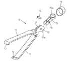
図1は本発明の第1の実施例の内視鏡用クリップ装置を示しており、1は、例えば四フッ化エチレン樹脂チューブ等のような可撓性チューブからなる可撓性シースであり、図示されていない内視鏡の処置具挿通チャンネル内に挿脱自在である。Embodiments of the present invention will be described below with reference to the drawings.
FIG. 1 shows an endoscopic clip device according to a first embodiment of the present invention, wherein 1 is a flexible sheath made of a flexible tube such as a tetrafluoroethylene resin tube, for example. It can be inserted into and removed from a treatment instrument insertion channel of an endoscope (not shown).
可撓性シース1の先端に取り付けられた先端口金2内には、ばね性のある金属材からなるCリング3が配置されている。Cリング3は、軸線方向への移動は阻止されているが、先端口金2内で押し広げる状態に弾性変形させることができる。 A C-
可撓性シース1内には、可撓性シース1の基端側に連結された操作部(図示せず)から任意に進退操作することができる操作ワイヤ4が挿通配置されていて、その先端に接続管6を介して連結環5が固着連結されている。 An
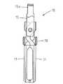
可撓性シース1の先端近傍内には複数のクリップ10が直列に配置されている。クリップ10は、単体の状態とそれを分解して示す図3及び図2に示されるように、個別に独立して形成された一対の開閉アーム11を有していて、各開閉アーム11の先端に形成された先端爪部12は内方に向かってあい対向する状態に曲げられている。 A plurality of
一対の開閉アーム11の後端付近には各々軸孔13が形成されていて、そこに通された支軸14を中心にして、一対の開閉アーム11が前方に向かって嘴状に自由に開閉することができる。
15は、操作ワイヤ4との連結を司る環状の連結環15aが後端部に形成された連結用尾部であり、開閉アーム11の後端部付近を緩く挟み込む形状の一対の平行板部分に、支軸14が通される支持孔16が形成されている。なお、連結用尾部15は、操作ワイヤ4に直接連結されるのではなく、後方のクリップ10や後述する連結用クリップ20等を介して操作ワイヤ4と連結される。 15 is a connection tail portion formed at the rear end portion of an
18は、一対の開閉アーム11を強制的に開閉させるための締め環であり、待機状態においては、図3に示されるように開閉アーム11の基部付近に緩く被嵌された状態になっている。
そして、図4に示されるように締め環18を開閉アーム11に対して相対的に後方に移動させると、開閉アーム11の後端に形成された駆動カム11aに締め環18がぶつかって、開閉アーム11が開いた状態にされる。 Then, as shown in FIG. 4, when the
クリップ10が可撓性シース1の先端から押し出される際には、締め環18の先端面が一旦Cリング3に当接してその位置で停止するので、このような動作が行われ、さらに強い力でクリップ10が可撓性シース1内から押されると、開閉アーム11が一杯に開いた状態のまま、締め環18がCリング3を押し広げながら先端口金2の前方に押し出される。 When the
逆に、図5に示されるように締め環18が前方に移動すると、開閉アーム11が強制的に閉じた状態にされる。締め環18が先端口金2の前方に押し出された後に連結用尾部15が可撓性シース1内に引き戻されると、締め環18の後端面がCリング3に当接してこのような動作が行われる。 Conversely, as shown in FIG. 5, when the
図1に戻って、可撓性シース1の先端近傍内においては、前後に連なって位置する二つのクリップ10,10のうち前側に位置するクリップ10の連結用尾部15と、後側に位置するクリップ10の開閉アーム11とが連結されている。具体的には、前側のクリップ10の後端に位置する連結環15a内に、閉じた状態の後側のクリップ10の開閉アーム11の先端爪部12が差し込まれた状態に係合している。 Returning to FIG. 1, in the vicinity of the distal end of the
20は、クリップ10と同じ構成であって連結環5に分離できないように連結された連結用クリップであり、他のクリップ10と同様にしてその前側に位置するクリップ10と連結されている。このようにして連結された全てのクリップ10,20が可撓性シース1内では閉じていて、可撓性シース1がこの状態で内視鏡の処置具挿通チャンネルに挿脱される。
可撓性シース1の途中の部分とそこを通過する操作ワイヤ4の途中の部分とには、可撓性シース1内における操作ワイヤ4の進退動作に対して摩擦抵抗を付与するための摩擦抵抗発生手段31,32が設けられている。 Friction resistance for imparting friction resistance to the forward / backward movement of the
摩擦抵抗発生手段31,32が設けられる位置は、可撓性シース1が内視鏡の処置具挿通チャンネルに通された使用状態において、内視鏡挿入部の先端近傍に遠隔操作により屈曲するように設けられている湾曲部より少し後方位置辺りにするのが好ましい。 The position where the frictional resistance generating means 31 and 32 are provided is such that the
図6に拡大図示されるように、摩擦抵抗発生手段31,32は、可撓性シース1の内周部に圧入固定された環状部材31と、操作ワイヤ4を囲む状態に操作ワイヤ4に固定された筒状部材32からなり、この実施例においては、環状部材31は、例えばばね用ステンレス鋼線を一定の径で複数回巻いたばね性を有するコイルで形成され、筒状部材32は、例えば複数の円筒状のステンレス鋼パイプが間隔をあけて用いられている。 As shown in an enlarged view in FIG. 6, the frictional resistance generating means 31 and 32 are fixed to the
環状部材31は、内径が可撓性シース1の内周より小さく、且つ外径が可撓性シース1の内周より僅かに大きく形成されている。一方、筒状部材32は外径が可撓性シース1の内周より小さく且つ環状部材31の内径より僅かに大きく(例えば、直径で0.05〜0.1mm程度大きく)形成されている。 The
その結果、筒状部材32が環状部材31内を通過する際にばね性を有する環状部材31側が押し広げられた状態に弾性変形することにより、環状部材31と筒状部材32との間に一定の摩擦抵抗が発生し、筒状部材32が環状部材31内に位置していない状態の時は摩擦抵抗が発生しない。 As a result, when the
図1に示されるように、筒状部材32は、先端において連結されている複数のクリップ10,20の数と同数が、各クリップ10,20の連結ピッチ間隔と同じピッチ間隔で操作ワイヤ4に固着されている。 As shown in FIG. 1, the
そして、各筒状部材32の長さと固着位置は、操作ワイヤ4が基端側(図において上方)から押し込み操作されて最先端のクリップ10の先端が可撓性シース1の先端(厳密には先端口金2の先端)にさしかかった時からクリップ10が一杯に拡開する状態になるまでの間は環状部材31との間で摩擦抵抗が発生し、クリップ10が一杯に拡開した直後の位置では筒状部材32が環状部材31内を通過し終わって摩擦抵抗が発生しなくなるように設定されている。 The length and fixing position of each
そのような内視鏡用クリップ装置が内視鏡の処置具挿通チャンネルに通された使用状態において、操作ワイヤ4が基端側から進退操作された場合の状態変化を、図1及び図7〜図10を参照して順に説明する。 FIG. 1 and FIG. 7 to FIG. 7 show changes in the state when the
可撓性シース1が内視鏡の処置具挿通チャンネルに通される際には、図1に示されるように、最先端のクリップ10の先端が可撓性シース1の先端(即ち、先端口金2の先端)から突出する寸前の位置にあり、その時、最先端の筒状部材32が環状部材31の後端に当接する状態にある。したがって、その当接抵抗が手元側で操作者に感じられ、クリップ10の先端が可撓性シース1の先端から突出する寸前の位置にあることが手の感触で把握される。 When the
そして、可撓性シース1が処置具挿通チャンネルに通されてクリッピング対象の患部に接近したら、図7に示されるように、操作ワイヤ4を基端側から押し込み操作することにより、最先端のクリップ10が可撓性シース1の先端から前方に突出して次第に開きはじめ、その間、最先端の筒状部材32が環状部材31中を通過中の状態になるので、それによる摩擦抵抗が手元側の操作者に感じられ、クリップ10がまだ一杯に拡開していないことが手の感触で把握される。 Then, when the
次いで、図8に示されるように、締め環18がCリング3を通過する状態まで最先端のクリップ10が前方に押し出されると、そのクリップ10が締め環18により一杯に拡開された状態になり、それと同時に最先端の筒状部材32が環状部材31を通過し終わった状態になる。したがって、摩擦抵抗発生手段31,32による摩擦抵抗が急になくなってそれが手元側の操作者に感じられ、最先端のクリップ10が一杯に拡開したことが手の感触で把握される。 Next, as shown in FIG. 8, when the most
そこで、可撓性シース1を前方に押し進める操作をして最先端のクリップ10の一対の開閉アーム11で患部を挟み付けた後、図9に示されるように操作ワイヤ4を基端側に牽引する操作を行うと、後方に少し引き戻された最先端のクリップ10が閉じて患部にクリッピングされた状態になる。この時、最先端の筒状部材32が環状部材31内に再び入り込んでその摩擦抵抗が手元側の操作者に感じられ、最先端のクリップ10が閉じたことが手の感触で把握される。 Then, after pushing the
そのようにして患部に対するクリッピングが行われたら、図10に示されるように操作ワイヤ4を再び基端側から押し込み操作すると、最先端のクリップ10が閉じて患部をクリッピングした状態のまま可撓性シース1内から前方に押し出される。この時、最先端の筒状部材32は環状部材31から前方に抜け出して手元側の操作者には摩擦抵抗のない状態が感じられる。 When clipping is performed on the affected area in this way, if the
そして、先端から二番目のクリップ10の先端が可撓性シース1の先端から突出する寸前の位置に差しかかると、二番目の筒状部材32が環状部材31の後端に当接する。したがって、その当接抵抗が手元側で操作者に感じられ、二番目のクリップ10の先端が可撓性シース1の先端から突出する寸前の位置にあることが手の感触で把握される。 Then, when the tip of the
そこで、図11に示されるように、さらに操作ワイヤ4を基端側から押し込み操作することにより、二番目のクリップ10が開いて最先端のクリップ10との連結が解除され、最先端のクリップ10が体内に留置された状態になる。 Therefore, as shown in FIG. 11, by further pushing the
続いて、必要に応じて二番目のクリップ10により上述と同様の手順でクリッピングを行うことができ、このような一連の動作の状態を、操作者が手の感覚で確実に把握することができる。 Subsequently, if necessary, the
図12は、本発明の第2の実施例の摩擦抵抗発生手段31,32を示しており、ばね性のある円形リングの一か所が切断されたCリングにより環状部材31が形成されている。その環状部材31は可撓性シース1内に緩く配置されており、軸線方向に互いの間隔をあけて可撓性シース1の内周部に圧入固定された一対のコイル等からなる抜け止め部材33の間に挟持されて、可撓性シース1内で移動しないようになっている。このようにしても、第1の実施例と同様の作用効果を得ることができる。 FIG. 12 shows frictional resistance generating means 31 and 32 according to the second embodiment of the present invention, and an
図13は本発明の第3の実施例の摩擦抵抗発生手段31,32を示しており、操作ワイヤ4に固定された筒状部材32を一個だけにして、可撓性シース1の内周部に固定された環状部材31をクリップ10の数に対応する数だけクリップ10の連結ピッチ間隔と同じピッチ間隔で設けたものである。このようにしても、第1の実施例と同様の作用効果を得ることができる。 FIG. 13 shows frictional resistance generating means 31 and 32 according to the third embodiment of the present invention, and only one
図14は本発明の第4の実施例の摩擦抵抗発生手段31,32を示しており、環状部材31として特別の部材を設けずに、可撓性シース1自体を部分的に小さな径に塑性変形させて環状部材31を形成したものである。このようにしても、第1の実施例と同様の作用効果を得ることができる。 FIG. 14 shows frictional resistance generating means 31 and 32 according to the fourth embodiment of the present invention, and without providing a special member as the
なお、本発明は上記各実施例に限定されるものではなく、例えば、本発明をクリップ10が一個だけの単発式の内視鏡用クリップ装置に適用してもよい。 The present invention is not limited to the above-described embodiments. For example, the present invention may be applied to a single-shot endoscope clip apparatus having only one
1 可撓性シース
2 先端口金
3 Cリング
4 操作ワイヤ
10 クリップ
11 開閉アーム
18 締め環
20 連結用クリップ
31 環状部材(摩擦抵抗発生手段)
32 筒状部材(摩擦抵抗発生手段)
33 抜け止め部材DESCRIPTION OF
32 Cylindrical member (Friction resistance generating means)
33 Retaining member
Claims (10)
Translated fromJapanese上記可撓性シースの途中の部分とそこを通過する上記操作ワイヤの途中の部分とに、上記操作ワイヤが押し込み操作されて上記クリップの先端が上記可撓性シースの先端にさしかかった時から上記クリップが一杯に拡開する状態になるまでの間摩擦抵抗を発生して、上記クリップが一杯に拡開した直後の状態では摩擦抵抗を発生しない摩擦抵抗発生手段を設けたことを特徴とする内視鏡用クリップ装置。The distal end of the operation wire is pushed by pushing from the proximal end side to the distal end side an operation wire that is inserted and removed in a flexible sheath that is inserted into and removed from the treatment instrument insertion channel of the endoscope. The clip detachably coupled to the flexible sheath is pushed forward from the distal end of the flexible sheath to expand, and the operation wire is further advanced and retracted to close the clip and the operation. In an endoscopic clip device configured to be able to separate wires,
The operation wire is pushed into the middle portion of the flexible sheath and the middle portion of the operation wire passing through the flexible sheath, and the tip of the clip approaches the tip of the flexible sheath. Friction resistance generating means is provided that generates frictional resistance until the clip is fully expanded, and does not generate frictional resistance immediately after the clip is fully expanded. Endoscopic clip device.
Priority Applications (3)
| Application Number | Priority Date | Filing Date | Title |
|---|---|---|---|
| JP2007152343AJP2008302045A (en) | 2007-06-08 | 2007-06-08 | Clip device for endoscope |
| US12/123,694US20080306492A1 (en) | 2007-06-08 | 2008-05-20 | Clipping instrument for an endoscopic surgical device |
| DE102008027455ADE102008027455A1 (en) | 2007-06-08 | 2008-06-09 | Stapler for an endoscope |
Applications Claiming Priority (1)
| Application Number | Priority Date | Filing Date | Title |
|---|---|---|---|
| JP2007152343AJP2008302045A (en) | 2007-06-08 | 2007-06-08 | Clip device for endoscope |
Publications (1)
| Publication Number | Publication Date |
|---|---|
| JP2008302045Atrue JP2008302045A (en) | 2008-12-18 |
Family
ID=39942364
Family Applications (1)
| Application Number | Title | Priority Date | Filing Date |
|---|---|---|---|
| JP2007152343APendingJP2008302045A (en) | 2007-06-08 | 2007-06-08 | Clip device for endoscope |
Country Status (3)
| Country | Link |
|---|---|
| US (1) | US20080306492A1 (en) |
| JP (1) | JP2008302045A (en) |
| DE (1) | DE102008027455A1 (en) |
Cited By (4)
| Publication number | Priority date | Publication date | Assignee | Title |
|---|---|---|---|---|
| JP2010179097A (en)* | 2009-01-26 | 2010-08-19 | Jean-Luc Boulnois | Actuator and detachable connector of flexible clip applier |
| US9211125B2 (en) | 2008-10-23 | 2015-12-15 | Microline Surgical, Inc. | Flexible clip applier |
| JP2023131763A (en)* | 2022-03-09 | 2023-09-22 | 株式会社カネカ | Endoscopic treatment instrument |
| JP2024045534A (en)* | 2019-11-29 | 2024-04-02 | 日本ゼオン株式会社 | Clip device |
Families Citing this family (96)
| Publication number | Priority date | Publication date | Assignee | Title |
|---|---|---|---|---|
| US9763668B2 (en) | 2004-10-08 | 2017-09-19 | Covidien Lp | Endoscopic surgical clip applier |
| EP2641548B1 (en) | 2004-10-08 | 2015-08-19 | Covidien LP | Endoscopic surgical clip applier |
| US8409222B2 (en) | 2004-10-08 | 2013-04-02 | Covidien Lp | Endoscopic surgical clip applier |
| CA2809110A1 (en) | 2004-10-08 | 2006-04-20 | Tyco Healthcare Group Lp | Apparatus for applying surgical clips |
| CA2605135C (en) | 2006-10-17 | 2014-12-30 | Tyco Healthcare Group Lp | Apparatus for applying surgical clips |
| EP2157920B1 (en) | 2007-03-26 | 2017-09-27 | Covidien LP | Endoscopic surgical clip applier |
| CN102327136B (en) | 2007-04-11 | 2014-04-23 | 柯惠Lp公司 | Surgical clip applier |
| US8056565B2 (en) | 2008-08-25 | 2011-11-15 | Tyco Healthcare Group Lp | Surgical clip applier and method of assembly |
| US20110208212A1 (en) | 2010-02-19 | 2011-08-25 | Zergiebel Earl M | Surgical clip applier |
| US8465502B2 (en) | 2008-08-25 | 2013-06-18 | Covidien Lp | Surgical clip applier and method of assembly |
| US8267944B2 (en) | 2008-08-29 | 2012-09-18 | Tyco Healthcare Group Lp | Endoscopic surgical clip applier with lock out |
| US9358015B2 (en) | 2008-08-29 | 2016-06-07 | Covidien Lp | Endoscopic surgical clip applier with wedge plate |
| US8409223B2 (en) | 2008-08-29 | 2013-04-02 | Covidien Lp | Endoscopic surgical clip applier with clip retention |
| US8585717B2 (en) | 2008-08-29 | 2013-11-19 | Covidien Lp | Single stroke endoscopic surgical clip applier |
| US9186136B2 (en) | 2009-12-09 | 2015-11-17 | Covidien Lp | Surgical clip applier |
| US8545486B2 (en) | 2009-12-15 | 2013-10-01 | Covidien Lp | Surgical clip applier |
| US8403945B2 (en) | 2010-02-25 | 2013-03-26 | Covidien Lp | Articulating endoscopic surgical clip applier |
| US8968337B2 (en) | 2010-07-28 | 2015-03-03 | Covidien Lp | Articulating clip applier |
| US8403946B2 (en) | 2010-07-28 | 2013-03-26 | Covidien Lp | Articulating clip applier cartridge |
| US9060779B2 (en)* | 2010-08-10 | 2015-06-23 | Cook Medical Technologies Llc | Clip devices and methods of delivery and deployment |
| US9011464B2 (en) | 2010-11-02 | 2015-04-21 | Covidien Lp | Self-centering clip and jaw |
| US9186153B2 (en) | 2011-01-31 | 2015-11-17 | Covidien Lp | Locking cam driver and jaw assembly for clip applier |
| US9775623B2 (en) | 2011-04-29 | 2017-10-03 | Covidien Lp | Surgical clip applier including clip relief feature |
| KR101201083B1 (en) | 2011-06-15 | 2012-11-13 | 국립암센터 | Medical Multiple Clips, Clip Gun applying the same, Clipping Method using the same |
| US20130131697A1 (en) | 2011-11-21 | 2013-05-23 | Covidien Lp | Surgical clip applier |
| US9364239B2 (en) | 2011-12-19 | 2016-06-14 | Covidien Lp | Jaw closure mechanism for a surgical clip applier |
| US9364216B2 (en) | 2011-12-29 | 2016-06-14 | Covidien Lp | Surgical clip applier with integrated clip counter |
| US9408610B2 (en) | 2012-05-04 | 2016-08-09 | Covidien Lp | Surgical clip applier with dissector |
| US9532787B2 (en) | 2012-05-31 | 2017-01-03 | Covidien Lp | Endoscopic clip applier |
| US9968362B2 (en) | 2013-01-08 | 2018-05-15 | Covidien Lp | Surgical clip applier |
| US9113892B2 (en) | 2013-01-08 | 2015-08-25 | Covidien Lp | Surgical clip applier |
| US9750500B2 (en) | 2013-01-18 | 2017-09-05 | Covidien Lp | Surgical clip applier |
| US9775624B2 (en) | 2013-08-27 | 2017-10-03 | Covidien Lp | Surgical clip applier |
| US10702278B2 (en) | 2014-12-02 | 2020-07-07 | Covidien Lp | Laparoscopic surgical ligation clip applier |
| US9931124B2 (en) | 2015-01-07 | 2018-04-03 | Covidien Lp | Reposable clip applier |
| CN107205747B (en) | 2015-01-15 | 2020-09-08 | 柯惠有限合伙公司 | Reusable endoscopic surgical clip applier |
| US10292712B2 (en) | 2015-01-28 | 2019-05-21 | Covidien Lp | Surgical clip applier with integrated cutter |
| US10159491B2 (en) | 2015-03-10 | 2018-12-25 | Covidien Lp | Endoscopic reposable surgical clip applier |
| CN108348259B (en) | 2015-11-03 | 2020-12-11 | 柯惠有限合伙公司 | Endoscopic Surgical Fixture Applicator |
| US10702280B2 (en) | 2015-11-10 | 2020-07-07 | Covidien Lp | Endoscopic reposable surgical clip applier |
| US10390831B2 (en) | 2015-11-10 | 2019-08-27 | Covidien Lp | Endoscopic reposable surgical clip applier |
| US10905425B2 (en) | 2015-11-10 | 2021-02-02 | Covidien Lp | Endoscopic reposable surgical clip applier |
| CN108472044B (en) | 2016-01-11 | 2021-04-16 | 柯惠有限合伙公司 | endoscope-reserved surgical clip applier |
| AU2016388454A1 (en) | 2016-01-18 | 2018-07-19 | Covidien Lp | Endoscopic surgical clip applier |
| CA2958160A1 (en) | 2016-02-24 | 2017-08-24 | Covidien Lp | Endoscopic reposable surgical clip applier |
| US10973506B2 (en)* | 2016-08-05 | 2021-04-13 | Boston Scientific Scimed, Inc. | Systems, devices, and related methods for retracting tissue |
| WO2018027788A1 (en) | 2016-08-11 | 2018-02-15 | Covidien Lp | Endoscopic surgical clip applier and clip applying systems |
| CN109640844B (en) | 2016-08-25 | 2021-08-06 | 柯惠Lp公司 | Endoscopic Surgical Clip Appliers and Applicator Systems |
| US10660651B2 (en) | 2016-10-31 | 2020-05-26 | Covidien Lp | Endoscopic reposable surgical clip applier |
| US10639044B2 (en) | 2016-10-31 | 2020-05-05 | Covidien Lp | Ligation clip module and clip applier |
| US10492795B2 (en) | 2016-11-01 | 2019-12-03 | Covidien Lp | Endoscopic surgical clip applier |
| US10426489B2 (en) | 2016-11-01 | 2019-10-01 | Covidien Lp | Endoscopic reposable surgical clip applier |
| US10610236B2 (en) | 2016-11-01 | 2020-04-07 | Covidien Lp | Endoscopic reposable surgical clip applier |
| US10709455B2 (en) | 2017-02-02 | 2020-07-14 | Covidien Lp | Endoscopic surgical clip applier |
| US11116514B2 (en) | 2017-02-06 | 2021-09-14 | Covidien Lp | Surgical clip applier with user feedback feature |
| US10758244B2 (en) | 2017-02-06 | 2020-09-01 | Covidien Lp | Endoscopic surgical clip applier |
| US10660725B2 (en) | 2017-02-14 | 2020-05-26 | Covidien Lp | Endoscopic surgical clip applier including counter assembly |
| US10603038B2 (en) | 2017-02-22 | 2020-03-31 | Covidien Lp | Surgical clip applier including inserts for jaw assembly |
| US11583291B2 (en) | 2017-02-23 | 2023-02-21 | Covidien Lp | Endoscopic surgical clip applier |
| US10548602B2 (en) | 2017-02-23 | 2020-02-04 | Covidien Lp | Endoscopic surgical clip applier |
| US10675043B2 (en) | 2017-05-04 | 2020-06-09 | Covidien Lp | Reposable multi-fire surgical clip applier |
| US10722235B2 (en) | 2017-05-11 | 2020-07-28 | Covidien Lp | Spring-release surgical clip |
| US10660723B2 (en) | 2017-06-30 | 2020-05-26 | Covidien Lp | Endoscopic reposable surgical clip applier |
| US10639032B2 (en) | 2017-06-30 | 2020-05-05 | Covidien Lp | Endoscopic surgical clip applier including counter assembly |
| US10675112B2 (en) | 2017-08-07 | 2020-06-09 | Covidien Lp | Endoscopic surgical clip applier including counter assembly |
| US10863992B2 (en) | 2017-08-08 | 2020-12-15 | Covidien Lp | Endoscopic surgical clip applier |
| US10932790B2 (en) | 2017-08-08 | 2021-03-02 | Covidien Lp | Geared actuation mechanism and surgical clip applier including the same |
| US10786262B2 (en) | 2017-08-09 | 2020-09-29 | Covidien Lp | Endoscopic reposable surgical clip applier |
| US10786263B2 (en) | 2017-08-15 | 2020-09-29 | Covidien Lp | Endoscopic reposable surgical clip applier |
| US10835341B2 (en) | 2017-09-12 | 2020-11-17 | Covidien Lp | Endoscopic surgical clip applier and handle assemblies for use therewith |
| US10653429B2 (en) | 2017-09-13 | 2020-05-19 | Covidien Lp | Endoscopic surgical clip applier |
| US10758245B2 (en) | 2017-09-13 | 2020-09-01 | Covidien Lp | Clip counting mechanism for surgical clip applier |
| US10835260B2 (en) | 2017-09-13 | 2020-11-17 | Covidien Lp | Endoscopic surgical clip applier and handle assemblies for use therewith |
| US10932791B2 (en) | 2017-11-03 | 2021-03-02 | Covidien Lp | Reposable multi-fire surgical clip applier |
| US10828036B2 (en) | 2017-11-03 | 2020-11-10 | Covidien Lp | Endoscopic surgical clip applier and handle assemblies for use therewith |
| US11116513B2 (en) | 2017-11-03 | 2021-09-14 | Covidien Lp | Modular surgical clip cartridge |
| US11376015B2 (en) | 2017-11-03 | 2022-07-05 | Covidien Lp | Endoscopic surgical clip applier and handle assemblies for use therewith |
| US10945734B2 (en) | 2017-11-03 | 2021-03-16 | Covidien Lp | Rotation knob assemblies and surgical instruments including the same |
| US10722236B2 (en) | 2017-12-12 | 2020-07-28 | Covidien Lp | Endoscopic reposable surgical clip applier |
| US10743887B2 (en) | 2017-12-13 | 2020-08-18 | Covidien Lp | Reposable multi-fire surgical clip applier |
| US10849630B2 (en) | 2017-12-13 | 2020-12-01 | Covidien Lp | Reposable multi-fire surgical clip applier |
| US10959737B2 (en) | 2017-12-13 | 2021-03-30 | Covidien Lp | Reposable multi-fire surgical clip applier |
| US11051827B2 (en) | 2018-01-16 | 2021-07-06 | Covidien Lp | Endoscopic surgical instrument and handle assemblies for use therewith |
| US10993721B2 (en) | 2018-04-25 | 2021-05-04 | Covidien Lp | Surgical clip applier |
| US10786273B2 (en) | 2018-07-13 | 2020-09-29 | Covidien Lp | Rotation knob assemblies for handle assemblies |
| US11246601B2 (en) | 2018-08-13 | 2022-02-15 | Covidien Lp | Elongated assemblies for surgical clip appliers and surgical clip appliers incorporating the same |
| US11344316B2 (en) | 2018-08-13 | 2022-05-31 | Covidien Lp | Elongated assemblies for surgical clip appliers and surgical clip appliers incorporating the same |
| US11278267B2 (en) | 2018-08-13 | 2022-03-22 | Covidien Lp | Latch assemblies and surgical instruments including the same |
| US11051828B2 (en) | 2018-08-13 | 2021-07-06 | Covidien Lp | Rotation knob assemblies and surgical instruments including same |
| US11219463B2 (en) | 2018-08-13 | 2022-01-11 | Covidien Lp | Bilateral spring for surgical instruments and surgical instruments including the same |
| US11147566B2 (en) | 2018-10-01 | 2021-10-19 | Covidien Lp | Endoscopic surgical clip applier |
| US11524398B2 (en) | 2019-03-19 | 2022-12-13 | Covidien Lp | Gear drive mechanisms for surgical instruments |
| US11779340B2 (en) | 2020-01-02 | 2023-10-10 | Covidien Lp | Ligation clip loading device |
| US11723669B2 (en) | 2020-01-08 | 2023-08-15 | Covidien Lp | Clip applier with clip cartridge interface |
| US12114866B2 (en) | 2020-03-26 | 2024-10-15 | Covidien Lp | Interoperative clip loading device |
| US12419648B2 (en) | 2022-09-26 | 2025-09-23 | Covidien Lp | Two-part fasteners for surgical clip appliers and surgical clip appliers for deploying the same |
Family Cites Families (15)
| Publication number | Priority date | Publication date | Assignee | Title |
|---|---|---|---|---|
| US4658822A (en)* | 1985-12-31 | 1987-04-21 | Kees Jr George | Aneurysm clip |
| US4966603A (en)* | 1989-07-24 | 1990-10-30 | Rms Company | Aneurysm clip |
| US5858018A (en)* | 1993-08-25 | 1999-01-12 | Apollo Camera, Llc | Low profile tool for applying spring action ligation clips |
| EP0673229A4 (en)* | 1993-08-25 | 1996-09-11 | Life Surgery Inc | Surgical ligation clip. |
| DE69736174T2 (en)* | 1996-04-19 | 2007-05-16 | Applied Medical Resources Corp., Laguna Hills | DEVICE FOR MOUNTING HOLDING CLIPS |
| US6350269B1 (en)* | 1999-03-01 | 2002-02-26 | Apollo Camera, L.L.C. | Ligation clip and clip applier |
| US6290575B1 (en)* | 1999-03-01 | 2001-09-18 | John I. Shipp | Surgical ligation clip with increased ligating force |
| US6716226B2 (en)* | 2001-06-25 | 2004-04-06 | Inscope Development, Llc | Surgical clip |
| US6991634B2 (en)* | 2001-05-23 | 2006-01-31 | Pentax Corporation | Clip device of endoscope |
| US6679894B2 (en)* | 2001-10-24 | 2004-01-20 | Scimed Life Systems, Inc. | Multiple hemoclip system for an endoscope |
| US8172870B2 (en)* | 2003-06-09 | 2012-05-08 | Microline Surgical, Inc. | Ligation clip applier |
| US7572266B2 (en)* | 2003-10-21 | 2009-08-11 | Young Wayne P | Clip applier tool having a discharge configuration |
| JP4261450B2 (en) | 2004-09-22 | 2009-04-30 | Hoya株式会社 | Endoscopic clip device |
| US7976559B2 (en)* | 2004-11-04 | 2011-07-12 | Dynamic Surgical Inventions, Llc | Articulated surgical probe and method for use |
| JP4716513B2 (en)* | 2006-11-09 | 2011-07-06 | Hoya株式会社 | Endoscopic clip device |
- 2007
- 2007-06-08JPJP2007152343Apatent/JP2008302045A/enactivePending
- 2008
- 2008-05-20USUS12/123,694patent/US20080306492A1/ennot_activeAbandoned
- 2008-06-09DEDE102008027455Apatent/DE102008027455A1/ennot_activeWithdrawn
Cited By (6)
| Publication number | Priority date | Publication date | Assignee | Title |
|---|---|---|---|---|
| US9211125B2 (en) | 2008-10-23 | 2015-12-15 | Microline Surgical, Inc. | Flexible clip applier |
| JP2010179097A (en)* | 2009-01-26 | 2010-08-19 | Jean-Luc Boulnois | Actuator and detachable connector of flexible clip applier |
| US8480688B2 (en) | 2009-01-26 | 2013-07-09 | Microline Surgical, Inc. | Actuator and detachable connector of flexible clip applier |
| JP2013135860A (en)* | 2009-01-26 | 2013-07-11 | Jean-Luc Boulnois | Actuator and detachable connector of flexible clip applicator |
| JP2024045534A (en)* | 2019-11-29 | 2024-04-02 | 日本ゼオン株式会社 | Clip device |
| JP2023131763A (en)* | 2022-03-09 | 2023-09-22 | 株式会社カネカ | Endoscopic treatment instrument |
Also Published As
| Publication number | Publication date |
|---|---|
| DE102008027455A1 (en) | 2008-12-11 |
| US20080306492A1 (en) | 2008-12-11 |
Similar Documents
| Publication | Publication Date | Title |
|---|---|---|
| JP2008302045A (en) | Clip device for endoscope | |
| JP4716513B2 (en) | Endoscopic clip device | |
| JP5006753B2 (en) | Endoscopic clip device | |
| JP4598181B2 (en) | Endoscopic clip device | |
| JP2008302097A (en) | Clip device for endoscope | |
| JP2008307168A (en) | Clip device for endoscope | |
| JP2011120886A (en) | Medical instrument for setting clip for biological tissue | |
| JP2007275269A (en) | Endoscopic clip device | |
| JP4476237B2 (en) | Endoscopic clip device | |
| JP4046981B2 (en) | Endoscopic clip device | |
| JP4491590B2 (en) | Endoscope clip | |
| JP2007283015A (en) | Endoscopic clip device | |
| JP2018033489A (en) | Basket forceps | |
| JP4311953B2 (en) | Endoscopic clip device | |
| JP5412167B2 (en) | Endoscopic clip device | |
| JP4338472B2 (en) | Endoscopic clip device | |
| JP3917466B2 (en) | Endoscopic clip device | |
| JP4575763B2 (en) | Endoscopic clip device | |
| JP4273040B2 (en) | Endoscopic clip device | |
| JP4095464B2 (en) | Endoscopic clip device | |
| JP4338457B2 (en) | Endoscopic clip device | |
| JP2006130108A (en) | Endoscopic clip device | |
| JP4050095B2 (en) | Endoscopic clip device | |
| JP3917465B2 (en) | Endoscopic clip device | |
| JPH0984874A (en) | Endoscope injection tool |