JP2008301345A - Connection control apparatus and network connection control program - Google Patents
Connection control apparatus and network connection control programDownload PDFInfo
- Publication number
- JP2008301345A JP2008301345AJP2007146943AJP2007146943AJP2008301345AJP 2008301345 AJP2008301345 AJP 2008301345AJP 2007146943 AJP2007146943 AJP 2007146943AJP 2007146943 AJP2007146943 AJP 2007146943AJP 2008301345 AJP2008301345 AJP 2008301345A
- Authority
- JP
- Japan
- Prior art keywords
- information
- coordinate position
- network
- coordinate
- stored
- Prior art date
- Legal status (The legal status is an assumption and is not a legal conclusion. Google has not performed a legal analysis and makes no representation as to the accuracy of the status listed.)
- Granted
Links
Images


Classifications
- H—ELECTRICITY
- H04—ELECTRIC COMMUNICATION TECHNIQUE
- H04B—TRANSMISSION
- H04B10/00—Transmission systems employing electromagnetic waves other than radio-waves, e.g. infrared, visible or ultraviolet light, or employing corpuscular radiation, e.g. quantum communication
- H04B10/11—Arrangements specific to free-space transmission, i.e. transmission through air or vacuum
- H04B10/114—Indoor or close-range type systems
- H04B10/1149—Arrangements for indoor wireless networking of information
- H—ELECTRICITY
- H04—ELECTRIC COMMUNICATION TECHNIQUE
- H04W—WIRELESS COMMUNICATION NETWORKS
- H04W64/00—Locating users or terminals or network equipment for network management purposes, e.g. mobility management
- H—ELECTRICITY
- H04—ELECTRIC COMMUNICATION TECHNIQUE
- H04W—WIRELESS COMMUNICATION NETWORKS
- H04W8/00—Network data management
- H04W8/26—Network addressing or numbering for mobility support
- H—ELECTRICITY
- H04—ELECTRIC COMMUNICATION TECHNIQUE
- H04W—WIRELESS COMMUNICATION NETWORKS
- H04W88/00—Devices specially adapted for wireless communication networks, e.g. terminals, base stations or access point devices
- H04W88/02—Terminal devices
- H04W88/04—Terminal devices adapted for relaying to or from another terminal or user
Landscapes
- Engineering & Computer Science (AREA)
- Computing Systems (AREA)
- Physics & Mathematics (AREA)
- Electromagnetism (AREA)
- Computer Networks & Wireless Communication (AREA)
- Signal Processing (AREA)
- Optical Communication System (AREA)
- Small-Scale Networks (AREA)
- Mobile Radio Communication Systems (AREA)
Abstract
Translated fromJapaneseDescription
Translated fromJapanese本発明は、光を通信媒体とした通信エリア内に存在する端末の物理位置と、ネットワーク上の論理位置情報との接続を制御する接続制御装置、及び、ネットワーク接続制御プログラムに関する。 The present invention relates to a connection control apparatus and a network connection control program for controlling connection between a physical position of a terminal existing in a communication area using light as a communication medium and logical position information on a network.
従来より光を通信媒体としたLANシステム(以下、光LANと称する)が存在する。この光LANは、屋内の天井に中継装置を取り付けるとともに、この屋内に設置されたパーソナルコンピュータやプリンター等のネットワーク端末に通信装置を備えさせ、通信エリア内の複数のネットワーク端末との間で時分割に通信を行なうものである。そして、この時分割で通信を行うことによる情報伝達の輻輳を解消するため、出願人は特許文献において、各ネットワーク端末の位置移動やリソース割り付けの変更に柔軟に対応できる接続制御装置を発明した。 Conventionally, there exists a LAN system (hereinafter referred to as an optical LAN) using light as a communication medium. In this optical LAN, a relay device is attached to an indoor ceiling, and a network device such as a personal computer or a printer installed indoors is equipped with a communication device, and is time-shared with a plurality of network terminals in a communication area. To communicate. In order to eliminate the congestion of information transmission due to the time-division communication, the applicant invented a connection control device that can flexibly cope with the movement of the location of each network terminal and the change of resource allocation in the patent literature.
しかしながら上記特許文献1のブリッジコントローラは、更新処理を行うことは記載されていても、更新後の中継処理における不都合ついては一切考えられていない。つまり、上記発明において、ネットワーク端末の同一エリア内における頻繁な移動、退出、及び、入室についてはこれに即座に対応する技術については考えられていなかった。 However, although the bridge controller of
上記の問題に鑑み、本発明の目的は、ネットワーク端末位置が変更されても、柔軟にネットワークの論理位置の変更を行うことができる接続制御装置、及び、ネットワーク接続制御プログラムを提供することにある。 In view of the above problems, an object of the present invention is to provide a connection control device and a network connection control program capable of flexibly changing the logical position of the network even if the network terminal position is changed. .
請求項1記載の発明は、発光装置で特定される接続対象とこの接続対象に割り当てられるネットワーク上の論理位置との接続を制御する接続制御装置において、規則的に二次元配置された複数の受光素子を有する光検知手段と、この光検知手段における前記発光装置が発光する輝度を感知した受光素子の座標位置を取得する座標位置取得手段と、この座標位置取得手段によって取得された座標位置と前記ネットワーク上の論理位置とを関連付けて記憶する記憶手段と、前記記憶手段によって記憶された座標位置と新たに前記座標位置取得手段によって取得された座標位置とに変化があったか否かを判断する判断手段と、この判断手段により双方の座標位置に変化があったと判断すると、前記記憶されている座標位置に関連付けられた論理位置を変更して記憶するよう制御する記憶制御手段とを備えたことを特徴とする。 The invention according to
請求項2記載の発明は、上記請求項1記載の発明において、前記発光装置の発光輝度が時間的な変化を伴って発光する場合、この時間的な変化から前記発光装置固有の情報を生成する情報生成手段を更に備え、前記記憶手段は、更にこの情報生成手段によって生成された情報を前記ネットワーク上の論理位置と関連付けて記憶することを特徴とする。 According to a second aspect of the present invention, in the first aspect of the invention, when the light emission luminance of the light emitting device emits light with a temporal change, information specific to the light emitting device is generated from the temporal change. It further comprises an information generating means, and the storage means further stores the information generated by the information generating means in association with the logical position on the network.
請求項3記載の発明は、上記請求項2記載の発明において、ネットワークからデータを受信する第2の受信手段と、この第2の受信手段によって受信されたデータから当該データの送信先の論理位置を検出する論理位置検出手段と、この論理位置情報手段により論理位置が検出されると、前記記憶制御手段によりこの論理位置に関連付けられた座標位置について変更があったか否かを判断する判断手段と、前記判断手段により変更があったと判断されると、前記情報生成手段によって生成された情報を送信先として前記データを送信し、変更が無かったと判断されると前記座標位置を送信先として前記データを送信することを特徴とする。 According to a third aspect of the present invention, in the second aspect of the present invention, the second receiving means for receiving data from the network, and the logical position of the transmission destination of the data from the data received by the second receiving means A logical position detecting means for detecting the logical position, and when the logical position is detected by the logical position information means, a judging means for judging whether or not the coordinate position associated with the logical position has been changed by the storage control means; When it is determined that there is a change by the determination unit, the data is transmitted using the information generated by the information generation unit as a transmission destination, and when it is determined that there is no change, the data is transmitted using the coordinate position as a transmission destination. It is characterized by transmitting.
請求項4記載の発明は、コンピュータを、規則的に二次元配置された複数の受光素子を有する輝度検知部から、外部の発光装置が発光する輝度を検知した受光素子の座標位置を取得する座標位置取得手段、この座標位置取得手段によって取得された座標位置と前記ネットワーク上の論理位置とを関連付けて記憶部に記憶させる記憶手段、前記記憶手段によって記憶された座標位置と新たに前記座標位置取得手段によって取得された座標位置とに変化があったか否かを判断する判断手段、この判断手段により双方の座標位置に変化があったと判断すると、前記記憶されている座標位置に関連付けられた論理位置を変更して記憶するよう制御する記憶制御手段として機能させることを特徴とする。 According to a fourth aspect of the present invention, there is provided a computer for obtaining a coordinate position of a light receiving element that detects a luminance emitted from an external light emitting device from a luminance detecting unit having a plurality of light receiving elements regularly arranged in two dimensions. Position acquisition means, storage means for associating the coordinate position acquired by the coordinate position acquisition means with the logical position on the network and storing it in the storage unit, the coordinate position stored by the storage means, and newly acquiring the coordinate position Determining means for determining whether or not there has been a change in the coordinate position acquired by the means; if it is determined that there has been a change in both coordinate positions, the logical position associated with the stored coordinate position is determined. It is characterized by functioning as storage control means for controlling to change and store.
本発明によれば、記憶された受光素子の座標位置と新たに取得された受光素子の座標位置とに変化があると、この座標位置に関連図けられたネットワークの論理位置を変更するので、ネットワーク端末位置が変更されても、柔軟にネットワークの論理位置の変更を行うことができる。 According to the present invention, if there is a change in the stored coordinate position of the light receiving element and the newly acquired coordinate position of the light receiving element, the logical position of the network related to the coordinate position is changed. Even if the network terminal position is changed, the logical position of the network can be flexibly changed.
以下、図面を参照して本発明の実施の形態を詳細に説明する。 Hereinafter, embodiments of the present invention will be described in detail with reference to the drawings.
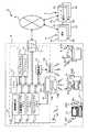
はじめに、本実施の形態の概念的な構成を説明する。図1は本実施の形態における接続制御装置の概念構成図である。この図において、接続制御装置100は、通信エリア200、二次元受光センサ300、パケットデータ送信部400、リソース割当テーブル500、パケットデータ受信部600、情報送信部700、テーブル変更制御部800、送信経路選択部900、及び、送信アンテナ901とで構成されている。通信エリア200は、詳述すると、光LANシステムで管理される例えば施設内(屋内)のオフィスを想定したものである。また、二次元受光センサ300はこのオフィス全体を見渡せる位置、例えば天井に敷設されるものであり、情報送信部700は、規則的に配列された複数個のLEDで構成されている。 First, the conceptual configuration of the present embodiment will be described. FIG. 1 is a conceptual configuration diagram of a connection control device according to the present embodiment. In this figure, the
二次元受光センサ300は通信エリア200内に存在する接続対象が輝度変調を伴って送信した情報(望ましくはLED等の発光デバイスが所定のパターンを伴って明滅発光することによる輝度変化パターン)201、202を受光する。二次元受光センサ300においてハッチングを付けた箇所301、302は各々情報201、202を受光した素子である。以下、二次元受光センサ300の受光面全面を基準にした受光素子301の位置を示す座標値を(X301,Y301)で表し、受光素子302の座標値を(X302,Y302)で表すことにする。 The two-dimensional
座標値(X301,Y301)で受光した情報201と、座標値(X302,Y302)で受光した情報202は、パケットデータ送信部400へ出力され、パケットデータ送信部400は図外のネットワークへ出力するためのパケットデータの生成が行なわれる。
一方、二次元受光センサ300が情報201、202を受光すると、リソース割当テーブル500で各々の情報201、202の物理位置情報の登録、および、この物理位置情報(上記座標値(X301,Y301)、(X302,Y302)で特定される情報)とネットワーク上に設定される論理位置情報との関連付けが行われる。また、受光した情報がその接続対象を特定するアドレス(論理位置情報)である場合は、物理位置情報に対応付けてそのアドレスも記憶する。The
On the other hand, when the two-dimensional
したがって、パケットデータ送信部400は接続対象から送信された情報からネットワークへ送信すべきパケットデータを生成する際、この情報を送信した接続対象の物理位置情報に対応する論理位置情報をリソース割当テーブル500から取得し、この情報から変換されたパケットデータに送信元アドレスとしてセットして、ネットワークへ送信することができる。 Therefore, when the packet
一方、パケットデータ受信部600は、ネットワークから出力されるパケットデータを受信して送信すべき情報に変換する。また、パケットデータ受信部600は、上記パケットデータを受信すると、このパケットデータに付加された送信先アドレスを論理位置情報として、リソース割当テーブル500を参照して対応する物理位置情報を特定し、上記パケットデータから変換された送信すべき情報を輝度変化パターンに変調してこの物理位置情報に対応する位置にあるLEDを明滅制御する。例えば、座標値(X301,Y301)で特定される接続対象に対しては、LED701を明滅駆動させて輝度変化パターンに変調された情報を発光する。また、座標値(X302,Y302)で特定される接続対象に対しては、LED702を明滅駆動させて輝度変化パターンに変調された情報を発光する。 On the other hand, the packet
テーブル変更制御部800は、一定時間間隔で二次元受光センサ300の受光状態を取得し、この各受光素子の受光状態とリソース割当テーブル500の登録内容とを照合し、登録済みの受光素子に変化があったか否か、新たに情報を受光した受光素子を検出したか否かを判断する。また、変化があった場合、リソース割当テーブル500を更新する処理を行う。 The table
送信経路選択部900は、リソース割当テーブル500の更新状況に基づいて、送信すべき情報をLEDの明滅制御により送信するか、アンテナ901を介して無線で送信するかを選択する。すなわち、一定時間内にリソース割当テーブル500の登録内容が変更されていなければ、接続対象は移動していないと判断し、この接続対象に最も近いLEDを明滅させるが、リソース割当テーブル500の登録内容が変更されていれば、接続対象は移動していると判断し、IEEE802シリーズに代表される無線通信方式で情報を送信する。 Based on the update status of the resource allocation table 500, the transmission
これにより、通信エリア内において接続対象が任意にその位置を変更しても、ネットワークより受信したパケットデータに基づく情報を確実に送信先の接続対象に送信することができる。以上説明した本発明の技術思想に係る接続制御装置100の各構成要素、すなわち、通信エリア200、二次元受光センサ300、パケットデータ送信部400、リソース割当テーブル500、パケットデータ受信部600、情報送信部700、テーブル変更制御部800、及び、送信経路選択部900は、様々な実施の態様をとることができ、以下にその態様の一例を説明する。 As a result, even if the connection target arbitrarily changes its position in the communication area, information based on the packet data received from the network can be reliably transmitted to the transmission destination connection target. Each component of the
図2(a)は本実施の形態におけるネットワークシステムの全体構成図である。ネットワークシステム1は、ネットワーク2、通信エリア3、通信エリア外の端末群4およびサーバ群5などで構成されている。なお、“通信エリア外”とは通信エリア3の外部に位置していることを意味する。 FIG. 2A is an overall configuration diagram of the network system in the present embodiment. The
ネットワーク2は、イーサネット(登録商標)、ECHONET、IEEE1394、HomePNAなどの有線系またはBluetoothなどの無線系の通信媒体であり、汎用の通信プロトコル(例えばTCP/IP)を用いて通信エリア3、端末群4およびサーバ群5の間の情報伝達を媒介するものである。端末群4は、例えば、複数の端末4a〜4dで構成されており、各端末4a〜4dは、少なくとも当該ネットワークシステム1の中でユニークな固有の識別情報(アドレス)を有するとともに、サーバ群5によって提供される各種サービスまたは通信エリア3の内部に存在する各種リソースを利用可能な所要のアプリケーションプログラムおよび上記プロトコルをサポートするネットワークOSを搭載している。 The
サーバ群5は、リソース割り付けサーバ5aやその他のサーバ(例えば、メールサーバやファイルサーバ等)5b〜5dで構成されており、各サーバ5a〜5dは、端末群4と同様に少なくとも当該ネットワークシステム1の中でユニークな固有の識別情報(アドレス)を有するとともに、各サーバサービスを提供するためのアプリケーションプログラムおよび上記プロトコルをサポートするネットワークOSを搭載している。 The
次に、通信エリア3について説明する。この通信エリア3は、前述の通信エリア200に相当し、オフィス全体を見渡せる位置、例えば天井に敷設されたブリッジコントローラ6(前述の接続制御装置100に相当)と端末71〜73を含む。ブリッジコントローラ6から下向きに発光するダウンリンク光DLは端末71〜73の受光部211〜213で受光される一方、端末71〜73の発光部201〜203が発光することにより出力されるアップリンク光ULはブリッジコントローラ6の撮像部16で受光される。またこのアップリンク光ULは、端末71〜73またはネットワーク2上の他の端末4a〜4dもしくはサーバ5a〜5dなどに伝達する情報を含んでいる。 Next, the
ブリッジコントローラ6は、所定の制御プログラムに従って全体を制御するCPU10、その制御プログラムなどを格納するプログラムメモリ11、CPU10の主記憶として機能するワークメモリ12、前述の汎用プロトコル(以下便宜的に「TCP/IP」とする)に従ってブリッジコートローラ6とネットワーク2との間のデータ転送を実行するネットワークインターフェース(I/F)13、CPU10からの送信情報に応じた駆動信号を生成する駆動部14、その駆動信号に従ってダウンリンク光DLを発生する複数のLEDからなる発光部15、通信エリア3の二次元画像を撮影してその画像信号を出力する撮像部16、撮像部16から出力された画像信号を保持するフレームバッファメモリ17、撮像部16から出力された画像信号に含まれる端末71〜73の発光部201〜203が発光したアップリンク光ULを変換した情報を保持するデータバッファメモリ18、端末71〜73の位置情報を保持する位置情報テーブルメモリ19(リソース割当テーブル500に相当)、無線通信部20、および、アンテナ21を備える。 The
ブリッジコントローラ6の撮像部16は、発光部201〜203で発光したアップリンク光ULを空間的に分離するレンズ16aと、アップリンク光ULの波長域の通過特性を有する光学フィルター16bと、これらの光学素子(レンズ16aおよび光学フィルター16b)を通過した通信エリア3内の画像を画像信号に変換して所定周期ごとに出力する二次元画像センサ16cを含み、二次元画像センサ16cには、例えば、N×M画素(以下便宜的に「N=16、M=16」とする)構成のインターライン転送型CCDが用いられている。 The
無線通信部20は、CPU10の制御により動作し、位置情報テーブルメモリ19の登録内容が変更されることにより、ネットワーク2より受信したパケットデータの送信先に対応する物理位置が特定できないときに、パケットデータを変換して生成した送信すべき情報を受け取り、無線信号で送信すべき情報に変換する機能を備える。また、アンテナ21は無線通信部20にて変換された情報を電波として放射する機能を備える。 The
通信エリア3内には可搬性を有する端末71、デスクトップコンピュータ等、据置型の端末72、及び、プリンタや、投影機等、ネットワーク2を介して出力依頼された情報を印刷、投影、表示等を行って出力する端末73が存在している。これらの端末71〜73は送信すべき情報を輝度変化パターンに変調させてアップリンク光ULとして発光する発光部201〜203、ブリッジコントローラ6の発光部15にて発光したダウンリンク光DLを受光し、そのダウンリンク光DLに含まれる情報を変換して再生する受光部211〜213、および、本来、ダウンリンク光DLとして生成すべき情報を無線信号で受信するためのアンテナ221〜223を備える。端末71〜73は、受信した情報が自端末宛てである場合にその受信情報を予め具備する所定のアプリケーションプログラムに渡す一方、必要に応じて所定のアプリケーションで送信すべき情報を生成する。 In the
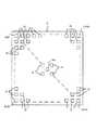
図2(b)は、本実施の形態における屋内、施設内のフロアの天井の態様を示すものである。同図において、天井Cの中心位置には、撮像部16のレンズ16aが配置されており、その周辺には複数の発光部15が規則的に配置されている。そして、複数の発光部15は二次元画像センサ16cの画素の配列に対応して個別に発光するようになっており、これにより、このフロアに設置された端末71〜73は、自己宛に送信されたパケットデータをこのパケットデータに対応して輝度変調する直上の発光部15により受信(受光)することができる。したがって端末71〜73は自己宛のパケットデータを受信(受光)するために広角の撮像素子を用意する必要は無くなる。 FIG. 2B shows an aspect of the ceiling of the floor in the facility and facility in the present embodiment. In the figure, the
尚、図2(b)において、発光部16はそれ自体が1つの発光素子(LED)として発光しても良いし、発光部15自体を個々の照明施設としてその一部が輝度変化するようにしても良い。次に、ブリッジコントローラ6を中心とした動作の概要について説明する。ブリッジコントローラ6は、大きく分けて、「位置情報管理処理機能」、「情報伝達処理機能」を有する。 In FIG. 2B, the
(1)位置情報管理機能
位置情報管理機能は、端末71〜73の物理位置と論理位置の対応関係を管理する機能である。物理位置とは端末71〜73の通信エリア3内に存在する位置であり、論理位置とはネットワーク上に展開されるアドレスのことである。端末71〜73の物理位置と論理位置の対応関係情報は位置情報テーブルメモリ19に登録されており、この登録情報は受光部16から取り出される画像信号に基づいて逐次更新されるようになっている。(1) Location Information Management Function The location information management function is a function that manages the correspondence between the physical positions and logical positions of the
(2)情報伝達処理機能
通信エリア3内外の端末同士で行われる情報伝達を中継する機能であり、その機能については図3(a)の機能概念図を用いて図示する。ブリッジコントローラ6は、発光部15、受光部16、イーサネット(登録商標)I/F13が備えるイーサネット(登録商標)入力部131、および、イーサネット(登録商標)出力部132との間に複数の経路a〜cを形成する。そして、これらの経路を使い分けながら、通信エリア内情報伝達機能および通信エリア内外情報伝達機能を実現する。(2) Information transmission processing function This is a function for relaying information transmission performed between terminals inside and outside the
例えば、通信エリア3内の端末71〜73間の情報の伝達の場合は経路aを用い、通信エリア3内の端末71〜73からネットワーク2を介して端末群4やサーバ群5へ情報を伝達する場合は経路b、逆にネットワーク2を介して端末群4やサーバ群5から通信エリア3内の端末71〜73へ情報を伝達する場合は経路cを用いる。 For example, in the case of transmitting information between the
図3(b)はアップリンク光ULやダウンリンク光DLとして通信されるネットワークパケットデータ140の構造図であり、OSI(Open System Interconnection)参照モデルのデータリンク層のパケット構造に対応するものである。パケットデータ140は、宛先アドレスのフレーム141、送り元アドレスのフレーム142および情報フレーム143で構成されており、フレーム141に設定される宛先アドレスとフレーム142に設定される送り元アドレスは、例えば、MAC(Media Access Control)アドレスである。
図4(a)〜(c)は、端末71、ブリッジコントローラ6、リソース割付サーバ5aのイーサネット(登録商標)プロトコルを示すものである。FIG. 3B is a structural diagram of
4A to 4C show the Ethernet (registered trademark) protocol of the terminal 71, the
同図において端末71には、ネットワークインターフェース層(OSI参照モデルの第1層と第2層に相当)に光通信処理710と無線通信処理715、インターネットワーク層(OSI参照モデルの第3層に相当)にIP(ICMP、APP)711、トランスポート層(OSI参照モデルの第4層に相当)にTCP(UDP)712、及び、アプリケーション層(OSI参照モデルの第5〜7層に相当)にネットワークアプリケーション713とワークグループ等の自動設定アプリケーション714が設定される。 In the figure, the terminal 71 has an
また、ブリッジコントローラ6には、ネットワークインターフェース層に光通信処理601とイーサネット(登録商標)通信処理605と無線通信処理606、インターネットワーク層にIP(ICMP、APP)602、トランスポート層にTCP(UDP)603、及び、アプリケーション層に端末位置応答アプリケーション604が設定される。また、リソース割付サーバ5aには、ネットワークインターフェース層にイーサネット(登録商標)通信処理501、インターネットワーク層にIP(ICMP、APP)502、トランスポート層にTCP(UDP)503、及び、アプリケーション層にリソース割付サービスアプリケーション504が設定される。 The
次に、ブリッジコントローラ6における位置情報管理の仕組みについて説明する。 Next, the position information management mechanism in the
図5(a)はブリッジコントローラ6の受光部16から出力される画像信号160の概念図である。図において画像信号160は、(0,0)から(15,15)までの256個の画素を有している。ここで、画像信号160の領域A、Bは、所定値以上の輝度で露光された領域であり、通信エリア内の任意の端末71〜73の発光部201〜221からのアップリンク光ULで露光された領域を表している。ブリッジコントローラ6は、この領域A、Bの代表画素の座標値を取り出して位置情報テーブルメモリ19に登録する。図5(b)は領域A、Bの位置情報を登録した位置情報テーブルメモリ19の概念図であり、現在(3,12)と(2,2)の二つの代表画素座標値が登録されている。このように位置情報テーブルメモリ19には、所定値以上の輝度値で露光された領域(図5では領域A、B)の物理位置情報(代表画素座標値)が登録される。さらに、位置情報テーブルメモリ19には、アップリンク光ULを二次元画像センサ16cが時系列的に連続して撮像することにより、その輝度変調を復号して得られた端末71〜73に設定された固有の情報(例えば、MACアドレス)も登録される。 FIG. 5A is a conceptual diagram of the
次に、ブリッジコントローラ6のCPU10で実行される制御プログラムの動作について説明する。 Next, the operation of the control program executed by the
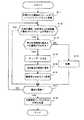
図6はブリッジコントローラ6のCPU10が処理する位置情報テーブルメモリ登録/更新処理のフローチャートであり、当該処理は、所定時間間隔(例えば30分間隔)で行われる。まず、ステップS11で二次元画像センサ16cからの画像信号160を一定時間複数フレームに渡って取得し、取得された複数のフレームをフレームバッファメモリ17に蓄積する。そして、ステップS12で取得されたフレームの数分、画像信号160の座標値(0,0)の画素から所定値以上の輝度値で露光されたフレームが存在するか否か判断し、更に、ステップS12でその座標値の画素が所定値以上の輝度値で露光されているフレームが存在すると判断された場合には、ステップS13でその露光された画素を持つフレームが所定時間間隔で存在するか否かを判断する。 FIG. 6 is a flowchart of the position information table memory registration / update process processed by the
所定値以上の輝度値で露光されたフレームが存在すると判断し(ステップS12でYes)、更にその露光された画素を持つフレームが所定時間間隔で存在する(ステップS13でYes)と判断すると、当該画素が輝度変調された情報を取得したものと判断して、ステップS14で複数のフレームに渡って存在する“所定値以上の輝度で露光した状態”を“1”ビット、“露光していない状態”を“0”ビットとして取得したフレーム順に並べてビットデータを生成する。そして、続くステップS15でこのビットデータを復号して端末固有の情報に復号し、ステップS16でデータバッファメモリ18に座標値と対応付けて端末固有の情報を記憶し、ステップS17で今回判断した画素の座標値が、(15,15)、すなわち最後の画素か否か判断し、最後の画素であれば、ステップS18の位置情報テーブルメモリ19との照合処理に進む。 If it is determined that there is a frame exposed with a luminance value greater than or equal to a predetermined value (Yes in step S12), and if it is determined that frames with the exposed pixels exist at predetermined time intervals (Yes in step S13), It is determined that the information obtained by modulating the luminance of the pixel is obtained, and in step S14, the “exposed state with a luminance higher than a predetermined value” existing over a plurality of frames is “1” bit, and “not exposed” Bit data is generated by arranging "" as "0" bits in the order of acquired frames. In step S15, the bit data is decoded and decoded into terminal-specific information. In step S16, terminal-specific information is stored in the data buffer memory 18 in association with the coordinate value. Is determined to be (15, 15), that is, the last pixel, and if it is the last pixel, the process proceeds to the collation process with the position
一方、所定値以上の輝度値で露光されたフレームが存在すると判断し(ステップS12でYes)、その露光された画素を持つフレームが所定時間間隔で存在しない(ステップS13でNo)と判断すると、当該画素は外乱光を取得したものと判断して、ステップS19でその座標値については情報を取得しなかったものと判断して破棄する。そして、ステップS17で今回判断した画素の座標値が、(15,15)、すなわち最後の画素か否か判断し、最後の画素であれば、ステップS18の位置情報テーブルメモリ19との照合処理に進む。 On the other hand, if it is determined that there is a frame exposed with a luminance value greater than or equal to a predetermined value (Yes in step S12), and it is determined that there is no frame having the exposed pixel at a predetermined time interval (No in step S13), The pixel is determined to have acquired disturbance light, and in step S19, it is determined that information has not been acquired for the coordinate value and is discarded. Then, it is determined whether or not the coordinate value of the pixel determined this time in step S17 is (15, 15), that is, whether it is the last pixel. If it is the last pixel, the collation process with the position
また、一方、所定値以上の輝度値で露光されたフレームが存在しないと判断し(ステップS12でNo)と判断すると、ステップS19でその座標値については情報を取得しなかったものと判断して破棄する。そして、ステップS17で今回判断した画素の座標値が、(15,15)、すなわち最後の画素か否か判断し、最後の画素であれば、ステップS18の位置情報テーブルメモリ19との照合処理に進む。尚、ステップS12〜S17の処理の詳細な態様については、その概要は特願2001−286891号にて開示された技術にほぼ同じであるので、省略する。 On the other hand, if it is determined that there is no frame exposed with a luminance value greater than or equal to the predetermined value (No in step S12), it is determined in step S19 that no information has been acquired for the coordinate value. Discard. Then, it is determined whether or not the coordinate value of the pixel determined this time in step S17 is (15, 15), that is, whether it is the last pixel. If it is the last pixel, the collation process with the position
ステップS18では、上記ステップS12〜17における処理の結果、データバッファメモリ18に記憶された座標値及び端末固有の情報と、位置情報テーブルメモリ19に格納されている座標値及び端末固有の情報との照合を行い、一括して更新する処理である。
具体的には、データバッファメモリ18に記憶された座標値と位置情報テーブルメモリ19に格納されている座標値とを照合し、双方に同じ固有の情報が記憶されていれば、通信エリア3内に存在する端末71〜73の移動等による位置の変化が無いものと判断してその座標については更新せず、一方、データバッファメモリ18に記憶された座標値と位置情報テーブルメモリ19に格納されている座標値とを照合した結果、固有の情報が異なる、または、消滅、若しくは、新しく出現していると、更新前には通信エリア3内に存在していた端末71〜73が通信エリア3から移動した(移動して通信エリア3に存在しなくなった)、若しくは、新たに通信エリア3の通信圏内に入ったものと判断し、その座標値についてデータバッファメモリ18に記憶された固有の情報を位置情報テーブルメモリ19の座標値に対応する固有の情報として書き換え、更新する。このようにして、位置情報テーブルメモリ登録/更新処理を終了する。In step S18, as a result of the processing in steps S12 to S17, the coordinate values and terminal-specific information stored in the data buffer memory 18, and the coordinate values and terminal-specific information stored in the position
Specifically, the coordinate value stored in the data buffer memory 18 is compared with the coordinate value stored in the position
次に、通信エリア外から送信されたネットワークパケットデータを通信エリア3に出力する場合について詳述する。 Next, the case where network packet data transmitted from outside the communication area is output to the
図7はCPU10が処理するイーサネット(登録商標)ポート入力処理を説明するフローチャートである。このフローチャートを実行すると、まず、ステップS21でネットワークパケットデータを宛先アドレスのフレーム141、送り元アドレスのフレーム142および情報フレーム143に分解する。 FIG. 7 is a flowchart for explaining an Ethernet (registered trademark) port input process processed by the
次に、ステップS22で、宛先アドレスのフレーム141に設定される宛先アドレスを固有の情報とし、位置情報テーブルメモリ19に同じ固有の情報が格納されているか否かを判断する。そして固有の情報が格納されている場合、ステップS23でフレーム142に格納される送り元アドレス、及び、情報フレーム143に格納される情報を輝度変調情報に変換し、上記の固有の情報と対応付けられた座標値を読み出し、ネットワークインターフェース層にある光通信処理601を経由して、この読み出された座標値に対応する発光部15に対し、この輝度変調情報に基づいて発光するよう制御する。 Next, in
次にステップS24において今回の送信に対し、確認応答(ACK)を受け取ったか否かを判断する。この判断は、宛て先アドレスに対応する座標値の画素で、確認応答情報を輝度変調情報として受光したか否かの判断であり、確認応答(ACK)を受信した場合は、ステップS25でこの確認応答をネットワークI/F13に出力して本処理を終了する。尚、上記のステップS24では、宛て先アドレスに対応する座標値の画素で確認応答情報を輝度変調情報として受光したか否かを判断するようにしたが、座標値を特定せず、二次元画像センサ16c全領域で検出できたか否か判断するようにしてもよく、二次元画像センサ16c全領域で検出する場合については、確認応答を受光した画素の座標値を位置情報テーブルメモリ19に格納される固有の情報と対応付けて記憶・更新するようにしても良い。このようにすることで、最新の端末の位置を位置情報テーブルメモリ19に記憶させることができる。 In step S24, it is determined whether an acknowledgment (ACK) has been received for the current transmission. This determination is a determination as to whether or not the confirmation response information is received as luminance modulation information at the pixel of the coordinate value corresponding to the destination address. When the confirmation response (ACK) is received, this confirmation is performed in step S25. The response is output to the network I /
一方、ステップS24で確認応答(ACK)の受信を確認できなかった場合、または、ステップS22で、位置情報テーブルメモリ19に同じ固有の情報が格納されていないと判断した場合、ステップS26でデータバッファメモリ18に同じ固有の情報が格納されているか否かを判断する。これは、今回のイーサネット(登録商標)ポート入力処理タイミングと位置情報テーブルメモリ登録/更新処理タイミングがほぼ同時である場合に、データバッファメモリ18に格納される最新の通信エリアの状況に基づいて、宛て先アドレスに対応する端末を特定するためである。 On the other hand, if reception of the confirmation response (ACK) cannot be confirmed in step S24, or if it is determined in step S22 that the same unique information is not stored in the position
上記ステップS26において、固有の情報が格納されていると判断した場合、ステップS27でフレーム142に格納される送り元アドレス、及び、情報フレーム143に格納される情報を輝度変調情報に変換し、データバッファメモリ18に格納される上記の固有の情報と対応付けられた座標値を読み出し、ネットワークインターフェース層にある光通信処理601を経由して、この読み出された座標値に対応する発光部15に対し、この輝度変調情報に基づいて発光するよう制御する。したがって、通信エリア3内で端末71〜73が移動した場合であっても、この移動先に対応して発光部15を発光させることができる。 If it is determined in step S26 that the unique information is stored, the source address stored in the
また、ステップS26において、固有の情報が格納されていないと判断した場合、通信エリア3内にこの宛て先アドレスに相当する端末は存在しないものと判断し、ステップS27で送信元アドレスを宛て先アドレスに設定し、エラーを送信する。ステップS29では今回の送信に対し、確認応答(ACK)を受け取ったか否かを判断する。確認応答(ACK)を受信した場合は、ステップS25でこの確認応答をネットワークI/F13に出力して本処理を終了する。 If it is determined in step S26 that the unique information is not stored, it is determined that there is no terminal corresponding to the destination address in the
一方、ステップS29で確認応答(ACK)の受信を確認できなかった場合、ステップS30でフレーム142に格納される送り元アドレス、及び、情報フレーム143に格納される情報を無線信号に変調し、ネットワークインターフェース層にある無線通信処理605を経由して、無線処理部20、アンテナ21を経由して送信する。これは、例えば端末71〜73が通信エリア3に存在するのにも関わらず、発光部15と受光部211〜213の受光面との間に遮蔽物が存在する場合や、端末71〜73において受光部211〜213を動作させないように設定した場合による光による通信が不可能な場合の措置である。このようにすることで、通信エリア内に存在する端末71〜73に対し、確実に情報を送信することができる。 On the other hand, if reception of the acknowledgment (ACK) cannot be confirmed in step S29, the source address stored in the
次にステップS31において今回の送信に対し、確認応答(ACK)を無線、或いは、受光により受け取ったか否かを判断する。確認応答(ACK)を受信した場合は、ステップS25でこの確認応答をネットワークI/F13に出力して本処理を終了する。一方、ステップS31において今回の送信に対し、確認応答(ACK)の受信を確認できなかった場合は、ステップS27で送信元アドレスを宛て先アドレスに設定し、エラーを送信する。 Next, in step S31, it is determined whether or not an acknowledgment (ACK) is received by radio or light reception for the current transmission. If the confirmation response (ACK) is received, this confirmation response is output to the network I /
このように本実施の形態のブリッジコントローラ6によれば、定期的に自己が管轄する通信エリア内の端末の位置を更新するので、端末が移動しても、その移動に対応して発光制御する発光部を選択することができる他、光による通信が不可能な場合であっても、管轄する通信エリア内に存在することが分かっていれば、他の通信インフラ設備で通信を行うことができる。したがって、端末位置が変更されても、確実に通信処理を行うことができる。 As described above, according to the
尚、本実施の形態では、屋内に設置されたブリッジコントローラを例示して詳述したが、これに限定されること無く、光を通信媒体として通信を処理を行う環境と、この環境の外部に存在するネットワークとの中継を行う技術であれば、本実施の形態に限定されることなく適用可能である。 In the present embodiment, the bridge controller installed indoors has been exemplified and described in detail. However, the present invention is not limited to this, and an environment in which communication is processed using light as a communication medium and an environment outside this environment are not limited thereto. Any technology that relays to an existing network can be applied without being limited to the present embodiment.
UL アップリンク光
DL ダウンリンク光
1 ネットワークシステム
2 ネットワーク
3 通信エリア
6 ブリッジコントローラ
13 ネットワークI/F
15 発光部
16 撮像部
16a レンズ
16c 二次元画像センサ
18 データバッファメモリ
19 位置情報テーブルメモリ
20 無線通信部
21 アンテナ
71 端末
140 パケットデータ
201 発光部
211 受光部UL Uplink Optical
DESCRIPTION OF
Claims (4)
Translated fromJapanese規則的に二次元配置された複数の受光素子を有する光検知手段と、
この光検知手段における前記発光装置が発光する輝度を感知した受光素子の座標位置を取得する座標位置取得手段と、
この座標位置取得手段によって取得された座標位置と前記ネットワーク上の論理位置とを関連付けて記憶する記憶手段と、
前記記憶手段によって記憶された座標位置と新たに前記座標位置取得手段によって取得された座標位置とに変化があったか否かを判断する判断手段と、
この判断手段により双方の座標位置に変化があったと判断すると、前記記憶されている座標位置に関連付けられた論理位置を変更して記憶するよう制御する記憶制御手段と
を備えたことを特徴とする接続制御装置。In a connection control device for controlling connection between a connection target specified by a light emitting device and a logical position on a network assigned to the connection target,
Photodetecting means having a plurality of light receiving elements regularly arranged two-dimensionally;
Coordinate position acquisition means for acquiring the coordinate position of the light receiving element that senses the luminance emitted by the light emitting device in the light detection means;
Storage means for storing the coordinate position acquired by the coordinate position acquisition means and the logical position on the network in association with each other;
Determination means for determining whether or not there is a change between the coordinate position stored by the storage means and the coordinate position newly acquired by the coordinate position acquisition means;
Storage means for controlling to change and store the logical position associated with the stored coordinate position when the determination means determines that both coordinate positions have changed. Connection control device.
前記記憶手段は、更にこの情報生成手段によって生成された情報を前記ネットワーク上の論理位置と関連付けて記憶することを特徴とする
請求項1に記載の接続制御装置。When the light emission luminance of the light emitting device emits light with a temporal change, further comprising information generating means for generating information specific to the light emitting device from the temporal change,
The connection control apparatus according to claim 1, wherein the storage unit further stores the information generated by the information generation unit in association with the logical position on the network.
この第2の受信手段によって受信されたデータから当該データの送信先の論理位置を検出する論理位置検出手段と、
この論理位置情報手段により論理位置が検出されると、前記記憶制御手段によりこの論理位置に関連付けられた座標位置について変更があったか否かを判断する判断手段と、
前記判断手段により変更があったと判断されると、前記情報生成手段によって生成された情報を送信先として前記データを送信し、変更が無かったと判断されると前記座標位置を送信先として前記データを送信することを特徴とする請求項2に記載の接続制御装置。Second receiving means for receiving data from the network;
Logical position detecting means for detecting the logical position of the transmission destination of the data from the data received by the second receiving means;
When the logical position is detected by the logical position information means, the storage control means determines whether the coordinate position associated with the logical position has changed,
When it is determined that there is a change by the determination unit, the data is transmitted using the information generated by the information generation unit as a transmission destination, and when it is determined that there is no change, the data is transmitted using the coordinate position as a transmission destination. The connection control device according to claim 2, wherein the connection control device transmits.
規則的に二次元配置された複数の受光素子を有する輝度検知部から、外部の発光装置が発光する輝度を検知した受光素子の座標位置を取得する座標位置取得手段、
この座標位置取得手段によって取得された座標位置と前記ネットワーク上の論理位置とを関連付けて記憶部に記憶させる記憶手段、
前記記憶手段によって記憶された座標位置と新たに前記座標位置取得手段によって取得された座標位置とに変化があったか否かを判断する判断手段、
この判断手段により双方の座標位置に変化があったと判断すると、前記記憶されている座標位置に関連付けられた論理位置を変更して記憶するよう制御する記憶制御手段
として機能させることを特徴とするネットワーク接続制御プログラム。Computer
Coordinate position acquisition means for acquiring the coordinate position of the light receiving element that has detected the luminance emitted by the external light emitting device from the luminance detection unit having a plurality of light receiving elements regularly arranged in two dimensions,
Storage means for associating and storing the coordinate position acquired by the coordinate position acquisition means and the logical position on the network in the storage unit;
Determination means for determining whether or not there is a change between the coordinate position stored by the storage means and the coordinate position newly acquired by the coordinate position acquisition means;
A network that functions as a storage control unit that controls to change and store a logical position associated with the stored coordinate position when the determination unit determines that there is a change in both coordinate positions. Connection control program.
Priority Applications (2)
| Application Number | Priority Date | Filing Date | Title |
|---|---|---|---|
| JP2007146943AJP4487211B2 (en) | 2007-06-01 | 2007-06-01 | Connection control apparatus and network connection control program |
| US12/130,019US7970282B2 (en) | 2007-06-01 | 2008-05-30 | Network repeater, repeater controlling method and program product |
Applications Claiming Priority (1)
| Application Number | Priority Date | Filing Date | Title |
|---|---|---|---|
| JP2007146943AJP4487211B2 (en) | 2007-06-01 | 2007-06-01 | Connection control apparatus and network connection control program |
Publications (2)
| Publication Number | Publication Date |
|---|---|
| JP2008301345Atrue JP2008301345A (en) | 2008-12-11 |
| JP4487211B2 JP4487211B2 (en) | 2010-06-23 |
Family
ID=40088345
Family Applications (1)
| Application Number | Title | Priority Date | Filing Date |
|---|---|---|---|
| JP2007146943AExpired - Fee RelatedJP4487211B2 (en) | 2007-06-01 | 2007-06-01 | Connection control apparatus and network connection control program |
Country Status (2)
| Country | Link |
|---|---|
| US (1) | US7970282B2 (en) |
| JP (1) | JP4487211B2 (en) |
Cited By (2)
| Publication number | Priority date | Publication date | Assignee | Title |
|---|---|---|---|---|
| JP2016178528A (en)* | 2015-03-20 | 2016-10-06 | カシオ計算機株式会社 | Decoder, decoding method, and program |
| JPWO2024062617A1 (en)* | 2022-09-22 | 2024-03-28 |
Families Citing this family (6)
| Publication number | Priority date | Publication date | Assignee | Title |
|---|---|---|---|---|
| US7263290B2 (en)* | 2002-06-06 | 2007-08-28 | Lucent Technologies Inc. | Network operating system with distributed data architecture |
| JP4552074B2 (en)* | 2008-05-29 | 2010-09-29 | カシオ計算機株式会社 | Information transmission system, information decoding apparatus, notification method, and program |
| US9450671B2 (en)* | 2012-03-20 | 2016-09-20 | Industrial Technology Research Institute | Transmitting and receiving apparatus and method for light communication, and the light communication system thereof |
| US9692508B2 (en)* | 2013-07-01 | 2017-06-27 | Nokia Technologies Oy | Directional optical communications |
| JP6168108B2 (en)* | 2015-06-29 | 2017-07-26 | カシオ計算機株式会社 | COMMUNICATION DEVICE, SERVER DEVICE, COMMUNICATION DEVICE CONTROL METHOD, AND PROGRAM |
| JP7136141B2 (en)* | 2020-02-07 | 2022-09-13 | カシオ計算機株式会社 | Information management device, information management method and program |
Family Cites Families (24)
| Publication number | Priority date | Publication date | Assignee | Title |
|---|---|---|---|---|
| US5099346A (en)* | 1988-01-27 | 1992-03-24 | Spectrix Corporation | Infrared communications network |
| WO1991015907A2 (en) | 1990-04-09 | 1991-10-17 | Ascom Tech Ag | Bit and frame synchronizing unit for an access node in an optical transmission device |
| US5812865A (en)* | 1993-12-03 | 1998-09-22 | Xerox Corporation | Specifying and establishing communication data paths between particular media devices in multiple media device computing systems based on context of a user or users |
| US5555376A (en)* | 1993-12-03 | 1996-09-10 | Xerox Corporation | Method for granting a user request having locational and contextual attributes consistent with user policies for devices having locational attributes consistent with the user request |
| US5493692A (en)* | 1993-12-03 | 1996-02-20 | Xerox Corporation | Selective delivery of electronic messages in a multiple computer system based on context and environment of a user |
| WO1996011539A2 (en)* | 1994-10-04 | 1996-04-18 | Sdl, Inc. | Infrared laser diode wireless local area network |
| US5982520A (en)* | 1996-03-28 | 1999-11-09 | Xerox Corporation | Personal storage device for application and data transfer |
| US6348986B1 (en)* | 1996-03-29 | 2002-02-19 | Dominion Lasercom. Inc. | Wireless fiber-coupled telecommunication systems based on atmospheric transmission of laser signals |
| JPH11274990A (en) | 1998-03-25 | 1999-10-08 | Taisei Corp | Wiring system |
| US6307487B1 (en)* | 1998-09-23 | 2001-10-23 | Digital Fountain, Inc. | Information additive code generator and decoder for communication systems |
| CA2266998C (en)* | 1999-03-25 | 2008-01-15 | Canac Inc. | Method and apparatus for assigning addresses to components in a control system |
| US6654779B1 (en)* | 1999-04-14 | 2003-11-25 | First Data Resources | System and method for electronic mail (e-mail) address management |
| JP3799593B2 (en) | 2000-03-01 | 2006-07-19 | カシオ計算機株式会社 | Optical communication repeater |
| US6795655B1 (en)* | 2000-10-09 | 2004-09-21 | Meklyn Enterprises Limited | Free-space optical communication system with spatial multiplexing |
| JP4131097B2 (en) | 2000-12-27 | 2008-08-13 | カシオ計算機株式会社 | Image processing method, image processing apparatus, and image processing program |
| US7171124B2 (en)* | 2001-07-19 | 2007-01-30 | Lucent Technologies Inc. | Wavelength routing and switching mechanism for a photonic transport network |
| EP1345358B1 (en)* | 2002-03-11 | 2005-12-21 | Honda Giken Kogyo Kabushiki Kaisha | Optical wireless communication system |
| US6816728B2 (en)* | 2002-04-24 | 2004-11-09 | Teledyne Technologies Incorporated | Aircraft data communication system and method |
| GB2395856A (en)* | 2002-11-26 | 2004-06-02 | King S College London | Method for reducing packet congestion at a network node |
| US20040258415A1 (en)* | 2003-06-18 | 2004-12-23 | Boone Bradley G. | Techniques for secure free space laser communications |
| JP4351517B2 (en) | 2003-11-14 | 2009-10-28 | 株式会社日立製作所 | Data center device management method, device management server, data center device management system and program |
| JP2006086868A (en) | 2004-09-16 | 2006-03-30 | Seiko Precision Inc | Network control system and movement detecting method |
| US7466917B2 (en) | 2005-03-15 | 2008-12-16 | Fujitsu Limited | Method and system for establishing transmission priority for optical light-trails |
| US20080024489A1 (en)* | 2006-07-28 | 2008-01-31 | Robert Allen Shearer | Cache Utilization Optimized Ray Traversal Algorithm with Minimized Memory Bandwidth Requirements |
- 2007
- 2007-06-01JPJP2007146943Apatent/JP4487211B2/ennot_activeExpired - Fee Related
- 2008
- 2008-05-30USUS12/130,019patent/US7970282B2/enactiveActive
Cited By (3)
| Publication number | Priority date | Publication date | Assignee | Title |
|---|---|---|---|---|
| JP2016178528A (en)* | 2015-03-20 | 2016-10-06 | カシオ計算機株式会社 | Decoder, decoding method, and program |
| JPWO2024062617A1 (en)* | 2022-09-22 | 2024-03-28 | ||
| WO2024062617A1 (en)* | 2022-09-22 | 2024-03-28 | 株式会社センチュリーアークス | Optical communication system |
Also Published As
| Publication number | Publication date |
|---|---|
| US7970282B2 (en) | 2011-06-28 |
| US20080298812A1 (en) | 2008-12-04 |
| JP4487211B2 (en) | 2010-06-23 |
Similar Documents
| Publication | Publication Date | Title |
|---|---|---|
| JP4487211B2 (en) | Connection control apparatus and network connection control program | |
| CN111886845B (en) | Method and apparatus for performing over-the-air (OTA) upgrades in a network of communication interconnect devices | |
| US8861976B2 (en) | Transmit and receive MIMO protocols for light array communications | |
| CN102685852B (en) | Wireless network system, wireless device, and network registration method of wireless device | |
| JP4052522B2 (en) | Network device and network device management method | |
| EP3048747B1 (en) | Positioning method based on visible light source, mobile terminal and controller | |
| JP6724318B2 (en) | Projector and projector control method | |
| CN106031055A (en) | Multifunctional intelligent LED system with visible light communication and IP-based radio frequency connection | |
| US11038715B2 (en) | System and method for identifying specific/best path in a mesh network | |
| JP5770199B2 (en) | Method for communicating in a network having a batteryless ZigBee device, network and apparatus therefor | |
| TWI499327B (en) | Method for communicating in a network including a batteryless bee device and network and device thereof | |
| CN110023779B (en) | Control device, wireless communication terminal and position estimation system | |
| US10841201B2 (en) | System and method for managing and controlling a dynamic tunneling protocol in a mesh network | |
| US9686516B2 (en) | Method and device for improving configuration of communication devices in a video projection system comprising multiple wireless video projectors | |
| CN115836496A (en) | Optical wireless communication receiving unit, system and method | |
| JP3799593B2 (en) | Optical communication repeater | |
| KR20180058518A (en) | Method and Apparatus for Visible Light Communication | |
| CN113647057A (en) | Network system operating with predicted events | |
| JP2017062124A (en) | Imaging device | |
| JP2017017577A (en) | Connection information collating device | |
| CN112205033A (en) | System and method for managing and controlling dynamic tunneling protocol in a mesh network | |
| US10411826B2 (en) | Dynamic light channel | |
| JP7210863B2 (en) | remote control system | |
| WO2019186508A1 (en) | System and method for managing and controlling a dynamic tunneling protocol in a mesh network | |
| EP3836425B1 (en) | System and method for managing interference in optical camera communication based network |
Legal Events
| Date | Code | Title | Description |
|---|---|---|---|
| A977 | Report on retrieval | Free format text:JAPANESE INTERMEDIATE CODE: A971007 Effective date:20090525 | |
| A131 | Notification of reasons for refusal | Free format text:JAPANESE INTERMEDIATE CODE: A131 Effective date:20090527 | |
| A521 | Request for written amendment filed | Free format text:JAPANESE INTERMEDIATE CODE: A523 Effective date:20090717 | |
| A131 | Notification of reasons for refusal | Free format text:JAPANESE INTERMEDIATE CODE: A131 Effective date:20091022 | |
| A521 | Request for written amendment filed | Free format text:JAPANESE INTERMEDIATE CODE: A523 Effective date:20091215 | |
| TRDD | Decision of grant or rejection written | ||
| A01 | Written decision to grant a patent or to grant a registration (utility model) | Free format text:JAPANESE INTERMEDIATE CODE: A01 Effective date:20100304 | |
| A01 | Written decision to grant a patent or to grant a registration (utility model) | Free format text:JAPANESE INTERMEDIATE CODE: A01 | |
| A61 | First payment of annual fees (during grant procedure) | Free format text:JAPANESE INTERMEDIATE CODE: A61 Effective date:20100317 | |
| FPAY | Renewal fee payment (event date is renewal date of database) | Free format text:PAYMENT UNTIL: 20130409 Year of fee payment:3 | |
| R150 | Certificate of patent or registration of utility model | Ref document number:4487211 Country of ref document:JP Free format text:JAPANESE INTERMEDIATE CODE: R150 Free format text:JAPANESE INTERMEDIATE CODE: R150 | |
| FPAY | Renewal fee payment (event date is renewal date of database) | Free format text:PAYMENT UNTIL: 20130409 Year of fee payment:3 | |
| FPAY | Renewal fee payment (event date is renewal date of database) | Free format text:PAYMENT UNTIL: 20140409 Year of fee payment:4 | |
| LAPS | Cancellation because of no payment of annual fees |