JP2008301232A - Television receiver and device control method - Google Patents
Television receiver and device control methodDownload PDFInfo
- Publication number
- JP2008301232A JP2008301232AJP2007145643AJP2007145643AJP2008301232AJP 2008301232 AJP2008301232 AJP 2008301232AJP 2007145643 AJP2007145643 AJP 2007145643AJP 2007145643 AJP2007145643 AJP 2007145643AJP 2008301232 AJP2008301232 AJP 2008301232A
- Authority
- JP
- Japan
- Prior art keywords
- devices
- video signal
- television receiver
- command
- state
- Prior art date
- Legal status (The legal status is an assumption and is not a legal conclusion. Google has not performed a legal analysis and makes no representation as to the accuracy of the status listed.)
- Withdrawn
Links
Images


Classifications
- H—ELECTRICITY
- H04—ELECTRIC COMMUNICATION TECHNIQUE
- H04N—PICTORIAL COMMUNICATION, e.g. TELEVISION
- H04N5/00—Details of television systems
- H04N5/44—Receiver circuitry for the reception of television signals according to analogue transmission standards
- H—ELECTRICITY
- H04—ELECTRIC COMMUNICATION TECHNIQUE
- H04N—PICTORIAL COMMUNICATION, e.g. TELEVISION
- H04N21/00—Selective content distribution, e.g. interactive television or video on demand [VOD]
- H04N21/40—Client devices specifically adapted for the reception of or interaction with content, e.g. set-top-box [STB]; Operations thereof
- H04N21/41—Structure of client; Structure of client peripherals
- H04N21/4104—Peripherals receiving signals from specially adapted client devices
- H04N21/4108—Peripherals receiving signals from specially adapted client devices characterised by an identification number or address, e.g. local network address
- H—ELECTRICITY
- H04—ELECTRIC COMMUNICATION TECHNIQUE
- H04N—PICTORIAL COMMUNICATION, e.g. TELEVISION
- H04N21/00—Selective content distribution, e.g. interactive television or video on demand [VOD]
- H04N21/40—Client devices specifically adapted for the reception of or interaction with content, e.g. set-top-box [STB]; Operations thereof
- H04N21/43—Processing of content or additional data, e.g. demultiplexing additional data from a digital video stream; Elementary client operations, e.g. monitoring of home network or synchronising decoder's clock; Client middleware
- H04N21/442—Monitoring of processes or resources, e.g. detecting the failure of a recording device, monitoring the downstream bandwidth, the number of times a movie has been viewed, the storage space available from the internal hard disk
- H04N21/44231—Monitoring of peripheral device or external card, e.g. to detect processing problems in a handheld device or the failure of an external recording device
- H—ELECTRICITY
- H04—ELECTRIC COMMUNICATION TECHNIQUE
- H04N—PICTORIAL COMMUNICATION, e.g. TELEVISION
- H04N21/00—Selective content distribution, e.g. interactive television or video on demand [VOD]
- H04N21/40—Client devices specifically adapted for the reception of or interaction with content, e.g. set-top-box [STB]; Operations thereof
- H04N21/43—Processing of content or additional data, e.g. demultiplexing additional data from a digital video stream; Elementary client operations, e.g. monitoring of home network or synchronising decoder's clock; Client middleware
- H04N21/443—OS processes, e.g. booting an STB, implementing a Java virtual machine in an STB or power management in an STB
- H04N21/4436—Power management, e.g. shutting down unused components of the receiver
- H—ELECTRICITY
- H04—ELECTRIC COMMUNICATION TECHNIQUE
- H04N—PICTORIAL COMMUNICATION, e.g. TELEVISION
- H04N5/00—Details of television systems
- H04N5/76—Television signal recording
- H04N5/765—Interface circuits between an apparatus for recording and another apparatus
- H—ELECTRICITY
- H04—ELECTRIC COMMUNICATION TECHNIQUE
- H04N—PICTORIAL COMMUNICATION, e.g. TELEVISION
- H04N5/00—Details of television systems
- H04N5/76—Television signal recording
- H04N5/765—Interface circuits between an apparatus for recording and another apparatus
- H04N5/775—Interface circuits between an apparatus for recording and another apparatus between a recording apparatus and a television receiver
- H—ELECTRICITY
- H04—ELECTRIC COMMUNICATION TECHNIQUE
- H04N—PICTORIAL COMMUNICATION, e.g. TELEVISION
- H04N21/00—Selective content distribution, e.g. interactive television or video on demand [VOD]
- H04N21/40—Client devices specifically adapted for the reception of or interaction with content, e.g. set-top-box [STB]; Operations thereof
- H04N21/43—Processing of content or additional data, e.g. demultiplexing additional data from a digital video stream; Elementary client operations, e.g. monitoring of home network or synchronising decoder's clock; Client middleware
- H04N21/436—Interfacing a local distribution network, e.g. communicating with another STB or one or more peripheral devices inside the home
- H04N21/4363—Adapting the video stream to a specific local network, e.g. a Bluetooth® network
- H04N21/43632—Adapting the video stream to a specific local network, e.g. a Bluetooth® network involving a wired protocol, e.g. IEEE 1394
- H04N21/43635—HDMI
- H—ELECTRICITY
- H04—ELECTRIC COMMUNICATION TECHNIQUE
- H04N—PICTORIAL COMMUNICATION, e.g. TELEVISION
- H04N21/00—Selective content distribution, e.g. interactive television or video on demand [VOD]
- H04N21/40—Client devices specifically adapted for the reception of or interaction with content, e.g. set-top-box [STB]; Operations thereof
- H04N21/47—End-user applications
- H04N21/485—End-user interface for client configuration
- H—ELECTRICITY
- H04—ELECTRIC COMMUNICATION TECHNIQUE
- H04N—PICTORIAL COMMUNICATION, e.g. TELEVISION
- H04N5/00—Details of television systems
- H04N5/76—Television signal recording
- H04N5/78—Television signal recording using magnetic recording
- H04N5/781—Television signal recording using magnetic recording on disks or drums
- H—ELECTRICITY
- H04—ELECTRIC COMMUNICATION TECHNIQUE
- H04N—PICTORIAL COMMUNICATION, e.g. TELEVISION
- H04N5/00—Details of television systems
- H04N5/76—Television signal recording
- H04N5/84—Television signal recording using optical recording
- H04N5/85—Television signal recording using optical recording on discs or drums
Landscapes
- Engineering & Computer Science (AREA)
- Multimedia (AREA)
- Signal Processing (AREA)
- General Engineering & Computer Science (AREA)
- Software Systems (AREA)
- Automation & Control Theory (AREA)
- Computer Networks & Wireless Communication (AREA)
- Databases & Information Systems (AREA)
- Two-Way Televisions, Distribution Of Moving Picture Or The Like (AREA)
Abstract
Translated fromJapaneseDescription
Translated fromJapanese本発明は,テレビジョン受像装置および機器制御方法に関する。 The present invention relates to a television receiver and a device control method.
テレビジョン放送を受信し表示するテレビジョン放送受信装置に関する技術が公開されている(例えば,特許文献1参照)。ここで,テレビジョン放送受信装置に種々の機器を接続する場合が有り,この接続に,例えば,HDMI(High-Definition Multimedia Interface)規格が用いられる。HDMI規格対応の機器の間では,HDMI CEC(Consumer Electronics Control)規格の信号プロトコルによって相互に通信,制御が可能となる。
しかしながら,このような通信規格では必ずしも機器の状態に対応して機器の制御がなされるとは限らない。例えば,HDMI CEC規格では,機器を切り替えて用いるための切替コマンドを受信した機器が待機状態の場合,この機器を起動することが推奨されている。この場合,機器を順次に切り換えると,ユーザが最終的に選択した機器以外の機器も(切り替え処理された機器全てが)起動状態となる。この場合,ユーザは最終的に選択した機器以外の機器を待機状態とする等の処置が必要となる。
上記に鑑み,本発明は,機器の状態に応じて機器を制御するテレビジョン受像装置および機器制御方法を提供することを目的とする。However, in such a communication standard, the device is not always controlled according to the state of the device. For example, in the HDMI CEC standard, it is recommended that a device that receives a switching command for switching the device to be used is activated when the device is in a standby state. In this case, when the devices are sequentially switched, devices other than the device finally selected by the user (all devices that have undergone the switching process) are activated. In this case, the user needs to take a measure such as putting a device other than the finally selected device into a standby state.
In view of the above, an object of the present invention is to provide a television receiver and a device control method for controlling a device in accordance with the state of the device.
本発明の一態様に係るテレビジョン受像装置は,映像信号を出力する機器を識別する識別情報を記憶する記憶部と,前記記憶される識別情報に基づいて,映像信号を出力する機器を選択するための機器選択画面を表示させる表示制御部と,機器が起動状態,待機状態の何れであるかを確認する確認部と,前記機器選択画面を用いて選択された機器が起動状態であることが確認された場合,前記選択された機器に映像信号の出力を指示するコマンドを送信する送信部と,を具備することを特徴とする。 A television receiver according to an aspect of the present invention selects a storage unit that stores identification information for identifying a device that outputs a video signal, and a device that outputs a video signal based on the stored identification information. A display control unit for displaying a device selection screen, a confirmation unit for confirming whether the device is in an active state or a standby state, and a device selected using the device selection screen is in an active state A transmission unit that transmits a command for instructing the selected device to output a video signal when confirmed;
本発明の一態様に係る機器制御方法は,映像信号を出力する機器を識別する識別情報を記憶する記憶部の記憶内容に基づいて,映像信号を出力する機器を選択するための機器選択画面を表示させるステップと,機器が起動状態,待機状態の何れであるかを確認するステップと,前記機器選択画面を用いて選択された機器が起動状態であることが確認された場合,前記選択された機器に映像信号の出力を指示するコマンドを送信するステップと,を具備することを特徴とする。 The device control method according to an aspect of the present invention includes a device selection screen for selecting a device that outputs a video signal based on the storage content of a storage unit that stores identification information for identifying a device that outputs a video signal. A step of displaying, a step of confirming whether the device is in an activated state or a standby state, and if the device selected using the device selection screen is confirmed to be activated, the selected device is selected. Transmitting a command instructing the device to output a video signal.
本発明によれば,機器の状態に応じて機器を制御するテレビジョン受像装置および機器制御方法を提供できる。 ADVANTAGE OF THE INVENTION According to this invention, the television receiver and apparatus control method which control an apparatus according to the state of an apparatus can be provided.
以下,図面を参照して,本発明の実施の形態を詳細に説明する。
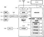
図1は,本発明の一実施形態に係るテレビジョン受像システム100を表すブロック図である。テレビジョン受像システム100は,テレビジョン受像装置110,リモコン130,アンテナ140,モニタ150,HDMIスイッチ160,機器171〜173を有する。Hereinafter, embodiments of the present invention will be described in detail with reference to the drawings.
FIG. 1 is a block diagram showing a
テレビジョン受像装置110は,テレビジョン映像を受信し,モニタ150上に表示させる装置であり,チューナ111,録画部112,映像処理部113,制御部114,HDMI接続部115,IR受光部116を有する。 The
チューナ111は,アンテナ140で受信した電波から適宜のテレビジョン放送番組(例えば,ディジタル放送)を選択(選局)する。
録画部112は,チューナ111で選択されたテレビジョン放送を録画する。The tuner 111 selects (selects) an appropriate television broadcast program (for example, digital broadcast) from the radio wave received by the
The
映像処理部113は,チューナ111,録画部112,機器171〜173の間での映像信号の入出力を仲介すると共に,これらから出力される映像信号をモニタ150で表示可能な信号に変換する(信号処理)。 The
制御部114は,テレビジョン受像装置110を制御する制御部であり,CPU(Central Processing Unit:中央制御装置),記憶装置(例えば,半導体メモリ)の組み合わせから構成することができる。制御部114は,映像処理部113に映像制御信号およびGUI表示信号を出力する。映像制御信号は,映像処理部113でのテレビジョン放送信号の処理を制御するための信号である。GUI表示信号は,ユーザが情報を入力するための画像(GUI画像)をモニタ150上に表示させるための信号である。 The
制御部114は,HDMI接続部115とCEC制御線で接続され,HDMI−CEC制御信号(コマンド(命令))を出力することで,HDMIスイッチ160,機器171〜173を制御したり,これらの状態を確認したりすることができる。
制御部114は,IR受光部116からのユーザの入力情報を受け付ける。The
The
制御部114は,機器接続情報記憶部121,状態確認部122,切替処理部123,表示制御部124を有する。 The
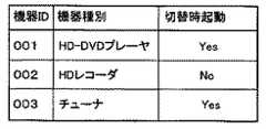
機器接続情報記憶部121は,テレビジョン受像装置110に接続されている機器171〜173の情報を記憶する。図2は,機器接続情報記憶部121の記憶内容の一例を表す模式図である。 The device connection
「機器のID(識別子:Identifier)」,「機器の種別」,「切替時起動」が対応して表される。「機器の識別子」の欄には,機器171〜173を互いに識別する識別情報,例えば,機器171〜173のアドレスが挿入される。「機器の種別」の欄には,機器171〜173の種別,例えば,プレーヤ,レコーダ,チューナの何れであるかを表す情報が挿入される。「切替時起動」の欄には,映像信号を入力する機器171〜173を切り替える際に,待機状態の機器171〜173を起動(電源を投入)するか否かを表す切替時起動情報が挿入される。 "Device ID (identifier: Identifier)", "Device type", and "Start-up at switching" are shown correspondingly. In the “device identifier” column, identification information for identifying the
これらの内,「機器の識別子」,「機器の種別」は,機器171〜173をHDMIスイッチ160に接続する際の接続処理の結果として,機器接続情報記憶部121に記憶される。また,「切替時起動」は,後述の機器の設定入力の結果として,機器接続情報記憶部121に記憶される。即ち,図2は,機器の設定入力後での機器接続情報記憶部121の記憶内容を表す。機器の設定入力前では,「切替時起動」の欄には,未設定であることを表す「−」が挿入される。
なお,図2には示されていないが,HDMIスイッチ160も広義の機器であり,機器接続情報記憶部121に識別子等が記憶されているものとする。Among these, “device identifier” and “device type” are stored in the device connection
Although not shown in FIG. 2, it is assumed that the
状態確認部122は,接続されている機器171〜173が起動状態,待機状態の何れであるかを確認する。即ち,状態確認部122は,機器171〜173に状態(電源状態)の通知を指示するコマンドを送信し,機器171〜173からの応答コマンド(電源状態を通知するコマンド)を受信する。この結果,状態確認部122は,機器171〜173の状態を確認できる。 The
切替処理部123は,機器171〜173からの映像信号の入力を切り替える。この切替のため,切替処理部123は,切替コマンドを送信する。即ち,切替処理部123は,コマンドを送信する送信部として機能する。この切替コマンドは以下の(1)〜(3)を指示する。 The switching processing unit 123 switches input of video signals from the
(1)HDMIスイッチ160に,映像信号の入力元の切替を指示する。即ち,切替コマンドは,機器171〜173の何れかを新たな入力元として選択するかを表わす。切替コマンドを受信したHDMIスイッチ160は,指定された入力元からの映像信号がテレビジョン受像装置110へと出力されるように,機器側端子と装置側端子の接続関係を切り替える。(1) Instruct the
(2)入力元として選択された機器171〜173に,映像信号の出力を指示する。この指示に応じて,選択された機器171〜173から映像信号が出力される。(2) Instructing the
(3)入力先として選択された機器171〜173に,待機状態の場合の起動を指示する。この指示に応じて,選択された機器171〜173が待機状態の場合,その機器171〜173が起動する。このため,後述のように,この切替コマンドの送信に先だって,状態確認部122によって機器171〜173の状態が確認される。(3) Instruct the
表示制御部124は,機器選択画面および起動選択画面をモニタ150に表示させる。機器選択画面は,映像信号の入力元として選択する機器171〜173を選択するためのGUI画面である。起動選択画面は,切替時に待機状態の機器171〜173を起動するか否か(起動の有無)を選択(切替時起動情報を設定)するためのGUI画面である。 The display control unit 124 causes the
HDMI接続部115は,HDMI規格に対応する機器と接続するためのインタフェースである。HDMI規格に対応する機器として,HDMIスイッチ160,機器171〜173が直接的あるいは間接的に接続される。HDMI接続部115は機器171〜173と映像処理部113間での映像信号の入出力を仲介する。また,HDMI接続部115は,HDMIスイッチ160,機器171〜173と制御部114間でのコマンドの入出力を仲介する。 The
IR受光部116は,ユーザの操作によるリモコン130からの赤外線(IR)発光を受光し,信号に変換して制御部114に出力する。
リモコン130は,ユーザの操作によって赤外線を発光し,テレビジョン受像装置110を制御するための遠隔制御装置である。
アンテナ140は,テレビジョン放送を含む電波を受信するためのものである。
モニタ150は,テレビジュン放送を表示するための表示装置,例えば,液晶表示装置,プラズマディスプレイである。The IR
The
The
The
HDMIスイッチ160は,複数の機器側端子,単一の装置側端子を有し,装置側端子に対して機器側端子を切り替え接続する。機器側端子,装置側端子に機器171〜173およびHDMI接続部115(テレビジョン受像装置110)が接続される。制御部114からの切替コマンドにより,HDMIスイッチ160は,複数の機器171〜173を選択してHDMI接続部115に接続する。その結果,テレビジョン受像装置110への映像信号の入力元が切り替えられる。この切替のため,HDMIスイッチ160は,機器171〜173の識別子と機器側端子との対応関係を表すテーブルを記憶する記憶部を有する。
なお,ここでは,HDMIスイッチ160に3つの機器171〜173が接続されているが,この個数は適宜に変更できる。The
Here, three
機器171〜173は,映像信号を入力または出力する機器,例えば,HD−DVDプレーヤ,HD(ハードディスク)レコーダ,チューナである。機器171〜173は,制御部114からのコマンドにより,起動および映像出力等が制御される。 The
これらの機器171〜173は,ON状態(起動状態),OFF状態(待機状態)の2通りの動作状態を取る。例えば,機器171〜173のプラグを電源コンセントに接続すると,OFF状態となり,電源スイッチを押すことで,ON状態に移行する。 These
これら2つの状態は電源の状態,即ち,機器171〜173の消費電力と対応している。ON状態(起動状態)では,機器171〜173の全体で電力が消費され,本来の機能(例えば,再生機能,録画機能等)が発揮される。一方,OFF状態(待機状態)では,機器171〜173の一部,例えば,HDMIインタフェースのみで電力が消費され,主要部には電力が供給されない。このため,待機状態の機器171〜173は,本来の機能(例えば,再生機能,録画機能等)を発揮されない。但し,待機状態の機器171〜173でも,HDMI−CECのコマンドにより,機器171〜173の起動,状態の確認等が可能である。 These two states correspond to the power state, that is, the power consumption of the
(テレビジョン受像システム100の動作)
図3は,テレビジョン受像システム100の動作手順の一例を表すフロー図である。
(1)機器の接続(ステップS11)
最初はHDMIスイッチ160に機器171〜173が接続されていないとする。HDMIスイッチ160に機器171〜173を接続すると,この接続が契機となって,制御部114が機器171〜173の存在を認識する。即ち,制御部114と機器171〜173との間で,コマンドがやり取りされることで,機器171〜173の識別子,機器の種別が制御部114に通知され,接続情報記憶部121に記憶される。なお,この時点では,「切替時起動」は設定されていない。(Operation of the television receiving system 100)
FIG. 3 is a flowchart showing an example of the operation procedure of the
(1) Device connection (step S11)
Initially, it is assumed that the
(2)切替時起動情報の設定(ステップS12)
ユーザがリモコン130を操作し,機器171〜173の切替時起動情報(切替時に待機状態の機器171〜173を起動するか否かを表す情報)を設定(入力)する。
図4は,切替時起動情報を入力するためのGUI画面(起動選択画面)の一例を表す図である。
機器171〜173それぞれについて,切替時に電源を投入(起動)するか否かを設定することで,接続情報記憶部121の「切替時起動」の欄に「Yes」または「No」が挿入される(図2参照)。(2) Setting of switching start information (step S12)
The user operates the
FIG. 4 is a diagram illustrating an example of a GUI screen (startup selection screen) for inputting start-up information at the time of switching.
For each of the
(3)入力元とする機器の選択(ステップS13〜S15)
1)機器選択画面の表示(ステップS13)
ユーザがリモコン130を操作することで,機器選択画面が表示される。
図5は,機器選択画面の一例を表す図である。機器選択画面は,映像信号の入力元として選択する機器を表す情報を入力するためのGUI画面である。(3) Selection of input source device (steps S13 to S15)
1) Display of device selection screen (step S13)
When the user operates the
FIG. 5 is a diagram illustrating an example of a device selection screen. The device selection screen is a GUI screen for inputting information representing a device to be selected as the video signal input source.
2)機器の状態の確認(ステップS14)
機器171〜173の状態が確認される。即ち,制御部114から機器171〜173に状態(起動状態,待機状態)の通知を指示するコマンドが送信される。これに対する応答として,機器171〜173から制御部114に状態を通知するコマンドが送信されることで,機器171〜173の状態が制御部114に通知される。2) Confirmation of device status (step S14)
The states of the
なお,この確認は,切替コマンドの送信より前であれば,異なるタイミングで行える。例えば,機器選択画面の表示(ステップ13)の前に,機器171〜173の状態を確認(ステップS14)しても良い。 Note that this confirmation can be performed at different timings before the transmission of the switching command. For example, the state of the
3)選択機器の入力(ステップS15)
ユーザがリモコン130を操作することで,機器選択画面に表される機器171〜173のリストから機器171〜173の何れかが選択される。3) Input of selected device (step S15)
When the user operates the
(4)機器への切替コマンドの送信(ステップS16〜S21)
機器171〜173の状態等に応じて,切替コマンドの送信等がなされる。
1)選択された機器171〜173が起動状態の場合(ステップS16,S17)
起動状態の機器171〜173が選択された場合(ステップS16),選択された機器171〜173に切替コマンドが送信される(ステップS17)。この結果,切替スイッチ160が動作し,映像信号の入力元が選択された機器171〜173に切り替わる。また,選択された機器171〜173から映像信号が出力される。この結果,モニタ150に選択された機器171〜173からの映像が表示される。(4) Transmission of switch command to device (steps S16 to S21)
A switching command is transmitted according to the status of the
1) When the selected
When the activated
選択された機器171〜173が起動状態であるため,待機状態の機器171〜173を不用意に起動することが防止される。選択された機器171〜173が待機状態の場合,ステップS18において,切替時起動の設定の有無が判断される。 Since the selected
2)選択された機器171〜173が待機状態で,切替時起動情報が設定されている場合(ステップS18,S19)
この場合,切替時起動の設定に応じた処理がなされる(ステップS19)。即ち,電源を投入”する”Yes)と設定した機器171〜173に対しては,切替コマンドを送信する。この結果,切替スイッチ160が切り替わり,選択された機器171〜173が起動され,かつ映像信号が出力される。一方,電源を投入”しない”(No)と設定した機器171〜173が選択された場合,切替コマンドが送信されず,モニタ150に表示される映像は切り替わらない。2) When the selected
In this case, processing according to the setting at the time of switching is performed (step S19). That is, a switching command is transmitted to the
3)選択された機器171〜173が待機状態で,切替時起動情報が設定されていない場合(ステップS20,S21)
この場合,ユーザが機器171〜173の電源の投入の有無を選択し,その選択に応じて切替コマンドが送信される。3) When the selected
In this case, the user selects whether or not the
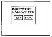
このとき,モニタ150上に起動選択画面(切替許諾画面)が表示される。
図6は,起動選択画面の一例を表す図である。起動選択画面は,機器171〜173の起動の有無(電源の投入の有無)を表す情報を入力するためのGUI画面(機器171〜173の電源を投入することの許諾を求めるためのGUI画面)である。ユーザが、”はい”を選択すると機器171〜173が起動され,モニタ150に映像が表示される。ユーザが”いいえ”を選択すると,切替コマンドは送信されず,切り替え処理は行われない。At this time, an activation selection screen (switching permission screen) is displayed on the
FIG. 6 is a diagram illustrating an example of the activation selection screen. The activation selection screen is a GUI screen for inputting information indicating whether or not the
以上のように,テレビジョン受像システム100では,テレビジョン受像装置110に接続されている機器171〜173の状態(電源状態)を確認し、機器171〜173の切り替え時に無条件で電源が投入されてしまうことを防止できる。この結果、消費電力軽減および視聴者の意図に反した電源投入防止立が可能となる。 As described above, in the
(その他の実施形態)
本発明の実施形態は上記の実施形態に限られず拡張,変更可能であり,拡張,変更した実施形態も本発明の技術的範囲に含まれる。(Other embodiments)
Embodiments of the present invention are not limited to the above-described embodiments, and can be expanded and modified. The expanded and modified embodiments are also included in the technical scope of the present invention.
100…テレビジョン受像システム,110…テレビジョン受像装置,111…チューナ,112…録画部,113…映像処理部,114…制御部,115…HDMI接続部,116…IR受光部,121…機器接続情報記憶部,130…リモコン,140…アンテナ,150…モニタ,160…HDMIスイッチ,171-173…機器 DESCRIPTION OF
Claims (7)
Translated fromJapanese前記記憶される識別情報に基づいて,映像信号を出力する機器を選択するための機器選択画面を表示させる第1の表示制御部と,
機器が起動状態,待機状態の何れであるかを確認する確認部と,
前記機器選択画面を用いて選択された機器が起動状態であることが確認された場合,前記選択された機器に映像信号の出力を指示するコマンドを送信する第1の送信部と,
を具備することを特徴とするテレビジョン受像装置。A storage unit for storing identification information for identifying a device that outputs a video signal;
A first display control unit for displaying a device selection screen for selecting a device that outputs a video signal based on the stored identification information;
A confirmation unit for confirming whether the device is in the active state or the standby state;
A first transmission unit that transmits a command instructing the selected device to output a video signal when it is confirmed that the device selected using the device selection screen is in an activated state;
A television receiver characterized by comprising:
ことを特徴とする請求項1記載のテレビジョン受像装置。The television receiver according to claim 1, wherein the command instructs a device in a standby state to start and output a video signal.
前記コマンドが,前記切替スイッチに入力元の切替を指示する
ことを特徴とする請求項1または2に記載のテレビジョン受像装置。The device is connected to a changeover switch for switching the input source of the video signal;
The television receiver according to claim 1, wherein the command instructs the changeover switch to switch an input source.
前記起動することが選択された機器に前記コマンドを送信する第2の送信部と,
をさらに具備することを特徴とする請求項1乃至3のいずれか1項に記載のテレビジョン受像装置。A second display control unit for displaying an activation selection screen for selecting whether to activate the selected device when it is confirmed that the selected device is in a standby state;
A second transmitter for transmitting the command to the device selected to be activated;
The television receiver according to claim 1, further comprising:
前記記憶される起動情報に基づいて,前記コマンドを送信するか否かを決定する決定部と,
をさらに具備することを特徴とする請求項1乃至4のいずれか1項に記載のテレビジョン受像装置。The storage unit further stores activation information indicating whether to activate the device when the device represented by the identification information is in a standby state;
A determination unit that determines whether to transmit the command based on the stored activation information;
The television receiver according to claim 1, further comprising:
をさらに具備することを特徴とする請求項1乃至5のいずれか1項に記載のテレビジョン受像装置。Tuners for selecting broadcast programs,
The television receiver according to claim 1, further comprising:
機器が起動状態,待機状態の何れであるかを確認するステップと,
前記機器選択画面を用いて選択された機器が起動状態であることが確認された場合,前記選択された機器に映像信号の出力を指示するコマンドを送信するステップと,
を具備することを特徴とする機器制御方法。Displaying a device selection screen for selecting a device that outputs a video signal based on the storage content of a storage unit that stores identification information for identifying a device that outputs a video signal;
A step of confirming whether the device is in an active state or a standby state;
When it is confirmed that the device selected using the device selection screen is in an activated state, a command for instructing the selected device to output a video signal;
The apparatus control method characterized by comprising.
Priority Applications (3)
| Application Number | Priority Date | Filing Date | Title |
|---|---|---|---|
| JP2007145643AJP2008301232A (en) | 2007-05-31 | 2007-05-31 | Television receiver and device control method |
| US12/052,870US20080297655A1 (en) | 2007-05-31 | 2008-03-21 | Television receiving apparatus and device control method |
| CN200810088825.8ACN101316333A (en) | 2007-05-31 | 2008-03-28 | Television receiving equipment and device control method |
Applications Claiming Priority (1)
| Application Number | Priority Date | Filing Date | Title |
|---|---|---|---|
| JP2007145643AJP2008301232A (en) | 2007-05-31 | 2007-05-31 | Television receiver and device control method |
Publications (1)
| Publication Number | Publication Date |
|---|---|
| JP2008301232Atrue JP2008301232A (en) | 2008-12-11 |
Family
ID=40087698
Family Applications (1)
| Application Number | Title | Priority Date | Filing Date |
|---|---|---|---|
| JP2007145643AWithdrawnJP2008301232A (en) | 2007-05-31 | 2007-05-31 | Television receiver and device control method |
Country Status (3)
| Country | Link |
|---|---|
| US (1) | US20080297655A1 (en) |
| JP (1) | JP2008301232A (en) |
| CN (1) | CN101316333A (en) |
Cited By (3)
| Publication number | Priority date | Publication date | Assignee | Title |
|---|---|---|---|---|
| US8207751B2 (en) | 2009-04-16 | 2012-06-26 | Kabushiki Kaisha Toshiba | Receiver which receives video information |
| JPWO2013168288A1 (en)* | 2012-05-11 | 2015-12-24 | パイオニアデジタルデザインアンドマニュファクチャリング株式会社 | Relay device |
| WO2018167948A1 (en)* | 2017-03-17 | 2018-09-20 | ヤマハ株式会社 | Content playback device, method, and content playback system |
Families Citing this family (11)
| Publication number | Priority date | Publication date | Assignee | Title |
|---|---|---|---|---|
| CN101138202B (en)* | 2005-03-10 | 2012-07-18 | 松下电器产业株式会社 | Communication connection method and device |
| US20090248909A1 (en)* | 2008-03-26 | 2009-10-01 | Sony Corporation | Method and Apparatus for Simulating Consumer Electronic Control Functionality for Devices |
| US8860893B2 (en)* | 2008-08-22 | 2014-10-14 | Sony Corporation | DTV with detachable HDMI inputs |
| TWI446176B (en)* | 2009-10-20 | 2014-07-21 | Wistron Corp | Detection method and detection device and multimedia device |
| JP5277220B2 (en)* | 2010-08-16 | 2013-08-28 | 株式会社エヌ・ティ・ティ・ドコモ | Mobile communication method and mobile station |
| US9529243B2 (en) | 2011-10-25 | 2016-12-27 | Nippon Electric Glass Co., Ltd. | Liquid crystal element and cell for liquid crystal element |
| KR20160041243A (en)* | 2014-10-07 | 2016-04-18 | 삼성전자주식회사 | Display apparatus, display system, and method for display |
| WO2016199346A1 (en)* | 2015-06-11 | 2016-12-15 | ソニー株式会社 | Information processing method, program, information processing device, and information processing system |
| CN105916016A (en)* | 2016-04-11 | 2016-08-31 | 联想(北京)有限公司 | Information processing method and electronic device |
| EP3331248A1 (en)* | 2016-11-30 | 2018-06-06 | Thomson Licensing | Smart standby with multiple devices |
| JP7246913B2 (en)* | 2018-12-18 | 2023-03-28 | シャープ株式会社 | Information processing system, information processing device, and information processing method |
Family Cites Families (4)
| Publication number | Priority date | Publication date | Assignee | Title |
|---|---|---|---|---|
| US5598523A (en)* | 1994-03-31 | 1997-01-28 | Panasonic Technologies, Inc. | Method and system for displayed menu activation using a matching distinctive arrangement of keypad actuators |
| US6993606B1 (en)* | 1999-11-18 | 2006-01-31 | Sony Corporation | Communication method and communication apparatus for data communication between devices connected by a network |
| JP4369214B2 (en)* | 2002-12-11 | 2009-11-18 | パナソニック株式会社 | AV system |
| US7983614B2 (en)* | 2006-09-29 | 2011-07-19 | Sony Ericsson Mobile Communications Ab | Handover for audio and video playback devices |
- 2007
- 2007-05-31JPJP2007145643Apatent/JP2008301232A/ennot_activeWithdrawn
- 2008
- 2008-03-21USUS12/052,870patent/US20080297655A1/ennot_activeAbandoned
- 2008-03-28CNCN200810088825.8Apatent/CN101316333A/enactivePending
Cited By (4)
| Publication number | Priority date | Publication date | Assignee | Title |
|---|---|---|---|---|
| US8207751B2 (en) | 2009-04-16 | 2012-06-26 | Kabushiki Kaisha Toshiba | Receiver which receives video information |
| JPWO2013168288A1 (en)* | 2012-05-11 | 2015-12-24 | パイオニアデジタルデザインアンドマニュファクチャリング株式会社 | Relay device |
| WO2018167948A1 (en)* | 2017-03-17 | 2018-09-20 | ヤマハ株式会社 | Content playback device, method, and content playback system |
| JPWO2018167948A1 (en)* | 2017-03-17 | 2019-06-27 | ヤマハ株式会社 | Content reproduction apparatus, method, and content reproduction system |
Also Published As
| Publication number | Publication date |
|---|---|
| CN101316333A (en) | 2008-12-03 |
| US20080297655A1 (en) | 2008-12-04 |
Similar Documents
| Publication | Publication Date | Title |
|---|---|---|
| JP2008301232A (en) | Television receiver and device control method | |
| US20230421833A1 (en) | Video display apparatus and terminal apparatus | |
| US11012733B2 (en) | Device controller, computer readable storage medium, and remote control system | |
| JPWO2009101804A1 (en) | Power saving system | |
| JP2009211163A (en) | Electronic equipment and display control method | |
| JP2010206441A (en) | Television receiver | |
| JP2009141537A (en) | Display system, display device, and repeater device | |
| JP4664448B2 (en) | Electronic device connectable with external device and optical disk playback device | |
| US8253857B2 (en) | Broadcasting receiving apparatus | |
| JP2008141504A (en) | Electrical equipment | |
| US7934246B2 (en) | Broadcast receiver | |
| JP2008219392A (en) | Television receiver, digital broadcast signal processing device | |
| KR101300949B1 (en) | Control method of external A/V devices connected to Display | |
| JP5171428B2 (en) | Electronics | |
| JP2007013930A (en) | Remote controller and remote control method | |
| JP2007013929A (en) | Remote controller for remote control, equipment operating system and remote control method for remote control | |
| JP5878559B2 (en) | Transmission device, reception device, and transmission / reception method | |
| KR101018483B1 (en) | Digital instrument systems | |
| JP2011086992A (en) | Video display system | |
| JP5294552B2 (en) | Video display device, recording / playback device | |
| JP2013247539A (en) | Display device, display method, and display device control program | |
| JP5197650B2 (en) | Electronic device and display control method | |
| JP5736639B2 (en) | Recording equipment | |
| JP2013126204A (en) | Transmitter, receiver and transmission/reception method | |
| JP5157423B2 (en) | Recording control method, recording system, viewing device, and recording device |
Legal Events
| Date | Code | Title | Description |
|---|---|---|---|
| A300 | Application deemed to be withdrawn because no request for examination was validly filed | Free format text:JAPANESE INTERMEDIATE CODE: A300 Effective date:20100803 |