JP2008293747A - Communication relay device and relay connector unit - Google Patents
Communication relay device and relay connector unitDownload PDFInfo
- Publication number
- JP2008293747A JP2008293747AJP2007136935AJP2007136935AJP2008293747AJP 2008293747 AJP2008293747 AJP 2008293747AJP 2007136935 AJP2007136935 AJP 2007136935AJP 2007136935 AJP2007136935 AJP 2007136935AJP 2008293747 AJP2008293747 AJP 2008293747A
- Authority
- JP
- Japan
- Prior art keywords
- communication
- connection
- communication address
- conduction
- unit
- Prior art date
- Legal status (The legal status is an assumption and is not a legal conclusion. Google has not performed a legal analysis and makes no representation as to the accuracy of the status listed.)
- Abandoned
Links
- 230000006870functionEffects0.000description10
- 230000013011matingEffects0.000description6
- 230000004308accommodationEffects0.000description4
- 238000010586diagramMethods0.000description4
- 229920003002synthetic resinPolymers0.000description4
- 239000000057synthetic resinSubstances0.000description4
- 238000012423maintenanceMethods0.000description3
- 230000002159abnormal effectEffects0.000description2
- 230000005856abnormalityEffects0.000description2
- 230000000694effectsEffects0.000description2
- 238000004519manufacturing processMethods0.000description2
- 241000257465EchinoideaSpecies0.000description1
- 239000002184metalSubstances0.000description1
- 238000012986modificationMethods0.000description1
- 230000004048modificationEffects0.000description1
- 230000000149penetrating effectEffects0.000description1
- 230000000007visual effectEffects0.000description1
Images


Classifications
- H—ELECTRICITY
- H01—ELECTRIC ELEMENTS
- H01R—ELECTRICALLY-CONDUCTIVE CONNECTIONS; STRUCTURAL ASSOCIATIONS OF A PLURALITY OF MUTUALLY-INSULATED ELECTRICAL CONNECTING ELEMENTS; COUPLING DEVICES; CURRENT COLLECTORS
- H01R29/00—Coupling parts for selective co-operation with a counterpart in different ways to establish different circuits, e.g. for voltage selection, for series-parallel selection, programmable connectors
- H—ELECTRICITY
- H01—ELECTRIC ELEMENTS
- H01R—ELECTRICALLY-CONDUCTIVE CONNECTIONS; STRUCTURAL ASSOCIATIONS OF A PLURALITY OF MUTUALLY-INSULATED ELECTRICAL CONNECTING ELEMENTS; COUPLING DEVICES; CURRENT COLLECTORS
- H01R13/00—Details of coupling devices of the kinds covered by groups H01R12/70 or H01R24/00 - H01R33/00
- H01R13/64—Means for preventing incorrect coupling
- H01R13/641—Means for preventing incorrect coupling by indicating incorrect coupling; by indicating correct or full engagement
- H—ELECTRICITY
- H01—ELECTRIC ELEMENTS
- H01R—ELECTRICALLY-CONDUCTIVE CONNECTIONS; STRUCTURAL ASSOCIATIONS OF A PLURALITY OF MUTUALLY-INSULATED ELECTRICAL CONNECTING ELEMENTS; COUPLING DEVICES; CURRENT COLLECTORS
- H01R13/00—Details of coupling devices of the kinds covered by groups H01R12/70 or H01R24/00 - H01R33/00
- H01R13/66—Structural association with built-in electrical component
- H01R13/665—Structural association with built-in electrical component with built-in electronic circuit
- H—ELECTRICITY
- H01—ELECTRIC ELEMENTS
- H01R—ELECTRICALLY-CONDUCTIVE CONNECTIONS; STRUCTURAL ASSOCIATIONS OF A PLURALITY OF MUTUALLY-INSULATED ELECTRICAL CONNECTING ELEMENTS; COUPLING DEVICES; CURRENT COLLECTORS
- H01R12/00—Structural associations of a plurality of mutually-insulated electrical connecting elements, specially adapted for printed circuits, e.g. printed circuit boards [PCB], flat or ribbon cables, or like generally planar structures, e.g. terminal strips, terminal blocks; Coupling devices specially adapted for printed circuits, flat or ribbon cables, or like generally planar structures; Terminals specially adapted for contact with, or insertion into, printed circuits, flat or ribbon cables, or like generally planar structures
- H01R12/50—Fixed connections
- H01R12/59—Fixed connections for flexible printed circuits, flat or ribbon cables or like structures
- H01R12/65—Fixed connections for flexible printed circuits, flat or ribbon cables or like structures characterised by the terminal
- H01R12/67—Fixed connections for flexible printed circuits, flat or ribbon cables or like structures characterised by the terminal insulation penetrating terminals
- H01R12/675—Fixed connections for flexible printed circuits, flat or ribbon cables or like structures characterised by the terminal insulation penetrating terminals with contacts having at least a slotted plate for penetration of cable insulation, e.g. insulation displacement contacts for round conductor flat cables
- H—ELECTRICITY
- H01—ELECTRIC ELEMENTS
- H01R—ELECTRICALLY-CONDUCTIVE CONNECTIONS; STRUCTURAL ASSOCIATIONS OF A PLURALITY OF MUTUALLY-INSULATED ELECTRICAL CONNECTING ELEMENTS; COUPLING DEVICES; CURRENT COLLECTORS
- H01R12/00—Structural associations of a plurality of mutually-insulated electrical connecting elements, specially adapted for printed circuits, e.g. printed circuit boards [PCB], flat or ribbon cables, or like generally planar structures, e.g. terminal strips, terminal blocks; Coupling devices specially adapted for printed circuits, flat or ribbon cables, or like generally planar structures; Terminals specially adapted for contact with, or insertion into, printed circuits, flat or ribbon cables, or like generally planar structures
- H01R12/70—Coupling devices
- H01R12/77—Coupling devices for flexible printed circuits, flat or ribbon cables or like structures
- H01R12/777—Coupling parts carrying pins, blades or analogous contacts
Landscapes
- Engineering & Computer Science (AREA)
- Microelectronics & Electronic Packaging (AREA)
- Details Of Connecting Devices For Male And Female Coupling (AREA)
- Selective Calling Equipment (AREA)
- Connections By Means Of Piercing Elements, Nuts, Or Screws (AREA)
Abstract
Translated fromJapaneseDescription
Translated fromJapanese本発明は、1台の電子制御装置で複数の電子機器を制御するための通信中継装置及び中継コネクタユニットに関するものである。 The present invention relates to a communication relay device and a relay connector unit for controlling a plurality of electronic devices with a single electronic control device.
乗用車、貨物車等の車両には、エアコンやワイパー、パワーウィンドウなどを構成するモータなどの多種多様な電気機器が搭載されている。前記電気機器に電力や制御信号などを伝えるために、ワイヤハーネスを配索している。ワイヤハーネスは、複数の電線と、電線の端末に接続される端子金具を収容するコネクタとを備えている。電線は、導電性の芯線と、該芯線を被覆する絶縁性の被覆部と、を備えた所謂被覆電線である。 Vehicles such as passenger cars and freight cars are equipped with a wide variety of electric devices such as motors that constitute air conditioners, wipers, and power windows. A wire harness is routed in order to transmit electric power, a control signal, and the like to the electric device. The wire harness includes a plurality of electric wires and a connector that accommodates a terminal fitting connected to an end of the electric wire. The electric wire is a so-called covered electric wire including a conductive core wire and an insulating covering portion that covers the core wire.
前述したワイヤハーネスのコネクタとして、各種のアクチュエータなどの電子機器とコンピュータなどの電子制御装置(ECU:Electronic Control Unit)とをデータ通信によるネットワークで接続するために、回路素子などを内蔵した機能内蔵コネクタ(例えば、特許文献1参照)が用いられている。この種の機能内蔵コネクタは、回路素子などを実装したリードフレームをハウジング内に内蔵している。 Built-in connector with built-in circuit elements to connect electronic devices such as various actuators and electronic control units (ECU: Electronic Control Unit) such as computers via a network by data communication as connectors for the wire harness described above (For example, refer to Patent Document 1). This type of built-in connector has a lead frame in which a circuit element or the like is mounted in a housing.
特許文献1に示す機能内蔵コネクタは、通信アドレス設定用の少なくとも1つの接続部と、除去可能な状態でグランド電位に設定されて設けられ、対応する各接続部に電気的に接続される少なくとも1つの電極部とが設けられ、CPUが各接続部の電位レベルに基づいて通信アドレスの設定を受け付ける。そして、設定すべき通信アドレスに応じて電極部を除去し、電極部と導通される接続部を決定することにより、アドレス設定を行っていた。
複数の機能内蔵コネクタを共通の通信線に接続して通信を行う場合、通信アドレスやID(identification data)を、上述したように設定可能な構成を設ける、予め内蔵回路に設定する、不揮発性メモリ等に予め記憶する等を行うことで、各機能内蔵コネクタ同士の信号の授受を可能としていた。しかしながら、機能内蔵コネクタは個別にID等を設定する必要があり、外観が同じものだと誤接続される可能性があったため、通信システムにおける機能内蔵コネクタの形状、外見を異ならせることで、誤組み付けの防止が図られている。また、機能内蔵コネクタの形状等を同一又は類似させてしまうと、組み付け時に他の機能内蔵コネクタと区別ができないため、製造不良になる危険性もあった。そのため、機能内蔵コネクタの形状を同一にすることができないという問題があり、この問題が解消できないために、機能内蔵コネクタの種類の減少及び共通化を図ることができず、部品のコストダウンを図ることができなかった。 When communication is performed by connecting a plurality of function built-in connectors to a common communication line, a non-volatile memory in which a communication address and ID (identification data) can be set as described above is set in a built-in circuit in advance. For example, it is possible to transmit / receive signals between the connectors with built-in functions. However, it is necessary to set the ID etc. individually for the built-in function connector, and if it has the same appearance, it may be misconnected. Assembly is prevented. Further, if the shape or the like of the function built-in connector is the same or similar, there is a risk of manufacturing failure because it cannot be distinguished from other function built-in connectors at the time of assembly. For this reason, there is a problem that the shapes of the function built-in connectors cannot be made the same, and since this problem cannot be solved, the types of function built-in connectors cannot be reduced and shared, and the cost of parts can be reduced. I couldn't.
よって本発明は、上述した問題点に鑑み、誤組み付けを防止し且つ共通化を図ることができる通信中継装置及び中継コネクタユニットを提供することを課題としている。 Therefore, in view of the above-described problems, an object of the present invention is to provide a communication relay device and a relay connector unit that can prevent misassembly and can be shared.
上記課題を解決するため本発明によりなされた請求項1記載の通信中継装置は、電子制御装置に接続された第1ワイヤハーネスが接続される第1接続手段と、複数の電子機器に接続された第2ワイヤハーネスが接続される第2接続手段と、複数の接続部における導通の有無に基づいた導通パターンで前記電子制御装置との通信アドレスを設定する通信アドレス設定手段と、前記第1接続手段及び前記第2接続手段に電気的に接続し且つ前記通信アドレス設定手段が設定した通信アドレスに基づいて、前記電子制御装置と前記複数の電子機器との間の通信を中継する通信中継手段と、を有する通信中継装置において、前記通信アドレス設定手段が、前記複数の接続部の導通の有無を外部から目視でき且つ前記導通パターンを設定又は変更できるように形成されていることを特徴とする。 In order to solve the above-mentioned problem, the communication relay device according to
上記請求項1に記載した本発明の通信中継装置によれば、第1接続手段に第1ワイヤハーネスを接続した後に複数の接続部の導通パターンを設定又は変更でき、且つ、その導通パターンを外部から目視して確認することができる。 According to the communication relay device of the present invention described in
請求項2記載の通信中継装置は、前記通信アドレス設定手段が、前記接続部に着脱自在に設けられ且つ当該接続部の導通の有無を設定又は変更する導通端子を有することを特徴とする。 The communication relay device according to claim 2 is characterized in that the communication address setting means has a continuity terminal that is detachably provided in the connection portion and sets or changes the continuity of the connection portion.
上記請求項2に記載した本発明の通信中継装置によれば、接続部の導通の有無を導通端子によって設定又は変更でき、しかも、その導通端子の有無を目視することで、導通パターンを確認することができる。 According to the communication relay device of the present invention as set forth in claim 2, the presence / absence of continuity of the connecting portion can be set or changed by the continuity terminal, and the continuity pattern is confirmed by visually observing the presence / absence of the continuity terminal. be able to.
上記課題を解決するため本発明によりなされた請求項3記載の中継コネクタユニットは、請求項1又は2に記載の通信中継装置と、前記第1ワイヤハーネス及び前記第2ワイヤハーネスとの電気的な接続が可能なように前記通信中継装置を収容するハウジングと、を有する中継コネクタユニットにおいて、前記ハウジングが、前記通信中継装置の通信アドレス設定手段を外部から目視可能なように露出させる露出手段を有することを特徴とする。 The relay connector unit according to claim 3, which is made according to the present invention to solve the above-described problem, is an electrical connection between the communication relay device according to
上記請求項3に記載した本発明の中継コネクタユニットによれば、通信中継装置はハウジング内に収容されると、露出手段によって外部から目視可能なようにその通信アドレス設定手段を露出させることができる。 According to the relay connector unit of the present invention described in claim 3, when the communication relay device is accommodated in the housing, the communication address setting means can be exposed by the exposure means so that it can be visually recognized from the outside. .
以上説明したように請求項1、3に記載した本発明の通信中継装置及び中継コネクタユニットによれば、第1接続手段に第1ワイヤハーネスを接続するときやその後等に複数の接続部の導通パターンを設定又は変更でき、且つ、その導通パターンを外部から目視して確認することができることから、第1ワイヤハーネスを組み付ける前は複数の通信中継装置を共通化することができるため、製造コストを抑えることができる。また、導通パターンを外部から目視にて確認することができるため、組み付け作業性を向上でき、且つ、誤組み付け等による異常発生を防止することができる。従って、誤組み付けを防止し且つ共通化を図ることができる。 As described above, according to the communication relay device and the relay connector unit of the present invention described in
請求項2に記載の発明によれば、請求項1に記載の発明の効果に加え、通信アドレス設定手段における接続部の導通の有無を導通端子によって設定可能とし、しかも、その導通端子の有無を目視できるようにしたことから、組み付け時に通信アドレスの設定に誤りが生じても、各導通パターンを目視により確認して設定の異常箇所を特定し、導通パターンの変更に再利用することができるため、製造性及びメンテナンス性を向上することができる。 According to the invention described in claim 2, in addition to the effect of the invention described in
本発明の一実施形態にかかる通信中継装置及び中継コネクタユニットを、図1乃至図11を参照して説明する。 A communication relay device and a relay connector unit according to an embodiment of the present invention will be described with reference to FIGS.
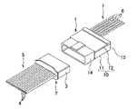
図1乃至図3において、中継コネクタユニット1は、相手方のコネクタ2と嵌合する。相手方のコネクタ2は、コネクタハウジング3と、図示しない端子金具とを備えている。コネクタハウジング3は、絶縁性の合成樹脂で構成され、扁平な箱状に形成されている。コネクタハウジング3は、端子金具を収容する。端子金具は、複数設けられ、それぞれが芯線と該芯線を被覆した被覆部とを有した複数の電線4からなる第1ワイヤハーネス5が取り付けられる。端子金具は、取り付けられた電線4の芯線と電気的に接続する。 1 to 3, the
中継コネクタユニット1は、ハウジング10と、該ハウジング10に収容され通信中継装置20と、を有している。ハウジング10は、扁平な箱状に形成され、かつユニットハウジング11と、カバー部12と、電線保持部13とを有している。 The
ユニットハウジング11は、絶縁性の合成樹脂で構成され、筒状のフード部14と、該フード部14に連なった収容室15とを一体に備えている。フード部14は、内側に相手方のコネクタ2のコネクタハウジング3が進入して、当該相手方のコネクタ2と嵌合する。収容室15は、断面コ字形に形成されて、図1中の上方に開口16が設けられている。 The
カバー部12は、絶縁性の合成樹脂で構成され、平板状に形成されている。カバー部12は、ユニットハウジング11に取り付けられる。カバー部12は、ユニットハウジング11に取り付けられると、前述した開口16を塞ぐ。 The
電線保持部13は、カバー部12に設けられた複数の電線収容溝(図示せず)を備えている。該電線収容溝は、間隔をあけて複数設けられており、内側に電線15を通して、当該電線15を保持する。電線を保持する手段として、電線収容溝の径を電線の径によりも若干小さく形成する他、電線収容溝に電線の抜け止めをする為の係止突起を設ける等が用いられる。 The electric
ハウジング10は、ユニットハウジング11とカバー部12との間に通信中継装置20を位置付けて、当該通信中継装置20を収容する。そして、電線保持部13は、複数の電線収容溝のうち、カバー部12の両側に位置する二つの電線収容溝に夫々一本の電線15を保持して、当該電線15をハウジング10内でUターンさせ、かつ前記一本の電線15を保持した電線収容溝以外の二つの電線収容溝に電線15を保持しているとともに、残りの電線収容溝14に各々電線15を一本ずつ保持させているが、端子を配列及びUターンさせるなどの取り回しについては回路構成によって適宜設定される。 The
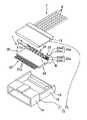
通信中継装置20は、図1乃至図5に示すように、電子制御装置30に接続された第1ワイヤハーネス7が接続される第1接続手段21と、複数の電子機器40に接続された第2ワイヤハーネス5が接続される第2接続手段22と、複数の接続部23aにおける導通の有無に基づいた導通パターンで前記電子制御装置30との通信アドレスを設定する通信アドレス設定手段23と、前記第1接続手段21及び前記第2接続手段22に電気的に接続し且つ前記通信アドレス設定手段23が設定した通信アドレスに基づいて、前記電子制御装置30と前記複数の電子機器40との間の通信を中継する通信中継手段24と、を有している。 As shown in FIGS. 1 to 5, the
第1接続手段21は、複数(図1中では6つ)の圧接端子21aを有している。圧接端子21aは、平行部21bと、立設部21cとを一体に有している。平行部23は、帯板状に形成され、かつ両表面が通信中継手段24の両表面と同一平面上に設けられている。複数の圧接端子20の平行部23は、互いに平行に配置されている。また、複数の圧接端子20の平行部23は、通信中継手段24と間隔をあけて配置されている。 The first connection means 21 has a plurality (six in FIG. 1) of
立設部21cは、圧接端子21aの平行部21bの通信中継手段24から離れた側の端から立設している。立設部21cの両表面は、平行部23の両表面に対して直交している。立設部21cは、圧接端子20の幅方向即ち複数の圧接端子20同士が並ぶ方向に沿って互いに間隔をあけた一対の圧接刃25を有している。圧接刃25は、互いの間に電線15を挟みこむとともに、当該電線15の被覆部を切り込んで、該電線15の芯線と接触する。 The standing
第2接続手段22は、導電性の金属で構成された複数のリードフレーム22aを有している。複数のリードフレーム22aは、互いに並行に通信中継手段24の縁部から突出し、且つ、所定の間隔をあけた状態で配置されている。 The second connecting
通信アドレス設定手段23は、図1に示すように、第1接続手段21の平行部23bと平行且つ通信中継手段24の側縁部から外部に向かって突出した状態で、外部からの目視が可能なように通信中継手段24に一体に形成されている。通信アドレス設定手段23は、図1及び図4に示すように、複数(図中では3つ)の接続部23aと、連結部23bと、を有し、それらを導通部材によって一体に形成している。接続部23aは、帯板状に形成され、その一端が通信中継手段24の設定端子24a1〜3に電気的に接続され、他方が連結部23bに一体に繋がっている。複数の接続部23aは、接続部23a同士が並ぶ方向に沿って互いに間隔をあけた状態で配置されている。 As shown in FIG. 1, the communication address setting means 23 is visible from the outside while being parallel to the
なお、本実施形態では、3つの連結部23bを設けることで、2進数の0〜7を通信アドレスとして設定する場合について説明するが、それ以上の値を通信アドレスとして設定する場合は、接続部23aを4つ以上設けることで対応することができる。 In this embodiment, the case where binary numbers 0 to 7 are set as communication addresses by providing three connecting
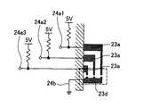
連結部23bは、コの字状の帯板状に形成されており、その端部23cが通信中継手段24のグランド線24bと電気的に接続されている。即ち、図4に示すように、全ての接続部23aが存在する場合、各接続部23aには所定の電圧(例えば、5V)が印加されている。そして、各接続部23aは、グランド線24bを介して接地されることで、電位がローレベルに保持されることになる。即ち、通信中継手段24は、接続部23aが存在する場合、設定端子24a1〜3はローレベルとして検出することになる。 The connecting
また、接続部23aが切断等により除去された場合、そこは連結部23bを介してグランド線24bに導通されなくなるため、電位がハイレベルに保持されることになる。即ち、通信中継手段24は、接続部23aが除去された場合、設定端子24a1〜3はハイレベルとして検出することになる。 Further, when the connecting
このように通信アドレス設定手段23は、複数の接続部23aの有無による導通パターンで、前記電子制御装置30との通信アドレスを設定することが可能で、複数の接続部23aの導通の有無を外部から目視できる構成となっている。 As described above, the communication address setting means 23 can set the communication address with the
通信中継手段24は、例えば集積回路、複数のディスクリートで構成した部品、マイクロ・プロセッサ、DSP(digital signal processor)、ASIC(application specific IC)等の任意の構成で実現することができ、例えばボンディングワイヤ等によって第1接続手段21及び第2接続手段22の連結部分と接続されている。なお、本実施形態では、ICチップ等を合成樹脂で封止し且つ扁平な箱状に形成した場合について説明する。 The communication relay means 24 can be realized by an arbitrary configuration such as an integrated circuit, a component composed of a plurality of discrete components, a micro processor, a DSP (digital signal processor), an ASIC (application specific IC), and the like. For example, the first connecting
通信中継手段24は、設定端子24a1〜3の電圧レベルから通信アドレス設定手段23の接続部23aの有無を特定し、その有無特定結果に基づいて導通パターンを特定し、該導通パターンと予め定められた通信アドレステーブルとを比較して、前記電子制御装置30との通信アドレスを特定する。なお、通信アドレステーブルは、内蔵メモリ等に記憶され、導通パターンから1つの通信アドレスを特定するためのテーブルとなっている。 The communication relay means 24 specifies the presence / absence of the
通信中継手段24は、通信アドレス設定手段23が示す通信アドレスに対応した第1情報を第1接続手段21で受信すると、該第1情報が有する回路識別データが示す第2接続手段22のリードフレーム22aから、当該第1情報を電子機器40に送信し、且つ、第2接続部42のリードフレーム22aで受信した第2情報に、当該リードフレーム22aを示す前記回路識別データと前記通信アドレスを付加して第1接続手段21から第2情報を前記電子制御装置30に送信する。 When the
このように構成した中継コネクタユニット1は、以下のように組み立てられる。まず、カバー部12に設けられた電線保持部13に電線15を保持する。そして、ハウジング10の開口16を通して、通信中継装置20をユニットハウジング11内に挿入する。このとき、通信アドレス設定手段23はカバー部12によって覆われていないため、外部から目視可能に露出しており、作業者等は複数の接続部の導通の有無を外部から目視でき且つ前記導通パターンを設定又は変更できる状態となっている。よって、本実施形態では、ユニットハウジング11の開口16が請求項中の露出手段として機能している。 The
通信アドレス設定手段23に対する設定又は変更が終了すると、カバー部12を開口16に徐々に近づける。すると、電線保持部13の電線収容溝内に保持された電線15が、対応する圧接端子21aの立設部21cの圧接刃間に徐々に挿入される。そして、カバー部12が、開口16を完全に塞いで、ユニットハウジング11に取り付けられると、電線15が圧接刃25間に圧入されて、圧接刃25は、電線15の被覆部を切り込んで、芯線と接触する。 When the setting or change for the communication address setting means 23 is completed, the
こうして、前述した構成の中継コネクタユニット1が組み立てられると、中継コネクタユニット1は相手方のコネクタ2と嵌合し、通信中継装置20の第1接続手段21には第1ワイヤハーネス7、第2接続手段22には第2ワイヤハーネス5がそれぞれ電気的に接続される。その結果、中継コネクタユニット1は、図5に示すように、第1ワイヤハーネス7を介して電子制御装置30と通信可能に接続されるとともに、電子制御装置30によって動作等が制御される複数の電子機器40と第2ワイヤハーネス5を介して通信可能に接続される。そして、通信中継手段24は通信アドレス設定手段23が設定した通信アドレスに基づいて、電子制御装置30と複数の電子機器40との間の通信を中継する。 Thus, when the
以上説明した、本発明の中継コネクタユニット1によれば、第1接続手段21に第1ワイヤハーネス7を接続するときやその後に等に複数の接続部23aの導通パターンを設定又は変更でき、且つ、その導通パターンを外部から目視して確認することができることから、第1ワイヤハーネス7を組み付ける前は複数の通信中継装置21を共通化することができるため、製造コストを抑えることができる。また、導通パターンを外部から目視にて確認することができるため、組み付け作業性を向上でき、且つ、誤組み付け等による異常発生を防止することができる。従って、誤組み付けを防止し且つ共通化を図ることができる。 According to the
上述した実施例1では、通信アドレス設定手段23の接続部23aを除去することで導通パターンを設定する場合について説明したが、実施例2では、導通端子を用いて設定又は変更を可能とする構成について説明する。なお、上述した実施例1と基本構成は同一であることから、実施例1のところで説明したものと同一あるいは相当する部分には同一符号を付してその詳細な説明は省略する。 In the above-described first embodiment, the case where the conduction pattern is set by removing the
図6に示す中継コネクタユニット1は、ハウジング10と、該ハウジング10に収容され通信中継装置20と、を有している。ハウジング10は、扁平な箱状に形成され、かつユニットハウジング11と、カバー部12と、電線保持部13とを有している。そして、通信中継装置20は、第1接続手段21と、第2接続手段22と、通信アドレス設定手段23と、通信中継手段24と、を有している。 The
通信アドレス設定手段23は、図6に示すように、第1接続手段21の平行部23bと平行且つ通信中継手段24の側縁部から外部に向かって突出した状態で、外部からの目視が可能なように通信中継手段24に一体に形成されている。通信アドレス設定手段23は、図6乃至図8に示すように、複数(図中では3つ)の接続部23aと、接地部23dと、複数種類(図中では3種類)の導通端子23eと、を有し、それらは導通部材によって形成している。 As shown in FIG. 6, the communication address setting means 23 is visible from the outside in a state of being parallel to the
接続部23aは、帯板状に形成され、その一端が通信中継手段24の設定端子24a1〜3に電気的に接続されている。接続部23aは、基部23a1と、取付部23a2と、を一体に有している。基部23a1は、帯板状に形成され、かつ両表面が通信中継手段24の両表面と同一平面上に設けられている。複数の基部23a1は、互いに平行に所定の間隔を開けて配置されている。 The
取付部23a2は、基部23a1の通信中継手段24から離れた側の端から立設している。取付部23a2の両表面は、基部23a1の両表面に対して直交している。取付部23a2は、導通端子23eを取り付けて保持するのに十分な長さとなっている。そして、接地部23dは、接続部23aと同様に、基部23d1と、取付部23d2と、を一体に有している。そして、基部23d1及び取付部23d2は、上述した基部23a1及び取付部23a2のそれぞれと同一の構成となっている。 The attachment portion 23a2 is erected from the end of the base portion 23a1 on the side away from the communication relay means 24. Both surfaces of the attachment portion 23a2 are orthogonal to both surfaces of the base portion 23a1. The attachment portion 23a2 is long enough to attach and hold the
導通端子23eは、接地部23dが貫通する第1貫通孔23e1と、接続部23aが貫通する第2貫通孔23e2と、第1貫通孔23e1と第2貫通孔23e2を連結する連結部23e3と、を有している。第2貫通孔23e2は、通信アドレスの設定値に対応するように、接地させる接続部23aが存在する場合に対応する箇所に形成される。連結部23e3は、第1貫通孔23e1を接地部23d、また、第2貫通孔23e2を該当する接続部23aにそれぞれ位置付けるように連結している。このように導通端子23eは、接地部23dと通信アドレスに対応する接続部23aとを選択的且つ電気的に接続するための部材となっている。従って、実施例2では、通信アドレスに2進数の0〜7を設定するために、7種類の導通端子23eを予め用意している。 The
所望の導通端子23eを装着して、通信アドレスに対応する接続部23aと接地部23dとを導通端子23eを介して導各接続部23aには所定の電圧(例えば、5V)が印加されている。そして、各接続部23aは、グランド線24bを介して接地されることで、電位がローレベルに保持されることになる。即ち、通信中継手段24は、接続部23aが存在する場合、設定端子24a1〜3はローレベルとして検出することになる。 A desired
また、導通端子23eの第2貫通孔23e2に貫通していない接続部23aは、グランド線24bに導通されないため、電位がハイレベルに保持されることになる。即ち、通信中継手段24は、その接続部23aに接続された設定端子24a1〜3はハイレベルとして検出することになる。 Further, since the
このように通信アドレス設定手段23は、任意の導通端子23eによって複数の接続部23aの有無による導通パターンで、前記電子制御装置との通信アドレスを設定することが可能となるため、任意の導通端子23eの形状等に基づいて複数の接続部23aの導通の有無を外部から目視できる構成となっている。 As described above, the communication address setting means 23 can set a communication address with the electronic control device in a conduction pattern depending on the presence / absence of a plurality of
このように構成した中継コネクタユニット1は、以下のように組み立てられる。まず、カバー部12に設けられた電線保持部13に電線15を保持する。そして、ハウジング10の開口16を通して、通信中継装置20をユニットハウジング11内に挿入する。このとき、通信アドレス設定手段23はカバー部12によって覆われていないため、外部から目視可能に露出しており、作業者等は複数の接続部の導通の有無を外部から目視でき且つ前記導通パターンを設定又は変更できる状態となっている。よって、実施例2においても、ユニットハウジング11の開口16が請求項中の露出手段として機能している。 The
通信アドレス設定手段23の接続部23aの取付部23a2及び該当する接地部23dの取付部23d2に跨って導通端子23eを貫通させて装着して、通信アドレスが設定される。即ち、通信アドレスに2進数の「7」を設定する場合は、3つの接続部23aの全てを導通端子23eで接地部23dに電気的に接続する。また、通信アドレスに2進数の「0」を設定する場合は、導通端子23eを装着しない。 A communication address is set by penetrating the
通信アドレスの設定が終了すると、カバー部12を開口16に徐々に近づける。すると、電線保持部13の電線収容溝内に保持された電線15が、対応する圧接端子21aの立設部21cの圧接刃間に徐々に挿入される。そして、カバー部12が、開口16を完全に塞いで、ユニットハウジング11に取り付けられると、電線15が圧接刃25間に圧入されて、圧接刃25は、電線15の被覆部を切り込んで、芯線と接触する。 When the setting of the communication address is completed, the
こうして、前述した構成の中継コネクタユニット1が組み立てられと、中継コネクタユニット1は相手方のコネクタ2と嵌合し、通信中継装置20の第1接続手段21には第1ワイヤハーネス7、第2接続手段22には第2ワイヤハーネス5がそれぞれ電気的に接続される。その結果、中継コネクタユニット1は、図5に示すように、第1ワイヤハーネス7を介して電子制御装置30と通信可能に接続されるとともに、電子制御装置30によって動作等が制御される複数の電子機器40と第2ワイヤハーネス5を介して通信可能に接続される。そして、通信中継手段24は通信アドレス設定手段23が設定した通信アドレスに基づいて、電子制御装置30と複数の電子機器40との間の通信を中継する。 Thus, when the
以上説明した中継コネクタユニット1によれば、実施例1の効果に加え、通信アドレス設定手段23における接続部23aの導通の有無を導通端子23eによって設定可能とし、しかも、その導通端子23eの有無を目視できるようにしたことから、組み付け時に通信アドレスの設定に誤りが生じても、各導通パターンを目視により確認して設定の異常箇所を特定し、導通パターンの変更に再利用することができるため、製造性及びメンテナンス性を向上することができる。 According to the
また、上述した実施例1,2では、通信アドレス設定手段23をハウジング10で完全に覆い隠す場合について説明したが、本発明はこれに限定するものではなく、種々異なる実施形態とすることができる。 In the first and second embodiments, the case where the communication address setting means 23 is completely covered with the
例えば、実施例2の通信アドレス設定手段23の接続部23aの各々を、図9に示すように折り曲げて配置し、且つ、それに対応する凸部を接地部23dに形成し、それらの各々を図10に示す導通端子23eによって個別に導通させるように構成とすることもできる。なお、導通端子23eは、基部23e4と、その両端部から立設する立設部23e5と、立設部23e5の端部に形成された嵌合部23e6と、を一体に有している。 For example, each of the
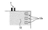
また、図11に示すように、カバー部12に図10に示す導通端子23eの取付位置に対応した箇所に取付穴12a、即ち請求項中の露出手段を形成することで、ユニットハウジング11にカバー部12を取り付けた後に導通端子23eの装着を可能とする構成とすることもできる。このようにすれば、外部からの目視によって導通端子23eの有無を確認するだけで、通信アドレス設定手段23の導通パターンを把握することができるため、製造性及びメンテナンス性の向上を図ることができる。 Further, as shown in FIG. 11, the
このように上述した実施例1,2は本発明の代表的な形態を示したに過ぎず、本発明は、実施形態に限定されるものではない。即ち、本発明の骨子を逸脱しない範囲で種々変形して実施することができる。 As described above, the first and second embodiments described above merely show typical forms of the present invention, and the present invention is not limited to the embodiments. That is, various modifications can be made without departing from the scope of the present invention.
1 中継コネクタユニット
5 第2ワイヤハーネス
7 第1ワイヤハーネス
10 ハウジング
11 ユニットハウジング
12 カバー部
12a 取付穴(露出手段)
16 開口(露出手段)
20 通信中継装置
21 第1接続手段
22 第2接続手段
23 通信アドレス設定手段
23a 接続部
23b 連結部
23d 接地部
23e 導通端子
30 電子制御装置
40 電子機器DESCRIPTION OF
16 Opening (exposure means)
DESCRIPTION OF
Claims (3)
Translated fromJapanese前記通信アドレス設定手段が、前記複数の接続部の導通の有無を外部から目視でき且つ前記導通パターンを設定又は変更できるように形成されていることを特徴とする通信中継装置。First connection means to which the first wire harness connected to the electronic control device is connected, second connection means to which the second wire harness connected to the plurality of electronic devices is connected, and conduction at the plurality of connection portions A communication address setting means for setting a communication address with the electronic control device in a conduction pattern based on presence / absence; electrically connected to the first connection means and the second connection means; and set by the communication address setting means In a communication relay device having communication relay means for relaying communication between the electronic control device and the plurality of electronic devices based on a communication address,
The communication relay device, wherein the communication address setting means is formed so that the presence or absence of conduction of the plurality of connection portions can be visually observed from outside and the conduction pattern can be set or changed.
前記ハウジングが、前記通信中継装置の通信アドレス設定手段を外部から目視可能なように露出させる露出手段を有することを特徴とする中継コネクタユニット。A relay connector unit comprising: the communication relay device according to claim 1; and a housing that accommodates the communication relay device so that electrical connection between the first wire harness and the second wire harness is possible. In
The relay connector unit, wherein the housing has exposure means for exposing the communication address setting means of the communication relay device so as to be visible from the outside.
Priority Applications (4)
| Application Number | Priority Date | Filing Date | Title |
|---|---|---|---|
| JP2007136935AJP2008293747A (en) | 2007-05-23 | 2007-05-23 | Communication relay device and relay connector unit |
| EP08102468AEP1995823B1 (en) | 2007-05-23 | 2008-03-10 | Communication releay apparatus and relay connector unit |
| US12/047,347US7648388B2 (en) | 2007-05-23 | 2008-03-13 | Communication relay apparatus and relay connector unit |
| CN2008100897327ACN101312277B (en) | 2007-05-23 | 2008-04-03 | Communication Relay Equipment and Relay Connector Units |
Applications Claiming Priority (1)
| Application Number | Priority Date | Filing Date | Title |
|---|---|---|---|
| JP2007136935AJP2008293747A (en) | 2007-05-23 | 2007-05-23 | Communication relay device and relay connector unit |
Publications (1)
| Publication Number | Publication Date |
|---|---|
| JP2008293747Atrue JP2008293747A (en) | 2008-12-04 |
Family
ID=39684341
Family Applications (1)
| Application Number | Title | Priority Date | Filing Date |
|---|---|---|---|
| JP2007136935AAbandonedJP2008293747A (en) | 2007-05-23 | 2007-05-23 | Communication relay device and relay connector unit |
Country Status (4)
| Country | Link |
|---|---|
| US (1) | US7648388B2 (en) |
| EP (1) | EP1995823B1 (en) |
| JP (1) | JP2008293747A (en) |
| CN (1) | CN101312277B (en) |
Cited By (7)
| Publication number | Priority date | Publication date | Assignee | Title |
|---|---|---|---|---|
| JP2010192382A (en)* | 2009-02-20 | 2010-09-02 | Yazaki Corp | Communication relay connector |
| JP2010218990A (en)* | 2009-03-19 | 2010-09-30 | Yazaki Corp | Communication relay device, and communication relay connector |
| WO2010116906A1 (en)* | 2009-04-09 | 2010-10-14 | 矢崎総業株式会社 | Communication address detection apparatus, connector with built-in control circuit, and communication address detection method |
| WO2010134463A1 (en)* | 2009-05-20 | 2010-11-25 | 株式会社ステップテクニカ | Address setting device and address setting method |
| KR20110014721A (en)* | 2009-08-05 | 2011-02-14 | 한국단자공업 주식회사 | Connector assembly for can communication device |
| JP2011076972A (en)* | 2009-10-01 | 2011-04-14 | Yazaki Corp | Harness connection structure using connector with built-in function |
| JP2013037975A (en)* | 2011-08-10 | 2013-02-21 | Yazaki Corp | Connector incorporating communication function |
Families Citing this family (13)
| Publication number | Priority date | Publication date | Assignee | Title |
|---|---|---|---|---|
| JP2011093374A (en)* | 2009-10-28 | 2011-05-12 | Yazaki Corp | Wire harness, and electronic equipment control system |
| DE102010033545A1 (en)* | 2010-08-05 | 2012-02-09 | Valeo Schalter Und Sensoren Gmbh | Contacting devices i.e. displacement terminal-plug connectors, for contacting e.g. flat strip cable in bus system for motor car, has displacement terminal needed for address coding and clamped at electric conductors |
| US9810732B2 (en) | 2010-11-24 | 2017-11-07 | Ziota Technology Inc. | Universal mate-in cable interface system |
| US10088501B2 (en) | 2010-11-24 | 2018-10-02 | Ziota Technology Inc. | Universal mate-in cable interface system |
| US8547108B2 (en)* | 2010-11-24 | 2013-10-01 | Ziota Technology Inc. | Universal mate-in cable interface system |
| US8939789B2 (en)* | 2011-01-05 | 2015-01-27 | Lennox Industries Inc. | Device employable in different circuit configurations using parallel wiring harnesses, a HVAC system employing the device and a method of manufacturing a HVAC system |
| JP5875098B2 (en)* | 2011-06-30 | 2016-03-02 | 矢崎総業株式会社 | Wire harness structure and electronic device control system |
| JP2013071611A (en) | 2011-09-28 | 2013-04-22 | Nissan Motor Co Ltd | Vehicle data setting system and output setting method thereof |
| JP2014013682A (en)* | 2012-07-04 | 2014-01-23 | Yazaki Corp | Housing for connector |
| US9343861B2 (en)* | 2013-01-25 | 2016-05-17 | Tyco Electronics Corporation | Communication module adaptor |
| JP2016015821A (en)* | 2014-07-02 | 2016-01-28 | 株式会社オートネットワーク技術研究所 | Electric connection box |
| PL3197671T3 (en)* | 2014-09-23 | 2022-02-21 | Korsch Ag | Tablet machine and method for identifying a pressure roller column in a tabletting machine |
| US9780459B1 (en)* | 2016-03-30 | 2017-10-03 | Te Connectivity Corporation | Linking cable connector |
Citations (4)
| Publication number | Priority date | Publication date | Assignee | Title |
|---|---|---|---|---|
| JP2000286027A (en)* | 1999-03-29 | 2000-10-13 | Yazaki Corp | Joint connector and connector for branch connection |
| JP2005276489A (en)* | 2004-03-23 | 2005-10-06 | Auto Network Gijutsu Kenkyusho:Kk | Connector device with control function |
| JP2005286471A (en)* | 2004-03-29 | 2005-10-13 | Auto Network Gijutsu Kenkyusho:Kk | Connector device with control function |
| JP2005285460A (en)* | 2004-03-29 | 2005-10-13 | Auto Network Gijutsu Kenkyusho:Kk | Connector device with control function |
Family Cites Families (8)
| Publication number | Priority date | Publication date | Assignee | Title |
|---|---|---|---|---|
| US5181859A (en) | 1991-04-29 | 1993-01-26 | Trw Inc. | Electrical connector circuit wafer |
| FR2763718B1 (en) | 1997-05-20 | 1999-07-16 | Scm Schneider Microsysteme Mic | CONNECTOR WITH DIRECT OR INDIRECT INSERTION OF A CHIP CARD WITHIN IT |
| DE19851739C2 (en) | 1998-11-10 | 2003-07-31 | Fahrzeugklimaregelung Gmbh | Device for addressing a bus subscriber |
| JP4303342B2 (en)* | 1999-01-11 | 2009-07-29 | 本田技研工業株式会社 | Multi-cylinder engine for motorcycles |
| US6447331B1 (en)* | 1999-05-19 | 2002-09-10 | Sumitomo Wiring Systems, Ltd. | Joint connector and method of producing joint connector |
| US6837725B1 (en)* | 2004-01-16 | 2005-01-04 | Deere & Company | Connector assembly |
| JP2005285411A (en) | 2004-03-29 | 2005-10-13 | Auto Network Gijutsu Kenkyusho:Kk | Connector device with control function and address setting method thereof |
| JP4346592B2 (en)* | 2005-03-09 | 2009-10-21 | 古河電気工業株式会社 | Communication control IC built-in connector and wiring body with communication control IC built-in connector |
- 2007
- 2007-05-23JPJP2007136935Apatent/JP2008293747A/ennot_activeAbandoned
- 2008
- 2008-03-10EPEP08102468Apatent/EP1995823B1/ennot_activeNot-in-force
- 2008-03-13USUS12/047,347patent/US7648388B2/ennot_activeExpired - Fee Related
- 2008-04-03CNCN2008100897327Apatent/CN101312277B/ennot_activeExpired - Fee Related
Patent Citations (4)
| Publication number | Priority date | Publication date | Assignee | Title |
|---|---|---|---|---|
| JP2000286027A (en)* | 1999-03-29 | 2000-10-13 | Yazaki Corp | Joint connector and connector for branch connection |
| JP2005276489A (en)* | 2004-03-23 | 2005-10-06 | Auto Network Gijutsu Kenkyusho:Kk | Connector device with control function |
| JP2005286471A (en)* | 2004-03-29 | 2005-10-13 | Auto Network Gijutsu Kenkyusho:Kk | Connector device with control function |
| JP2005285460A (en)* | 2004-03-29 | 2005-10-13 | Auto Network Gijutsu Kenkyusho:Kk | Connector device with control function |
Cited By (10)
| Publication number | Priority date | Publication date | Assignee | Title |
|---|---|---|---|---|
| JP2010192382A (en)* | 2009-02-20 | 2010-09-02 | Yazaki Corp | Communication relay connector |
| JP2010218990A (en)* | 2009-03-19 | 2010-09-30 | Yazaki Corp | Communication relay device, and communication relay connector |
| WO2010116906A1 (en)* | 2009-04-09 | 2010-10-14 | 矢崎総業株式会社 | Communication address detection apparatus, connector with built-in control circuit, and communication address detection method |
| JP2010245988A (en)* | 2009-04-09 | 2010-10-28 | Yazaki Corp | Communication address detecting device, control circuit built-in connector, and communication address detecting method |
| US9160557B2 (en) | 2009-04-09 | 2015-10-13 | Yazaki Corporation | Communication address detection apparatus, connector with built-in control circuit, and communication address detection method |
| WO2010134463A1 (en)* | 2009-05-20 | 2010-11-25 | 株式会社ステップテクニカ | Address setting device and address setting method |
| KR20110014721A (en)* | 2009-08-05 | 2011-02-14 | 한국단자공업 주식회사 | Connector assembly for can communication device |
| KR101640097B1 (en) | 2009-08-05 | 2016-07-18 | 한국단자공업 주식회사 | Connector Assembly for CAN Communication Devices |
| JP2011076972A (en)* | 2009-10-01 | 2011-04-14 | Yazaki Corp | Harness connection structure using connector with built-in function |
| JP2013037975A (en)* | 2011-08-10 | 2013-02-21 | Yazaki Corp | Connector incorporating communication function |
Also Published As
| Publication number | Publication date |
|---|---|
| EP1995823A2 (en) | 2008-11-26 |
| EP1995823B1 (en) | 2012-05-02 |
| US20080293266A1 (en) | 2008-11-27 |
| EP1995823A3 (en) | 2009-07-15 |
| CN101312277B (en) | 2010-09-08 |
| CN101312277A (en) | 2008-11-26 |
| US7648388B2 (en) | 2010-01-19 |
Similar Documents
| Publication | Publication Date | Title |
|---|---|---|
| JP2008293747A (en) | Communication relay device and relay connector unit | |
| US9457741B2 (en) | Wire harness | |
| JP5286105B2 (en) | Communication relay connector | |
| US9825394B2 (en) | Wire harness and manufacturing method of the wire harness | |
| JP2015227089A (en) | Vehicle harness structure | |
| JP2017152102A (en) | Wire harness structure | |
| KR20190039378A (en) | Vehicle electrical center and method of manufacturing same | |
| JP6349162B2 (en) | Manufacturing method of wire harness | |
| WO2020122106A1 (en) | Joint connector | |
| JP2009284622A (en) | Power supply distribution structure of electrical junction box | |
| KR20150008813A (en) | Electrical center for a vehicle | |
| KR102817541B1 (en) | Joint connector | |
| JP3473526B2 (en) | Electrical junction box with vertical busbar | |
| JP5986710B2 (en) | Continuity inspection device and wire harness structure | |
| JP5227864B2 (en) | Communication relay device and communication relay connector | |
| JP2020047367A (en) | Multiplex communication connector | |
| JP2007317990A (en) | Flexible printed wiring board | |
| JP6251709B2 (en) | Wire harness system and wire harness | |
| CN103493312A (en) | Pressure welding device and pressure welding system | |
| US20140287629A1 (en) | Plug-type element | |
| JPH11185885A (en) | Joint connector with overcurrent protection | |
| JP2020155382A (en) | Connector housing and connector | |
| US6746271B2 (en) | Electrical plug connection having an adjustable coding | |
| JP3702758B2 (en) | Electrical junction box | |
| JP2013037975A (en) | Connector incorporating communication function |
Legal Events
| Date | Code | Title | Description |
|---|---|---|---|
| A621 | Written request for application examination | Free format text:JAPANESE INTERMEDIATE CODE: A621 Effective date:20100325 | |
| A977 | Report on retrieval | Free format text:JAPANESE INTERMEDIATE CODE: A971007 Effective date:20111026 | |
| A131 | Notification of reasons for refusal | Free format text:JAPANESE INTERMEDIATE CODE: A131 Effective date:20111101 | |
| A521 | Written amendment | Free format text:JAPANESE INTERMEDIATE CODE: A523 Effective date:20111227 | |
| A131 | Notification of reasons for refusal | Free format text:JAPANESE INTERMEDIATE CODE: A131 Effective date:20120214 | |
| A762 | Written abandonment of application | Free format text:JAPANESE INTERMEDIATE CODE: A762 Effective date:20120409 |