JP2008293665A - Equipment with optical display device - Google Patents
Equipment with optical display deviceDownload PDFInfo
- Publication number
- JP2008293665A JP2008293665AJP2007135061AJP2007135061AJP2008293665AJP 2008293665 AJP2008293665 AJP 2008293665AJP 2007135061 AJP2007135061 AJP 2007135061AJP 2007135061 AJP2007135061 AJP 2007135061AJP 2008293665 AJP2008293665 AJP 2008293665A
- Authority
- JP
- Japan
- Prior art keywords
- light
- light guide
- display
- relay
- incident surface
- Prior art date
- Legal status (The legal status is an assumption and is not a legal conclusion. Google has not performed a legal analysis and makes no representation as to the accuracy of the status listed.)
- Granted
Links
- 230000003287optical effectEffects0.000titleclaimsabstractdescription8
- 238000000149argon plasma sinteringMethods0.000claimsabstractdescription9
- 230000000149penetrating effectEffects0.000claims1
- 239000004925Acrylic resinSubstances0.000description2
- 229920000178Acrylic resinPolymers0.000description2
- 230000008878couplingEffects0.000description2
- 238000010168coupling processMethods0.000description2
- 238000005859coupling reactionMethods0.000description2
- 230000037431insertionEffects0.000description2
- 238000003780insertionMethods0.000description2
- 239000003086colorantSubstances0.000description1
- 238000005034decorationMethods0.000description1
- 230000000694effectsEffects0.000description1
- 238000010438heat treatmentMethods0.000description1
- 229920005668polycarbonate resinPolymers0.000description1
- 239000004431polycarbonate resinSubstances0.000description1
- 239000000758substrateSubstances0.000description1
Images


Landscapes
- Planar Illumination Modules (AREA)
Abstract
Description
Translated fromJapanese本発明は、光表示装置を備えた機器に関するもので、温風暖房機や空気清浄機等の種々の機器に使用できる。 The present invention relates to a device provided with a light display device, and can be used for various devices such as a warm air heater and an air purifier.
従来、温風暖房機や空気清浄機等の機器においては、使用者に運転状態を視認させる目的や、装飾の目的で、本体ケースの前面に設けた透明な表示用導光体(12)を背後から照明することにより発光させるものがある。 Conventionally, in devices such as hot air heaters and air purifiers, a transparent display light guide (12) provided on the front surface of the main body case has been provided for the purpose of making the user visually aware of the operating state or for the purpose of decoration. Some emit light by illuminating from behind.
図5は、従来例を説明するための、光表示装置を備えた温風暖房機の一部切欠の斜視図である。
本体ケース(1)の前面パネル(11)に開設された上下に長い差込スリット(13)には、透明ポリカーボネート樹脂から成る棒状の表示用導光体(12)が嵌入されており、該表示用導光体(12)は、バックライト用の縦長長方形の反射板(14)で背後から照明されるようになっている。FIG. 5 is a partially cutaway perspective view of a warm air heater provided with a light display device for explaining a conventional example.
A bar-shaped light guide for display (12) made of transparent polycarbonate resin is inserted into the vertically long insertion slit (13) opened in the front panel (11) of the main body case (1), and the display The light guide (12) is illuminated from behind by a vertically-long rectangular reflector (14) for backlight.
反射板(14)は、本体ケース(1)内に設けられたベース板(15)から切起こして形成されており、該反射板(14)に対して横方向から対向する位置には発光ダイオードからなる光源(16)が設けられている。
このものでは、光源(16)からの光線が反射板(14)で反射し、該反射光が表示用導光体(12)を透過して使用者に視認される。
In this device, the light beam from the light source (16) is reflected by the reflecting plate (14), and the reflected light passes through the display light guide (12) and is visually recognized by the user.
しかしながら、上記従来のものでは、表示用導光体(12)の表面全体の輝度を均一にしつつ、高い輝度に設定することができない、という問題があった。
上記問題点について、更に詳述する。
上記従来のものでは、反射板(14)に光源(16)を接近させると、反射板(14)に於いて光源(16)に対向する部分が強く照明されるから、該部分の輝度が局部的に高くなり、これにより、反射板(14)の表面の輝度が場所によってばらつく。このことから、前面パネル(11)から露出する表示用導光体(12)の表面の輝度も場所によってばらつき、前記表面全体の輝度が均一にならない。一方、前記表示用導光体(12)の表面全体の輝度を均一にするためは、反射板(14)の中央部と長手方向端部の夫々から光源(16)までの距離を略一致させる必要があり、そのためには、反射板(14)から光源(16)までの距離を大きくする必要がある。しかし、反射板(14)から光源(16)までの距離を大きくすると、反射板(14)に照射されずに周囲に漏れる光線の割合が増加する。このことから、上記従来のものでは、表示用導光体(12)の表面全体の輝度を均一にしつつ、高い輝度に設定することができないのである。However, the conventional device has a problem that the luminance of the entire surface of the light guide for display (12) cannot be set to a high luminance while being uniform.
The above problem will be further described in detail.
In the above conventional one, when the light source (16) is brought close to the reflecting plate (14), the portion facing the light source (16) in the reflecting plate (14) is strongly illuminated. As a result, the brightness of the surface of the reflector (14) varies from place to place. For this reason, the luminance of the surface of the display light guide (12) exposed from the front panel (11) also varies depending on the location, and the luminance of the entire surface is not uniform. On the other hand, in order to make the luminance of the entire surface of the display light guide (12) uniform, the distances from the central portion and the longitudinal end portion of the reflector (14) to the light source (16) are substantially matched. For this purpose, it is necessary to increase the distance from the reflector (14) to the light source (16). However, when the distance from the reflecting plate (14) to the light source (16) is increased, the proportion of light rays that leak to the surroundings without being irradiated on the reflecting plate (14) increases. For this reason, in the above-described conventional device, it is impossible to set the luminance to a high level while making the luminance of the entire surface of the display light guide (12) uniform.
本発明はかかる点に鑑みて成されたもので、
本体ケース(1)の前面パネル(11)に設けられた表示用導光体(12)の表面全体の輝度を均一にしつつ、高い輝度に設定できるようにすることを課題とする。The present invention has been made in view of such points,
It is an object to make it possible to set a high luminance while making the luminance of the entire surface of the display light guide (12) provided on the front panel (11) of the main body case (1) uniform.
[請求項1に係る発明]
上記課題を解決する為の請求項1に係る発明の解決手段は、
『本体ケース(1)の前面パネル(11)を表裏に貫通する表示用導光体(12)と、
前記表示用導光体(12)の配設部に対して上下方向又は左右方向にずれた部位の本体ケース(1)内に配設された光源(16)と、
前記光源(16)から放射される光線を前記表示用導光体(12)の光入射面(122)のみに導く為の中継用導光体(18)とを具備し、
前記中継用導光体(18)の光入射面(180)は前記光源(16)に対向していると共に、前記中継用導光体(18)の光射出面(181)は前記表示用導光体(12)の光入射面(122)に対向しており、
前記表示用導光体(12)の光入射面(122)もしくは光射出面(123)、又は、前記中継用導光体(18)の光射出面(181)の、何れかひとつの面、又は2以上の面は、光散乱面になっている』ことである。
上記解決手段によれば、中継用導光体(18)の光入射面(180)は光源(16)に対向していると共に、中継用導光体(18)の光射出面(181)は表示用導光体(12)の光入射面(122)に対向している。[Invention of Claim 1]
The solution means of the invention according to
`` Display light guide (12) that penetrates the front panel (11) of the main body case (1) from the front and back,
A light source (16) disposed in the main body case (1) at a position shifted in the vertical direction or the horizontal direction with respect to the arrangement portion of the display light guide (12);
A relay light guide (18) for guiding light emitted from the light source (16) only to the light incident surface (122) of the display light guide (12);
The light incident surface (180) of the relay light guide (18) faces the light source (16), and the light emission surface (181) of the relay light guide (18) is the display light guide. It faces the light incident surface (122) of the light body (12),
Any one of the light incident surface (122) or the light exit surface (123) of the display light guide (12), or the light exit surface (181) of the relay light guide (18), Or two or more surfaces are light scattering surfaces.
According to the above solution, the light incident surface (180) of the relay light guide (18) faces the light source (16), and the light exit surface (181) of the relay light guide (18) It faces the light incident surface (122) of the display light guide (12).
従って、光源(16)から放射される光線は、光源(16)に対向する中継用導光体(18)の光入射面(180)に入射して反対側の光射出面側(181)に導かれる。そして、該光射出面(181)から射出された光線は、これに対向する表示用導光体(12)の光入射面(122)に入射し、この入射光が表示用導光体(12)を透過して使用者に視認される。そして、光源(16)から放射された光線は、前記経路で伝達される間に中継用導光体(18)や表示用導光体(12)の内部で次第に拡散し、これにより、表示用導光体(12)の光射出面(123)の全体に光が広がって輝度が均一化される。 Therefore, the light emitted from the light source (16) enters the light incident surface (180) of the relay light guide (18) facing the light source (16) and enters the opposite light exit surface side (181). Led. The light emitted from the light exit surface (181) is incident on the light incident surface (122) of the display light guide (12) facing the light exit surface (181), and the incident light is displayed on the display light guide (12). ) And is visible to the user. Then, the light emitted from the light source (16) gradually diffuses inside the relay light guide (18) and the display light guide (12) while being transmitted through the path, thereby displaying the light. Light spreads over the entire light exit surface (123) of the light guide (12) to make the luminance uniform.
又、上記解決手段によれば、前記表示用導光体(12)の光入射面(122)もしくは光射出面(123)、又は、前記中継用導光体(18)の光射出面(181)の、何れかひとつの面、又は2以上の面は、光散乱面になっている。従って、前記光散乱面による光線の散乱で表示用導光体(12)の光射出面(123)全体に光が拡散し、該光射出面(123)全体の輝度が一層均一化される。よって、表示用導光体(12)の光射出面(123)を高輝度に設定すべく、光源(16)を中継用導光体(18)の光入射面に接近させて光線が周囲に漏れないようにしても、表示用導光体(12)の光射出面(123)全体の輝度が均一になり易い。 According to the above solution, the light incident surface (122) or the light exit surface (123) of the display light guide (12) or the light exit surface (181) of the relay light guide (18). Any one surface or two or more surfaces of () is a light scattering surface. Accordingly, the light is scattered by the light scattering surface to diffuse the entire light exit surface (123) of the display light guide (12), and the brightness of the entire light exit surface (123) is made more uniform. Therefore, in order to set the light exit surface (123) of the display light guide (12) to a high brightness, the light source (16) is brought close to the light incident surface of the relay light guide (18), so that the light beam is surrounded. Even if it does not leak, the luminance of the entire light exit surface (123) of the display light guide (12) tends to be uniform.
[請求項2に係る発明]
請求項1に係る発明に於いて、
『前記中継用導光体(18)は、
一端面が前記光入射面(180)である板状部を備えており、
前記板状部は、前記光入射面(180)の両端に続く一対の側面(a)(a)が前記光入射面(180)から離反するに従って次第に広がるように傾斜している』ものとすることができる。
このものでは、前記板状部の光源(16)側の一端面である光入射面(180)の両端位置から同方向へ屈曲する側面(a)(a)が、前記光入射面(180)から離反するに従って次第に広がるように傾斜している。そして、前記側面(a)(a)は、中継用導光体(18)の内部を進む光線を反射させる為の反射面として機能する。従って、前記側面(a)(a)が光入射面(180)の両端から直角に延びる場合(側面(a)(a)が平行な場合)に比べ、前記光線を中継用導光体(18)の光射出面(181)側に集め易くなる。[Invention of Claim 2]
In the invention according to
`` The light guide for relay (18)
One end surface is provided with a plate-like portion that is the light incident surface (180),
The plate-like portion is inclined such that a pair of side surfaces (a) and (a) continuing from both ends of the light incident surface (180) gradually spread as the distance from the light incident surface (180) increases. be able to.
In this structure, the side surfaces (a) and (a) bent in the same direction from the both end positions of the light incident surface (180) which is one end surface of the light source (16) side of the plate-shaped portion are the light incident surface (180). It is inclined to spread gradually as it gets away from. The side surfaces (a) and (a) function as a reflecting surface for reflecting the light beam traveling inside the relay light guide (18). Therefore, compared with the case where the side surfaces (a) and (a) extend at right angles from both ends of the light incident surface (180) (when the side surfaces (a) and (a) are parallel), the light beam for relaying (18 ) On the light exit surface (181) side.
[請求項3に係る発明]
請求項2に係る発明に於いて、
『前記表示用導光体(12)は、前記前面パネル(11)の左右方向に長い棒状に形成されており、
前記板状部は、前記光源(16)に対向する光入射面(180)から上方に延びる鉛直板(18a)であり、
前記中継用導光体(18)は、前記鉛直板(18a)の上端から前記表示用導光体(12)の光入射面(121)側に向けて屈曲する水平板(18b)を備えている』ものとすることができる。
このものでは、中継用導光体(18)は、鉛直板(18a)とその上端から屈曲する水平板(18b)とから成るL型断面を有している。
従って、鉛直板(18a)の上下寸法を長く設定することにより、中継用導光体(18)の光入射面(180)から光射出面(181)に至る光路を長くすることができる。[Invention of Claim 3]
In the invention according to
`` The display light guide (12) is formed in a bar shape long in the left-right direction of the front panel (11),
The plate-like portion is a vertical plate (18a) extending upward from a light incident surface (180) facing the light source (16),
The relay light guide (18) includes a horizontal plate (18b) bent from the upper end of the vertical plate (18a) toward the light incident surface (121) of the display light guide (12). It can be.
In this structure, the relay light guide (18) has an L-shaped cross section composed of a vertical plate (18a) and a horizontal plate (18b) bent from its upper end.
Therefore, by setting the vertical dimension of the vertical plate (18a) to be long, the optical path from the light incident surface (180) of the relay light guide (18) to the light exit surface (181) can be lengthened.
よって、前記長い光路内を光線が伝達されて行く間に、該光線が中継用導光体(18)の内部全体に拡散し易くなる。従って、中継用導光体(18)の水平板(18b)の前後長さを短く設定しても、中継用導光体(18)の光射出面(181)全体の輝度を均一にすることができ、その結果、表示用導光体(12)の光射出面(123)全体の輝度を均一にすることができる。 Therefore, while a light beam is transmitted through the long optical path, the light beam is easily diffused throughout the interior of the relay light guide (18). Therefore, even if the front and rear lengths of the horizontal plate (18b) of the relay light guide (18) are set short, the luminance of the entire light exit surface (181) of the relay light guide (18) is made uniform. As a result, the luminance of the entire light exit surface (123) of the display light guide (12) can be made uniform.
本発明は次の特有の効果を有する。
請求項1に係る発明によれば、前述のように、表示用導光体(12)の光射出面(123)を高輝度に設定すべく、光源(16)を中継用導光体(18)の光入射面(180)に接近させて光線が周囲に漏れないようにしても、表示用導光体(12)の表面である光射出面(123)全体の輝度が均一になり易い。従って、表示用導光体(12)の表面全体の輝度を均一にしつつ、高い輝度に設定できる。The present invention has the following specific effects.
According to the first aspect of the present invention, as described above, the light source (16) is connected to the relay light guide (18) in order to set the light exit surface (123) of the display light guide (12) to high luminance. ), The entire light emission surface (123), which is the surface of the display light guide (12), is likely to be uniform in brightness. Accordingly, the luminance of the entire surface of the display light guide (12) can be set high while maintaining the same luminance.
請求項2に係る発明では、上記のように、前記側面(a)(a)が光入射面(180)の両端から直角に延びる場合(側面(a)(a)が平行な場合)に比べ、前記光線を中継用導光体(18)の光射出面(181)側に集め易くなる。従って、表示用導光体(12)の光射出面(123)の輝度を一層高くすることができる。 In the invention according to
請求項3に係る発明によれば、既述したように、中継用導光体(18)の水平板(18b)の前後長さを短く設定しても、表示用導光体(12)の光射出面(123)全体の輝度を均一にすることができる。よって、中継用導光体(18)等を配設するために本体ケース(1)内に形成された部品配置空間が前後に狭い場合であっても、表示用導光体(12)の光射出面(123)全体の輝度を均一にすることができる。 According to the invention of
以下に、本発明を実施するための最良の形態について添付図面を参照しながら説明する。
図1〜3は、本願発明を温風暖房機に適用した場合を例示した図である。
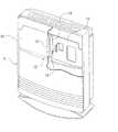
図1に示すように、本発明の実施の形態に係る温風暖房機の本体ケース(1)は、脚部(20)上に固定される箱状主体(10)と、箱状主体(10)の前方開放部を覆う前面パネル(11)とを具備している。The best mode for carrying out the present invention will be described below with reference to the accompanying drawings.
FIGS. 1-3 is the figure which illustrated the case where this invention is applied to a warm air heater.
As shown in FIG. 1, a main body case (1) of a hot air heater according to an embodiment of the present invention includes a box-shaped main body (10) fixed on a leg (20) and a box-shaped main body (10 ) And a front panel (11) covering the front opening portion.
箱状主体(10)の上面中央に重ねられた操作プレート(22)には、操作スイッチ(23)(23)や、運転状態等を表示する表示部(24)が設けられている。又、箱状主体(10)には、操作プレート(22)の左右から箱状主体(10)の両側部を経て底面に至る領域に沿って縁巻き状に配設される装飾枠(25)(25)が外嵌されている。 The operation plate (22) superimposed on the center of the upper surface of the box-shaped main body (10) is provided with operation switches (23) and (23) and a display unit (24) for displaying the operation state. Further, the box-shaped main body (10) includes a decorative frame (25) arranged in an edge-wrapped manner along the region from the left and right of the operation plate (22) to the bottom surface through both sides of the box-shaped main body (10). (25) is externally fitted.
箱状主体(10)の前方開放部を覆う前面パネル(11)は、後方に開放する矩形の浅皿状に形成されており、下部には、ルーバ(260)を備えた温風吹出し口(26)が開設されている。
図1、2に示すように、前面パネル(11)の後方開放部の内周に形成された結合フランジ(110)は、箱状主体(10)の前方開放部の内周に設けられた結合フランジ(101)に重ねられた状態で適宜結合されている。The front panel (11) that covers the front opening of the box-shaped main body (10) is formed in a rectangular shallow dish that opens to the rear, and at the bottom, a hot air outlet (with a louver (260)) ( 26) has been established.
As shown in FIGS. 1 and 2, the coupling flange (110) formed on the inner periphery of the rear opening portion of the front panel (11) is a coupling provided on the inner periphery of the front opening portion of the box-shaped main body (10). They are appropriately combined in a state of being overlapped with the flange (101).
前面パネル(11)の中央上端には、化粧板(27)が添設固定されていると共に、該化粧板(27)に開設された横長スリット(28)には、左右方向に長い棒状の表示用導光体(12)の先端頭部(120)が嵌入されている。 A decorative plate (27) is attached and fixed to the center upper end of the front panel (11), and the horizontally long slit (28) established in the decorative plate (27) has a bar-like display that is long in the left-right direction. The tip head (120) of the light guide (12) is inserted.
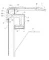
図2に示すように、表示用導光体(12)の先端頭部(120)から後方に突出する突出体(121)は、前面パネル(11)に開設された差込スリット(111)に挿入されており、これにより、表示用導光体(12)が前面パネル(11)を表裏に貫通した構成になっている。又、表示用導光体(12)は、透明なアクリル樹脂で形成されていると共に、その光射出面(123)と光入射面(122)は、微小な凹凸が形成された梨地状の光散乱面になっている。 As shown in FIG. 2, the protrusion (121) protruding backward from the tip head (120) of the display light guide (12) is inserted into the insertion slit (111) provided in the front panel (11). Thus, the display light guide (12) penetrates the front panel (11) on the front and back sides. The display light guide (12) is made of transparent acrylic resin, and its light exit surface (123) and light incident surface (122) have a satin-like light with minute irregularities formed thereon. It is a scattering surface.
箱状主体(10)の内部には、発光ダイオードから成る発光色の異なる四個の光源(16)が基板(17)上に配設されていると共に、光源(16)から放射される光線を表示用導光体(12)の光入射面(122)に導く中継用導光体(18)が設けられている。 Inside the box-shaped main body (10), four light sources (16) having different emission colors composed of light-emitting diodes are arranged on the substrate (17), and rays emitted from the light source (16) are emitted. A relay light guide (18) that leads to the light incident surface (122) of the display light guide (12) is provided.
中継用導光体(18)は透明なアクリル樹脂で形成されていると共に、光源(16)に対向する光入射面(180)から上方に延びる板状部たる鉛直板(18a)とこれの上端から表示用導光体(12)側に屈曲する水平板(18b)から構成されている。鉛直板(18a)は、光入射面(180)の長手方向の両端位置から延びる一対の側面(a)(a)が光入射面(180)から離反するに従って次第に広がるように傾斜した台形に形成されている。従って、図4に示すように、光源(16)から光入射面(180)へ入射した光線(S1)と側面(a)の法線(n1)との入射角(θ1)は、前記側面(a)に代えて鉛直面(b)が形成されている場合の入射角(θ2)(鉛直面(b)の法線(n1)と光線(S1)の成す角)より大きくなる。従って、側面(a)での反射光線(S2)は前記鉛直面(b)での反射光線(S3)に比べ水平板(18b)に近付く方向に設定されるから、光線を中継用導光体(18)の光射出面(181)側に集め易くなる。よって、表示用導光体(12)の光射出面(123)の輝度を一層高くすることができる。 The relay light guide (18) is made of a transparent acrylic resin, and has a vertical plate (18a) as a plate-like portion extending upward from the light incident surface (180) facing the light source (16) and the upper end of the plate. And a horizontal plate (18b) bent toward the display light guide (12) side. The vertical plate (18a) is formed into a trapezoid that is inclined so that the pair of side surfaces (a) and (a) extending from both longitudinal positions of the light incident surface (180) gradually spreads as they move away from the light incident surface (180). Has been. Therefore, as shown in FIG. 4, the incident angle (θ1) between the light beam (S1) incident on the light incident surface (180) from the light source (16) and the normal line (n1) of the side surface (a) is Instead of a), the incident angle (θ2) when the vertical surface (b) is formed (the angle formed by the normal (n1) of the vertical surface (b) and the light beam (S1)) is larger. Therefore, the reflected light beam (S2) on the side surface (a) is set in a direction closer to the horizontal plate (18b) than the reflected light beam (S3) on the vertical surface (b). It becomes easy to collect on the light exit surface (181) side of (18). Therefore, the luminance of the light exit surface (123) of the display light guide (12) can be further increased.
上記中継用導光体(18)は、光源(16)に対向する光入射面(180)と表示用導光体(12)の光入射面(122)に対向する光射出面(181)が、共に、微小な凹凸が形成された梨地状の光散乱面になっている。 The relay light guide (18) has a light incident surface (180) facing the light source (16) and a light exit surface (181) facing the light incident surface (122) of the display light guide (12). Both have a satin-like light scattering surface on which minute irregularities are formed.
又、中継用導光体(18)は、前述の光源(16)と共に収納ケース(3)に収納されていると共に、図3に示すように、中継用導光体(18)の水平板(18b)の左右両端には取付フランジ(183)(183)が突設されている。そして、この取付フランジ(183)(183)は、収納ケース(3)の奥壁(30)に平行な固定壁(31)に形成されたネジ孔(32)に対し、ビス(33)(33)で固定されるようになっている。又、中継用導光体(18)の光射出面(181)は、表示用導光体(12)の光入射面(122)に平行姿勢で接近している(図2参照)。尚、前記表示用導光体(12)、中継用導光体(18)、及び光源(16)等の配設部の下方には、暖房用の温風を生成する器具本体(4)が配設されている。 The relay light guide (18) is stored in the storage case (3) together with the light source (16) described above, and as shown in FIG. 3, the horizontal light guide (18) horizontal plate ( Mounting flanges (183) and (183) project from the left and right ends of 18b). And this mounting flange (183) (183) is screw (33) (33) to the screw hole (32) formed in the fixed wall (31) parallel to the back wall (30) of the storage case (3). ) Is fixed. The light exit surface (181) of the relay light guide (18) is close to the light incident surface (122) of the display light guide (12) in a parallel posture (see FIG. 2). An appliance body (4) for generating warm air for heating is provided below the display light guide (12), the relay light guide (18), and the light source (16). It is arranged.
上記のものでは、中継用導光体(18)の光入射面(180)は光源(16)に対向していると共に、中継用導光体(18)の光射出面(181)は表示用導光体(12)の光入射面(122)に対向している。 In the above, the light incident surface (180) of the relay light guide (18) faces the light source (16), and the light exit surface (181) of the relay light guide (18) is for display. It faces the light incident surface (122) of the light guide (12).
従って、光源(16)から放射される光線は、光源(16)に対向する中継用導光体(18)の光入射面(180)に入射して反対側の光射出面(181)側に導かれる。そして、該光射出面(181)から射出された光線は、これに対向する表示用導光体(12)の光入射面(122)に入射し、この入射光が表示用導光体(12)を透過して使用者に視認される。 Therefore, the light beam emitted from the light source (16) is incident on the light incident surface (180) of the relay light guide (18) facing the light source (16) and enters the opposite light exit surface (181) side. Led. The light emitted from the light exit surface (181) is incident on the light incident surface (122) of the display light guide (12) facing the light exit surface (181), and the incident light is displayed on the display light guide (12). ) And is visible to the user.
この場合、光源(16)から放射された光線は、中継用導光体(18)や表示用導光体(12)内で伝達される間に、これら中継用導光体(18)や表示用導光体(12)の内部で次第に拡散し、これにより、表示用導光体(12)の光射出面(123)の全体に光が広がって輝度が均一化される。 In this case, while the light beam emitted from the light source (16) is transmitted in the relay light guide (18) and the display light guide (12), these relay light guide (18) and display The light gradually diffuses inside the light guide for light (12), whereby light spreads over the entire light exit surface (123) of the light guide for display (12) and the luminance is made uniform.
又、表示用導光体(12)の光入射面(122)及び光射出面(123)と、中継用導光体(18)の光射出面(181)は、梨地状の光散乱面になっている。従って、前記光散乱面による光の散乱で表示用導光体(12)の光射出面(123)全体に光が拡散し、該射出面(123)全体の輝度が一層均一化される。よって、表示用導光体(12)の光射出面(123)を高輝度に設定すべく、光源(16)を中継用導光体(18)の光入射面に接近させて光線が周囲に漏れないようにしても、表示用導光体(12)の光射出面(123)全体の輝度が均一になり易い。 Further, the light incident surface (122) and the light exit surface (123) of the display light guide (12) and the light exit surface (181) of the relay light guide (18) are formed into a satin-like light scattering surface. It has become. Accordingly, the light is diffused by the light scattering surface to diffuse the entire light exit surface (123) of the display light guide (12), and the brightness of the entire exit surface (123) is made more uniform. Therefore, in order to set the light exit surface (123) of the display light guide (12) to a high brightness, the light source (16) is brought close to the light incident surface of the relay light guide (18), so that the light beam is surrounded. Even if it does not leak, the luminance of the entire light exit surface (123) of the display light guide (12) tends to be uniform.
[その他]
1.上記実施の形態では、表示用導光体(12)の光入射面(122)及び光射出面(123)と、前記中継用導光体(18)の光射出面(181)は、梨地状の光散乱面になっているが、前記表示用導光体(12)の光入射面(122)もしくは(123)、又は、前記中継用導光体(18)の光射出面(181)の、何れかひとつの面、又は2つの面を、光散乱面にしてもよい。
2.上記実施の形態では、本願発明を温風暖房機に適用した場合を例示的に説明したが、本願発明は、空気清浄機やその他の機器にも適用できる。
3.表示用導光体(12)を縦長の姿勢で前面パネル(11)に配設してもよい。この場合、表示用導光体(12)の配設部に対して光源(16)(16)を左右方向にずらした位置に配設し、更に、中継用導光体(18)や光源(16)(16)の配設姿勢を鉛直面内で90度回転させる。[Others]
1. In the above embodiment, the light incident surface (122) and the light exit surface (123) of the display light guide (12) and the light exit surface (181) of the relay light guide (18) are satin-like. The light incident surface (122) or (123) of the display light guide (12), or the light exit surface (181) of the relay light guide (18). Any one surface or two surfaces may be light scattering surfaces.
2. In the above embodiment, the case where the present invention is applied to a hot air heater has been described as an example, but the present invention can also be applied to an air purifier and other devices.
3. The display light guide (12) may be disposed on the front panel (11) in a vertically long posture. In this case, the light sources (16) and (16) are arranged at positions shifted in the left-right direction with respect to the arrangement part of the display light guide (12), and further, the relay light guide (18) and the light source ( 16) The arrangement posture of (16) is rotated 90 degrees in the vertical plane.
(1)・・・本体ケース
(11)・・・前面パネル
(12)・・・表示用導光体
(16)・・・光源
(18)・・・中継用導光体
(18a)・・・鉛直板
(18b)・・・水平板
(122)(180)・・・光入射面
(123)(181)・・・光射出面
(a)・・・側面(1) ... Body case
(11) ・ ・ ・ Front panel
(12) ・ ・ ・ Light guide for display
(16) ... Light source
(18) ・ ・ ・ Light guide for relay
(18a) ・ ・ ・ Vertical plate
(18b) ・ ・ ・ Horizontal plate
(122) (180) ・ ・ ・ Light incident surface
(123) (181) ・ ・ ・ Light exit surface
(a) ・ ・ ・ Side
Claims (3)
Translated fromJapanese前記表示用導光体(12)の配設部に対して上下方向又は左右方向にずれた部位の本体ケース(1)内に配設された光源(16)と、
前記光源(16)から放射される光線を前記表示用導光体(12)の光入射面(122)のみに導く為の中継用導光体(18)とを具備し、
前記中継用導光体(18)の光入射面(180)は前記光源(16)に対向していると共に、前記中継用導光体(18)の光射出面(181)は前記表示用導光体(12)の光入射面(122)に対向しており、
前記表示用導光体(12)の光入射面(122)もしくは光射出面(123)、又は、前記中継用導光体(18)の光射出面(181)の、何れかひとつの面、又は2以上の面は、光散乱面になっている、光表示装置付の機器。A light guide for display (12) penetrating the front panel (11) of the main body case (1) on the front and back, and
A light source (16) disposed in the main body case (1) at a position shifted in the vertical direction or the horizontal direction with respect to the arrangement portion of the display light guide (12);
A relay light guide (18) for guiding light emitted from the light source (16) only to the light incident surface (122) of the display light guide (12);
The light incident surface (180) of the relay light guide (18) faces the light source (16), and the light emission surface (181) of the relay light guide (18) is the display light guide. It faces the light incident surface (122) of the light body (12),
Any one of the light incident surface (122) or the light exit surface (123) of the display light guide (12), or the light exit surface (181) of the relay light guide (18), Alternatively, two or more surfaces are light scattering surfaces, and the device with an optical display device.
前記中継用導光体(18)は、
一端面が前記光入射面(180)である板状部を備えており、
前記板状部は、前記光入射面(180)の両端に続く一対の側面(a)(a)が前記光入射面(180)から離反するに従って次第に広がるように傾斜している、光表示装置付の機器。In the apparatus with an optical display device according to claim 1,
The relay light guide (18),
One end surface is provided with a plate-like portion that is the light incident surface (180),
The plate-like portion is inclined such that a pair of side surfaces (a) and (a) continuing from both ends of the light incident surface (180) gradually expands as the distance from the light incident surface (180) increases. Attached equipment.
前記表示用導光体(12)は、前記前面パネル(11)の左右方向に長い棒状に形成されており、
前記板状部は、前記光源(16)に対向する光入射面(180)から上方に延びる鉛直板(18a)であり、
前記中継用導光体(18)は、前記鉛直板(18a)の上端から前記表示用導光体(12)の光入射面(121)側に向けて屈曲する水平板(18b)を備えている、光表示装置付の機器。In the apparatus with an optical display device according to claim 2,
The display light guide (12) is formed in a bar shape long in the left-right direction of the front panel (11),
The plate-like portion is a vertical plate (18a) extending upward from a light incident surface (180) facing the light source (16),
The relay light guide (18) includes a horizontal plate (18b) bent from the upper end of the vertical plate (18a) toward the light incident surface (121) of the display light guide (12). A device with an optical display device.
Priority Applications (1)
| Application Number | Priority Date | Filing Date | Title |
|---|---|---|---|
| JP2007135061AJP4642811B2 (en) | 2007-05-22 | 2007-05-22 | Equipment with optical display |
Applications Claiming Priority (1)
| Application Number | Priority Date | Filing Date | Title |
|---|---|---|---|
| JP2007135061AJP4642811B2 (en) | 2007-05-22 | 2007-05-22 | Equipment with optical display |
Publications (2)
| Publication Number | Publication Date |
|---|---|
| JP2008293665Atrue JP2008293665A (en) | 2008-12-04 |
| JP4642811B2 JP4642811B2 (en) | 2011-03-02 |
Family
ID=40168217
Family Applications (1)
| Application Number | Title | Priority Date | Filing Date |
|---|---|---|---|
| JP2007135061AExpired - Fee RelatedJP4642811B2 (en) | 2007-05-22 | 2007-05-22 | Equipment with optical display |
Country Status (1)
| Country | Link |
|---|---|
| JP (1) | JP4642811B2 (en) |
Cited By (1)
| Publication number | Priority date | Publication date | Assignee | Title |
|---|---|---|---|---|
| JP2015002148A (en)* | 2013-06-18 | 2015-01-05 | 株式会社小糸製作所 | Lighting fixture for vehicle |
Citations (10)
| Publication number | Priority date | Publication date | Assignee | Title |
|---|---|---|---|---|
| JPH0997016A (en)* | 1995-10-02 | 1997-04-08 | Oki Electric Ind Co Ltd | Display device of electronic apparatus |
| JPH10260405A (en)* | 1997-03-18 | 1998-09-29 | Seiko Epson Corp | Lighting device, liquid crystal display device and electronic equipment |
| JPH11325562A (en)* | 1998-05-20 | 1999-11-26 | Toshiba Ave Co Ltd | Air conditioner |
| JP2000106049A (en)* | 1998-09-30 | 2000-04-11 | Harness Syst Tech Res Ltd | Lighting equipment |
| JP2001067919A (en)* | 1999-08-30 | 2001-03-16 | Citizen Electronics Co Ltd | Planar light source unit |
| JP2001094269A (en)* | 1999-09-20 | 2001-04-06 | Matsushita Electric Ind Co Ltd | Electronics |
| JP2002013795A (en)* | 2000-06-30 | 2002-01-18 | Hitachi Ltd | Air conditioner, display panel used therefor, and optical display method |
| JP2002299689A (en)* | 2001-03-30 | 2002-10-11 | Mitsumi Electric Co Ltd | Light emitting indicator |
| JP2006196239A (en)* | 2005-01-12 | 2006-07-27 | Rinnai Corp | Light emitting device |
| JP2006310112A (en)* | 2005-04-28 | 2006-11-09 | Fujikura Ltd | White light source |
- 2007
- 2007-05-22JPJP2007135061Apatent/JP4642811B2/ennot_activeExpired - Fee Related
Patent Citations (10)
| Publication number | Priority date | Publication date | Assignee | Title |
|---|---|---|---|---|
| JPH0997016A (en)* | 1995-10-02 | 1997-04-08 | Oki Electric Ind Co Ltd | Display device of electronic apparatus |
| JPH10260405A (en)* | 1997-03-18 | 1998-09-29 | Seiko Epson Corp | Lighting device, liquid crystal display device and electronic equipment |
| JPH11325562A (en)* | 1998-05-20 | 1999-11-26 | Toshiba Ave Co Ltd | Air conditioner |
| JP2000106049A (en)* | 1998-09-30 | 2000-04-11 | Harness Syst Tech Res Ltd | Lighting equipment |
| JP2001067919A (en)* | 1999-08-30 | 2001-03-16 | Citizen Electronics Co Ltd | Planar light source unit |
| JP2001094269A (en)* | 1999-09-20 | 2001-04-06 | Matsushita Electric Ind Co Ltd | Electronics |
| JP2002013795A (en)* | 2000-06-30 | 2002-01-18 | Hitachi Ltd | Air conditioner, display panel used therefor, and optical display method |
| JP2002299689A (en)* | 2001-03-30 | 2002-10-11 | Mitsumi Electric Co Ltd | Light emitting indicator |
| JP2006196239A (en)* | 2005-01-12 | 2006-07-27 | Rinnai Corp | Light emitting device |
| JP2006310112A (en)* | 2005-04-28 | 2006-11-09 | Fujikura Ltd | White light source |
Cited By (2)
| Publication number | Priority date | Publication date | Assignee | Title |
|---|---|---|---|---|
| JP2015002148A (en)* | 2013-06-18 | 2015-01-05 | 株式会社小糸製作所 | Lighting fixture for vehicle |
| CN105308384A (en)* | 2013-06-18 | 2016-02-03 | 株式会社小糸制作所 | Vehicular lamp |
Also Published As
| Publication number | Publication date |
|---|---|
| JP4642811B2 (en) | 2011-03-02 |
Similar Documents
| Publication | Publication Date | Title |
|---|---|---|
| JP4740367B2 (en) | Shelf structure lighting equipment | |
| JP2008130336A (en) | Surface light source device and guide light equipped with the same | |
| KR101605184B1 (en) | Display device | |
| JP2008103273A (en) | Vehicle lighting | |
| JP2017126586A (en) | Lighting device | |
| JP2015114005A (en) | Refrigerator | |
| JP4642811B2 (en) | Equipment with optical display | |
| JP6306301B2 (en) | Light emitting device for forming a linear light emission pattern | |
| JP6138644B2 (en) | Lighting device | |
| JP2005129409A (en) | Backlight apparatus | |
| US9170004B2 (en) | Device for displaying graphical symbols | |
| JP3721959B2 (en) | Lighting equipment for display | |
| JP2009125180A (en) | Light-emitting device for game device and game device | |
| JP4161972B2 (en) | lighting equipment | |
| JP2009096388A (en) | Vehicular cabin luminaire and its structure | |
| JP6167448B2 (en) | Kitchen equipment | |
| JP5808995B2 (en) | Vehicle lighting | |
| JP2010017249A (en) | Game machine | |
| JP2017185869A (en) | Illumination structure of operation device | |
| CN101004244B (en) | Illumination device | |
| JP2009009825A (en) | Surface light-emitting device, and illuminating signboard equipped with this | |
| JP5162389B2 (en) | Lighting device | |
| JP4545596B2 (en) | Light emitting device | |
| JP5861097B2 (en) | lighting equipment | |
| JP2013218965A (en) | Lighting fixture |
Legal Events
| Date | Code | Title | Description |
|---|---|---|---|
| A621 | Written request for application examination | Free format text:JAPANESE INTERMEDIATE CODE: A621 Effective date:20090324 | |
| A977 | Report on retrieval | Free format text:JAPANESE INTERMEDIATE CODE: A971007 Effective date:20100820 | |
| A131 | Notification of reasons for refusal | Free format text:JAPANESE INTERMEDIATE CODE: A131 Effective date:20100831 | |
| A521 | Request for written amendment filed | Free format text:JAPANESE INTERMEDIATE CODE: A523 Effective date:20101019 | |
| TRDD | Decision of grant or rejection written | ||
| A01 | Written decision to grant a patent or to grant a registration (utility model) | Free format text:JAPANESE INTERMEDIATE CODE: A01 Effective date:20101116 | |
| A01 | Written decision to grant a patent or to grant a registration (utility model) | Free format text:JAPANESE INTERMEDIATE CODE: A01 | |
| A61 | First payment of annual fees (during grant procedure) | Free format text:JAPANESE INTERMEDIATE CODE: A61 Effective date:20101201 | |
| R150 | Certificate of patent or registration of utility model | Ref document number:4642811 Country of ref document:JP Free format text:JAPANESE INTERMEDIATE CODE: R150 Free format text:JAPANESE INTERMEDIATE CODE: R150 | |
| FPAY | Renewal fee payment (event date is renewal date of database) | Free format text:PAYMENT UNTIL: 20131210 Year of fee payment:3 | |
| R250 | Receipt of annual fees | Free format text:JAPANESE INTERMEDIATE CODE: R250 | |
| R250 | Receipt of annual fees | Free format text:JAPANESE INTERMEDIATE CODE: R250 | |
| R250 | Receipt of annual fees | Free format text:JAPANESE INTERMEDIATE CODE: R250 | |
| R250 | Receipt of annual fees | Free format text:JAPANESE INTERMEDIATE CODE: R250 | |
| R250 | Receipt of annual fees | Free format text:JAPANESE INTERMEDIATE CODE: R250 | |
| R250 | Receipt of annual fees | Free format text:JAPANESE INTERMEDIATE CODE: R250 | |
| R250 | Receipt of annual fees | Free format text:JAPANESE INTERMEDIATE CODE: R250 | |
| R250 | Receipt of annual fees | Free format text:JAPANESE INTERMEDIATE CODE: R250 | |
| R250 | Receipt of annual fees | Free format text:JAPANESE INTERMEDIATE CODE: R250 | |
| LAPS | Cancellation because of no payment of annual fees |