JP2008289792A - Game machine - Google Patents
Game machineDownload PDFInfo
- Publication number
- JP2008289792A JP2008289792AJP2007140663AJP2007140663AJP2008289792AJP 2008289792 AJP2008289792 AJP 2008289792AJP 2007140663 AJP2007140663 AJP 2007140663AJP 2007140663 AJP2007140663 AJP 2007140663AJP 2008289792 AJP2008289792 AJP 2008289792A
- Authority
- JP
- Japan
- Prior art keywords
- disk
- symbol
- diameter
- annular region
- region
- Prior art date
- Legal status (The legal status is an assumption and is not a legal conclusion. Google has not performed a legal analysis and makes no representation as to the accuracy of the status listed.)
- Pending
Links
- 238000001514detection methodMethods0.000claimsdescription17
- 238000000034methodMethods0.000description65
- 230000008569processEffects0.000description64
- 239000004973liquid crystal related substanceSubstances0.000description50
- 230000000694effectsEffects0.000description35
- 238000003860storageMethods0.000description26
- 238000010586diagramMethods0.000description24
- 238000013461designMethods0.000description23
- 230000005540biological transmissionEffects0.000description16
- 238000012545processingMethods0.000description15
- 238000005070samplingMethods0.000description15
- 239000000463materialSubstances0.000description12
- 230000007246mechanismEffects0.000description10
- 238000003780insertionMethods0.000description9
- 230000037431insertionEffects0.000description9
- 238000012544monitoring processMethods0.000description9
- 230000002093peripheral effectEffects0.000description9
- 241000167854Bourreria succulentaSpecies0.000description8
- 235000019693cherriesNutrition0.000description8
- 239000011347resinSubstances0.000description8
- 229920005989resinPolymers0.000description8
- 241000219109CitrullusSpecies0.000description7
- 235000012828Citrullus lanatus var citroidesNutrition0.000description7
- NJPPVKZQTLUDBO-UHFFFAOYSA-NnovaluronChemical compoundC1=C(Cl)C(OC(F)(F)C(OC(F)(F)F)F)=CC=C1NC(=O)NC(=O)C1=C(F)C=CC=C1FNJPPVKZQTLUDBO-UHFFFAOYSA-N0.000description6
- 238000003825pressingMethods0.000description6
- 230000004044responseEffects0.000description4
- 238000000605extractionMethods0.000description3
- 230000000737periodic effectEffects0.000description3
- 239000000047productSubstances0.000description3
- PZTQVMXMKVTIRC-UHFFFAOYSA-Lchembl2028348Chemical compound[Ca+2].[O-]S(=O)(=O)C1=CC(C)=CC=C1N=NC1=C(O)C(C([O-])=O)=CC2=CC=CC=C12PZTQVMXMKVTIRC-UHFFFAOYSA-L0.000description2
- 238000004891communicationMethods0.000description2
- 230000029087digestionEffects0.000description2
- 238000006073displacement reactionMethods0.000description2
- 239000012780transparent materialSubstances0.000description2
- 241001465754MetazoaSpecies0.000description1
- 240000007942Prunus pensylvanicaSpecies0.000description1
- 235000013647Prunus pensylvanicaNutrition0.000description1
- 230000008901benefitEffects0.000description1
- 230000008859changeEffects0.000description1
- 238000004519manufacturing processMethods0.000description1
- 230000001151other effectEffects0.000description1
- 239000012466permeateSubstances0.000description1
Images


Landscapes
- Slot Machines And Peripheral Devices (AREA)
Abstract
Translated fromJapaneseDescription
Translated fromJapanese本発明は、円盤を備えた遊技機に関するものである。 The present invention relates to a gaming machine provided with a disk.
従来、遊技用の図柄がそれぞれの周面に配された複数のリールと、これら各リールに対応するように複数設けられ、前記各リールの周面に配された遊技用の図柄のうちの一部の図柄を遊技者が視認可能なように表示する表示窓と、メダルが投入されていることを条件に、遊技者による操作を検出すると、各リールの回転の開始を要求する信号を出力するスタートスイッチと、遊技者による操作を検出すると、リールの種別に応じて当該リールの回転の停止を要求する信号を出力するストップスイッチと、これらスタートスイッチおよびストップスイッチにより出力された信号に基づいて、ステッピングモータの動作を制御し、各リールの回転およびその停止を行う制御部と、を備えた遊技機、いわゆるパチスロが知られている。通常、このようなパチスロ機では、前記複数の表示窓により表示される図柄の組合せに基づいて、入賞か否かが判別され、入賞と判別されるとメダルが払出される(例えば、特許文献1参照)。
しかしながら、従来の遊技機においては、リール周面に遊技用の図柄を配し、筐体前面と平行な軸を中心としてリールを回転させているために、筐体の奥行き(前後方向の厚さ)はリールの直径以上となってしまうという問題があった。 However, in a conventional gaming machine, a game symbol is arranged on the peripheral surface of the reel, and the reel is rotated about an axis parallel to the front surface of the casing. ) Has a problem that it is larger than the diameter of the reel.
本発明は、従来の問題を解決するためになされたもので、筐体の前後方向の厚さを削減することができる遊技機を提供することを目的とする。 The present invention has been made to solve the conventional problems, and an object thereof is to provide a gaming machine capable of reducing the thickness in the front-rear direction of the housing.
本発明の遊技機は、遊技の開始操作の検出を行う開始操作検出手段(例えば、図17のスタートスイッチ6S)と、前記開始操作検出手段により行われる開始操作の検出に基づいて内部当籤役を決定する内部当籤役決定手段(例えば、図17の主制御回路71)と、回転軸を中心として回転し、第1の径と前記第1の径よりも小さい第2の径との間の第1の環状領域(例えば、図2の図柄領域301b)と、前記第2の径と前記第2の径よりも小さい第3の径との間の第2の環状領域(例えば、図2の透過領域301c1)と、前記第3の径と前記第3の径よりも小さい第4の径との間の第3の環状領域(例えば、図2の透過領域301c2)と、を有し、前記第1の環状領域に遊技用の複数の図柄が配された第1の円盤(例えば、図2の円盤301)と、前記第1の円盤と所定の距離をもって配設される円盤であって、前記回転軸を中心として回転し、前記第2の径と前記第3の径との間の第4の環状領域(例えば、図2の図柄領域302b)と、前記第3の径と前記第4の径との間の第5の環状領域(例えば、図2の透過領域302c)と、を有し、前記第4の環状領域に遊技用の複数の図柄が配された第2の円盤(例えば、図2の第2の円盤302)と、前記第2の円盤と所定の距離をもって配設される円盤であって、前記回転軸を中心として回転し、前記第3の径と前記第4の径との間の第6の環状領域(例えば、図2の図柄領域303b)を有し、前記第6の環状領域に遊技用の複数の図柄が配された第3の円盤(例えば、図2の第3の円盤303)と、前記第1の環状領域と前記第4の環状領域と前記第6の環状領域とに配された遊技用の複数の図柄の一部を変動表示し、前記複数の図柄の停止表示によって所定の入賞態様を表示する図柄表示手段(例えば、図1の表示窓4、液晶表示装置5)と、前記開始操作検出手段により行われる開始操作の検出に基づいて前記第1の円盤と前記第2の円盤と前記第3の円盤により列表示される遊技用の図柄の変動を行う図柄変動手段(例えば、図17のモータ駆動回路39、メインステッピングモータ491〜493)と、前記第1の円盤と前記第2の円盤と前記第3の円盤により列表示される遊技用の図柄の変動の停止操作の検出を行う停止操作検出手段(例えば、図17の停止ボタン7L、7C、7R、円盤停止信号回路46)と、前記停止操作検出手段により行われる停止操作の検出と前記内部当籤役決定手段により決定される内部当籤役とに基づいて、該当する円盤により列表示される遊技用の図柄の変動の停止制御を行う停止制御手段(例えば、図17の主制御回路71)と、前記停止制御手段により行われる停止制御に基づいて前記図柄表示手段に所定の入賞態様が停止表示された場合に、遊技者に遊技価値を付与する遊技価値付与手段(例えば、図17のホッパー40、ホッパー駆動回路41)と、を備え、前記第2の環状領域と前記第3の環状領域と前記第5の環状領域とは透明に形成され、遊技機前面側から順に前記第1の円盤、前記第2の円盤、前記第3の円盤が配設される構成を有している。The gaming machine according to the present invention has an internal winning combination based on start operation detection means (for example, start
この構成により、第1の円盤と第2の円盤と第3の円盤とが重なり、第1の円盤の第1の環状領域と第2の円盤の第4の環状領域と第3の円盤の第6の環状領域とに配された遊技用の複数の図柄の一部を変動表示するため、筐体の前後方向の厚さを遊技用の複数の図柄が配される回胴装置の直径以上にすることが不要となる。したがって、筐体の前後方向の厚さを削減することができる。 With this configuration, the first disk, the second disk, and the third disk overlap, and the first annular area of the first disk, the fourth annular area of the second disk, and the third disk of the third disk. In order to variably display a part of the plurality of gaming symbols arranged in the six annular areas, the thickness of the casing in the front-rear direction is larger than the diameter of the rotating device on which the plurality of gaming symbols are arranged. It becomes unnecessary to do. Therefore, the thickness in the front-rear direction of the housing can be reduced.
また、遊技機前面側から順に第1の円盤、第2の円盤、第3の円盤が配設され、遊技用の複数の図柄が配された第2の円盤の第4の環状領域と透明に形成された第1の円盤の第2の環状領域とが重なり、遊技用の複数の図柄が配された第3の円盤の第6の環状領域と透明に形成された第1の円盤の第3の環状領域および第2の円盤の第5の環状領域とが重なるため、第1の円盤、第2の円盤、第3の円盤のそれぞれに配された遊技用の複数の図柄を遊技者が視認することができる。 In addition, a first disk, a second disk, and a third disk are arranged in order from the front side of the gaming machine, and are transparent with the fourth annular region of the second disk on which a plurality of gaming symbols are arranged. The second annular region of the formed first disk overlaps, and the sixth annular region of the third disk in which a plurality of gaming symbols are arranged and the third of the first disk formed transparently And the fifth annular region of the second disk overlap each other, so that the player can visually recognize a plurality of gaming symbols arranged on the first, second, and third disks, respectively. can do.
また、本発明の遊技機は、前記第2の円盤が、前記第1の径と前記第2の径との間の第7の環状領域(例えば、図2の非透過領域302a1)を有し、前記第3の円盤が、前記第1の径と前記第3の径との間の第8の環状領域(例えば、図2の非透過領域303a1、303a2)を有している。In the gaming machine of the present invention, the second disk has a seventh annular region (for example, the non-transparent region 302a1 in FIG. 2) between the first diameter and the second diameter. Then, the third disk has an eighth annular region (for example, non-transparent regions 303a1 and 303a2 in FIG.2 ) between the first diameter and the third diameter.
この構成により、第1の円盤と第2の円盤と第3の円盤とを同一の直径にすることができるため、3つの円盤の負荷を均等にすることができる。したがって、3つの円盤を回転駆動するためのモータを同一仕様のものにすることができ、その回転駆動の制御も同一にすることができる。 With this configuration, the first disk, the second disk, and the third disk can have the same diameter, so that the loads on the three disks can be made equal. Therefore, the motors for rotationally driving the three disks can be of the same specification, and the rotational drive control can be the same.
本発明は、筐体の前後方向の厚さを削減することができるという効果を有する遊技機を提供することができる。 The present invention can provide a gaming machine having an effect that the thickness in the front-rear direction of the housing can be reduced.
以下、本発明の実施の形態に係る遊技機について、図面を用いて説明する。 Hereinafter, a gaming machine according to an embodiment of the present invention will be described with reference to the drawings.
(第1の実施の形態)
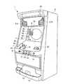
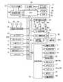
図1は、本発明の第1の実施の形態における遊技機の外観を示す斜視図である。この遊技機は、いわゆる「パチスロ機」である。パチスロ機1は、コイン、メダル、遊技球またはトークンなどの他、遊技者に付与された、もしくは付与される遊技価値の情報を記憶したカードなどの遊技媒体を用いて遊技する遊技機であるが、以下ではメダルを用いるものとして説明する。(First embodiment)
FIG. 1 is a perspective view showing an appearance of a gaming machine according to the first embodiment of the present invention. This gaming machine is a so-called “pachislot machine”. The pachislot
図1に示すように、パチスロ機1の全体を形成しているキャビネット2(筐体に含まれる)の正面には、略垂直面としてのパネル表示部2aが形成されている。このパネル表示部2aの前面には、液晶表示装置5により表示される矩形の液晶表示画面(以下、表示画面ともいう)5aが設けられ、この表示画面5aに液晶表示することができ、かつ液晶の奥側に重ねて配置された円盤(第1円盤301、第2円盤302、第3円盤303(図2参照)に相当する)を透過表示できるようになっている。表示画面5aには、後述する有効ライン8a〜8e、扇形の表示窓4、遊技に関する情報、あるいはアニメーション等による各種の演出が表示されるようになっている。 As shown in FIG. 1, a
表示画面5aの左側には、表示窓4が表示されている。表示窓4には、有効ラインとして水平方向にセンターライン8c、斜め方向にトップライン8b、ボトムライン8d、クロスダウンライン8aおよびクロスアップライン8e(図3参照)が表示される。 A
これらの有効ラインは、後述する1−BETスイッチ11、2−BETスイッチ12、最大BETスイッチ13を操作すること、あるいはメダル投入口22にメダルを投入することにより、それぞれ1本、3本、5本が設定される。どの有効ラインが設定されたかは、後で説明するBETランプ9a、9b、9cが点灯されることで認識される。 These active lines are respectively operated by operating a 1-
ここで、有効ライン8a〜8eは、役の成否に関わる。具体的には、所定の役(例えば、後述の「チェリーの小役」)に対応する1つの図柄(例えば、後述の"チェリー")がセンターライン8cに対応する所定の位置(例えば、表示窓4内の左中段の位置)に停止表示されること、または所定の役に対応する図柄組合せを構成する図柄がいずれかの有効ラインに対応する所定の位置に並んで停止表示されることにより、所定の役が成立することとなる。 Here, the
キャビネット2の内部には、各々の外周面に複数種類の図柄によって構成される図柄列が描かれた3つの円盤301〜303(図4参照)が回転自在に縦一列に設けられている。前述したように、各円盤の図柄は表示窓4を透して目視できるようになっている。各円盤は、定速(例えば、80回転/分)で回転するようになっている。 Inside the
前述の液晶表示画面5aの領域外で、表示窓4の左側には、1−BETランプ9a、2−BETランプ9b、最大BETランプ9c、クレジット表示部19が設けられている。 Outside the area of the liquid
1−BETランプ9a、2−BETランプ9b、最大BETランプ9cは、1つのゲームを行うために賭けられたメダルの数(以下「BET数」という)に応じて点灯する。 The 1-
1−BETランプ9aは、BET数が"1"で1本の有効ラインが設定されたときに点灯する。2−BETランプ9bは、BET数が"2"で3本の有効ラインが設定されたときに点灯する。最大BETランプ9cは、BET数が"3"で全て(5本)の有効ラインが設定されたときに点灯する。 The 1-
クレジット表示部19は、7セグメントLEDからなり、貯留(クレジット)されているメダルの枚数を表示する。前記貯留されているメダルは、遊技者がゲームで獲得し、払出されるべきものを、後述するC/Pスイッチ14の操作により機内に貯留されたものである。この貯留されているメダルの枚数は、所定の記憶領域に記憶されている。 The
表示窓4の右側には、いわゆる当り表示ランプとしてのWINランプ17、払出表示部18およびボーナス遊技情報表示部20が設けられている(図17参照)。 On the right side of the
WINランプ17は、所定の役、例えば「ビッグボーナス(以下、BBと記す)」に当籤した場合に所定の確率で点灯する。ここで、BBおよび「レギュラーボーナス(以下、RBと記す)」を総称して、以下単に「ボーナス」という。BBおよびRBの詳細については、後述する。 The
払出表示部18は、7セグメントLEDからなり、入賞成立時のメダルの払出枚数を表示する。ボーナス遊技情報表示部20は、7セグメントLEDからなり、後で説明するRB遊技状態におけるゲームの回数等を表示する。 The
液晶表示画面5aの下方には、水平面の台座部10が形成されている。台座部10の前側には未使用のスペースがあって、遊技に関する展示物、演出物あるいは遊技者の荷物を載置可能となっている。台座部10の右側に、メダル投入ロ22が設けられており、台座部10の左側には、操作キー24、1−BETスイッチ11、2−BETスイッチ12、最大BETスイッチ13が設けられている。 A
1−BETスイッチ11は、1回の押し操作により、クレジットされているメダルのうち1枚がゲームに賭けられ、2−BETスイッチ12は、1回の押し操作により、クレジットされているメダルのうちの2枚がゲームに賭けられ、最大BETスイッチ13は、1回の押し操作により、1回のゲームに賭けることが可能な最大枚数のメダルが賭けられる。これらのBETスイッチ11、12、13を操作することで、前述のとおり、所定の有効ラインが設定される。 The 1-
操作キー24は、表示画面5aに表示された表示画像の選択操作を行うものである。また、所定の操作を行うことにより、メニュー画面の呼び出し表示を行うものである。 The
台座部10の前面部の右寄りには、遊技者がゲームで獲得したメダルのクレジット(Credit)/払出し(Pay)を押しボタン操作で切り換えるC/Pスイッチ14が設けられている。このC/Pスイッチ14の切り換えにより、クレジットモードまたは払出モードの切り換えが行われる。クレジットモードでは、入賞が成立すると、入賞に対応する払出枚数分のメダルが、クレジットされる。また、払出モードでは、入賞が成立すると、入賞に対応する払出枚数分のメダルが、正面下部のメダル払出口15から払出され、このメダル払出口15から払出されたメダルは、メダル受け部16に溜められる。 A C /
台座部10の前面部中央でC/Pスイッチ14の左側には、3つの円盤301〜303の回転をそれぞれ停止させるための3つの停止ボタン7(左停止ボタン7L、中停止ボタン7C、右停止ボタン7Rに相当する)が設けられている。停止ボタン7の左側には、遊技者の操作により3つの円盤301〜303を回転させ、表示窓4内での図柄の変動表示を開始するためのスタートレバー6が所定の角度範囲で回動自在に取り付けられている。 Three stop buttons 7 (the
パネル表示部2a上方の配当表パネル23の左右には、スピーカ21L、21Rが設けられている。
なお、本実施の形態では、1ゲーム(単位遊技)は、基本的にスタートレバー6が操作されることにより開始し、全ての円盤301〜303が停止したときに終了する。 In the present embodiment, one game (unit game) basically starts when the
また、本実施の形態では、全ての円盤が回転しているときに行われる円盤の停止操作(停止ボタン7L、7C、7Rのいずれかの操作)を「第1停止操作」といい、「第1停止操作」の次に行われる停止操作を「第2停止操作」といい、「第2停止操作」の次に行われる停止操作を「第3停止操作」という。 In the present embodiment, the disk stop operation (operation of any one of the
ここで、図2〜図7により円盤301〜303について説明する。
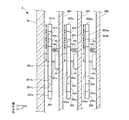
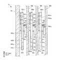
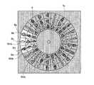
図2は、本発明の第1の実施の形態における円盤機構部の構成を示す断面図である。Here, the
FIG. 2 is a cross-sectional view showing the configuration of the disk mechanism unit in the first embodiment of the present invention.
図2に示すように、3つの円盤301〜303は、透明材料からなる板状の支持部材304〜306に支持されたメインステッピングモータ491〜493の回転軸491a、492a、493aに取り付けられている。回転軸491a、492a、493aは、液晶表示画面5aに対して垂直に配置され、円盤301〜303の盤面は、液晶表示画面5aに対して平行となっている。また、3つの円盤301〜303の外径は同一であって、3つの回転軸491a、492a、493aの軸線は一致している。なお、前記外径は「2(R1+R2+R3+R4)」であり、「R1=R2=R3」となっている。ここでは、3つの円盤301〜303の負荷(例えば、重量、厚さ、外径)を均等とし、同一仕様のメインステッピングモータ491〜493を同一の制御で駆動させている。また、3つの円盤301〜303は、液晶表示画面5aから筐体の奥へ向けて第1円盤301、第2円盤302、第3円盤303の順に重ねて設けられている。したがって、筐体の円盤機構部の厚さは、メインステッピングモータ491〜493の仕様と円盤301〜303および支持部材304〜306の厚さによって規定されることになる。As shown in FIG. 2, the three
第1円盤301は、回転軸491aを中心とした円形の非透過領域301aと、非透過領域301aの周縁の環形の透過領域301c(302c1、301c2に相当する)と、透過領域301cの周縁の環形の図柄領域301bと、を有している(図7参照)。ここで、非透過領域301aの径は「2R4」であり、透過領域301cの幅は「R2+R3」であり、図柄領域301bの幅は「R1」である。The
第2円盤302は、回転軸492aを中心とした円形の非透過領域302a2と、非透過領域302a2の周縁の環形の透過領域302cと、透過領域302cの周縁の環形の図柄領域302bと、図柄領域302bの周縁の環形の非透過領域302a1と、を有している(図6参照)。ここで、非透過領域302a2の径は「2R4」であり、透過領域302cの幅は「R3」である。また、図柄領域302bの幅は「R2」であり、非透過領域302a1の幅は「R1」である。以下、非透過領域302a1、302a2を非透過領域302aともいう。
第3円盤303は、回転軸493aを中心とした円形の非透過領域303a3と、非透過領域303a3の周縁の環形の図柄領域303bと、図柄領域303bの周縁の環形の非透過領域303a2と、非透過領域303a2の周縁の環形の非透過領域303a1と、を有している(図5参照)。ここで、非透過領域303a3の径は「2R4」であり、図柄領域303bの幅は「R3」である。また、非透過領域303a2の幅は「R2」であり、非透過領域303a1の幅は「R1」である。以下、非透過領域303a1、303a2、303a3を非透過領域303aともいう。The
なお、非透過領域301a、302a、303aは、例えば、不透明な樹脂材料で形成されるか、あるいは透明または半透明の樹脂材料で形成された後に着色されたものである。また、図柄領域301b、302b、303bは、例えば、透明または半透明の樹脂材料で形成されたものである。図柄領域301b、302b、303bの表面(液晶表示画面5aに対向する面)には、全周にわたって後述する21個の図柄(図4参照)が等間隔で配置されている。また、図柄領域301b、302b、303bに配置された図柄は、その図柄の種類ごとに大きさが同じである。また、透過領域301c、302cは、透明または半透明の樹脂材料で形成されたものである。また、3つの円盤301〜303は同一材料で一体形成しても良い。あるいは異なる材料で形成しても良い。 The
そして、図柄領域の外径は、第3円盤303の図柄領域303b、第2円盤302の図柄領域302b、第1円盤301の図柄領域301bの順に大きくなっている。また、3つの図柄領域301b、302b、303bの幅は同一(R1=R2=R3)となっている。第3円盤303の図柄領域303bと液晶表示画面5aの間には、同一幅の第1円盤301の透過領域301c2および第2円盤302の透過領域302cが介在し、第2円盤302の図柄領域302bと液晶表示画面5aの間には、同一幅の第1円盤301の透過領域301c1が介在しているため、液晶表示画面5a上の表示窓4には、第1円盤301の透過領域301cを介して第3円盤303の図柄領域303bおよび第2円盤302の図柄領域302bが透過表示されるとともに、第1円盤301の図柄領域301bが透過表示されることになる。The outer diameter of the symbol area increases in the order of the
また、3つの円盤301〜303の回転位置(図柄位置)を検出するため、3つの支持部材304〜306におけるメインステッピングモータ491〜493の取り付け面には、例えば、発光部と受光部を備えた反射式のフォトセンサ50a、50b、50cが設けられている。一方、3つの円盤301〜303の非透過領域301a、302a、303aの裏面(前記取り付け面との対向面)には、円盤の回転に応じて前記受光部を遮る位置にスタートインデックスとしての遮蔽片50d、50e、50fが設けられている。フォトセンサ50a、50b、50cは、円盤301〜303の回転にしたがって遮蔽片50d、50e、50fの通過を検出し、パルス信号を発生するようになっている。このパルス信号を基準として、メインステッピングモータ491〜493の駆動パルス数を計数することにより、計数結果に基づいて遮蔽片50d、50e、50fからの変位を検出することができる。 In addition, in order to detect the rotational positions (symbol positions) of the three
図3は、本発明の第1の実施の形態における液晶表示画面5aに表示された表示窓4を示す図である。 FIG. 3 is a diagram showing the
図3に示すように、液晶表示画面5aにおいて、表示窓4に相当する領域のみ光を透過させることにより、円盤301〜303の図柄領域301b、302b、303bの一部を透視可能としている。表示窓4は、図柄領域301b、302b、303bに配された図柄の3コマ分が透過表示されるよう、略扇形としている。また、表示窓4には、賭け数に応じて前述の有効ライン8a〜8eが表示されるようになっている。有効ラインのうち、水平方向にセンターライン8cが表示され、斜め方向にはトップライン8b、ボトムライン8d、クロスダウンライン8a、クロスアップライン8eが表示される。本実施の形態では、環形の図柄領域301b、302b、303bの左側の一部が表示窓4と重なるよう、表示窓4を透過表示するとともに有効ライン8a〜8eを表示している。また、表示窓4に表示される図柄の上下方向が揃うよう、図柄領域301b、302b、303bの図柄を配列している。表示窓4においては、3つの円盤301〜303の回転に伴い、3つの図柄列が略上下方向に変動するため、3つのリールの図柄列を変動させるパチスロ機に慣れた遊技者も違和感なく遊技を行うことができる。 As shown in FIG. 3, in the liquid
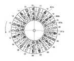
図4は、本発明の第1の実施の形態における3つの円盤301〜303の図柄領域301b、302b、303bを示す図である。図5は、本発明の第1の実施の形態における第3円盤303を示す図である。図6は、本発明の第1の実施の形態における第2円盤302を示す図である。図7は、本発明の第1の実施の形態における第1円盤301を示す図である。 FIG. 4 is a diagram showing the
本実施の形態では、前述のように操作方向(図2参照)の手前から第1円盤301、第2円盤302、第3円盤303の順に3つの円盤が重なり、図柄領域303b、図柄領域302b、図柄領域301bの順に外径が大きくなるため、図4に示すように、3つの図柄領域301b、302b、303bが同心のリングとして円盤の中心(回転軸491a、492a、493aに相当する)から径方向に広がることになる。なお、3つの図柄領域301b、302b、303bの図柄同士が重なることはない。 In the present embodiment, as described above, the three disks overlap in the order of the
また、図5〜図7に示すように、第1円盤301の図柄領域301b、第2円盤302の図柄領域302b、第3円盤303の図柄領域303bには、全周にわたって複数種類の図柄が21個配列された図柄列が形成されている。各図柄には"00"〜"20"のコードナンバーが付され、後で説明するROM32(図17参照)に格納(記憶)されている。 Further, as shown in FIGS. 5 to 7, in the
3つの図柄領域301b、302b、303bのそれぞれには、"赤7"、"BAR"、"リプレイ"、"チェリー"、"プラム"、"ベル"および"スイカ"の図柄で構成される図柄列が表わされている。3つの円盤301〜303は、図柄領域301b、302b、303bが図中矢印方向に移動するように回転駆動される。 Each of the three
前記図柄列は、例えば、印刷加工によって図柄領域301b、302b、303bに形成されている。ここで、図柄領域301b、302b、303bは、円盤301〜303の回転軸に対して垂直に配されているため、印刷加工された前記図柄列が遠心力によって剥離することを回避し、パチスロ機1の耐久性を向上させることになる。なお、通常の円筒状のリール機構を用いた場合には、図柄列が印刷された短冊状のシート部材をリールの外周に装着する(例えば、貼着する)ことになるため、リールの回転による遠心力によって前記シート部材の端部継ぎ目部分がリールから剥離することがありうる。 The symbol row is formed in the
図8は、本発明の第1の実施の形態における図柄組合せテーブルを示す図である。 FIG. 8 is a diagram showing a symbol combination table according to the first embodiment of the present invention.
パチスロ機1においては、遊技者によりスタートレバー6が操作されると、内部抽籤を行い、内部当籤役(例えば、「ベルの小役」、「リプレイ」、「BB1」等)を決定する。そして、遊技者の停止操作により、3つの円盤301〜303を停止させ、遊技者が指定した有効ライン8上に、前記内部当籤役に対応する図柄組合せが停止表示されれば、表示役の成立となる。 In the
ここで、表示役のうち、特に、内部当籤役に対応する図柄組合せが有効ライン上に停止表示されたとき払出しのあるものを「入賞役」とする。内部当籤役に対応する図柄組合せが有効ライン上に停止表示されたとき払出しのないものは、「当籤役の成立」とする。 Here, among the displayed winning combinations, in particular, a winning combination is a winning combination when the symbol combination corresponding to the internal winning combination is stopped and displayed on the active line. When the symbol combination corresponding to the internal winning combination is stopped and displayed on the active line, the winning combination is “successful winning combination”.
図8に示すように、有効ラインに沿って図柄の組合せ"チェリー−ANY−ANY"(ANYはどの図柄でも良い)が並ぶことにより、「チェリーの小役」に入賞し、メダル投入枚数が"1"または"2"の場合には、15枚のメダルが払出され、メダル投入枚数が"3"の場合には、4枚のメダルが払出される。なお、投入枚数が3枚である、すなわち、有効ラインが5本設定されている場合に、赤チェリーが表示窓4の上段または下段に表示されると、2つの有効ライン上で成立することとなるので、8枚(4枚×2)のメダルの払出しが行われる。 As shown in FIG. 8, the symbol combination “CHERRY-ANY-ANY” (ANY may be any symbol) along the active line will win the “Cherry small role” and the number of medals inserted will be “ In the case of “1” or “2”, 15 medals are paid out, and in the case where the number of inserted medals is “3”, 4 medals are paid out. In addition, when the number of inserted sheets is 3, that is, when five effective lines are set, if red cherry is displayed on the upper or lower stage of the
また、有効ラインに沿って図柄の組合せ"ベル−ベル−ベル"が並ぶことにより、「ベルの小役」に入賞し、メダル投入枚数に関わりなく、15枚のメダルが払出される。 In addition, the symbol combination “Bell-Bell-Bell” is arranged along the active line, so that “Bell's small role” is won, and 15 medals are paid out regardless of the number of medals inserted.
また、有効ラインに沿って図柄の組合せ"スイカ−スイカ−スイカ"が並ぶことにより、「スイカの小役」に入賞し、メダル投入枚数に関わりなく、8枚のメダルが払出される。 In addition, the combination of symbols “watermelon-watermelon-watermelon” is arranged along the active line, so that the “watermelon small part” is won and eight medals are paid out regardless of the number of medals inserted.
また、有効ラインに沿って図柄の組合せ"プラム−プラム−プラム"が並ぶことにより、「プラムの小役」に入賞し、メダル投入枚数に関わりなく、4枚のメダルが払出される。 In addition, the symbol combination “Plum-Plum-Plum” is arranged along the active line, so that “Plum Minor” is won and four medals are paid out regardless of the number of medals inserted.
前記「チェリーの小役」、「ベルの小役」、「スイカの小役」、「プラムの小役」を「小役」と総称する場合もある。 The “cherry small part”, “bell small part”, “watermelon small part”, and “plum small part” may be collectively referred to as “small part”.
また、有効ラインに沿って図柄の組合せ"リプレイ−リプレイ−リプレイ"が並ぶことにより、「リプレイ」が成立する。「リプレイ」が成立すると、投入したメダルの枚数と同数のメダルが自動投入されるので、遊技者は、メダルを消費することなく次のゲームを行うことができる。すなわち、「リプレイ」は、成立することにより遊技価値の投入をすることによらずに遊技を行うことができる表示役である。 Further, “replay” is established by arranging the symbol combination “replay-replay-replay” along the active line. When “Replay” is established, the same number of medals as the number of inserted medals are automatically inserted, so that the player can play the next game without consuming the medals. In other words, “replay” is a display role that allows a game to be played without establishing a game value when established.
また、有効ラインに沿って図柄の組合せ"赤7−赤7−赤7"が並ぶことにより、「BB1」が成立して、メダルは払出されないが、次のゲームの遊技状態が「RB遊技状態」(より具体的には、BB作動中フラグが"オン"となり、RB作動時処理によりRB遊技状態)となる。遊技状態については、後述する。 Further, by arranging the symbol combination “red 7-red 7-
また、有効ラインに沿って図柄の組合せ"BAR−BAR−BAR"が並ぶことにより、「BB2」が成立して、メダルは払出されないが、次のゲームの遊技状態が「RB遊技状態」(より具体的には、BB作動中フラグが"オン"となり、RB作動時処理によりRB遊技状態)となる。 In addition, when the symbol combination “BAR-BAR-BAR” is arranged along the active line, “BB2” is established and the medal is not paid out, but the gaming state of the next game is “RB gaming state” (from More specifically, the BB operating flag is turned “ON”, and the RB operating state is set by the RB operating process.
また、前記「チェリーの小役」、「ベルの小役」、「スイカの小役」、「プラムの小役」、「リプレイ」、「BB1」および「BB2」に係る図柄の組合せ以外の図柄の組合せが表示されると、「ハズレ」が成立する。 In addition, symbols other than the combinations of symbols related to the “cherry small part”, “bell small part”, “watermelon small part”, “plum small part”, “replay”, “BB1” and “BB2” When the combination is displayed, “losing” is established.
図9は、本発明の第1の実施の形態におけるボーナス作動時テーブルを示す図である。ボーナス作動時テーブルには、ボーナスが成立したときに設定する各種情報設定値が記載されている。 FIG. 9 is a diagram showing a bonus operating time table according to the first embodiment of the present invention. In the bonus operation time table, various information setting values set when the bonus is established are described.
図9に示すように、表示役「BB1」が成立し、BB作動時処理が発動されたときには、作動中フラグとして"BB1作動中フラグ"をたて、ボーナス終了枚数カウンタに"465"を設定する。 As shown in FIG. 9, when the display combination “BB1” is established and the processing at the time of BB operation is activated, “BB1 operating flag” is set as the operating flag, and “465” is set in the bonus end number counter. To do.
また、表示役「BB2」が成立し、BB作動時処理が発動されたときには、作動中フラグとして"BB2作動中フラグ"をたて、ボーナス終了枚数カウンタに"350"を設定する。 Further, when the display combination “BB2” is established and the BB operation process is activated, the “BB2 operating flag” is set as the operating flag, and “350” is set in the bonus end number counter.
さらに、ボーナス作動監視処理により、RB作動時処理が発動されたときには、作動中フラグとして"RB作動中フラグ"をたて、遊技可能回数カウンタに"12"を、入賞可能回数カウンタに"8"を設定する。 Further, when the RB operation time process is activated by the bonus operation monitoring process, the “RB operation flag” is set as the operating flag, “12” is set in the possible game number counter, and “8” is set in the possible winning number counter. Set.
ここで、遊技状態について説明する。遊技状態とは、そのゲームあるいは何回かのゲームの間の遊技状態を示すもので、基本となる「一般遊技状態」と、遊技者に有利な「RB遊技状態」とがある。 Here, the gaming state will be described. The gaming state indicates a gaming state during the game or during several games, and includes a basic “general gaming state” and an “RB gaming state” advantageous to the player.
「RB遊技状態」とは、内部抽籤の際にメダルを獲得できる当籤役に当籤しやすい内部抽籤テーブルが選択される遊技状態であり、遊技者にとって有利な遊技状態となっている。「内部抽籤テーブル」については、後述する。 The “RB gaming state” is a gaming state in which an internal lottery table that is easy to win a winning combination that can acquire medals at the time of internal lottery is selected, and is a gaming state that is advantageous to the player. The “internal lottery table” will be described later.
また、「RB遊技状態」は終了条件が規定されている。本実施の形態においては、1回の「RB遊技状態」において可能な最大のゲーム数(これを「RB遊技可能回数」という)は、12回である。また、この「RB遊技状態」において、メダルの払出しが行われる入賞役を成立させることができる回数(これを「RB入賞可能回数」という)は、8回までである。すなわち、この「RB遊技状態」は、ゲーム数が12回に達するか、または入賞役の成立回数が8回に達した場合に終了する。 Further, the “RB gaming state” has an end condition. In the present embodiment, the maximum number of games that can be performed in one “RB gaming state” (this is referred to as the “number of possible RB games”) is twelve. Further, in this “RB gaming state”, the number of times that a winning combination in which medals are paid out can be established (this is referred to as “RB winning number”) is up to eight times. In other words, this “RB gaming state” ends when the number of games reaches 12 times or the winning combination is reached 8 times.
さらに、「RB遊技状態」は、ボーナス中(具体的には、BB作動中フラグが"オン"の状態のとき)に発生する遊技状態であるが、ボーナスの終了条件も規定されている。本実施の形態においては、ボーナスを終了させる払出枚数が、「BB1」により作動された場合には"465"枚、「BB2」により作動された場合には"350"枚と規定されている。すなわち、ボーナス(BB作動中フラグが"オン"の状態)は、払出枚数が"465"枚、あるいは、"350"枚に達した場合に終了する。 Furthermore, the “RB gaming state” is a gaming state that occurs during a bonus (specifically, when the BB operating flag is in the “on” state), but a bonus termination condition is also defined. In this embodiment, the number of payouts for ending the bonus is defined as “465” when operated by “BB1”, and “350” when operated by “BB2”. That is, the bonus (the state where the BB operation flag is “on”) is ended when the payout number reaches “465” or “350”.
また、前述のように「一般遊技状態」とは、遊技者に有利な特典がない基本的な遊技状態である。 Further, as described above, the “general gaming state” is a basic gaming state in which there is no privilege advantageous to the player.
さらに、「一般遊技状態」において、「BB1」(ボーナスの作動に係る内部当籤役)に内部当籤したが、設定された有効ライン上に「BB1」の図柄組合せが表示させられなかった場合、内部当籤した「BB1」を次回以降のゲームに持ち越す。「BB1」に内部当籤すると、「BB1」の図柄の組合せが、設定された有効ライン上に表示されるまでの間、「BB1」を「持越役」として記憶する。「BB1」が「持越役」として記憶されている間、「持ち越し状態」が継続する。 Furthermore, in the “general gaming state”, when “BB1” (internal winning combination related to the operation of the bonus) is won internally, but the symbol combination “BB1” is not displayed on the set active line, The winning “BB1” is carried over to the next game. When “BB1” is won internally, “BB1” is stored as a “carryover” until the symbol combination “BB1” is displayed on the set active line. While “BB1” is stored as “carry-over”, the “carry-over state” continues.
同様に、「一般遊技状態」において、「BB2」(ボーナスの作動に係る内部当籤役)に内部当籤したが、設定された有効ライン上に「BB2」の図柄組合せが表示させられなかった場合も、内部当籤した「BB2」を次回以降のゲームに持ち越し、「BB2」の図柄の組合せが、設定された有効ライン上に表示されるまでの間、「BB2」を「持越役」として記憶する。「BB2」が「持越役」として記憶されている間も、「持ち越し状態」が継続する。 Similarly, in the “general gaming state”, “BB2” (internal winning combination related to the operation of the bonus) is won internally, but the symbol combination “BB2” is not displayed on the set active line. The internal winning “BB2” is carried over to the next and subsequent games, and “BB2” is stored as a “carryover combination” until the symbol combination “BB2” is displayed on the set active line. The “carry-over state” continues while “BB2” is stored as “carry-over”.
ここで、BB作動中フラグが"オン"に更新されてから"オフ"に更新されるまでのBB作動中フラグとRB作動中フラグとの関係について説明する。BBが成立した場合に、BB作動中フラグが"オン"に更新される。このBB作動中フラグが"オン"に更新されたことを契機にRB作動中フラグが"オン"に更新される。そして、遊技可能回数が0になるか、または入賞可能回数が0になると、RB作動中フラグが"オフ"に更新される。BB作動中フラグが"オフ"に更新されるまでRB遊技状態となる。 Here, the relationship between the BB operating flag and the RB operating flag from when the BB operating flag is updated to “on” to when it is updated to “off” will be described. When BB is established, the BB operating flag is updated to “ON”. When the BB operating flag is updated to “ON”, the RB operating flag is updated to “ON”. When the possible number of games becomes 0 or the possible number of wins becomes 0, the RB operating flag is updated to “off”. The RB gaming state is maintained until the BB operating flag is updated to “off”.
BB作動中フラグが"オフ"に更新される条件を充足した場合に、BB作動中フラグが"
オフ"に更新されるが、このBB作動中フラグが"オフ"に更新されたことを契機にRB作
動中フラグが"オフ"に更新される。したがって、BB作動中フラグが"オン"であるときは、RB作動中フラグが"オン"に更新される。すなわち、BB成立後は、BB作動中フラグがオフに更新されるまでRB遊技状態となる。When the condition that the BB operating flag is updated to “off” is satisfied, the BB operating flag is “
Although the BB operating flag is updated to “OFF”, the RB operating flag is updated to “OFF”. Therefore, the BB operating flag is “ON”. At this time, the RB operating flag is updated to “ON.” That is, after BB is established, the RB gaming state is maintained until the BB operating flag is updated to OFF.
また、「BB1」および「BB2」が「持越役」として持ち越されている状態を、BB内部当籤状態(BB持ち越し状態)ともいう。 Further, a state where “BB1” and “BB2” are carried over as “carry-over” is also referred to as a BB internal winning state (BB carry-over state).
図10は、本発明の第1の実施の形態における内部抽籤テーブル決定テーブルを示す図である。内部抽籤テーブル決定テーブルは、内部抽籤処理において、遊技状態に基づいて内部抽籤テーブルの種別と抽籤回数を決定するために用いられる。 FIG. 10 is a diagram illustrating an internal lottery table determination table according to the first embodiment of this invention. The internal lottery table determination table is used to determine the type of the internal lottery table and the number of lotteries based on the gaming state in the internal lottery process.
すなわち、内部抽籤テーブル決定テーブルは、遊技状態に応じて選択する内部抽籤テーブルと、その内部抽籤テーブルを用いて何回まで抽籤を行うかを示す抽籤回数と、が規定されたものである。ここで、抽籤回数とは、内部抽籤処理に先立って取得された乱数値と、当籤番号ごとに設定された上限値および下限値を用いて行われる抽籤処理の回数を示している。内部当籤役は、この内部抽籤処理により求められる当籤番号にしたがって決定されることになる。 In other words, the internal lottery table determination table defines an internal lottery table to be selected according to the gaming state and the number of lotteries indicating how many lotteries are to be performed using the internal lottery table. Here, the number of lotteries indicates the number of lottery processes performed using the random number value obtained prior to the internal lottery process and the upper limit value and the lower limit value set for each winning number. The internal winning combination is determined according to the winning number determined by the internal lottery process.
図10に示すように、一般遊技状態では、内部抽籤テーブルとして一般遊技状態用内部抽籤テーブルが決定されるとともに、抽籤回数として"7"が決定される。RB遊技状態では、内部抽籤テーブルとしてRB遊技状態用内部抽籤テーブルが決定されるとともに、抽籤回数として"4"が決定される。 As shown in FIG. 10, in the general gaming state, the internal lottery table for the general gaming state is determined as the internal lottery table, and “7” is determined as the number of lotteries. In the RB gaming state, the internal lottery table for the RB gaming state is determined as the internal lottery table, and “4” is determined as the number of lotteries.
次に、内部抽籤テーブルについて説明する。図11は、本発明の第1の実施の形態における一般遊技状態用内部抽籤テーブルを示す図である。図12は、本発明の第1の実施の形態におけるRB遊技状態用内部抽籤テーブルを示す図である。双方の内部抽籤テーブルは、内部抽籤処理において、当籤番号と投入枚数に基づいて抽籤値を取得するために用いられる。 Next, the internal lottery table will be described. FIG. 11 is a diagram showing an internal lottery table for a general gaming state according to the first embodiment of the present invention. FIG. 12 is a diagram showing an RB gaming state internal lottery table according to the first embodiment of the present invention. Both internal lottery tables are used for acquiring lottery values based on the winning number and the number of inserted sheets in the internal lottery process.
図11、図12に示すように、内部抽籤テーブルには、当籤番号と、この当籤番号ごとに投入枚数にしたがった抽籤値となる乱数値の下限値と上限値が示されている。各抽籤値の幅を"65536"で除したものが、該当する内部当籤役の当籤確率となる。いずれの当籤番号の乱数値幅にも該当しない範囲は、"ハズレ"となる。また、本実施の形態では、「一般遊技状態用内部抽籤テーブル」、「RB遊技状態用内部抽籤テーブル」の2つの内部抽籤テーブルを用いる。 As shown in FIGS. 11 and 12, the internal lottery table shows a winning number, and a lower limit value and an upper limit value of random numbers that become lottery values according to the number of pieces inserted for each winning number. A value obtained by dividing the range of each lottery value by “65536” is the winning probability of the corresponding internal winning combination. The range that does not correspond to the random number range of any winning number is “lost”. Further, in the present embodiment, two internal lottery tables, “general gaming state internal lottery table” and “RB gaming state internal lottery table” are used.
図11の一般遊技状態用内部抽籤テーブルは、前述のように一般遊技状態で用いられる。また、ここでは、投入枚数ごとに当籤番号と、抽籤値の下限値と上限値と、が対応付けられている。この一般遊技状態用内部抽籤テーブルに基づいて、当籤番号として"1"〜"7"のいずれかに決定される可能性があり、いずれの抽籤値の下限値と上限値との範囲内にもないときには、当籤番号は"0"となる。 The general game state internal lottery table of FIG. 11 is used in the general game state as described above. Further, here, the winning number is associated with the lower limit value and the upper limit value of the lottery value for each inserted number. Based on this internal gaming state internal lottery table, the winning number may be determined as any one of “1” to “7”, and within the range between the lower limit value and the upper limit value of any lottery value. If not, the winning number is “0”.
図12のRB遊技状態用内部抽籤テーブルは、前述のようにRB遊技状態で用いられる。このRB遊技状態用内部抽籤テーブルに基づいて、当籤番号として"1"〜"4"のいずれかに決定される可能性があり、いずれの抽籤値の下限値と上限値との範囲内にもないときには、当籤番号は"0"となる。 The RB gaming state internal lottery table of FIG. 12 is used in the RB gaming state as described above. Based on this RB gaming state internal lottery table, the winning number may be determined as any one of “1” to “4”, and within the range between the lower limit value and the upper limit value of any lottery value. If not, the winning number is “0”.
ここで、内部抽籤テーブルは、複数段階(例えば、6段階)設けられた設定値(設定)ごとに設けられるが、設定値ごとの内部抽籤テーブルは省略する。設定値は、基本的に遊技店側が設定(選択)する値であり、設定値に応じて遊技における遊技者の有利さの度合い(例えば、出玉率、役の内部当籤確率など)が異なるようになっている。実際には、設定値として"1"〜"6"を設けるようにしている。そして、「RB」などの役に内部当籤する確率が、設定値の間で異なるようにしている。また、全ての設定値ごとに遊技状態に応じた内部抽籤テーブルを用意するのではなく、設定値間で同一の内部抽籤テーブルを共用しても良い。このとき、同一の遊技状態で共用しても良いし、異なる遊技状態で共用することもできる。このような内部抽籤テーブルの設定は、前述の内部抽籤テーブル決定テーブルにより、容易に行うことができる。 Here, the internal lottery table is provided for each set value (setting) provided in a plurality of stages (for example, six stages), but the internal lottery table for each set value is omitted. The set value is basically a value set (selected) by the game store side, and the degree of player's advantage in the game (for example, the winning rate, the internal winning probability of the combination, etc.) varies depending on the set value. It has become. Actually, “1” to “6” are provided as set values. Then, the probability of internally winning a role such as “RB” is made different between the set values. Further, instead of preparing an internal lottery table corresponding to the gaming state for every set value, the same internal lottery table may be shared among the set values. At this time, it may be shared in the same gaming state, or can be shared in different gaming states. Such setting of the internal lottery table can be easily performed by the above-mentioned internal lottery table determination table.
図13は、本発明の第1の実施の形態における内部当籤役決定テーブルを示す図である。内部当籤役決定テーブルは、前述の内部抽籤処理により求められた当籤番号にしたがって内部当籤役を決定するものである。ここで、内部当籤役は、8ビットのビット列で表される。 FIG. 13 is a diagram showing an internal winning combination determination table in the first embodiment of this invention. The internal winning combination determination table is for determining an internal winning combination in accordance with the winning number obtained by the internal lottery process. Here, the internal winning combination is represented by an 8-bit bit string.
図13に示すように、当籤番号が"0"のときには、内部当籤役として"0000000
0"が決定され、これは"ハズレ"のことである。当籤番号が"1"のときには、内部当籤役
として"00000001"が決定され、これは"チェリー"のことである。当籤番号が"2"のときには、内部当籤役として"00000010"が決定され、これは"ベル"のことである。As shown in FIG. 13, when the winning number is “0”, “0000000” is given as the internal winning combination.
“0” is determined, which means “losing.” When the winning number is “1”, “00000001” is determined as the internal winning combination, which is “Cherry”. In the case of “2”, “00000010” is determined as the internal winning combination, which is “Bell”.
当籤番号が"3"のときには、内部当籤役として"00000100"が決定され、これは"スイカ"のことである。当籤番号が"4"のときには、内部当籤役として"00001000"が決定され、これは"プラム"のことである。当籤番号が"5"のときには、内部当籤役として"00010000"が決定され、これは"リプレイ"のことである。 When the winning number is “3”, “00000100” is determined as the internal winning combination, which is “watermelon”. When the winning number is “4”, “00001000” is determined as the internal winning combination, which is “Plum”. When the winning number is “5”, “00010000” is determined as the internal winning combination, which is “replay”.
当籤番号が"6"のときには、内部当籤役として"00100000"が決定され、これは"BB1"のことである。当籤番号が"7"のときには、内部当籤役として"01000000"が決定され、これは"BB2"のことである。 When the winning number is “6”, “00100000” is determined as the internal winning combination, which is “BB1”. When the winning number is “7”, “01000000” is determined as the internal winning combination, which is “BB2”.
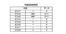
図14は、本発明の第1の実施の形態におけるボーナスチェックデータを示す図である。図14に示すように、ボーナスチェックデータは、8ビットで"01100000"となっている。 FIG. 14 is a diagram showing bonus check data in the first embodiment of the present invention. As shown in FIG. 14, the bonus check data is “01100000” in 8 bits.
ボーナスチェックデータは、内部抽籤処理において、内部当籤役との論理演算(論理積演算)に用いられ、内部当籤役からボーナスデータのみを抽出させるものである。具体的には、ボーナスチェックデータ"01100000"と内部当籤役との論理積演算により、内部当籤役が"00100000"および"01000000"のとき、ビット5、ビット6の"1"が有効となるので、内部当籤役が「BB1」および「BB2」のときのみボーナスデータとして抽出される。 The bonus check data is used for a logical operation (logical product operation) with an internal winning combination in the internal lottery process, and only bonus data is extracted from the internal winning combination. Specifically, when the internal winning combination is “00100000” and “01000000” by the logical product operation of the bonus check data “01100000” and the internal winning combination, “1” of
図15は、本発明の第1の実施の形態における内部当籤役(または表示役)の格納領域を示す図である。この格納領域は、RAM33の所定の記憶領域に割り当てられている。ここでは、格納された各ビットデータの種別(ビット0〜ビット6)と当該ビットデータとして設定される値(0または1)とが対応付けられている。ここで、ビット7は、未使用の格納領域である。 FIG. 15 is a diagram showing a storage area of an internal winning combination (or display combination) in the first embodiment of the present invention. This storage area is allocated to a predetermined storage area of the
また、内部当籤役格納領域は、内部抽籤処理において、内部当籤役と持越役格納領域の格納データの論理和が格納されるものである。 The internal symbol combination storage area stores the logical sum of the data stored in the internal symbol combination and carryover combination storage area in the internal lottery process.
図16は、本発明の第1の実施の形態における持越役格納領域を示す図である。この持越役格納領域も、RAM33の所定の記憶領域に割り当てられている。ここで、ビット0〜ビット4、およびビット7は、未使用の格納領域である。 FIG. 16 is a diagram showing a carryover combination storage area in the first embodiment of the present invention. This carryover combination storage area is also allocated to a predetermined storage area of the
また、持越役格納領域は、同じく内部抽籤処理において、内部当籤役とボーナスチェックデータの論理積と、持越役格納領域のデータとの論理和が格納されるものである。 In addition, the carryover combination storage area stores the logical sum of the logical product of the internal winning combination and bonus check data and the data of the carryover combination storage area in the internal lottery process.
次に、本発明の第1の実施の形態におけるパチスロ機1の回路構成を説明する。 Next, the circuit configuration of the
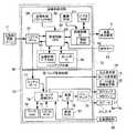
図17は、パチスロ機1における遊技処理動作を制御する主制御回路71と、主制御回路71に電気的に接続する周辺装置(アクチュエータ)と、主制御回路71から送信される制御信号(コマンド)に基づいて液晶表示装置5およびスピーカ21L、21R等を制御する副制御回路72と、を含む電気回路の構成を示すブロック図である。 FIG. 17 shows a
主制御回路71は、回路基板上に配置されたマイクロコンピュータ30を主たる構成要素とし、これに乱数サンプリングのための回路を加えて構成されている。マイクロコンピュータ30は、あらかじめ設定されたプログラムにしたがって制御動作を行うCPU31と、記憶手段であるROM32およびRAM33を備えている。 The
CPU31には、基準クロックパルスを発生するクロックパルス発生回路34および分周器35と、抽出(サンプリング)される乱数を発生する乱数発生器36およびサンプリング回路37とが接続されている。 Connected to the
なお、乱数サンプリングのための手段として、マイクロコンピュータ30内で、すなわち、CPU31の動作プログラム上で、乱数サンプリングを実行するように構成しても良い。その場合、乱数発生器36およびサンプリング回路37は省略可能であり、あるいは、乱数サンプリング動作のバックアップ用として残しておくことも可能である。 In addition, as a means for random number sampling, you may comprise so that random number sampling may be performed within the
マイクロコンピュータ30のROM32には、CPU31の処理に係るプログラム、スタートレバー6を操作(スタート操作)するごとに行われる乱数サンプリングの判定に用いられる「内部抽籤テーブル」、ボーナスが成立したときに設定する各種情報設定値が規定された「ボーナス作動時テーブル」、停止ボタンの操作に応じて円盤の停止態様を決定するための「停止制御テーブル(図示せず)」、副制御回路72に送信するための各種制御指令(コマンド、信号)などが記憶されている。 In the
RAM33には、種々の情報が格納される。例えば、抽出した乱数値、各種フラグ(例えば、BB作動中フラグ、RB作動中フラグ)、メダルのクレジット枚数、遊技状態の情報などが格納される。 Various information is stored in the
また、副制御回路72が主制御回路71へコマンド、情報などを入力することはなく、主制御回路71から副制御回路72への一方向で通信が行われる。 Further, the
マイクロコンピュータ30からの制御信号により動作が制御される主要なアクチュエータとしては、メダルを収納しホッパー駆動回路41の命令により所定枚数のメダルを払出すホッパー(払出しのための駆動部を含む)40、円盤301〜303を回転駆動するメインステッピングモータ491、492、493などがある。 As a main actuator whose operation is controlled by a control signal from the
さらに、メインステッピングモータ491、492、493を駆動制御するモータ駆動回路39およびホッパー40を駆動制御するホッパー駆動回路41がCPU31の出力部に接続されている。これらの駆動回路は、それぞれCPU31から出力される駆動指令などの制御信号を受けて、各アクチュエータの動作を制御する。なお、モータ駆動回路39は、メインステッピングモータ491、492、493を任意の速度で回転させる。 Further, a
また、マイクロコンピュータ30が制御指令を発生するために必要な入力信号を発生する主な入力信号発生手段としては、スタートスイッチ6S、1−BETスイッチ11、2−BETスイッチ12、最大BETスイッチ13、C/Pスイッチ14、投入メダルセンサ22S、円盤停止信号回路46、円盤位置検出回路50、払出完了信号回路51があり、これらもCPU31に接続されている。 The main input signal generating means for generating an input signal necessary for the
スタートスイッチ6Sは、スタートレバー6の操作を検出してスタートスイッチ信号を発生する。投入メダルセンサ22Sは、メダル投入口22に投入されたメダルを検出する。 The
CPU31は、投入メダルセンサ22Sがメダル投入口22に投入されたメダルを検出すると、このメダルをカウントしてRAM33に最大50枚のメダルをクレジットするようになっており、CPU31は、RAM33にクレジットされたメダルを1−BETスイッチ11、2−BETスイッチ12、最大BETスイッチ13の操作に応じた枚数だけ減算し、有効ライン8a〜8eを設定し、BETランプ9a、9b、9cを点灯させるようになっている。 When the inserted
円盤停止信号回路46は、各停止ボタン7L、7C、7Rの操作に応じて停止信号を発生する。円盤位置検出回路50は、円盤回転センサ(図2の50a、50b、50cに相当する)からのパルス信号を受けて各円盤上の図柄の位置を検出するための信号をCPU31に供給する。払出完了信号回路51は、メダル検出部40Sの計数値(ホッパー40から払出されたメダルの枚数)が指定された枚数データに達した時、メダル払出完了を検知するための信号を発生する。 The disk
乱数発生器36は、一定の数値範囲(0〜65535)に属する乱数値を発生し、サンプリング回路37は、スタートレバー6が操作された後の適宜のタイミングで1個の乱数値をサンプリングする。こうしてサンプリングされた乱数値およびROM32内に格納されている内部抽籤テーブルに基づいて、内部当籤役が決定される。 The
円盤301〜303の回転が開始された後、メインステッピングモータ491、492、493の各々に供給される駆動パルスの数が計数され、その計数値はRAM33の所定エリアに書き込まれる。円盤301〜303の機構部からは一回転ごとにリセットパルスが得られ、これらのパルスは円盤位置検出回路50を介してCPU31に入力される。こうして得られたリセットパルスにより、RAM33で計数されている駆動パルスの計数値が"0"にクリアされる。これにより、RAM33内には、各円盤について一回転の範囲内における回転位置に対応した計数値が格納される。 After the rotation of the
円盤301〜303の回転位置と円盤外周面上に描かれた図柄とを対応付けるために、図柄テーブル(図示せず)がROM32内に格納されている。この図柄テーブルでは、前述したリセットパルスが発生する回転位置を基準として、各円盤の一定の回転ピッチごとに順次付与されるコードナンバー(図柄位置に相当する)と、それぞれのコードナンバーごとに対応して設けられた図柄を示す図柄コードとが対応付けられている。 A symbol table (not shown) is stored in the
さらに、ROM32内には、図柄組合せテーブル(図8参照)が格納されている。この図柄組合せテーブルでは、表示役となる図柄の組合せと、表示役のメダル払出枚数と、その表示役を表わす表示役判定コードとが対応付けられている。前記図柄組合せテーブルは、第1円盤301、第2円盤302、第3円盤303の停止制御時、および全円盤301〜303の停止後の表示役確認を行う場合に参照される。 Further, a symbol combination table (see FIG. 8) is stored in the
前記乱数サンプリングに基づく抽籤処理(内部抽籤処理)に基づいて、CPU31は、遊技者が停止ボタン7L、7C、7Rを操作したタイミングで円盤停止信号回路46から送られる円盤停止信号、および選択された「停止制御テーブル」に基づいて、円盤301〜303を停止制御する信号をモータ駆動回路39に送る。 Based on the lottery process (internal lottery process) based on the random number sampling, the
内部当籤後、入賞を示す停止態様となれば、CPU31は、C/Pスイッチ14により設定されたモードに応じて、RAM33にセットされたクレジットカウンタの更新、または、払出指令信号をホッパー駆動回路41に供給してホッパー40から所定枚数のメダルの払出しを行う。その際、メダル検出部40Sは、ホッパー40から払出されるメダルの枚数を計数し、その計数値が指定された数に達した時に、メダル払出完了信号がCPU31に入力される。これにより、CPU31は、ホッパー駆動回路41を介してホッパー40の駆動を停止し、「メダル払出処理」を終了する。 If it becomes a stop mode indicating winning after the internal winning, the
図18は、本発明の第1の実施の形態における副制御回路72のブロック図である。 FIG. 18 is a block diagram of the
図18に示すように、副制御回路72は、主制御回路71からの制御信号に基づいて液晶表示装置5の表示制御、ランプ類(BETランプ9a、9b、9c、WINランプ17)やLED類(払出表示部18、クレジット表示部19、ボーナス遊技情報表示部20)の点灯制御およびスピーカ21L、21Rからの音の出力制御を行う。 As shown in FIG. 18, the
この副制御回路72は、主制御回路71を構成する回路基板とは別の回路基板上から構成されており、音・ランプ制御回路73と、画像制御回路80とを備えている。 The
画像制御回路80は、主制御回路71とシリアルポート77の間で信号の遣り取りを行うシリアルポート81と、画像制御CPU82と、画像制御ワークRAM83と、画像制御プログラムROM84と、カレンダIC85と、画像ROM86と、ビデオRAM87と、画像制御IC88と、制御RAM89とを備えている。 The
また、画像制御回路80は、主制御回路71と同様に、クロックパルス発生回路、分周器、乱数発生器およびサンプリング回路を備えており、画像制御CPU82に接続されている(図示せず)。これらにより乱数サンプリングを実行するように構成されている。 Similarly to the
乱数サンプリングは、乱数範囲「0〜127」、「0〜255」などに属する乱数値を発生し、1個の乱数値をサンプリングすることにより行われる。また、乱数サンプリングは、画像制御CPU82でも、行うことができる。 Random number sampling is performed by generating random values belonging to the random number range “0-127”, “0-255”, and sampling one random value. The random number sampling can also be performed by the
画像制御CPU82は、画像制御回路80の全体を制御するコンピュータからなり、主制御回路71から送信されたコマンドに基づいて、画像制御プログラムROM84内に記憶された制御プログラムにしたがって、演出データ(画像情報、発光パターン情報、音情報を含む)の決定および出力など、各種の処理を行う。 The
画像制御ワークRAM83は、画像制御プログラムROM84に記憶された画像制御プログラムを画像制御CPU82で実行するときの一時記憶手段として構成される。 The image
画像制御プログラムROM84は、液晶表示装置5での表示に関する画像制御プログラムや各種選択テーブルが記憶されている(図示せず)。また、画像制御プログラムROM84には、演出識別子決定テーブル、演出データ決定テーブルも記憶されている(図示せず)。 The image
カレンダIC85には、時刻情報が記憶されている。 The
このカレンダIC85と画像制御ワークRAM83は、電源が"オフ"されたときもデータを保持するためのバックアップ対象となっている。つまり、画像制御CPU82に供給される電源が遮断された場合であっても、電源が供給され続け、記憶された情報等の消去が防止される。 The
画像ROM86は、演出表示等に使用する画像を形成するための画像データ、ドットデータ等を記憶するようになっている。例えば、人物や動物などのキャラクタ、記号、文字、図形などのスプライト画像データ、背景データなどを記憶する。スプライト画像データは、背景画像(バックグランド面)上に重畳して表示させる画像である。 The
また、画像ROM86には、パチスロ機1が所定時間使用されないときに表示するデモ映像も記憶されている。 The
ビデオRAM87は、画像制御IC88で画像を形成するときの一時記憶手段として構成される。 The
画像制御IC88は、画像制御CPU82で決定された演出内容に応じた画像を形成し、液晶表示装置5に出力するようになっており、制御RAM89は、画像制御IC88に含まれ、画像制御IC88が画像を形成するときの各種制御パラメータが記憶される。 The
また、画像制御回路80では、画像制御CPU82が、音・ランプの演出の制御も行うこととなっている。画像制御CPU82は、決定した演出データに基づいて、音・ランプの種類および出力タイミングを決定する。そして、画像制御CPU82は、所定のタイミングごとに、音・ランプ制御回路73にシリアルポート81を介してコマンドを送信する。音・ランプ制御回路73では、主に、画像制御回路80から送信されたコマンドに応じて、音・ランプの出力のみを行うこととなる(後述する音量調整制御を除く)。 In the
音・ランプ制御回路73は、画像制御回路80のシリアルポート81に接続されたシリアルポート77と、音・ランプ制御CPU74と、プログラムROM75と、ワークRAM76と、音源IC78と、パワーアンプ79と、音源ROM91とを備えている。 The sound /
音・ランプ制御CPU74は、シリアルポート81、77を介して主制御回路71および画像制御CPU82から送信される制御信号にしたがって音・ランプの出力制御を行うものである。また、音・ランプ制御CPU74には、払出表示部18、クレジット表示部19、ボーナス遊技情報表示部20およびBETランプ9a、9b、9c、WINランプ17が接続されている。音・ランプ制御CPU74は、画像制御回路80から所定のタイミングで送信されるコマンドに応じて、前記アクチュエータにそれぞれ出力信号を送信する。これにより、それぞれのアクチュエータがコマンドに応じた所定の態様で発光することとなる。 The sound /
プログラムROM75は、音・ランプ制御CPU74が実行する制御プログラム等を記憶するものである。ワークRAM76は、音・ランプ制御CPU74が前述した制御プログラムを実行するときの一時記憶手段である。 The
音源ROM91は、音源を生成するための音源データ等を記憶するものである。音源IC78は、画像制御回路80から送信されたコマンドに基づいて、音源ROM91に記憶された音源等を利用して、音源を生成し、パワーアンプ79に出力するものである。パワーアンプ79は、増幅器であり、スピーカ21L、21Rが接続されている。パワーアンプ79は、音源IC78から出力された音源を増幅し、増幅した音源をスピーカ21L、21Rから出力させるものである。 The
また、音・ランプ制御CPU74には、音量調節部92が接続されている。音量調節部92は、遊技場の店員等により操作可能となっており、スピーカ21L、21Rから出力される音量の調節が行われる。音・ランプ制御CPU74は、音量調節部92から送信される入力信号に基づいて、スピーカ21L、21Rから出力される音を入力された音量に調節する制御(音量調整制御)を行う。 Further, a
以上のように構成されたパチスロ機1について、図19〜図23を用いてその動作を説明する。 About the
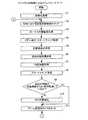
図19、図20は、本発明の第1の実施の形態におけるパチスロ機1の主制御回路71による制御処理を示すメインフローチャートである。メインフローチャートは、ROM32に記憶された制御プログラムにより実行される処理手順を示すものであり、CPU31によって実施される。 19 and 20 are main flowcharts showing the control processing by the
初めに、CPU31は、遊技開始時の初期化処理を行う(ステップS1)。具体的には、RAM33の記憶内容の初期化、通信データの初期化などを行う。 First, the
次いで、1ゲーム終了時用初期化処理、すなわち、ゲーム終了時のRAM33の所定の記憶領域の情報を消去する(ステップS2)。具体的には、前回のゲームに使用されたRAM33の書き込み可能エリアのデータの消去、RAM33の書き込みエリアへの次のゲームに必要なパラメータの書き込み、次のゲームのシーケンスプログラムの開始アドレスの指定などを行う。 Next, initialization processing for one game end, that is, information in a predetermined storage area of the
次に、CPU31は、ボーナス作動監視処理を行う(ステップS3)。ここでは、BB作動中であるときに、RBも作動中となるようにする。 Next, the
次に、メダル受付・スタートチェック処理を行う(ステップS4)。具体的には、リプレイ作動中フラグに基づく前回のゲームでリプレイが成立したか否かの判別情報、メダル投入口22へのメダル投入に基づく投入メダルセンサ22Sからの入力、および、BETスイッチ11、12、13からの入力、に応じて、RAM33にセットされた投入枚数カウンタを更新する。ここで、リプレイ作動中フラグは、リプレイの成立の有無を識別する情報であり、投入枚数カウンタは、次のゲームにおける投入枚数を特定する情報である。 Next, a medal acceptance / start check process is performed (step S4). Specifically, information for determining whether or not a replay has been established in the previous game based on the replay operating flag, an input from the inserted
また、投入枚数カウンタの値に応じて有効ラインの設定を行う。例えば、投入枚数カウンタが"3"であれば、全ての有効ライン上に表示された図柄の組合せに基づいて後述の表示役を決定する。さらに、メダルが投入されていること(例えば、投入枚数カウンタが"1"以上であること、または、投入枚数カウンタが最大値"3"であること)を条件として、スタートレバー6の操作に基づくスタートスイッチ6Sからの入力の有無をチェックする。 In addition, the effective line is set according to the value of the insertion number counter. For example, if the inserted number counter is “3”, a display combination to be described later is determined based on a combination of symbols displayed on all active lines. Further, based on the operation of the
続いて、CPU31は、内部抽籤用の乱数値抽出処理を行う(ステップS5)。この乱数値抽出処理では、サンプリング回路37を介して乱数発生器36により発生されている「0〜65535」の範囲の乱数値から1つの乱数値を抽出し、抽出した乱数値をRAM33の乱数値記憶領域に記憶する。 Subsequently, the
次いで、CPU31は、遊技状態監視処理を行う(ステップS6)。この遊技状態監視処理では、BB作動中フラグ、RB作動中フラグ、または持越役の情報に基づいて、今回のゲームにおける遊技状態を識別する情報をRAM33にセットする。 Next, the
次に、CPU31は、内部抽籤処理を行う(ステップS7)。 Next, the
この内部抽籤処理では、内部抽籤テーブル決定テーブルを参照し、前記遊技状態監視処理で取得した遊技状態に基づいて、抽籤回数と内部抽籤テーブルの種別を決定する。例えば、遊技状態が一般遊技状態である場合、抽籤回数として"7"を決定するとともに、内部抽籤テーブルとして一般遊技状態用内部抽籤テーブルを決定する。 In the internal lottery process, the internal lottery table determination table is referred to, and the number of lotteries and the type of the internal lottery table are determined based on the gaming state acquired in the gaming state monitoring process. For example, when the gaming state is the general gaming state, “7” is determined as the number of lotteries, and the internal lottery table for the general gaming state is determined as the internal lottery table.
次いで、この一般遊技状態用内部抽籤テーブルを参照し、前記乱数値抽出処理で取得した乱数値(RAM33の乱数値記憶領域に記憶された乱数値)に基づいて、今回の内部当籤役を決定する。次いで、決定した内部当籤役がボーナスであれば、このボーナスを持越役としてRAM33の持越役格納領域にセットする。さらに、前記で決定した今回の内部当籤役と持越役との論理和を当籤役として決定する。 Next, with reference to this internal gaming state internal lottery table, the current internal winning combination is determined based on the random number value acquired by the random value extraction process (the random value stored in the random value storage area of the RAM 33). . Next, if the determined internal winning combination is a bonus, this bonus is set as a carryover combination in the carryover combination storage area of the
例えば、内部当籤役として「ベルの小役」が決定され、持越役として「BB1」がセットされていれば、「ベルの小役」と「BB1」を当籤役として決定する。つまり、内部当籤役と持越役は、円盤停止時の図柄の表示態様の決定に関わる情報であり、これらを含めて「当籤役」という。 For example, if “Bell's small combination” is determined as the internal winning combination and “BB1” is set as the carryover combination, “Bell's small combination” and “BB1” are determined as the winning combinations. In other words, the internal winning combination and the carryover combination are information related to the determination of the display mode of the symbol when the disk is stopped, and are referred to as “winning combination”.
次いで、CPU31は、副制御回路72に対して「スタートコマンド」を送信する(ステップS8)。「スタートコマンド」には、内部当籤役、遊技状態、使用された内部抽籤テーブルの情報などが含まれている。 Next, the
続いて、前回のゲームが開始してから所定時間(例えば"4.1秒")経過しているか否か判断し(ステップS9)、この判断結果が"YES"のときにはタイマのセット処理(ステップS11)に移り、"NO"のときには待ち時間消化処理(ステップS10)に移る。 Subsequently, it is determined whether or not a predetermined time (for example, “4.1 seconds”) has elapsed since the start of the previous game (step S9). When the determination result is “YES”, a timer setting process (step The process proceeds to S11), and when “NO”, the process proceeds to a waiting time digestion process (step S10).
待ち時間消化処理(ステップS10)では、前回のゲームが開始してから所定時間経過するまでの間、以降の処理を行わずに、ゲーム開始待ち時間の消化(ウェイト)を行う。具体的には、前回のゲームが開始してから"4.1秒"経過するまでの間、遊技者のゲームを開始する操作に基づく入力を無効にする処理を行う。 In the waiting time digestion process (step S10), the game start waiting time is digested (wait) without performing the subsequent processes until the predetermined time has elapsed since the previous game started. Specifically, a process of invalidating the input based on the player's operation to start the game is performed until “4.1 seconds” have elapsed since the previous game started.
次に、ゲーム監視用タイマのセット処理(ステップS11)において、ゲーム監視用タイマをセットする。具体的には、1ゲーム間監視用タイマ、自動停止タイマをセットする。1ゲーム間監視用タイマは、前記ゲーム間の時間を確保するために、ゲームが開始してからの時間を測定するタイマであり、自動停止タイマは、遊技者の停止ボタン7L、7C、7Rの停止操作によらずに自動的に円盤301〜303を停止させるためのタイマである。 Next, in the game monitoring timer setting process (step S11), the game monitoring timer is set. Specifically, an intergame monitoring timer and an automatic stop timer are set. The inter-game monitoring timer is a timer for measuring the time from the start of the game in order to secure the time between the games, and the automatic stop timer is used for the player's
続いて、CPU31は、モータ駆動回路39に対して、全円盤(円盤301〜303)の回転開始要求を行い(ステップS12)、モータ駆動回路39は、全円盤の回転処理を行う。このとき、CPU31は、副制御回路72に対して「円盤回転開始コマンド」を送信する。 Subsequently, the
次いで、円盤停止制御処理を行う(ステップS13)。具体的には、いずれかの停止ボタン7L、7C、7Rが操作された場合、停止テーブルに基づいて、停止操作された停止ボタン7L、7C、7Rに対応する円盤301〜303を停止させる。このとき、副制御回路72に対して、「円盤停止コマンド」を送信する。「円盤停止コマンド」には、停止円盤、停止位置の情報などが含まれている。 Next, a disk stop control process is performed (step S13). Specifically, when any one of the
全ての停止ボタン7L、7C、7Rが操作され、全ての円盤301〜303を停止させたら、図柄組合せテーブルに基づいて、表示役と払出枚数を決定する(ステップS14)。この処理では、表示窓4の図柄の停止態様に基づいて表示役(当籤が成立した役)を識別し、表示役フラグをセットする。具体的には、有効ラインに沿って並ぶ図柄のコードナンバーおよび図柄組合せテーブル、投入枚数に基づいて、表示役と払出枚数を識別する。 When all the
次いで、副制御回路72に対して表示役コマンドを送信する(ステップS15)。「表示役コマンド」には、表示役を特定する表示役フラグの情報、払出枚数に関する情報などが含まれる。 Next, a display combination command is transmitted to the sub control circuit 72 (step S15). The “display combination command” includes information on a display combination flag for specifying a display combination, information on the number of payouts, and the like.
次に、メダル払出処理を行う(ステップS16)。このメダル払出処理では、クレジットモードであれば、払出枚数情報に基づいて、RAM33にセットされたクレジットカウンタを更新する。クレジット表示部19のクレジットカウンタの値は、このクレジットカウンタの更新に基づいて、表示させる。また、払出モードであれば、払出枚数情報に基づいて、ホッパー駆動回路41によりホッパー40を駆動制御してメダルの払出しを行う。また、CPU31は、表示役がリプレイであれば、リプレイ作動中フラグを"オン"にする。また、CPU31は、メダルの獲得枚数を更新する。この後、CPU31は、副制御回路72へ払出終了コマンドを送信する。この払出終了コマンドは、メダルの払出しが完了したことを示す情報を含む。 Next, a medal payout process is performed (step S16). In this medal payout process, in the credit mode, the credit counter set in the
次いで、CPU31は、前記払出枚数に基づいて、ボーナス終了枚数カウンタの値を更新する(ステップS17)。ここでは、ボーナス終了枚数カウンタの値が"1"以上であれば、メダルの払出枚数に応じて当該カウンタの値を減算する。 Next, the
次いで、CPU31は、RAM33の所定の記憶領域を参照して、BB作動中フラグおよびRB作動中フラグを確認して(ステップS18)、BB作動中フラグまたはRB作動中フラグが"オン"であれば、ボーナス終了チェック処理を行う(ステップS19)。 Next, the
BB作動中フラグおよびRB作動中フラグがともに"オフ"であるか(ステップS18で判定)、ボーナス終了チェック処理(ステップS19)が終了したら、ボーナス作動チェック処理を行う(ステップS20)。 If both the BB operating flag and the RB operating flag are “off” (determined in step S18), the bonus operation check process is performed (step S20) when the bonus end check process (step S19) ends.
ボーナス作動チェック処理(ステップS20)が終了したら、1ゲーム終了用初期化処理(図19のステップS2)に戻る。 When the bonus operation check process (step S20) ends, the process returns to the one-game end initialization process (step S2 in FIG. 19).
図21は、本発明の第1の実施の形態における主制御回路71のCPU31による定期割込処理を示すフローチャートである。この定期割込処理は、1.1173msごとに主制御回路71で定期的に行われる。 FIG. 21 is a flowchart showing a periodic interrupt process performed by the
初めに、CPU31は、デモ用タイマにセットされた値を"1"減算するためのタイマ更新処理を行う(ステップS201)。デモ用タイマは、遊技者による操作(BET操作など)が行われない状態(非遊技状態)が所定時間(例えば、約45秒)継続したことを計測するためのタイマである。例えば、メダル受付・スタートチェック処理の開始時に、デモ用タイマに「40000」をセットし、遊技者による操作(BET操作など)が行われない状態(非遊技状態)でデモ用タイマが「0」となったときに、CPU31は、BETランプ9a〜9cが点灯している場合には、BETランプ9a〜9cを消灯し、デモコマンドを副制御回路72に送信する。なお、デモコマンドを受信した副制御回路72は、いわゆるデモ画像を液晶表示画面5aに表示する。 First, the
次いで、CPU31は、入力ポートチェック処理を行う(ステップS202)。この入力ポートチェック処理では、メダル投入口22からメダルが投入されたことにより投入メダルセンサ22Sによるメダル投入の検知、スタートレバー6の傾動操作によるスタートスイッチ6Sからの入力の有無等の入力操作を確認する。 Next, the
次いで、CPU31は、円盤回転駆動処理を行う(ステップS203)。具体的には、制御対象の円盤(第1円盤301、第2円盤302、第3円盤303のいずれか)を示す情報を円盤識別子(例えば、左"0"、中"1"、右"2"として識別する)として設定し、モータ駆動回路39に指令して当該円盤の駆動を制御する。 Next, the
次いで、CPU31は、ランプ類、LED類を駆動するランプ・7SEG駆動処理を行い(ステップS204)、定期割込処理を終了する。このランプ・7SEG駆動処理において、CPU31は、例えば、貯留(クレジット)されているメダルの枚数、入賞時のメダルの払出枚数などをクレジット表示部19、払出表示部18に表示させるコマンドをRAM33の所定の記憶領域に書き込む。また、CPU31は、BETされているメダルの数に応じてBETランプ9a〜9cを点灯させるコマンド、キャビネット2の前面に設けられたWINランプ17などを点灯させるコマンドをRAM33の所定の記憶領域に書き込む。これらのコマンドは、副制御回路72に送信されることとなる。 Next, the
図22は、本発明の第1の実施の形態における副制御回路72の画像制御CPU82によるリセット割込処理を示すフローチャートである。 FIG. 22 is a flowchart showing reset interrupt processing by the
図22に示すように、副制御回路72において行われるリセット割込処理では、初めに、画像制御CPU82は、主制御回路71から入力されたコマンドを受信するためのコマンド受信処理を行う(ステップS301)。コマンド受信処理では、主制御回路71から受信したコマンドに応じて、各遊技情報を更新し、受信したコマンドに応じて、演出を決定する処理を行う。 As shown in FIG. 22, in the reset interrupt process performed in the
例えば、主制御回路71からスタートコマンドを受信することを契機として、スタートコマンドの情報を取得し、ボーナスに当籤したか否か判別する。ここで、ボーナスに当籤したものと判別した場合には、演出識別子を決定するための乱数値を取得して演出識別子決定処理を行う。演出識別子決定処理では、前記取得した乱数値に基づいて演出識別子として「図柄液晶表示演出」を決定するか否かの抽籤を行う。なお、図柄液晶表示演出は、第1円盤301の図柄領域301bに配される図柄と重なるように、図柄領域301bに配される図柄と同じ図柄が、液晶表示装置5により第1円盤301の回転方向と同じ方向に移動表示されるものである(図24参照)。 For example, when receiving a start command from the
次いで、決定した演出にしたがって、ランプ(BETランプ9a〜9c、WINランプ17)類に制御信号を送信するランプ演出リクエスト処理、スピーカ21L、21R等に制御信号を送信するサウンド演出リクエスト処理、液晶表示装置5等に制御信号を送信する液晶演出リクエスト処理を行って、コマンド受信処理を終了する。 Next, according to the determined effects, lamp effect request processing for transmitting control signals to lamps (
次いで、画像制御CPU82は、画像制御IC88、音・ランプ制御回路73以外へのコマンドを出力するためのコマンド出力処理を行う(ステップS302)。 Next, the
次いで、画像制御CPU82は、画像描画処理を行い(ステップS303)、リセット割込処理を終了する。画像描画処理では、決定された演出データに基づいて画像表示する演出画像の描画を行う。なお、画像描画処理では、画像制御CPU82は、画像制御IC88の制御RAM89への画像データの書き込みおよびビデオRAM87に設けたフレームバッファヘの画像データの書き込みを行う。フレームバッファに書き込まれた画像データは、液晶表示装置5に転送され、当該画像データに対応する画像が液晶表示画面5aに(1/30s間)表示される。 Next, the
図23は、本発明の第1の実施の形態における副制御回路の画像制御CPUによる画像描画処理を示すフローチャートであって、図22のステップS303の詳細を示すものである。 FIG. 23 is a flowchart showing image drawing processing by the image control CPU of the sub control circuit according to the first embodiment of the present invention, and shows details of step S303 in FIG.
図23に示すように、画像描画処理では、まず、画像制御CPU82は、演出識別子として「図柄液晶表示演出」が決定されたか否かを判別する(ステップS311)。ステップS311の判別が"YES"である場合、画像制御CPU82は、演出識別子「図柄液晶表示演出」に係る演出内容を決定し、画像制御IC88は、その演出内容に応じた画像を表示画面5aの所定領域(表示領域に相当する)に描画する(ステップS312)。 As shown in FIG. 23, in the image drawing process, first, the
一方、ステップS311の判別が"NO"である場合、画像制御CPU82は、演出識別子「図柄液晶表示演出」を除いた他の演出内容を決定し、画像制御IC88は、その演出内容に応じた画像を表示画面5aの所定領域に描画する(ステップS313)。 On the other hand, if the determination in step S311 is “NO”, the
図24は、本発明の第1の実施の形態における図柄液晶表示演出を示す図である。 FIG. 24 is a diagram showing a design liquid crystal display effect in the first embodiment of the present invention.
図柄液晶表示演出においては、第1円盤301の図柄領域301bに配される図柄と重なるように、図柄領域301bに配される図柄と同じ図柄が、液晶表示装置5により第1円盤301の回転方向と同じ方向に移動表示される。図24に示す例では、表示窓4に対して第1円盤301の回転方向と逆方向に位置する3コマ分の領域において、"ベル"、"スイカ"、"リプレイ"の図柄が液晶表示画面5aに表示されている。そして、液晶表示画面5aに表示されている図柄は、第1円盤301の回転に伴って移動する。なお、図24に示す例では、前記3コマ分の領域において図柄が移動表示されるものとする。 In the design liquid crystal display effect, the same symbol as the symbol arranged in the
図柄液晶表示演出において、表示窓4以外の部分で遊技者が第1円盤301の図柄領域301bに配される図柄を認識することができるため、目押しの不得手な遊技者でも容易に目押しを行うことができるようになる。 In the design liquid crystal display effect, since the player can recognize the symbols arranged in the
このような本発明の第1の実施の形態のパチスロ機1によれば、第1円盤301と第2円盤302と第3円盤303とが重なり、第1円盤301の図柄領域301bと第2円盤302の図柄領域302bと第3円盤303の図柄領域303bとに配された遊技用の複数の図柄の一部を変動表示するため、筐体の前後方向の厚さを遊技用の複数の図柄が配される回胴装置の直径以上にすることが不要となる。したがって、筐体の前後方向の厚さを削減することができる。 According to the
また、パチスロ機1前面側から順に第1円盤301、第2円盤302、第3円盤303が配設され、遊技用の複数の図柄が配された第2円盤302の図柄領域302bと透明に形成された第1円盤301の透過領域301c1とが重なり、遊技用の複数の図柄が配された第3円盤303の図柄領域303bと透明に形成された第1円盤301の透過領域301c2および第2円盤302の透過領域302cとが重なるため、第1円盤301、第2円盤302、第3円盤303のそれぞれに配された遊技用の複数の図柄を遊技者が視認することができる。In addition, a
また、第1円盤301と第2円盤302と第3円盤303とを同一の直径にすることができるため、3つの円盤301〜303の負荷を均等にすることができる。したがって、3つの円盤301〜303を回転駆動するためのメインステッピングモータ491〜493を同一仕様のものにすることができ、その回転駆動の制御も同一にすることができる。 Moreover, since the
さらに、表示窓4以外の部分で遊技者が第1円盤301の図柄領域301bに配される図柄を認識することができるため、目押しの不得手な遊技者でも容易に目押しを行うことができる。 Furthermore, since the player can recognize the symbols arranged in the
なお、本実施の形態では、第1円盤301の図柄領域301b、第2円盤302の図柄領域302b、第3円盤303の図柄領域303bに配された遊技用の複数の図柄の大きさは同じとしているが、これに限られない。例えば、図柄領域301bに配される図柄を図柄領域302bに配される図柄よりも大きくし、図柄領域302bに配される図柄を図柄領域303bに配される図柄よりも大きくする。本実施の形態では、図柄領域301bに配された1つの図柄に割り当てることが可能な領域が、図柄領域302bに配された1つの図柄に割り当てることが可能な領域よりも広く、図柄領域302bに配された1つの図柄に割り当てることが可能な領域が、図柄領域303bに配された1つの図柄に割り当てることが可能な領域よりも広いため、上述のようにすることができる。 In the present embodiment, it is assumed that the size of a plurality of symbols for gaming arranged in the
これにより、図柄領域301b、302b、303bで目押しのし易さを変化させることができるため、遊技の興趣を向上させることができる。 This makes it possible to change the ease of pressing in the
また、本実施の形態では、第1円盤301の図柄領域301bに配された図柄と同じ図柄を液晶表示装置5に表示させているが、これに限られず、第1円盤301の図柄領域301bに加えて第2円盤302の図柄領域302bおよび第3円盤303の図柄領域303bに配される図柄と同じ図柄を液晶表示装置5に表示させてもよい。これにより、第2円盤302および第3円盤303についても、遊技者が目押しを容易に行うことができる。 In the present embodiment, the same symbol as the symbol arranged in the
(第2の実施の形態)
図25は、本発明の第2の実施の形態における円盤機構部の構成を示す断面図である。なお、第2の実施の形態のパチスロ機1は、第1の実施の形態のパチスロ機1と円盤機構部において異なっているが、他の構成は同様に構成されている。したがって、同一の構成についてはその説明を省略し、特に相違点についてのみ詳述する。また、第2の実施の形態の円盤501、502、503は、それぞれ第1の実施の形態の円盤301、302、303に対応する。(Second Embodiment)
FIG. 25 is a cross-sectional view showing a configuration of a disk mechanism unit in the second embodiment of the present invention. The
図25に示すように、3つの円盤501〜503は、透明材料からなる板状の支持部材304〜306に支持されたメインステッピングモータ491〜493の回転軸491a、492a、493aに取り付けられている。回転軸491a、492a、493aは、液晶表示画面5aに対して垂直に配置され、円盤501〜503の盤面は、液晶表示画面5aに対して平行となっている。また、3つの円盤501〜503の外径は同一であって、3つの回転軸491a、492a、493aの軸線は一致している。なお、前記外径は「2(R1+R2+R3+R4)」であり、「R1=R2=R3」となっている。ここでは、3つの円盤501〜503の負荷(例えば、重量、厚さ、外径)を均等とし、同一仕様のメインステッピングモータ491〜493を同一の制御で駆動させている。また、3つの円盤501〜503は、液晶表示画面5aから筐体の奥へ向けて第3円盤503、第2円盤502、第1円盤501の順に重ねて設けられている。したがって、筐体の円盤機構部の厚さは、メインステッピングモータ491〜493の仕様と円盤501〜503および支持部材304〜306の厚さによって規定されることになる。As shown in FIG. 25, the three
第1円盤501は、回転軸491aを中心とした円形の非透過領域501a(501a1、501a2、501a3に相当する)と、非透過領域501aの周縁の環形の図柄領域501bと、を有し、透過領域を有していない(図30参照)。ここで、非透過領域501aの径は「2(R2+R3+R4)」であり、図柄領域501bの幅は「R1」である。The
第2円盤502は、回転軸492aを中心とした円形の非透過領域502a(502a1、502a2に相当する)と、非透過領域502aの周縁の環形の図柄領域502bと、図柄領域502bの周縁の環形の透過領域502cと、を有している(図29参照)。ここで、非透過領域502aの径は「2(R3+R4)」であり、図柄領域502bの幅は「R2」であり、透過領域502cの幅は「R1」である。The
第3円盤503は、回転軸493aを中心とした円形の非透過領域503aと、非透過領域503aの周縁の環形の図柄領域503bと、図柄領域503bの周縁の環形の透過領域503c(503c1、503c2に相当する)と、を有している(図28参照)。ここで、非透過領域503aの径は「2R4」であり、図柄領域503bの幅は「R3」であり、透過領域503cの幅は「R1+R2」である。The
なお、非透過領域501a、502a、503aは、例えば、不透明な樹脂材料で形成されるか、あるいは透明または半透明の樹脂材料で形成された後に着色されたものである。また、図柄領域501b、502b、503bは、例えば、透明または半透明の樹脂材料で形成されたものである。図柄領域501b、502b、503bの表面(液晶表示画面5aに対向する面)には、全周にわたって後述する21個の図柄(図27参照)が等間隔で配置されている。また、透過領域502c、503cは、透明または半透明の樹脂材料で形成されたものである。また、3つの円盤501〜503は同一材料で一体形成しても良い。あるいは異なる材料で形成しても良い。 The
そして、図柄領域の外径は、第3円盤503の図柄領域503b、第2円盤502の図柄領域502b、第1円盤501の図柄領域501bの順に大きくなっている。また、3つの図柄領域501b、502b、503bの幅は同一(R1=R2=R3)となっている。第1円盤501の図柄領域501bと液晶表示画面5aの間には、同一幅の第2円盤502の透過領域502cおよび第3円盤503の透過領域503c1が介在し、第2円盤502の図柄領域502bと液晶表示画面5aの間には、同一幅の第3円盤503の透過領域503c2が介在しているため、液晶表示画面5a上の表示窓4には、第3円盤503の透過領域503cを介して第2円盤502の図柄領域502bおよび第1円盤501の図柄領域501bが透過表示されるとともに、第3円盤503の図柄領域503bが透過表示されることになる。The outer diameter of the symbol area increases in the order of the
また、3つの円盤501〜503の回転位置(図柄位置)を検出するため、3つの支持部材304〜306におけるメインステッピングモータ491〜493の取り付け面には、例えば、発光部と受光部を備えた反射式のフォトセンサ50a、50b、50cが設けられている。一方、3つの円盤501〜503の非透過領域501a、502a、503aの裏面(前記取り付け面との対向面)には、円盤の回転に応じて前記受光部を遮る位置にスタートインデックスとしての遮蔽片50d、50e、50fが設けられている。フォトセンサ50a、50b、50cは、円盤501〜503の回転にしたがって遮蔽片50d、50e、50fの通過を検出し、パルス信号を発生するようになっている。このパルス信号を基準として、メインステッピングモータ491〜493の駆動パルス数を計数することにより、計数結果に基づいて遮蔽片50d、50e、50fからの変位を検出することができる。 In addition, in order to detect the rotational positions (symbol positions) of the three
図26は、本発明の第2の実施の形態における液晶表示画面5aに表示された表示窓4を示す図である。 FIG. 26 is a diagram showing the
図26に示すように、液晶表示画面5aにおいて、表示窓4に相当する領域のみ光を透過させることにより、円盤501〜503の図柄領域501b、502b、503bの一部を透視可能としている。表示窓4は、図柄領域501b、502b、503bに配された図柄の3コマ分が透過表示されるよう、略扇形としている。また、表示窓4には、賭け数に応じて前述の有効ライン8a〜8eが表示されるようになっている。有効ラインのうち、水平方向にセンターライン8cが表示され、斜め方向にはトップライン8b、ボトムライン8d、クロスダウンライン8a、クロスアップライン8eが表示される。本実施の形態では、環形の図柄領域501b、502b、503bの左側の一部が表示窓4と重なるよう、表示窓4を透過表示するとともに有効ライン8a〜8eを表示している。また、表示窓4に表示される図柄の上下方向が揃うよう、図柄領域501b、502b、503bの図柄を配列している。表示窓4においては、3つの円盤501〜503の回転に伴い、3つの図柄列が略上下方向に変動するため、3つのリールの図柄列を変動させるパチスロ機に慣れた遊技者も違和感なく遊技を行うことができる。 As shown in FIG. 26, in the liquid
図27は、本発明の第2の実施の形態における3つの円盤501〜503の図柄領域501b、502b、503bを示す図である。図28は、本発明の第2の実施の形態における第3円盤503を示す図である。図29は、本発明の第2の実施の形態における第2円盤502を示す図である。図30は、本発明の第2の実施の形態における第1円盤501を示す図である。 FIG. 27 is a diagram
本実施の形態では、前述のように操作方向(図25参照)の手前から第3円盤503、第2円盤502、第1円盤501の順に3つの円盤が重なり、図柄領域503b、図柄領域502b、図柄領域501bの順に外径が大きくなるため、図27に示すように、3つの図柄領域501b、502b、503bが同心のリングとして円盤の中心(回転軸491a、492a、493aに相当する)から径方向に広がることになる。なお、3つの図柄領域501b、502b、503bの図柄同士が重なることはない。 In the present embodiment, as described above, three disks overlap in the order of the
また、図28〜図30に示すように、第1円盤501の図柄領域501b、第2円盤502の図柄領域502b、第3円盤503の図柄領域503bには、全周にわたって複数種類の図柄が21個配列された図柄列が形成されている。各図柄には"00"〜"20"のコードナンバーが付され、ROM32(図17参照)に格納(記憶)されている。 In addition, as shown in FIGS. 28 to 30, the
3つの図柄領域501b、502b、503bのそれぞれには、"赤7"、"BAR"、"リプレイ"、"チェリー"、"プラム"、"ベル"および"スイカ"の図柄で構成される図柄列が表わされている。3つの円盤501〜503は、図柄領域501b、502b、503bが図中矢印方向に移動するように回転駆動される。 In each of the three
前記図柄列は、例えば、印刷加工によって図柄領域501b、502b、503bに形成されている。ここで、図柄領域501b、502b、503bは、円盤501〜503の回転軸に対して垂直に配されているため、印刷加工された前記図柄列が遠心力によって剥離することを回避し、パチスロ機1の耐久性を向上させることになる。なお、通常の円筒状のリール機構を用いた場合には、図柄列が印刷された短冊状のシート部材をリールの外周に装着する(例えば、貼着する)ことになるため、リールの回転による遠心力によって前記シート部材の端部継ぎ目部分がリールから剥離することがありうる。 The symbol row is formed in the
このような本発明の第2の実施の形態のパチスロ機1によれば、第1円盤501と第2円盤502と第3円盤503とが重なり、第1円盤501の図柄領域501bと第2円盤502の図柄領域502bと第3円盤503の図柄領域503bとに配された遊技用の複数の図柄の一部を変動表示するため、筐体の前後方向の厚さを遊技用の複数の図柄が配される回胴装置の直径以上にすることが不要となる。したがって、筐体の前後方向の厚さを削減することができる。 According to the
また、パチスロ機1前面側から順に第3円盤503、第2円盤502、第1円盤501が配設されているため、遊技用の複数の図柄が配された第1円盤501の図柄領域501bと第2円盤502の非透過領域502a、図柄領域502bおよび第3円盤503の非透過領域503a、図柄領域503bとが重ならず、遊技用の複数の図柄が配された第2円盤502の図柄領域502bと第3円盤503の非透過領域503a、図柄領域503bとが重ならない。したがって、第1円盤501、第2円盤502、第3円盤503のそれぞれに配された遊技用の複数の図柄を遊技者が視認することができる。 In addition, since the
さらに、第1円盤501と第2円盤502と第3円盤503とを同一の直径にすることができるため、3つの円盤501〜503の負荷を均等にすることができる。したがって、3つの円盤501〜503を回転駆動するためのメインステッピングモータ491〜493を同一仕様のものにすることができ、その回転駆動の制御も同一にすることができる。 Furthermore, since the
1 パチスロ機
4 表示窓
6 スタートレバー
7L、7C、7R 停止ボタン
30 マイクロコンピュータ
31 CPU
32 ROM
33 RAM
50a、50b、50c フォトセンサ(円盤回転センサ)
50d、50e、50f 遮蔽片
71 主制御回路
72 副制御回路
301、302、303 円盤
301a、302a、303a 非透過領域
301b、302b、303b 図柄領域
301c、302c 透過領域
304、305、306 支持部材
491、492、493 メインステッピングモータ
491a、492a、493a 回転軸
501、502、503 円盤
501a、502a、503a 非透過領域
501b、502b、503b 図柄領域
502c、503c 透過領域1 Pachi-
32 ROM
33 RAM
50a, 50b, 50c Photo sensor (disk rotation sensor)
50d, 50e,
Claims (2)
Translated fromJapanese前記開始操作検出手段により行われる開始操作の検出に基づいて内部当籤役を決定する内部当籤役決定手段と、
回転軸を中心として回転し、第1の径と前記第1の径よりも小さい第2の径との間の第1の環状領域と、前記第2の径と前記第2の径よりも小さい第3の径との間の第2の環状領域と、前記第3の径と前記第3の径よりも小さい第4の径との間の第3の環状領域と、を有し、前記第1の環状領域に遊技用の複数の図柄が配された第1の円盤と、
前記第1の円盤と所定の距離をもって配設される円盤であって、前記回転軸を中心として回転し、前記第2の径と前記第3の径との間の第4の環状領域と、前記第3の径と前記第4の径との間の第5の環状領域と、を有し、前記第4の環状領域に遊技用の複数の図柄が配された第2の円盤と、
前記第2の円盤と所定の距離をもって配設される円盤であって、前記回転軸を中心として回転し、前記第3の径と前記第4の径との間の第6の環状領域を有し、前記第6の環状領域に遊技用の複数の図柄が配された第3の円盤と、
前記第1の環状領域と前記第4の環状領域と前記第6の環状領域とに配された遊技用の複数の図柄の一部を変動表示し、前記複数の図柄の停止表示によって所定の入賞態様を表示する図柄表示手段と、
前記開始操作検出手段により行われる開始操作の検出に基づいて前記第1の円盤と前記第2の円盤と前記第3の円盤により列表示される遊技用の図柄の変動を行う図柄変動手段と、
前記第1の円盤と前記第2の円盤と前記第3の円盤により列表示される遊技用の図柄の変動の停止操作の検出を行う停止操作検出手段と、
前記停止操作検出手段により行われる停止操作の検出と前記内部当籤役決定手段により決定される内部当籤役とに基づいて、該当する円盤により列表示される遊技用の図柄の変動の停止制御を行う停止制御手段と、
前記停止制御手段により行われる停止制御に基づいて前記図柄表示手段に所定の入賞態様が停止表示された場合に、遊技者に遊技価値を付与する遊技価値付与手段と、を備え、
前記第2の環状領域と前記第3の環状領域と前記第5の環状領域とは透明に形成され、
遊技機前面側から順に前記第1の円盤、前記第2の円盤、前記第3の円盤が配設されることを特徴とする遊技機。Start operation detecting means for detecting a start operation of the game;
An internal winning combination determining means for determining an internal winning combination based on detection of a start operation performed by the start operation detecting means;
A first annular region that rotates about a rotation axis and is between a first diameter and a second diameter that is smaller than the first diameter, and is smaller than the second diameter and the second diameter A second annular region between a third diameter and a third annular region between the third diameter and a fourth diameter smaller than the third diameter, and A first disk in which a plurality of gaming symbols are arranged in one annular region;
A disk disposed at a predetermined distance from the first disk, rotating about the rotation axis, and a fourth annular region between the second diameter and the third diameter; A second circular disk having a fifth annular region between the third diameter and the fourth diameter, wherein a plurality of gaming symbols are arranged in the fourth annular region;
A disk disposed at a predetermined distance from the second disk, wherein the disk rotates about the rotation axis and has a sixth annular region between the third diameter and the fourth diameter; A third disk having a plurality of gaming symbols arranged in the sixth annular region;
A part of a plurality of gaming symbols arranged in the first annular region, the fourth annular region, and the sixth annular region are variably displayed, and a predetermined winning is achieved by the stop display of the plurality of symbols. A symbol display means for displaying an aspect;
Symbol variation means for varying the symbols for games displayed in a row by the first disk, the second disk, and the third disk based on detection of the start operation performed by the start operation detection unit;
A stop operation detecting means for detecting a stop operation of a variation of the game symbols displayed in a row by the first disk, the second disk, and the third disk;
Based on the detection of the stop operation performed by the stop operation detecting means and the internal winning combination determined by the internal winning combination determining means, stop control of variation of the game symbols displayed in a row by the corresponding disk is performed. Stop control means;
Game value giving means for giving a game value to a player when a predetermined winning mode is stopped and displayed on the symbol display means based on the stop control performed by the stop control means,
The second annular region, the third annular region, and the fifth annular region are formed to be transparent,
A gaming machine, wherein the first disk, the second disk, and the third disk are arranged in order from the front side of the gaming machine.
前記第3の円盤は、前記第1の径と前記第3の径との間の第8の環状領域を有していることを特徴とする請求項1に記載の遊技機。The second disk has a seventh annular region between the first diameter and the second diameter;
The gaming machine according to claim 1, wherein the third disk has an eighth annular region between the first diameter and the third diameter.
Priority Applications (1)
| Application Number | Priority Date | Filing Date | Title |
|---|---|---|---|
| JP2007140663AJP2008289792A (en) | 2007-05-28 | 2007-05-28 | Game machine |
Applications Claiming Priority (1)
| Application Number | Priority Date | Filing Date | Title |
|---|---|---|---|
| JP2007140663AJP2008289792A (en) | 2007-05-28 | 2007-05-28 | Game machine |
Publications (1)
| Publication Number | Publication Date |
|---|---|
| JP2008289792Atrue JP2008289792A (en) | 2008-12-04 |
Family
ID=40165147
Family Applications (1)
| Application Number | Title | Priority Date | Filing Date |
|---|---|---|---|
| JP2007140663APendingJP2008289792A (en) | 2007-05-28 | 2007-05-28 | Game machine |
Country Status (1)
| Country | Link |
|---|---|
| JP (1) | JP2008289792A (en) |
Cited By (1)
| Publication number | Priority date | Publication date | Assignee | Title |
|---|---|---|---|---|
| US9022849B2 (en) | 2010-07-01 | 2015-05-05 | Aristocrat Technologies Australia Pty Limited | Method of gaming, a gaming system, and a game controller |
- 2007
- 2007-05-28JPJP2007140663Apatent/JP2008289792A/enactivePending
Cited By (1)
| Publication number | Priority date | Publication date | Assignee | Title |
|---|---|---|---|---|
| US9022849B2 (en) | 2010-07-01 | 2015-05-05 | Aristocrat Technologies Australia Pty Limited | Method of gaming, a gaming system, and a game controller |
Similar Documents
| Publication | Publication Date | Title |
|---|---|---|
| JP2005296355A (en) | Game machine | |
| JP2007295965A (en) | Game machine | |
| JP2008188052A (en) | Game machine | |
| JP2008289793A (en) | Game machine | |
| JP2008289792A (en) | Game machine | |
| JP2006175099A (en) | Game machine | |
| JP4818745B2 (en) | Game machine | |
| JP2008272216A (en) | Game machine | |
| JP2008289714A (en) | Game machine | |
| JP2007029474A (en) | Game machine | |
| JP2008272218A (en) | Game machine | |
| JP2008006060A (en) | Game machine | |
| JP2007295969A (en) | Game machine | |
| JP2008125730A (en) | Game machine | |
| JP2007175362A (en) | Game machine | |
| JP2008183346A (en) | Game machine | |
| JP5117831B2 (en) | Game machine | |
| JP5426736B2 (en) | Game machine | |
| JP2008272217A (en) | Game machine | |
| JP2006122162A (en) | Game machine | |
| JP2006061264A (en) | Game machine | |
| JP2008289713A (en) | Game machine | |
| JP2007252656A (en) | Game machine and control method thereof | |
| JP2007029469A (en) | Game machine | |
| JP2008006062A (en) | Game machine |