JP2008286149A - Control device for internal combustion engine - Google Patents
Control device for internal combustion engineDownload PDFInfo
- Publication number
- JP2008286149A JP2008286149AJP2007133706AJP2007133706AJP2008286149AJP 2008286149 AJP2008286149 AJP 2008286149AJP 2007133706 AJP2007133706 AJP 2007133706AJP 2007133706 AJP2007133706 AJP 2007133706AJP 2008286149 AJP2008286149 AJP 2008286149A
- Authority
- JP
- Japan
- Prior art keywords
- air
- intake
- flow rate
- internal combustion
- combustion engine
- Prior art date
- Legal status (The legal status is an assumption and is not a legal conclusion. Google has not performed a legal analysis and makes no representation as to the accuracy of the status listed.)
- Pending
Links
Images


Classifications
- Y—GENERAL TAGGING OF NEW TECHNOLOGICAL DEVELOPMENTS; GENERAL TAGGING OF CROSS-SECTIONAL TECHNOLOGIES SPANNING OVER SEVERAL SECTIONS OF THE IPC; TECHNICAL SUBJECTS COVERED BY FORMER USPC CROSS-REFERENCE ART COLLECTIONS [XRACs] AND DIGESTS
- Y02—TECHNOLOGIES OR APPLICATIONS FOR MITIGATION OR ADAPTATION AGAINST CLIMATE CHANGE
- Y02T—CLIMATE CHANGE MITIGATION TECHNOLOGIES RELATED TO TRANSPORTATION
- Y02T10/00—Road transport of goods or passengers
- Y02T10/10—Internal combustion engine [ICE] based vehicles
- Y02T10/12—Improving ICE efficiencies
Landscapes
- Output Control And Ontrol Of Special Type Engine (AREA)
- Electrical Control Of Air Or Fuel Supplied To Internal-Combustion Engine (AREA)
- Combined Controls Of Internal Combustion Engines (AREA)
Abstract
Description
Translated fromJapanese本発明は、例えば、スロットル弁と、可変動弁機構によって開閉される吸気弁とによって各気筒に対する空気の吸気量が調節される内燃機関を制御するための内燃機関の制御装置であって、アイドリング状態において運転者によるアクセルの踏み込みに対する車両の加速応答性を高めることができるエンジン等の内燃機関を制御するための内燃機関の制御装置の技術分野に関する。 The present invention relates to an internal combustion engine control apparatus for controlling an internal combustion engine in which the amount of air intake to each cylinder is adjusted by, for example, a throttle valve and an intake valve that is opened and closed by a variable valve mechanism. The present invention relates to a technical field of a control device for an internal combustion engine for controlling an internal combustion engine such as an engine that can improve acceleration response of a vehicle with respect to depression of an accelerator by a driver in a state.
この種の内燃機関の制御装置は、可変動弁機構によってその開閉が制御される吸気弁と、運転者がアクセルを踏み込んだ際のアクセル開度に応じて開閉されるスロットル弁とを有している。内燃機関が備える気筒に吸入される吸気量は、スロットル弁の開度と、吸気弁の作用角及びリフト量とによって調節される。このような内燃機関の制御装置は、アクセルの踏み込みに応じて内燃機関に要求される要求トルクを出力可能なように、当該要求トルクに応じた吸気圧で所定量の空気を気筒に供給する技術(例えば、特許文献1参照。)、或いは、スロットル弁と共に可変動弁機構によって吸気量を制御する技術(例えば、特許文献2参照。)が提案されている。 A control device for this type of internal combustion engine has an intake valve whose opening and closing is controlled by a variable valve mechanism, and a throttle valve that is opened and closed according to the accelerator opening when the driver steps on the accelerator. Yes. The amount of intake air taken into a cylinder included in the internal combustion engine is adjusted by the opening of the throttle valve, the operating angle of the intake valve, and the lift amount. Such a control device for an internal combustion engine is a technique for supplying a predetermined amount of air to a cylinder with an intake pressure corresponding to the required torque so that the required torque required for the internal combustion engine can be output in response to depression of the accelerator. (For example, refer patent document 1.) Or the technique (for example, refer patent document 2) which controls intake air quantity with a variable valve mechanism with a throttle valve is proposed.
また、この種の内燃機関の制御装置では、複数の気筒相互においてリフト量のばらつきが高リフト量領域に比べて低リフト量領域で相対的に大きくなり、吸気弁のみによって吸気量を調節した場合には、各気筒間相互において吸気量にばらつきが生じてしまう。したがって、低リフト量領域では、スロットル弁の開度に応じて吸気量が調節される。 Also, in this type of internal combustion engine control device, the variation in lift amount among a plurality of cylinders is relatively larger in the low lift amount region than in the high lift amount region, and the intake amount is adjusted only by the intake valve. In other words, the intake air amount varies among the cylinders. Therefore, in the low lift amount region, the intake air amount is adjusted according to the opening of the throttle valve.
しかしながら、低リフト量領域では、気筒に空気を供給する吸気通路部のうちスロットル弁から気筒までの間を占める通路部分内における圧力が低く、例えば、アイドリング状態等のように各気筒に供給される吸気量が少ない状態から車両を加速させる場合、アクセルの踏み込み量に対する加速応答性が低くなってしまう技術的問題点がある。 However, in the low lift amount region, the pressure in the passage portion that occupies the space from the throttle valve to the cylinder in the intake passage portion that supplies air to the cylinder is low, and is supplied to each cylinder as in an idling state, for example. When accelerating the vehicle from a state where the intake air amount is small, there is a technical problem that the acceleration response to the accelerator depression amount is lowered.
よって、本発明は上記問題点等に鑑みてなされたものであり、例えば、車両を加速させる際の加速応答性を高めることができる内燃機関の制御装置を提供することを課題とする。 Therefore, the present invention has been made in view of the above-described problems, and an object of the present invention is to provide a control device for an internal combustion engine that can improve acceleration response when the vehicle is accelerated, for example.
本発明の第1の発明に係る内燃機関の制御装置は上記課題を解決するために、気筒に空気を供給するための吸気通路部の途中に設けられたスロットル弁と、前記気筒に供給される空気の吸気量を調節可能な吸気弁を開閉する可変動弁機構とを備え、且つ車両に搭載された内燃機関を制御するための内燃機関の制御装置であって、前記吸気通路部のうち前記スロットル弁の上流側に位置する第1通路部分、及び前記吸気通路部のうち前記スロットル弁の下流側に位置する第2通路部分を相互に繋ぐエアーバイパスと、前記エアーバイパスを流れる空気の流量を調節可能な流量調節手段と、前記スロットル弁によって前記吸気量が調節されている状態において、前記内燃機関に要求された要求トルクに応じて前記スロットル弁が開く際に、前記第2通路部分内の圧力が高まるように前記流量調節手段を制御する制御手段とを備える。 In order to solve the above problems, a control device for an internal combustion engine according to a first aspect of the present invention is supplied to a throttle valve provided in the middle of an intake passage for supplying air to the cylinder, and to the cylinder. An internal combustion engine control device for controlling an internal combustion engine mounted on a vehicle, comprising: a variable valve mechanism that opens and closes an intake valve capable of adjusting an air intake amount; An air bypass connecting the first passage portion located upstream of the throttle valve and the second passage portion located downstream of the throttle valve in the intake passage portion, and the flow rate of air flowing through the air bypass When the throttle valve is opened according to the required torque required for the internal combustion engine in a state where the intake air amount is adjusted by the adjustable flow rate adjusting means and the throttle valve, And a control means for controlling the flow rate adjusting means so that the pressure in passage portion is increased.
本発明の第1の発明に係る内燃機関の制御装置によれば、エアーバイパスは、吸気通路部のうちスロットル弁の上流側に位置する第1通路部分、及び吸気通路部のうちスロットル弁の下流側に位置する第2通路部分を相互に繋いでいる。即ち、エアーバイパスは、第1通路部分に空気を第2通路部分に供給可能になるように第1通路部分及び第2通路部分を相互に接続している。 According to the control apparatus for an internal combustion engine according to the first aspect of the present invention, the air bypass includes a first passage portion located upstream of the throttle valve in the intake passage portion and a downstream portion of the throttle valve in the intake passage portion. The second passage portions located on the side are connected to each other. In other words, the air bypass connects the first passage portion and the second passage portion to each other so that air can be supplied to the first passage portion.
流量調節手段は、前記エアーバイパスを流れる空気の流量を調節可能に構成されている。したがって、本発明の第1の発明に係る内燃機関の制御装置によれば、内燃機関の外部から気筒に空気を供給する経路が、吸気通路及びエアーバイパスの2系統設けられていることになる。流量調節手段は、例えば、機械的、或いは電磁的に駆動されるバルブ機構を有しており、後述する制御手段の制御下でその開閉動作が制御される。 The flow rate adjusting means is configured to be able to adjust the flow rate of the air flowing through the air bypass. Therefore, according to the control apparatus for an internal combustion engine according to the first aspect of the present invention, two paths for supplying air from the outside of the internal combustion engine to the cylinder are provided, that is, an intake passage and an air bypass. The flow rate adjusting means has, for example, a mechanically or electromagnetically driven valve mechanism, and its opening / closing operation is controlled under the control of the control means described later.
制御手段は、スロットル弁によって吸気量が調節されている状態において、内燃機関に要求された要求トルクに応じてスロットル弁が開く際に、第2通路部分内の圧力が高まるように流量調節手段を制御する。 The control means adjusts the flow rate adjusting means so that the pressure in the second passage portion increases when the throttle valve opens in accordance with the required torque required for the internal combustion engine in a state where the intake air amount is adjusted by the throttle valve. Control.
ここで、「スロットル弁によって吸気量を調節している状態」とは、吸気量が少ない低吸気量状態をいう。このような低吸気量状態としては、例えば、車両がアイドリング運転されている状態、或いは、車両が一定の速度で走行している状態であって気筒に供給される吸気量の変動が小さく、且つ車両を加速させる際に比べて相対的に吸気量が少なくて済む状態が挙げられる。アイドリング運転されている場合には、各気筒の吸気弁の開閉動作による吸気量のばらつきが低減された状態でスロットル弁を絞ることによって実質的に各気筒に供給される吸気量が調節されている。 Here, the “state in which the intake air amount is adjusted by the throttle valve” refers to a low intake air amount state in which the intake air amount is small. Such a low intake air amount state is, for example, a state in which the vehicle is idling or a state in which the vehicle is traveling at a constant speed, and the fluctuation of the intake air amount supplied to the cylinder is small, and A state in which the amount of intake air is relatively small compared to when accelerating the vehicle is mentioned. When the idling operation is performed, the intake amount supplied to each cylinder is substantially adjusted by narrowing the throttle valve in a state where variation in the intake amount due to the opening / closing operation of the intake valve of each cylinder is reduced. .
「要求トルクに応じてスロットル弁が開く際に」とは、運転者が車両のアクセルを踏み込むことによって内燃機関に要求されたトルクに応じて、気筒に供給されるべき吸気量が急激に増大するタイミングをいい、より具体的は、例えば、アイドリング状態から車両を急加速させるタイミングをいう。 “When the throttle valve is opened according to the required torque” means that the amount of intake air to be supplied to the cylinder increases rapidly according to the torque required for the internal combustion engine when the driver depresses the accelerator of the vehicle. It refers to timing, more specifically, for example, timing when the vehicle is suddenly accelerated from an idling state.
このようなタイミングにおいて、制御手段は、第2通路部分内の圧力が高まるように流量調節手段を制御する。より具体的には、例えば、流量調節手段は、制御手段の制御下で開閉動作が制御されるバルブ機構であり、当該バルブ機構は、要求トルクに応じてスロットル弁が開く際に、ECU(Engine Control Unit)等の制御手段の制御下で開く。吸気通路部に吸入された空気は、第1通路部分から直接第2通路部分に供給されるだけでなく、エアーバイパスを介して第1通路部分から第2通路部分に供給される。 At such timing, the control means controls the flow rate adjusting means so that the pressure in the second passage portion increases. More specifically, for example, the flow rate adjusting means is a valve mechanism whose opening / closing operation is controlled under the control of the control means, and the valve mechanism is an ECU (Engine (Engine)) when the throttle valve is opened according to the required torque. Open under the control of control means such as Control Unit). The air sucked into the intake passage portion is not only supplied directly from the first passage portion to the second passage portion, but also supplied from the first passage portion to the second passage portion via the air bypass.
したがって、本発明の第1の発明に係る内燃機関の制御装置によれば、第2通路部分に対して第1通路部分及びエアーバイパスの夫々を介して空気が供給されることになり、第1通路部分のみを介して第2通路部分に空気を供給する場合に比べて、相対的に多くの空気を第2通路部分に供給でき、第2通路部分内の圧力を高めることが可能である。 Therefore, according to the control apparatus for an internal combustion engine according to the first aspect of the present invention, air is supplied to the second passage portion via each of the first passage portion and the air bypass. Compared with the case where air is supplied to the second passage portion only through the passage portion, relatively more air can be supplied to the second passage portion, and the pressure in the second passage portion can be increased.
これにより、内燃機関に要求されたトルクを発生可能なように、当該トルクに応じた吸気量が吸気弁の開閉動作によって気筒に供給されることになり、例えばアイドリング状態から車両を急加速させる場合であっても、アクセルの踏み込み量に対して応答性良くトルクを発生させることが可能になる。 Thus, in order to generate the torque required for the internal combustion engine, the intake amount corresponding to the torque is supplied to the cylinder by the opening / closing operation of the intake valve. For example, when the vehicle is accelerated rapidly from an idling state Even so, it becomes possible to generate torque with high responsiveness to the amount of depression of the accelerator.
したがって、本発明の第1の発明に係る内燃機関の制御装置によれば、アイドリング状態から運転者によるアクセル踏み込み量に対して応答性良くトルクを発生させることができ、車両の加速性能を高めることが可能である。 Therefore, according to the control apparatus for an internal combustion engine according to the first aspect of the present invention, it is possible to generate torque with good responsiveness to the accelerator depression amount by the driver from the idling state, and to improve the acceleration performance of the vehicle. Is possible.
本発明の第1の発明に係る内燃機関の制御装置の一の態様では、前記制御手段は、前記吸気通路部において前記スロットル弁を通過する空気の流量が所定値を超えた際に、前記エアーバイパスを流れる空気の流れが遮断されるように前記流量調節手段を制御してもよい。 In one aspect of the control apparatus for an internal combustion engine according to the first aspect of the present invention, the control means is configured to cause the air flow when the flow rate of air passing through the throttle valve in the intake passage portion exceeds a predetermined value. The flow rate adjusting means may be controlled so that the flow of air flowing through the bypass is blocked.
この態様によれば、エアーバイパスを介して第2通路部分に空気が供給された後、吸気通路部においてスロットル弁を通過する空気の流量が所定値を超えた際に、エアーバイパスを流れる空気の流れが遮断される。「所定値」とは、エアーバイパスを介して空気を第2通路部分に供給しなくても、内燃機関に要求されたトルクに応じた吸気量を吸気弁の開閉動作によって気筒に吸気できる基準となる、スロットル弁を通過する空気の流量をいう。 According to this aspect, after the air is supplied to the second passage portion via the air bypass, when the flow rate of the air passing through the throttle valve in the intake passage portion exceeds a predetermined value, the air flowing through the air bypass is The flow is interrupted. The “predetermined value” is a reference that allows the intake air amount corresponding to the torque required for the internal combustion engine to be sucked into the cylinder by the opening / closing operation of the intake valve without supplying air to the second passage portion via the air bypass. The flow rate of air passing through the throttle valve.
スロットル弁を通過する空気の流量は、例えば、スロットル弁の開度を示すスロットル開度に基づいてスロットル弁を通過する空気の流量を推定した推定値を用いてもよい。尚、スロットル開度から直接スロットル弁を通過する空気の流量を特定した場合には、空気の流量に関する推定値を用いる場合に比べて、エアーバイパスを流れる空気の流れをより適切なタイミングで遮断できる。 As the flow rate of air passing through the throttle valve, for example, an estimated value obtained by estimating the flow rate of air passing through the throttle valve based on the throttle opening indicating the opening of the throttle valve may be used. In addition, when the flow rate of air passing directly through the throttle valve is specified from the throttle opening, the flow of air flowing through the air bypass can be cut off at a more appropriate timing than when an estimated value related to the air flow rate is used. .
この態様では、前記制御手段は、前記エアーバイパスを流れる空気の流量の推定値に基づいて、前記スロットル弁を通過する空気の流量として測定された測定流量を補正し、該補正された測定流量に基づいて前記エアーバイパスを流れる空気の流れが遮断されるように前記流量調節手段を制御してもよい。 In this aspect, the control means corrects the measured flow rate measured as the flow rate of the air passing through the throttle valve based on the estimated value of the flow rate of the air flowing through the air bypass, and sets the corrected measured flow rate to the corrected measured flow rate. Based on this, the flow rate adjusting means may be controlled so that the flow of air flowing through the air bypass is blocked.
この態様によれば、制御手段は、例えば、内燃機関の動作状態を示す各種パラメータについてエアーバイパスを流れる空気の流量を特定したマップに基づいてエアーバイパスを流れる空気の流量を推定する。スロットル弁を通過する空気の流量は、例えば、吸気通路のうちスロットル弁の上流側に配置されたエアフローメータ等の測定手段によって測定される。制御手段は、測定流量に基づいてエアーバイパスを流れる空気の流れが遮断されるように流量調節手段を制御する。より具体的には、制御手段は、エアーバイパスを流れる空気の流量の推定値に基づいて補正された補正済みの測定流量が所定値を超えた場合に、エアーバイパスを流れる空気の流れを遮断するように流量調節手段を制御する。 According to this aspect, for example, the control means estimates the flow rate of air flowing through the air bypass based on a map that specifies the flow rate of air flowing through the air bypass for various parameters indicating the operating state of the internal combustion engine. The flow rate of air passing through the throttle valve is measured by, for example, a measuring unit such as an air flow meter disposed on the upstream side of the throttle valve in the intake passage. The control means controls the flow rate adjusting means so that the flow of air flowing through the air bypass is blocked based on the measured flow rate. More specifically, the control means cuts off the flow of air flowing through the air bypass when the corrected measured flow rate corrected based on the estimated value of the flow rate of air flowing through the air bypass exceeds a predetermined value. The flow rate adjusting means is controlled as follows.
この態様によれば、内燃機関に要求された要求トルクに応じてスロットル弁が開いた時点から、内燃機関に要求されたトルクを発生させる状態に内燃機関の動作状態が移行するまでの間の過渡的な状態において、気筒に供給される空気を補償することが可能である。 According to this aspect, the transition from the time when the throttle valve is opened according to the required torque required for the internal combustion engine until the operation state of the internal combustion engine shifts to the state where the torque required for the internal combustion engine is generated. In a typical situation, it is possible to compensate for the air supplied to the cylinder.
本発明の第1の発明に係る内燃機関の制御装置の他の態様では、前記エアーバイパスに設けられており、前記エアーバイパスを流れる空気の流量を測定するエアフローメータを更に備え、前記制御手段は、前記エアーバイパスを流れる空気の流量の測定値に基づいて、前記スロットル弁を通過する空気の流量として測定された測定流量を補正し、該補正された測定流量に基づいて前記エアーバイパスを流れる空気の流れが遮断されるように前記流量調節手段を制御してもよい。 In another aspect of the control device for an internal combustion engine according to the first aspect of the present invention, the control device further includes an air flow meter provided in the air bypass and measuring a flow rate of the air flowing through the air bypass. Correcting the measured flow rate measured as the flow rate of air passing through the throttle valve based on the measured value of the flow rate of air flowing through the air bypass, and the air flowing through the air bypass based on the corrected measured flow rate The flow rate adjusting means may be controlled so that the flow of the air is blocked.
この態様によれば、上述したように、エアーバイパスを流れる空気の流量の推定値を用いて測定流量を補正する場合に比べて、スロットル弁を通過する空気の流量を正確に特定でき、内燃機関に要求された要求トルクに応じてスロットル弁が開いた時点から、内燃機関に要求されたトルクを発生させる状態に内燃機関の動作状態が移行するまでの間の過渡的な状態において、気筒に供給される空気を正確に補償することが可能である。 According to this aspect, as described above, the flow rate of the air passing through the throttle valve can be accurately identified as compared with the case where the measured flow rate is corrected using the estimated value of the flow rate of the air flowing through the air bypass. Supplied to the cylinder in a transitional state from the time when the throttle valve is opened according to the required torque required to the time until the operating state of the internal combustion engine shifts to a state where the torque required for the internal combustion engine is generated. It is possible to accurately compensate for the air that is generated.
本発明の第1の発明に係る内燃機関の制御装置の他の態様では、前記制御手段は、前記スロットル弁が開くと同時に、前記エアーバイパスに空気が流れるように前記流量調節手段を制御してもよい。 In another aspect of the control apparatus for an internal combustion engine according to the first aspect of the present invention, the control means controls the flow rate adjusting means so that air flows through the air bypass simultaneously with the opening of the throttle valve. Also good.
この態様によれば、スロットル弁が開くと同時にエアーバイパスを介して第2通路部分に空気が供給されるため、吸気弁を開くことのみによって気筒に供給される吸気量の時間に対する変化に沿うように、気筒に対して供給される吸気の吸気量を増やすことが可能である。したがって、スロットル弁が開く時点から遅れてエアーバイパスから空気を第2通路部分に供給する場合に比べて、例えば、流量調節手段として用いられるバルブ機構のサイズを小型化できる。 According to this aspect, since the air is supplied to the second passage portion through the air bypass at the same time as the throttle valve is opened, the intake air amount supplied to the cylinder is changed with respect to time only by opening the intake valve. In addition, it is possible to increase the amount of intake air supplied to the cylinder. Therefore, compared with the case where air is supplied from the air bypass to the second passage portion with a delay from the time when the throttle valve opens, for example, the size of the valve mechanism used as the flow rate adjusting means can be reduced.
本発明の第1の発明に係る内燃機関の制御装置の他の態様では、前記制御手段は、前記車両が減速する際に、前記スロットル弁が閉じてから前記気筒に対する燃料の供給が停止されるまでの期間において前記エアーバイパスを流れる空気の流量が増えるように前記流量調節手段を制御してもよい。 In another aspect of the control device for an internal combustion engine according to the first aspect of the present invention, when the vehicle decelerates, the control means stops supplying fuel to the cylinder after the throttle valve is closed. The flow rate adjusting means may be controlled so that the flow rate of the air flowing through the air bypass increases during the period until.
この態様によれば、スロットル弁を閉じてから気筒に対する燃料の供給が停止(即ち、フューエルカット)されるまでの期間において、第2通路部分より下流側の圧力、より具体的には第2通路部分及び気筒内の燃焼室の圧力が負圧側に増大した場合でも、燃焼室において燃料の濃度が増大することを低減できる。したがって、燃料の供給を停止することによって内燃機関に生じる衝撃、燃料の消費量、及びオイル消費量を低減できる。 According to this aspect, in the period from when the throttle valve is closed until the fuel supply to the cylinder is stopped (ie, fuel cut), the pressure downstream of the second passage portion, more specifically, the second passage. Even when the pressure in the combustion chamber in the portion and in the cylinder increases to the negative pressure side, it is possible to reduce the increase in the fuel concentration in the combustion chamber. Therefore, it is possible to reduce the impact, fuel consumption, and oil consumption generated in the internal combustion engine by stopping the supply of fuel.
本発明の第2の発明に係る内燃機関の制御装置の他の態様では、気筒に空気を供給するための吸気通路部の途中に設けられたスロットル弁と、前記気筒に供給される空気の吸気量を調節可能な吸気弁を開閉する可変動弁機構とを備え、且つ車両に搭載された内燃機関を制御するための内燃機関の制御装置であって、前記スロットル弁によって前記吸気量が調節されている状態において、前記内燃機関に要求された要求トルクに応じて前記スロットル弁が開くように前記スロットル弁の開閉動作を制御する制御手段と、前記吸気通路部のうち前記スロットル弁の下流側に位置する通路部分に空気を取り込むために設けられた空気取り込み口部に設けられており、前記要求トルクが前記内燃機関に要求された際に前記通路部分内の圧力及び大気圧の圧力差に応じて外部から前記通路部分に空気を取り込む空気取り込み手段とを備える。 In another aspect of the control device for an internal combustion engine according to the second aspect of the present invention, a throttle valve provided in the middle of an intake passage for supplying air to the cylinder, and intake air for the air supplied to the cylinder An internal combustion engine control device for controlling an internal combustion engine mounted on a vehicle, wherein the intake air amount is adjusted by the throttle valve. A control means for controlling the opening / closing operation of the throttle valve so that the throttle valve opens in response to a required torque required for the internal combustion engine, and on the downstream side of the throttle valve in the intake passage portion Provided in an air intake port provided to take in air into the passage portion located, and when the required torque is required for the internal combustion engine, the pressure and atmospheric pressure in the passage portion And a air intake means for taking in air into said passage portion from the outside in response to a pressure differential.
本発明の第2の発明に係る内燃機関の制御装置によれば、制御手段は、スロットル弁によって吸気量が調節されている状態において、内燃機関に要求された要求トルクに応じてスロットル弁が開くようにスロットル弁の開閉動作を制御する。ここで、「スロットル弁によって吸気量を調節している状態」は、上述した本発明の第1の発明に係る内燃機関の制御装置と同様の内容を意味する。 According to the control apparatus for an internal combustion engine of the second aspect of the present invention, the control means opens the throttle valve according to the required torque required for the internal combustion engine in a state where the intake air amount is adjusted by the throttle valve. Thus, the opening / closing operation of the throttle valve is controlled. Here, “the state in which the intake air amount is adjusted by the throttle valve” means the same contents as those of the control apparatus for an internal combustion engine according to the first aspect of the present invention described above.
空気取り込み手段は、例えば、空気の入口側及び出口側の夫々の側の圧力の差に応じて開閉動作が可能であるフィルタである。このようなフィルタは、吸気通路部のうちスロットル弁の下流側に位置する通路部分に空気を取り込むために設けられた空気取り込み口部に設けられており、要求トルクが内燃機関に要求された際に通路部分内の圧力及び大気圧の圧力差に応じて外部から通路部分に空気を取り込む。 The air intake means is, for example, a filter that can be opened and closed in accordance with the pressure difference between the air inlet side and the outlet side. Such a filter is provided at an air intake port provided to take in air into a passage portion located downstream of the throttle valve in the intake passage portion, and when the required torque is requested from the internal combustion engine. The air is taken into the passage portion from the outside according to the pressure difference between the passage portion and the atmospheric pressure.
したがって、本発明の第2の発明に係る内燃機関の制御装置によれば、空気取り込み手段の動作を制御手段によって制御しなくても、吸気通路部及び外部の夫々の圧力の差に応じて空気取り込み口を介して吸気通路部内に空気を取り込むことが可能である。したがって、本発明の第1の発明に係る内燃機関の制御装置と同様に、アイドリング状態から運転者によるアクセル踏み込み量に対して応答性良くトルクを発生させることができ、車両の加速性能を高めることが可能である。 Therefore, according to the control apparatus for an internal combustion engine according to the second aspect of the present invention, the air in accordance with the pressure difference between the intake passage portion and the outside can be obtained without controlling the operation of the air intake means by the control means. Air can be taken into the intake passage portion through the intake port. Therefore, similar to the control apparatus for an internal combustion engine according to the first aspect of the present invention, torque can be generated with good responsiveness to the accelerator depression amount by the driver from the idling state, and the acceleration performance of the vehicle is improved. Is possible.
本発明の第2の発明に係る内燃機関の制御装置の一の態様では、前記制御手段は、前記吸気通路部において前記スロットル弁を通過する空気の流量が所定値を超えた際に、前記空気取り込み口部を介して前記通路部分に空気が取り込まれないように前記空気取り込み手段を制御してもよい。 In one aspect of the control apparatus for an internal combustion engine according to the second aspect of the present invention, the control means is configured to control the air when the flow rate of air passing through the throttle valve in the intake passage exceeds a predetermined value. The air intake means may be controlled so that air is not taken into the passage portion via the intake port.
この態様によれば、吸気通路部の空気の入り口側からのみ取り込まれた空気によって応答性良く内燃機関にトルクを出力させることが可能である。 According to this aspect, it is possible to output torque to the internal combustion engine with good responsiveness by the air taken in only from the air inlet side of the intake passage portion.
本発明のこのような作用及び他の利得は次に説明する実施形態から明らかにされる。 Such an operation and other advantages of the present invention will become apparent from the embodiments described below.
以下、図面を参照しながら、本発明の第1及び第2の発明に係る内燃機関の制御装置の各実施形態を説明する。 Embodiments of a control device for an internal combustion engine according to the first and second inventions of the present invention will be described below with reference to the drawings.
<第1実施形態>
先ず、図1を参照しながら、本発明の第1の発明に係る内燃機関の制御装置の構成を説明する。ここに、図1は、本発明の実施形態に係る内燃機関(即ち、エンジン)の制御装置が適用された内燃機関の模式的な平面図である。<First Embodiment>
First, the configuration of the control apparatus for an internal combustion engine according to the first aspect of the present invention will be described with reference to FIG. FIG. 1 is a schematic plan view of an internal combustion engine to which a control device for an internal combustion engine (ie, engine) according to an embodiment of the present invention is applied.
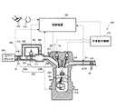
図1において、本発明に係る「内燃機関」の一例としてのエンジン200は、吸気通路部230を構成する吸気管206及び234、気筒201、排気管210、ターボ過給機を構成するコンプレッサ41及びタービン42、可変動弁機構110、本発明の「制御手段」の一例である制御装置100、スロットル弁214、サージタンク111、吸気弁203及び圧力センサ225、エアーバイパス300、本発明の「流量調節手段」の一例であるエアバイパスバルブ(以下、ABVと称す。)301、エアフローメータ(以下、AFMと称す。)302及び303を備えている。制御装置100、エアバイパスバルブ300、ABV301、及びAFM302が、本発明の「内燃機関の制御装置」の一例を構成しており、車両に搭載されている。 In FIG. 1, an
尚、図1では、説明の便宜上、エンジン200の気筒を一つのみ図示しているが、エンジン200は、4つの気筒を含む直列4気筒のエンジンである。これら複数の気筒の夫々に対応して設けられた複数の吸気弁203及び複数の排気弁204は、共通の可変動弁機構110によってリフト量及び作用角(即ち、リフト期間)を変更可能に構成されている。 In FIG. 1, for convenience of explanation, only one cylinder of the
吸気管234、サージタンク111、及び吸気管206は、エンジン200の外部から空気を気筒201に供給するための吸気通路部230を構成しており、エンジン200の動作時に、外部からエアクリーナ304を介して空気をエンジン200内に取り入れる。 The
吸気通路部230は、吸気通路部230のうちスロットル弁214の上流側に位置する第1通路部分230a、及び吸気通路部230のうちスロットル弁214の下流側に位置する第2通路部分230bから構成されている。 The
エアーバイパス300は、第1通路部分230a及び第2通路部分230bを相互に繋いでいる。即ち、エアーバイパス300は、第1通路部分230aを介して空気を第2通路部分230bに供給可能になるように吸気通路部230を迂回するように吸気通路部230に接続されている。 The
ABV301は、制御装置100の制御下で、エアーバイパス300を流れる空気の流量を調節可能に構成されている。したがって、エンジン200では、エンジン200の外部から気筒201に空気を供給する経路が、吸気通路部230及びエアーバイパス300の2系統設けられていることになる。ABV301は、例えば、機械的、或いは電磁的に駆動されるバルブ機構を有しており、制御装置100の制御下でその開閉動作が制御される。 The
吸気管206は、エンジン200の動作時に、吸気弁203の開閉によって気筒201内部との連通状態が制御されている。即ち、吸気管206において、外部から吸入された空気(即ち、吸入空気)と、燃料噴射装置であるインジェクタ211から噴射された燃料とが混合され(即ち、混合気を形成し)、吸気弁203を介して気筒201に供給される。アクセルポジションセンサ216は、運転者によるアクセルペダル226の踏み込み量、即ちアクセル開度を検出する。エンジン200を搭載した車両に加速要求がされたか否かは、アクセル開度に基づいて判断される。スロットルバルブモータ217は、アクセル226の踏み込み量に基づいてスロットル弁214を開閉駆動する。スロットル弁214は、吸気管234からサージタンク111へ送り込む空気の供給量を調節する。 The
サージタンク111は、空気を供給する吸気通路部の一部として各気筒に共用されており、各気筒へ送り込む空気を分配する他、分配される空気の圧力変動、即ち脈動を抑制する。スロットルポジションセンサ215は、スロットル弁214のスロットル開度を検出する。 The
気筒201は、その内部において、吸気管206から送られてきた混合気を、点火プラグ202により燃焼させることが可能に構成されている。この燃焼により、ピストン205は、気筒201内で上下に往復運動する。この往復運動がクランクシャフト219の回転運動に変換され、エンジン200が搭載された車両は、エンジン200から出力された回転運動に基づく駆動力によって駆動可能に構成されている。クランクポジションセンサ218は、クランクシャフト219の回転角(即ち、クランク角)を検出する。 The
排気管210は、気筒201内部で発生する排気ガスを、排気弁204を介して排気することが可能に構成されている。空燃費センサ221は、排気ガスの空燃比A/F2を検出して、制御装置100へ伝達可能に構成されている。こうして検出された空燃比A/F2は、例えばインジェクタ211によって噴射される燃焼量のフィードバック補正に利用される。 The
タービン42は、排気管210に配設されており、排気ガスの運動エネルギを受けて回転させられ、タービン42の回転トルクをコンプレッサ41の回転に変換可能に構成されている。コンプレッサ41は、吸気管234に配設されており、その回転によって吸気を圧縮させる(過給する)ことが可能である。 The
可変動弁機構110は、例えば可変動バルブ機構(VVT)であり、制御装置100の制御下で、吸気弁203及び排気弁204の動弁特性を変更可能に構成されている。加えて、可変動弁機構110は、アクチュエータによって駆動されるカムバイワイヤ(CambyWire)、或いは電磁駆動弁等の各気筒に共通の駆動部11によって、エンジン200を構成する複数の気筒の夫々に対応して設けられた複数の吸気弁203及び複数の排気弁204のリフト量及び作用角を変更可能に構成されている。 The
AFM302は、エアーバイパス300に設けられており、エアーバイパス300を流れる空気の流量を測定する。 The
制御装置100は、エンジン200の動作全体を制御する。周知の電子制御ユニット(Electronic Control Unit:ECU)、中央処理装置(Central Processing Unit:CPU)、制御プログラムを格納した読み出し専用メモリ(Read Only Memory:ROM)、各種データを格納する随時書き込み読み出しメモリ(Random Access Memory:RAM)等を中心とした論理演算回路として構成されている。 The
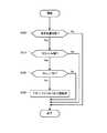
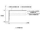
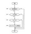
次に、図1乃至図8を参照しながら、本実施形態に係る内燃機関の制御装置の基本的な動作を説明する。図2は、本実施形態に係る内燃機関の制御装置によって実行可能な内燃機関の制御方法の主要な処理ルーチンを順に示したフローチャートである。図3は、図2に示したステップS120の詳細な処理ルーチンを順に示したフローチャートである。図4は、要求吸気量、吸気弁のリフト量、スロットル弁の開度、及びABVの開度の夫々の時間経過に対する変化を概念的に示した概念図である。図5は、吸気量及び空気の供給量の夫々の時間経過に対する変化を概念的に示した概念図である。尚、図5では、説明の便宜上、時間経過に対する吸気量の変化及び空気の供給量の変化を重ねて図示している。 Next, the basic operation of the control apparatus for an internal combustion engine according to the present embodiment will be described with reference to FIGS. FIG. 2 is a flowchart sequentially showing main processing routines of the control method for an internal combustion engine that can be executed by the control device for the internal combustion engine according to the present embodiment. FIG. 3 is a flowchart sequentially showing a detailed processing routine of step S120 shown in FIG. FIG. 4 is a conceptual diagram conceptually showing changes in the required intake air amount, the intake valve lift amount, the throttle valve opening, and the ABV opening over time. FIG. 5 is a conceptual diagram conceptually showing changes in the intake air amount and the air supply amount over time. In FIG. 5, for convenience of explanation, a change in the intake air amount and a change in the air supply amount over time are shown in an overlapping manner.
図1及び図2に示すように、制御装置100は、エンジン200が、スロットル弁214によって気筒201に対する吸気量が調節されている状態(即ち、低空気量状態)にあるか否かを判断する(ステップS100)。ここで、「低空気量状態」とは、例えば、車両がアイドリング運転されている状態、或いは、車両が一定の速度で走行している状態であって気筒に供給される吸気量の変動が小さく、且つ車両を加速させる際に比べて相対的に吸気量が少なくて済む状態をいう。車両がアイドリング運転されている場合には、各気筒の吸気弁203の開閉動作による吸気量のばらつきが低減された状態でスロットル弁214を絞ることによって実質的に各気筒に供給される吸気量が調節されている。 As shown in FIGS. 1 and 2, the
次に、制御装置100は、スロットル弁214が開いているか否かを判定する(ステップS110)。スロットル弁214が閉じている状態、言い換えれば、アクセル226に対する踏み込みに応じて車両に加速要求がなされていないと判定された場合には、本実施形態に係る内燃機関の制御方法を終了する。 Next, the
スロットル弁214が開いている状態、言い換えれば、アクセル226が踏み込みこまれることによって車両に加速要求がなされていると判定された場合には、制御装置100は、第2通路部分230b内の圧力Pimが所定の圧力P0より低いか否かを判定する(ステップS120)。第2通路部分230b内の圧力は、エンジン200の動作状態を規定するパターメータに基づいて制御装置100によって推定された推定値を用いる。 When the
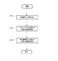
より具体的には、図3に示すように、制御装置100は、当該制御装置100が有するメモリ等の記憶部に記憶された空気量マップを読み出し(ステップS121)、ABV301を開くことによってエアーバイパス300に流れる空気の流量を推定する(ステップS122)。次に、制御装置100は、スロットル弁214を通過する空気の流量、即ち第1通路部分230aから直接第2通路部分230bに供給される空気の流量と、エアーバイパス300を流れる空気の流量とに基づいて第2通路部分230bに流れる空気の流量を推定する(ステップS123)ことによって、第2通路部分230b内の圧力Pimが推定される。尚、圧力センサ225を用いて測定された第2通路部分230b内の圧力Pimを用いてもよい。 More specifically, as shown in FIG. 3, the
次に、制御装置100は、圧力Pimが圧力P0より低いと判定された場合には、エンジン200に要求された要求トルクに応じてスロットル弁214が開く際に、第2通路部分230b内の圧力が高まるようにABV301を開く(ステップS130)。 Next, when it is determined that the pressure Pim is lower than the pressure P0, the
ここで、「要求トルクに応じてスロットル弁が開く際に」は、運転者が車両のアクセル226を踏み込むことによってエンジン200に要求されたトルクに応じて、気筒201に供給されるべき吸気量が急激に増大するタイミングであり、より具体的には、例えば、アイドリング状態から車両を急加速させるタイミングである。 Here, “when the throttle valve opens according to the required torque”, the amount of intake air to be supplied to the
吸気通路部230に吸入された空気は、ABV301が開くことによって、第1通路部分230aから直接第2通路部分230bに供給されるだけでなく、エアーバイパス300を介して第1通路部分230aから第2通路部分230bに供給される。 The air sucked into the
ここで、図4及び図5を参照しながら、ABV301を開くことによってエアーバイパス300から第2通路部分230bに空気が供給される場合と、空気が供給されない場合との夫々において気筒201に供給される空気の吸気量の違いについて説明する。 Here, referring to FIG. 4 and FIG. 5, the air is supplied to the
図4(a)に示すように、アクセル226を踏み込むことによって時刻T0にエンジン200にトルクの要求があった場合には、エンジン200に要求された要求トルクを気筒201内における燃料の燃焼によって出力するために、要求吸気量が吸気量Q1からQ2に急激に増大する。図4(b)に示すように、吸気弁203は、時刻T0から僅かに遅れる時刻T1に開き始め、そのリフト量は、リフト量LF0からLF1に増大する。時刻T0及びT1間における遅延時間Δtは、約32msecであり、要求吸気量に対して適切なリフト量、並びに、後述するスロットル開度及びABV開度を設定するための設定時間として用いられる。 As shown in FIG. 4A, when the
ここで、図5に示すように、第2通路部分230b内の圧力が高く、吸気弁203のリフト量に対して応答性良く空気が気筒201に吸気される場合には、気筒201に供給される吸気量は、変化線L1で示すように理想的な変化を示す。しかしながら、第2通路部分230b内の圧力Pimが圧力P0より低い場合には、吸気通路部230のうち吸気弁203の直前に位置する第2吸気通路部230b内に十分な空気が充填されておらず、アクセル226の踏み込み量に対して応答性良く空気が気筒201に供給されないことなり、エンジン200は、アクセル226の踏み込みに対して応答性良くトルクを発生させることが難しい。 Here, as shown in FIG. 5, when the pressure in the
そこで、本実施形態では、図4(c)に示すように、アクセル226の踏み込みに対してスロットル214が開くスロットル開度が増大するのと並行して、制御装置100の制御下で図4(d)に示すようにABV301を開く。 Therefore, in the present embodiment, as shown in FIG. 4C, the throttle opening degree of the
したがって、本実施形態に係る内燃機関の制御装置によれば、第2通路部分230bに対して第1通路部分230a及びエアーバイパス300の夫々を介して空気が供給されることになり、第1通路部分230aのみを介して第2通路部分230bに空気を供給する場合に比べて、相対的に多くの空気を第2通路部230b分に供給でき、第2通路部分230b内の圧力Pimを高めることが可能である。 Therefore, according to the control device for an internal combustion engine according to the present embodiment, air is supplied to the
より具体的には、図5に示すように、気筒201に供給される空気の吸気量は、ABVによる空気の供給量(図中、変化線L3)と、スロットル弁214による空気の供給量(図中、変化線L4)とを相互に加えることによって形成された補正後の吸気量変化線L2で示されるように変化する。変化線L2は、エアーバイパス300を介して第2通路部分230bに空気を供給しない場合に比べて、理想的な吸気量の変化線L1に近づけられている。 More specifically, as shown in FIG. 5, the amount of intake air supplied to the
したがって、本実施形態に係る内燃機関の制御装置によって実行可能な内燃機関の制御方法によれば、エンジン200に要求されたトルクを発生可能なように、要求トルクに応じた吸気量で空気が気筒201に供給されることになり、例えばアイドリング状態から車両を急加速させる場合のように低空気量状態から車両を急加速させる場合であっても、アクセル226の踏み込み量に対して応答性良くエンジン200にトルクを発生させることが可能になる。 Therefore, according to the control method for an internal combustion engine that can be executed by the control device for the internal combustion engine according to the present embodiment, the air is cylinderd with the intake amount corresponding to the required torque so that the torque required for the
よって、本実施形態に係る内燃機関の制御装置によれば、アイドリング状態から運転者によるアクセル踏み込み量に対して応答性良くトルクを発生させることができ、車両の加速性能を高めることが可能である。 Therefore, according to the control apparatus for an internal combustion engine according to the present embodiment, it is possible to generate torque with high responsiveness to the accelerator depression amount by the driver from the idling state, and it is possible to improve the acceleration performance of the vehicle. .
また、本実施形態に係る内燃機関の制御装置によれば、制御装置100は、エアーバイパス300を流れる空気の流量の推定値に基づいて、スロットル弁214を通過する空気の流量として測定された測定流量を補正し、補正された測定流量に基づいてエアーバイパス300を流れる空気の流れが遮断されるようにABV301を制御してもよい。 Further, according to the control device for an internal combustion engine according to the present embodiment, the
より具体的には、制御装置100は、エンジン200の動作状態を示す各種パラメータについてエアーバイパス300を流れる空気の流量を特定したマップに基づいてエアーバイパス300を流れる空気の流量を推定する。このようなマップは、制御装置100が備えるメモリ等の記憶部に記憶され、適時読み出される。 More specifically,
スロットル弁214を通過する空気の流量は、例えば、吸気通路部230のうちスロットル弁214の上流側に配置されたAFM303によって測定される。制御装置100は、AFM303によって測定された測定流量に基づいてエアーバイパス300を流れる空気の流れが遮断されるようにABV3012の開閉動作を制御する。より具体的には、制御装置100は、エアーバイパス300を流れる空気の流量の推定値に基づいて補正された補正済みの測定流量が所定値を超えた場合に、エアーバイパス300を流れる空気の流れを遮断するようにABV301を閉じる。 The flow rate of air passing through the
「所定値」とは、エアーバイパス300を介して空気を第2通路部分230bに供給しなくても、エンジン200に要求されたトルクに応じた吸気量を吸気弁203の開閉動作によって気筒201に吸気できる基準となる、スロットル弁214を通過する空気の流量をいう。 The “predetermined value” means that the intake air amount corresponding to the torque required for the
尚、スロットル弁214を通過する空気の流量としては、AFM303によって直接測定された測定値が用いられる場合だけに限定されず、エンジン200の動作状態を規定する各種パラメータに基づいて推定された推定値が用いられてもよい。勿論、AFM303によって空気の流量を直接測定したほうが、空気の補償を正確に実行することが可能であるが、推定値を用いた場合には、AFM303を吸気通路部230に設けなくてもよいため、内燃機関の制御装置の小型化が可能になる。 Note that the flow rate of the air passing through the
また、スロットル弁214を通過する空気の流量は、例えば、スロットル弁214の開度を示すスロットル開度に基づいてスロットル弁214を通過する空気の流量を推定した推定値を用いてもよい。スロットル開度から直接スロットル弁214を通過する空気の流量を特定した場合には、空気の流量に関する推定値を用いる場合に比べて、エアーバイパス300を流れる空気の流れをより適切なタイミングで遮断できる。 Further, as the flow rate of air passing through the
このようにABV301の開閉動作が制御されることによって、エンジン200に要求された要求トルクに応じてスロットル弁214が開いた時点から、エンジン200に要求されたトルクを発生させる状態にエンジン200の動作状態が移行するまでの間の過渡的な状態において、十分な空気が第2通路部分230bに供給された状態でABV301を閉じることによって、気筒201に供給される空気を補償しつつ、その後のエンジン200の動作を安定して行なうことが可能である。 By controlling the opening / closing operation of the
(変形例1)
次に、図6及び図7を参照しながら、本実施形態に係る内燃機関の制御装置によって実行可能な内燃機関の制御方法の変形例を説明する。図6は、本例に係る内燃機関の制御方法を実行した場合における、要求吸気量、スロットル開度及びABV開度の夫々の時間経過に対する変化を概念的に示した概念図である。図7は、吸気量及び空気の供給量の夫々の時間経過に対する変化を概念的に示した概念図である。尚、以下で説明する各変形例は、上述した内燃機関の制御装置と共通の構成を有する内燃機関の制御装置によって実行可能であるため、その詳細な構成の図示を省略する。(Modification 1)
Next, a modified example of the internal combustion engine control method that can be executed by the internal combustion engine control apparatus according to the present embodiment will be described with reference to FIGS. 6 and 7. FIG. 6 is a conceptual diagram conceptually showing changes in the required intake air amount, the throttle opening, and the ABV opening over time when the internal combustion engine control method according to this example is executed. FIG. 7 is a conceptual diagram conceptually showing changes in the intake air amount and the air supply amount over time. Each modified example described below can be executed by an internal combustion engine control device having the same configuration as that of the above-described internal combustion engine control device, and thus detailed illustration of the configuration is omitted.
図6(a)乃至(c)に示すように、制御装置100は、時刻T0に車両に加速要求がなされた場合、即ちエンジン200に要求される吸気量が、要求吸気量Q0からQ1に急激に増大した場合、スロットル開度SD0からSD1に急激に高めると共に、ABV301の開度を開度AD0から開度AD1に高める。言い換えれば、制御装置100は、上述した遅延時間Δtを設けることなく、スロットル弁214が開くタイミングにABV301を開き、エアーバイパス300を介して第2通路部分230bに空気を一気に供給する。 As shown in FIGS. 6 (a) to 6 (c), when the acceleration request is made to the vehicle at time T0, that is, the intake air amount required for the
このようにABV301を開くことによって、スロットル弁214が開くと同時にエアーバイパス300を介して第2通路部分230bに空気が供給されるため、吸気弁203を開くことのみによって、気筒201に供給される吸気量の時間に対する変化に沿うように気筒201に対して供給される吸気の吸気量を増やすことが可能である。 By opening the
より具体的には、図7に示すように、車両に加速要求がなされた時刻T0から即座に、理想的な吸気量変化線L1、即ち加速要求に応じた吸気量の変化を示す変化線に補正後の吸気量変化線L2を近づけることができる。このような補正後の変化線L2は、スロットル弁による空気の供給量変化線L4及びABV301による空気の供給量の変化線L3によって規定され、加速要求に応じて応答性良く当該加速要求に応じたトルクがエンジン200から出力される。したがって、スロットル弁214が開く時点から遅れてエアーバイパス300から空気を第2通路部分230bに供給する場合に比べて、加速要求に対するエンジン200の応答性を高めることが可能である。 More specifically, as shown in FIG. 7, immediately after the time T0 when the vehicle is requested to accelerate, an ideal intake air amount change line L1, that is, a change line indicating a change in the intake air amount in response to the acceleration request. The corrected intake air amount change line L2 can be brought closer. The corrected change line L2 is defined by the air supply amount change line L4 by the throttle valve and the air supply amount change line L3 by the
(変形例2)
次に、図8及び図9を参照しながら、本実施形態に係る内燃機関の制御装置によって実行可能な内燃機関の制御方法の他の例を説明する。図8は、本例に係る内燃機関の制御方法の主要な処理ルーチンを示したフローチャートである。図9は、本例に係る内燃機関の制御方法を実行した場合における、スロットル開度、吸気通路部内の圧力、燃料噴射量、及びABVの開閉状態の夫々の時間経過に対する変化を概念的に示した概念図である。尚、
以下で説明する内燃機関の制御方法は、上述した内燃機関の制御方法に相前後して連続した手順で実行される。(Modification 2)
Next, another example of the internal combustion engine control method that can be executed by the internal combustion engine control apparatus according to the present embodiment will be described with reference to FIGS. 8 and 9. FIG. 8 is a flowchart showing a main processing routine of the control method of the internal combustion engine according to this example. FIG. 9 conceptually shows changes in the throttle opening, the pressure in the intake passage, the fuel injection amount, and the open / closed state of the ABV with respect to time when the internal combustion engine control method according to this example is executed. It is a conceptual diagram. still,
The internal combustion engine control method described below is executed in a sequence that follows the above-described internal combustion engine control method.
図8に示すように、制御装置100は、エンジン200が、スロットル弁214によって気筒201に対する吸気量が調節されている状態(即ち、低空気量状態)にあるか否かを判定する(ステップS200)。エンジン200が低空気量状態ではないと判定された場合には、本例に係る内燃機関の制御方法を終了する。エンジン200が、低空気量状態であると判定された場合には、制御装置100は、スロットル弁214が閉まっているか否かを判定する(ステップS210)。即ち、制御装置100は、エンジン200を搭載する車両に加速要求がなされたか否かを判定する。スロットル弁214が開いている場合、即ち、車両に減速要求がなされていない場合には、本例に係る内燃機関の制御方法を終了する。 As shown in FIG. 8, the
スロットル弁214が閉まっていると判定された場合、即ち、車両に減速要求がなされたと判定された場合には、制御装置100は、第2通路部分230b内の圧力Pimが所定の圧力P0より低いか否かを判定する(ステップS220)。圧力PimがP0以上であると判定された場合には、本例に係る内燃機関の制御方法を終了する。圧力Pimが圧力P0より低いと判定された場合には、制御装置100の制御下でABV301を開く(ステップS230)。 When it is determined that the
ここで、図9を参照しながら、ABV301を開くタイミングについて詳細に説明する。 Here, the timing for opening the
図9において、スロットル開度が開度SD1からSD2に切り換わった場合、即ち車両に減速要求がなされた時刻T2(図9(a)参照。)において、吸気通路部230内の圧力は急激に低下する(図9(b)参照。)。インジェクタ211によって実行される燃料の噴射量は、時刻T2から遅れた時刻T3で噴射量F1からF2に低下する(即ち、フューエルカットされる。)。したがって、時刻T2及びT3間では、第2通路部分230bにおける雰囲気は、図9(c)中においてハッチングで示した範囲で噴射された燃料分だけ燃料が過剰にインジェクタ211から噴射された燃料リッチ状態となる。そこで、本例に係る内燃機関の制御方法によれば、制御装置100は、車両が減速する際に、スロットル弁214が閉じてから気筒201に対する燃料の供給が停止されるまでの期間においてエアーバイパス300を流れる空気の流量が増えるようにABV301を開き、燃料リッチ状態を解消する。 In FIG. 9, when the throttle opening degree is switched from the opening degree SD1 to SD2, that is, at time T2 when the vehicle is requested to decelerate (see FIG. 9 (a)), the pressure in the
本例に係る内燃機関の制御方法によれば、スロットル弁214を閉じてから気筒201に対する燃料の供給が停止(即ち、フューエルカット)されるまでの期間において、第2通路部分230bより下流側の圧力、より具体的には第2通路部分230b及び気筒201内の燃焼室の圧力が負圧側に増大した場合でも、当該燃焼室において燃料の濃度が増大することを低減できる。したがって、燃料の供給を停止することによってエンジン200に生じる衝撃、燃料の消費量、及びオイル消費量を低減できる。 According to the control method for an internal combustion engine according to the present example, the fuel supply to the
<第2実施形態>
次に、図10を参照しながら、本発明の第2の発明に係る内燃機関の制御装置の実施形態を説明する。図10は、本発明の実施形態に係る内燃機関(即ち、エンジン)の制御装置が適用された内燃機関の模式的な平面図である。尚、以下では、上述した第1実施形態に係る内燃機関の制御装置と共通する部分に共通の参照符号を付し、詳細な説明を省略する。Second Embodiment
Next, an embodiment of a control device for an internal combustion engine according to the second invention of the present invention will be described with reference to FIG. FIG. 10 is a schematic plan view of an internal combustion engine to which an internal combustion engine (that is, engine) control device according to an embodiment of the present invention is applied. In the following description, common reference numerals are assigned to portions common to the control device for an internal combustion engine according to the first embodiment described above, and detailed description thereof is omitted.
図10において、エンジン200aは、第2通路部分230bに形成された空気取り込み口部310、及び本発明の「空気取り込み手段」の一例であるフィルタ311、並びに制御装置100aを備えている。空気取り込み口部310、及びフィルタ311、並びに制御装置100aが、本発明の第2の発明に係る「内燃機関の制御装置」の一例を構成している。 10, the
制御装置100aは、スロットル弁214によって吸気量が調節されている状態において、エンジン200aに要求された要求トルクに応じてスロットル弁214が開くようにスロットル弁214の開閉動作を制御する。より具体的には、アクセル226の踏み込み量に応じてスロットル弁214が開くように所定の制御信号をスロットルバルブモータ217に送信し、スロットル弁214を開く。 The
フィルタ311は、吸気通路部230のうちスロットル弁214の下流側に位置する第2通路部分230bに空気を取り込むために設けられた空気取り込み口部310に設けられている。フィルタ311は、要求トルクがエンジン200aに要求された際に第2通路部分230b内の圧力及び大気圧の圧力差に応じて吸気通路部230の外部から第2通路部分230bに空気を取り込み可能となるように開く。フィルタ311は、吸気通路部230内の圧力と、吸気通路部230の外部の圧力との圧力差に応じて開閉動作が可能であるフィルタである。このようなフィルタ311は、第2通路部分230b内の圧力及び大気圧の圧力差に応じて外部から開き、第2通路部分230b内に外部から空気を取り込む。 The
したがって、本実施形態に係る内燃機関の制御装置によれば、フィルタ311の開閉動作を制御装置100aによって制御しなくても、吸気通路部230及び外部の夫々の圧力の差に応じて空気取り込み口部310を介して第2通路部分230b内に空気を取り込むことが可能である。よって、上述した第1実施形態に係る内燃機関の制御装置と同様に、アイドリング状態から運転者によるアクセル踏み込み量に対して応答性良くトルクを発生させることができ、車両の加速性能を高めることが可能である。 Therefore, according to the control device for an internal combustion engine according to the present embodiment, the air intake port can be adjusted according to the pressure difference between the
尚、本実施形態に係る内縁機関の制御装置によれば、制御装置100aは、第2吸気通路部230bにおいて、スロットル弁214を通過する空気の流量が所定値を超えた際に、空気取り込み口部310を介して第2通路部分230bに空気が取り込まれないようにフィルタ311の開閉動作を制御してもよい。 Note that, according to the control device for an inner edge engine according to the present embodiment, the
スロットル弁214を通過する空気の流量が所定値を超えた際に、フィルタ311が閉じられることによって、第1通路部分230aを介して供給される空気のみによって応答性良くエンジン200aにトルクを出力させることが可能である。 When the flow rate of air passing through the
100,100a・・・制御装置、110・・・可変動弁機構、230・・・吸気通路、230a・・・第1通路部分、230b・・・第2通路部分、302,303・・・エアフローメータ(AFM)、311・・・フィルタ DESCRIPTION OF SYMBOLS 100,100a ... Control apparatus, 110 ... Variable valve mechanism, 230 ... Intake passage, 230a ... First passage part, 230b ... Second passage part, 302, 303 ... Air flow Meter (AFM), 311 ... Filter
Claims (8)
Translated fromJapanese前記吸気通路部のうち前記スロットル弁の上流側に位置する第1通路部分、及び前記吸気通路部のうち前記スロットル弁の下流側に位置する第2通路部分を相互に繋ぐエアーバイパスと、
前記エアーバイパスを流れる空気の流量を調節可能な流量調節手段と、
前記スロットル弁によって前記吸気量が調節されている状態において、前記内燃機関に要求された要求トルクに応じて前記スロットル弁が開く際に、前記第2通路部分内の圧力が高まるように前記流量調節手段を制御する制御手段と
を備えたことを特徴とする内燃機関の制御装置。A throttle valve provided in the middle of an intake passage for supplying air to the cylinder, and a variable valve mechanism for opening and closing an intake valve capable of adjusting an intake air amount supplied to the cylinder, and a vehicle A control device for an internal combustion engine for controlling the internal combustion engine mounted on the vehicle,
An air bypass connecting the first passage portion located upstream of the throttle valve in the intake passage portion and the second passage portion located downstream of the throttle valve in the intake passage portion;
Flow rate adjusting means capable of adjusting the flow rate of air flowing through the air bypass;
In the state where the intake air amount is adjusted by the throttle valve, the flow rate adjustment is performed so that the pressure in the second passage portion increases when the throttle valve opens according to the required torque required for the internal combustion engine. An internal combustion engine control apparatus comprising: control means for controlling the means.
を特徴とする請求項1に記載の内燃機関の制御装置。The control means controls the flow rate adjusting means so that the flow of air flowing through the air bypass is interrupted when the flow rate of air passing through the throttle valve in the intake passage portion exceeds a predetermined value. The control device for an internal combustion engine according to claim 1.
を特徴とする請求項2に記載の内燃機関の制御装置。The control unit corrects a measured flow rate measured as a flow rate of air passing through the throttle valve based on an estimated value of a flow rate of air flowing through the air bypass, and the air flow is corrected based on the corrected measured flow rate. The control device for an internal combustion engine according to claim 2, wherein the flow rate adjusting means is controlled so that the flow of air flowing through the bypass is cut off.
前記制御手段は、前記エアーバイパスを流れる空気の流量の測定値に基づいて、前記スロットル弁を通過する空気の流量として測定された測定流量を補正し、該補正された測定流量に基づいて前記エアーバイパスを流れる空気の流れが遮断されるように前記流量調節手段を制御すること
を特徴とする請求項2に記載の内燃機関の制御装置。Provided in the air bypass, further comprising an air flow meter for measuring a flow rate of air flowing through the air bypass;
The control means corrects the measured flow rate measured as the flow rate of air passing through the throttle valve based on the measured value of the flow rate of air flowing through the air bypass, and the air flow is corrected based on the corrected measured flow rate. The control device for an internal combustion engine according to claim 2, wherein the flow rate adjusting means is controlled so that the flow of air flowing through the bypass is cut off.
を特徴とする請求項1から4の何れか一項に記載の内燃機関の制御装置。5. The internal combustion engine according to claim 1, wherein the control unit controls the flow rate adjusting unit so that air flows into the air bypass simultaneously with the opening of the throttle valve. 6. Control device.
を特徴とする請求項1から5の何れか一項に記載の内燃機関の制御装置。When the vehicle decelerates, the control means adjusts the flow rate so that the flow rate of air flowing through the air bypass increases during a period from when the throttle valve is closed until fuel supply to the cylinder is stopped. The control device for an internal combustion engine according to any one of claims 1 to 5, wherein:
前記スロットル弁によって前記吸気量が調節されている状態において、前記内燃機関に要求された要求トルクに応じて前記スロットル弁が開くように前記スロットル弁の開閉動作を制御する制御手段と、
前記吸気通路部のうち前記スロットル弁の下流側に位置する通路部分に空気を取り込むために設けられた空気取り込み口部に設けられており、前記要求トルクが前記内燃機関に要求された際に前記通路部分内の圧力及び大気圧の圧力差に応じて外部から前記通路部分に空気を取り込む空気取り込み手段と
を備えたことを特徴とする内燃機関の制御装置。A throttle valve provided in the middle of an intake passage for supplying air to the cylinder, and a variable valve mechanism for opening and closing an intake valve capable of adjusting an intake air amount supplied to the cylinder, and a vehicle A control device for an internal combustion engine for controlling the internal combustion engine mounted on the vehicle,
Control means for controlling the opening / closing operation of the throttle valve so that the throttle valve is opened in accordance with a required torque required for the internal combustion engine in a state where the intake air amount is adjusted by the throttle valve;
The intake passage portion is provided in an air intake port portion provided for taking air into a passage portion located downstream of the throttle valve, and when the required torque is requested from the internal combustion engine, An internal combustion engine control device comprising: an air intake means for taking air into the passage portion from the outside in accordance with a pressure difference between the pressure in the passage portion and the atmospheric pressure.
を特徴とする請求項7に記載の内燃機関の制御装置。The control means is configured to prevent the air from being taken into the passage portion through the air intake port when the flow rate of air passing through the throttle valve exceeds a predetermined value in the intake passage portion. The control device for an internal combustion engine according to claim 7, wherein the intake means is controlled.
Priority Applications (1)
| Application Number | Priority Date | Filing Date | Title |
|---|---|---|---|
| JP2007133706AJP2008286149A (en) | 2007-05-21 | 2007-05-21 | Control device for internal combustion engine |
Applications Claiming Priority (1)
| Application Number | Priority Date | Filing Date | Title |
|---|---|---|---|
| JP2007133706AJP2008286149A (en) | 2007-05-21 | 2007-05-21 | Control device for internal combustion engine |
Publications (1)
| Publication Number | Publication Date |
|---|---|
| JP2008286149Atrue JP2008286149A (en) | 2008-11-27 |
Family
ID=40146087
Family Applications (1)
| Application Number | Title | Priority Date | Filing Date |
|---|---|---|---|
| JP2007133706APendingJP2008286149A (en) | 2007-05-21 | 2007-05-21 | Control device for internal combustion engine |
Country Status (1)
| Country | Link |
|---|---|
| JP (1) | JP2008286149A (en) |
Cited By (3)
| Publication number | Priority date | Publication date | Assignee | Title |
|---|---|---|---|---|
| WO2010146719A1 (en)* | 2009-06-15 | 2010-12-23 | トヨタ自動車株式会社 | Spark ignition type internal combustion engine |
| RU2442002C2 (en)* | 2009-06-15 | 2012-02-10 | Тойота Дзидося Кабусики Кайся | Spark ignition internal combustion engine |
| US10738686B2 (en) | 2017-11-20 | 2020-08-11 | Toyota Jidosha Kabushiki Kaisha | Internal combustion engine controller |
- 2007
- 2007-05-21JPJP2007133706Apatent/JP2008286149A/enactivePending
Cited By (6)
| Publication number | Priority date | Publication date | Assignee | Title |
|---|---|---|---|---|
| WO2010146719A1 (en)* | 2009-06-15 | 2010-12-23 | トヨタ自動車株式会社 | Spark ignition type internal combustion engine |
| RU2442002C2 (en)* | 2009-06-15 | 2012-02-10 | Тойота Дзидося Кабусики Кайся | Spark ignition internal combustion engine |
| US8229649B2 (en) | 2009-06-15 | 2012-07-24 | Toyota Jidosha Kabushiki Kaisha | Spark ignition type internal combustion engine |
| DE112009001849B4 (en)* | 2009-06-15 | 2013-07-18 | Toyota Jidosha Kabushiki Kaisha | Combustion engine of spark ignition design |
| DE112009001849B8 (en)* | 2009-06-15 | 2013-10-17 | Toyota Jidosha Kabushiki Kaisha | Combustion engine of spark ignition design |
| US10738686B2 (en) | 2017-11-20 | 2020-08-11 | Toyota Jidosha Kabushiki Kaisha | Internal combustion engine controller |
Similar Documents
| Publication | Publication Date | Title |
|---|---|---|
| US8607766B2 (en) | Control apparatus for an internal combustion engine | |
| US6691022B2 (en) | Intake air quantity measurement for internal combustion engine | |
| US9506412B2 (en) | Control apparatus for internal combustion engine | |
| JP5949218B2 (en) | Engine control device | |
| JPH04318264A (en) | Fuel control method in hydrogen engine | |
| WO2005085618A8 (en) | Method and device for controlling the air flow quantity of internal combustion engines | |
| CN104100384B (en) | Reduce enrichment caused by being constrained by minimum pulse width | |
| CN100570132C (en) | engine control unit | |
| JP2005240665A (en) | Variable valve operating device for internal combustion engine | |
| US7712446B2 (en) | Control device and method of controlling an internal combustion engine | |
| JP2008286149A (en) | Control device for internal combustion engine | |
| US7398749B2 (en) | Method and device for controlling an internal combustion engine | |
| JP3601386B2 (en) | Engine intake air control system | |
| JP4045962B2 (en) | Fuel injection control device for in-cylinder internal combustion engine | |
| JP4066764B2 (en) | Control device for internal combustion engine | |
| JP6941652B2 (en) | Supercharging pressure setting device | |
| JP5376171B2 (en) | Vehicle output control device | |
| JP5333784B2 (en) | Vehicle intake air amount control device | |
| JP2008196338A (en) | Control device for internal combustion engine | |
| JP4133288B2 (en) | Variable valve timing control method for internal combustion engine | |
| JP3572996B2 (en) | Throttle control device for internal combustion engine | |
| JP2008202446A (en) | Control device for internal combustion engine | |
| JP3463474B2 (en) | Intake air amount control device for internal combustion engine | |
| JP2021102952A (en) | Control device of internal combustion engine | |
| JP3953991B2 (en) | Intake air amount control device for internal combustion engine |