JP2008266516A - Gasification furnace, gasification power plant, gasification apparatus, and operation method of gasification furnace - Google Patents
Gasification furnace, gasification power plant, gasification apparatus, and operation method of gasification furnaceDownload PDFInfo
- Publication number
- JP2008266516A JP2008266516AJP2007114257AJP2007114257AJP2008266516AJP 2008266516 AJP2008266516 AJP 2008266516AJP 2007114257 AJP2007114257 AJP 2007114257AJP 2007114257 AJP2007114257 AJP 2007114257AJP 2008266516 AJP2008266516 AJP 2008266516A
- Authority
- JP
- Japan
- Prior art keywords
- gasification
- slag
- gasification furnace
- gas
- slag tap
- Prior art date
- Legal status (The legal status is an assumption and is not a legal conclusion. Google has not performed a legal analysis and makes no representation as to the accuracy of the status listed.)
- Granted
Links
Images


Classifications
- Y—GENERAL TAGGING OF NEW TECHNOLOGICAL DEVELOPMENTS; GENERAL TAGGING OF CROSS-SECTIONAL TECHNOLOGIES SPANNING OVER SEVERAL SECTIONS OF THE IPC; TECHNICAL SUBJECTS COVERED BY FORMER USPC CROSS-REFERENCE ART COLLECTIONS [XRACs] AND DIGESTS
- Y02—TECHNOLOGIES OR APPLICATIONS FOR MITIGATION OR ADAPTATION AGAINST CLIMATE CHANGE
- Y02E—REDUCTION OF GREENHOUSE GAS [GHG] EMISSIONS, RELATED TO ENERGY GENERATION, TRANSMISSION OR DISTRIBUTION
- Y02E20/00—Combustion technologies with mitigation potential
- Y02E20/16—Combined cycle power plant [CCPP], or combined cycle gas turbine [CCGT]
- Y02E20/18—Integrated gasification combined cycle [IGCC], e.g. combined with carbon capture and storage [CCS]
- Y—GENERAL TAGGING OF NEW TECHNOLOGICAL DEVELOPMENTS; GENERAL TAGGING OF CROSS-SECTIONAL TECHNOLOGIES SPANNING OVER SEVERAL SECTIONS OF THE IPC; TECHNICAL SUBJECTS COVERED BY FORMER USPC CROSS-REFERENCE ART COLLECTIONS [XRACs] AND DIGESTS
- Y02—TECHNOLOGIES OR APPLICATIONS FOR MITIGATION OR ADAPTATION AGAINST CLIMATE CHANGE
- Y02P—CLIMATE CHANGE MITIGATION TECHNOLOGIES IN THE PRODUCTION OR PROCESSING OF GOODS
- Y02P20/00—Technologies relating to chemical industry
- Y02P20/10—Process efficiency
Landscapes
- Gasification And Melting Of Waste (AREA)
Abstract
Translated fromJapaneseDescription
Translated fromJapanese本発明は、有機物をガス化し、無機物を溶融スラグ化するガス化炉と、ガス化発電プラント、ガス化装置及びガス化炉の運転方法に関する。 The present invention relates to a gasification furnace that gasifies an organic substance and converts an inorganic substance into a molten slag, a gasification power plant, a gasification apparatus, and an operation method of the gasification furnace.
ガス化炉では、スラグタップで溶融スラグを安定流下させるために、スラグタップ下面を保温する必要がある。スラグタップ直下のクエンチ部にはバーナが設置されているものの、エネルギー効率を高めるため、起動・停止時や低負荷運転時にのみ燃料が使用されるのが通例である。 In the gasification furnace, it is necessary to keep the bottom surface of the slag tap warm in order to allow the molten slag to flow stably with the slag tap. Although a burner is installed in the quenching section directly under the slag tap, in order to increase energy efficiency, fuel is usually used only during start / stop and low-load operation.
スラグタップ下面を保温するために、クエンチ部に酸素含有ガスを供給し、スラグタップからクエンチ部に流入するガスに含まれる粒子を燃焼させて、スラグタップ付近を高温に保持することが提案されている(例えば、特許文献1参照)。 In order to keep the bottom surface of the slag tap warm, it has been proposed to supply oxygen-containing gas to the quench part and burn particles contained in the gas flowing into the quench part from the slag tap to keep the vicinity of the slag tap at a high temperature. (For example, refer to Patent Document 1).
また、クエンチ部にバーナを設置し、ガス化炉でガス化した生成ガスと酸化剤を投入してスラグタップを保温することが提案されている(例えば、特許文献2参照)
特許文献1には、スラグタップ監視装置に酸素含有ガスを噴射するノズルを設けて酸素含有ガスを噴射すると共に、起動用バーナ及びスラグ排出孔ノズルの一方又は両方から酸素含有ガスを噴射することが記載されている。 In Patent Document 1, a nozzle for injecting an oxygen-containing gas is provided in the slag tap monitoring device to inject the oxygen-containing gas, and the oxygen-containing gas is injected from one or both of the activation burner and the slag discharge hole nozzle. Are listed.
特許文献2に記載の発明は、クエンチ部に設置したバーナ自体で燃焼ガスを生成して、その燃焼ガスによりスラグタップを保温するものである。 In the invention described in
本発明の目的は、クエンチ部に助燃燃料を投入することなく、スラグタップを保温できるようにしてエネルギー効率の悪化を抑制し、しかも、少ないガス量でスラグタップ下面を保温し、スラグの安定流下を実現できるようにしたガス化炉と、ガス化発電プラント、ガス化装置及びガス化炉の運転方法を提供することにある。 The purpose of the present invention is to suppress the deterioration of energy efficiency by allowing the slag tap to be kept warm without introducing auxiliary fuel into the quenching section, and also to keep the lower surface of the slag tap warm with a small amount of gas so that the slag can flow stably. Is to provide a gasification furnace, a gasification power plant, a gasification apparatus, and a gasification furnace operation method.
本発明は、有機物をガス化し、無機物を溶融スラグにするガス化部と、このガス化部の底部にあり、有機物がガス化して生成された生成ガスの一部とともに溶融スラグを流下させるスラグタップと、スラグタップの下部にあるクエンチ部と、クエンチ部の下部にある水槽とを具備するガス化炉において、前記クエンチ部に少なくとも1本のノズル又はバーナを備え、そのノズル又はバーナから酸素を含む気体の噴流を水平方向に供給するようにしたものである。 The present invention relates to a gasification unit that gasifies organic matter and converts inorganic matter into molten slag, and a slag tap that is located at the bottom of the gasification unit and flows down the molten slag together with a part of the product gas generated by gasification of the organic matter And a quenching section at the bottom of the slag tap and a water tank at the bottom of the quenching section, the quenching section includes at least one nozzle or burner, and oxygen is contained from the nozzle or burner. A gas jet is supplied in the horizontal direction.
本発明は、前記した構成のガス化炉と、ガス化炉で発生した生成ガスの熱回収設備と、脱塵設備及び脱硫設備と、脱塵及び脱硫処理された生成ガスを燃焼させて駆動するガスタービンと、ガスタービンで駆動する発電機及び圧縮機とを具備するガス化発電プラントにおいて、前記圧縮機から抽気した空気を昇圧して前記ガス化炉のクエンチ部に設置されたノズル又はバーナに供給する系統と、前記昇圧した空気に酸素を富化して前記ノズル又はバーナに供給する系統及び、前記圧縮機で抽気した空気を空気分離設備に供給して酸素及び窒素を製造して前記ノズル又はバーナに供給する系統のいずれかを備えるようにしたものである。 The present invention is driven by burning the gasification furnace having the above-described configuration, the heat recovery equipment for the generated gas generated in the gasification furnace, the dedusting equipment and the desulfurization equipment, and the degassed and desulfurized product gas. In a gasification power plant comprising a gas turbine, a generator driven by the gas turbine, and a compressor, the air extracted from the compressor is pressurized to a nozzle or burner installed in the quenching section of the gasification furnace. A supply system, a system for enriching the pressurized air with oxygen and supplying the nozzle or burner, and supplying air extracted by the compressor to an air separation facility to produce oxygen and nitrogen to produce the nozzle or One of the systems that supply the burner is provided.
本発明は、前記した構成のガス化炉と、ガス化炉のガス化部内とスラグタップ内、及びクエンチ部内の温度及び圧力を計測する計測装置と、前記ガス化炉から回収したスラグの重量を計測する計測装置と、ガス化炉のクエンチ部に落下するスラグの撮影装置と、前記温度と圧力とスラグ重量及びスラグ画像に基づいて、ガス化炉のクエンチ部に設置されたノズル又はバーナに供給する酸素、窒素、空気の流量を独立に制御する制御装置とを備えたガス化装置にある。 The present invention includes a gasification furnace having the above-described configuration, a measuring device for measuring the temperature and pressure in the gasification section and the slag tap of the gasification furnace, and the quench section, and the weight of the slag recovered from the gasification furnace. Supply to nozzle or burner installed in quenching section of gasification furnace based on measuring device to measure, imaging device of slag falling in quenching section of gasification furnace, and temperature, pressure, slag weight and slag image And a control device that independently controls the flow rates of oxygen, nitrogen, and air.
本発明において、スラグタップは、小判型の開口部を有するものが非常に好ましい。 In the present invention, the slag tap having an oval opening is very preferable.
本発明のガス化炉では、クエンチ部内において、スラグタップ下面に向かう酸素含有ガスの上昇流が形成され、ガス化部からスラグタップを下降する生成ガスと、スラグタップ下面付近で混合するようになる。これにより、助燃燃料を用いずに、少ないガス量で、スラグタップ下面付近を局所的に加熱できるようになり、エネルギー効率に優れるガス化炉となる。 In the gasification furnace of the present invention, an oxygen-containing gas upward flow toward the lower surface of the slag tap is formed in the quench portion, and the generated gas that descends the slag tap from the gasification portion is mixed in the vicinity of the lower surface of the slag tap. . Thereby, it becomes possible to locally heat the vicinity of the lower surface of the slag tap with a small amount of gas without using auxiliary combustion fuel, and a gasification furnace having excellent energy efficiency can be obtained.
本発明のガス化炉において、酸素を含む気体を供給するバーナ又はノズルは、1本ないしは複数本を備えることができる。複数本備える場合には、クエンチ部の同一円周上に等間隔又は略等間隔で配置することが望ましい。等間隔又は概略等間隔で配置することが望ましいのは、対向するノズル又はバーナからの噴流同士が衝突し、これにより、スラグタップ直下で、スラグタップを流下した生成ガスと酸素とが緩慢混合するようになり、少ないガス量で、スラグタップ下面を保温できるからである。 In the gasification furnace of the present invention, one or more burners or nozzles for supplying a gas containing oxygen can be provided. When providing a plurality, it is desirable to arrange them at equal intervals or substantially equal intervals on the same circumference of the quench portion. It is desirable to arrange them at equal intervals or approximately equal intervals. Jets from opposing nozzles or burners collide with each other, so that the product gas flowing down the slag tap and oxygen are slowly mixed just below the slag tap. This is because the lower surface of the slag tap can be kept warm with a small amount of gas.
クエンチ部に設置されるノズル又はバーナからは、酸素を含む気体とともに、ガス化炉生成ガスの一部を供給できるようにしてもよい。この場合には、可燃性の生成ガスが酸素を含む気体に同伴されて、スラグタップ直下に上昇し、スラグタップの下面付近で燃焼するようになる。これにより、燃料を用いずに、スラグタップ下面の保温効果を高めることができる。 You may enable it to supply a part of gasifier production | generation gas with the gas containing oxygen from the nozzle or burner installed in a quench part. In this case, the combustible product gas is accompanied by a gas containing oxygen, rises directly below the slag tap, and burns near the lower surface of the slag tap. Thereby, the heat retention effect of the slag tap lower surface can be enhanced without using fuel.
クエンチ部の同一円周上に等間隔又は略等間隔で設置された複数本のノズル又はバーナを、酸素を含む気体の運動量が独立に制御できる構成とすることも極めて望ましい。これにより、対向するノズル又はバーナからの噴流同士が衝突する位置を調整することができる。検討の結果、対向するノズル又はバーナのうち一方の前記運動量を大にし、他方の前記運動量を小にして、図7のようにスラグタップ直下から離れた位置で、それらの噴流同士を衝突させた場合には、図3のようにスラグタップ直下で噴流を衝突させた場合よりも、少ないガス量でスラグタップを保温できることがわかった。 It is also highly desirable that a plurality of nozzles or burners installed on the same circumference of the quench section at equal intervals or substantially equal intervals can independently control the momentum of the gas containing oxygen. Thereby, the position where the jets from an opposing nozzle or burner collide can be adjusted. As a result of the study, the momentum of one of the opposing nozzles or burners was increased and the other momentum was decreased, and the jets collided with each other at a position away from immediately below the slag tap as shown in FIG. In this case, it was found that the slag tap can be kept warm with a smaller amount of gas than the case where the jet collides directly under the slag tap as shown in FIG.
本発明では、他の実施形態として、酸素含有気体を噴出するノズル又はバーナを、その設置角度が、水平方向を基準に上方0°から45°までの範囲で可変となるように設置することを提案する。この場合には、ノズル又はバーナからの酸素を含む気体の噴流が、水平方向ないしはスラグタップを直撃しない範囲でスラグタップ方向に向けて供給されるようにする。酸素含有気体の噴流がスラグタップを直撃しないようにするのは、スラグタップ下面の溶損、および溶融スラグの飛散の恐れがあるためである。 In the present invention, as another embodiment, the nozzle or burner for ejecting the oxygen-containing gas is installed such that the installation angle is variable in the range from 0 ° to 45 ° above the horizontal direction. suggest. In this case, a gas jet containing oxygen from the nozzle or burner is supplied in the horizontal direction or in the direction of the slag tap in a range where the slag tap is not directly hit. The reason why the jet of oxygen-containing gas is prevented from directly hitting the slag tap is that there is a risk of melting of the lower surface of the slag tap and scattering of the molten slag.
クエンチ部には、非常時用のノズルを設けることもできる。非常時とは、例えば、ガス化部での旋回流の流速低下により、スラグタップを流下する生成ガスの流量が低下した場合である。非常時用のノズルは、使用時のみクエンチ部に挿入できるように、クエンチ部に出し入れ可能な構成にすることが望ましい。また、非常時用のノズルからは、酸素を含む気体もしくはガス化炉生成ガスの一部を供給することが望ましい。 The quenching section can be provided with an emergency nozzle. The emergency is, for example, a case where the flow rate of the product gas flowing down the slag tap is reduced due to a decrease in the flow velocity of the swirling flow in the gasification section. It is desirable that the emergency nozzle be configured so that it can be inserted into and withdrawn from the quenching section so that it can be inserted into the quenching section only during use. Moreover, it is desirable to supply a gas containing oxygen or a part of gasifier-produced gas from the emergency nozzle.
以下、本発明を石炭ガス化炉に適用した場合について、図面を用いて説明する。 Hereinafter, the case where this invention is applied to a coal gasification furnace is demonstrated using drawing.
本実施例は、既存の助燃バーナを用い、燃料を使用せずに、かつ、少ないガス量で、スラグタップ下面付近を局所的に加熱するようにしたものであり、エネルギー効率に優れている。 In this embodiment, an existing auxiliary burner is used, the fuel is not used, and the vicinity of the lower surface of the slag tap is locally heated with a small amount of gas, which is excellent in energy efficiency.
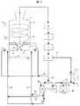
図1は、スラグタップ保温のためにクエンチ部に加熱バーナを設置したガス化炉の断面図を示す。ガス化部2には上段バーナ6と下段バーナ7が取り付けられており、各バーナより円筒型のガス化炉の接線方向に石炭、窒素、酸素が投入され、旋回流が形成される。投入された石炭は、ガス化部2においてガス化し、CO及H2を主成分とする生成ガス8となり、ガス化部2内を旋回しながら下降する。ガス化部2での旋回流の影響により、ガス化部2およびスラグタップ3内の圧力分布は、外側で高く、中心側で低くなる。FIG. 1 shows a cross-sectional view of a gasification furnace in which a heating burner is installed in a quenching section to keep slag taps warm. An
下降する生成ガス8の流れは、ガス化部2の底面に設置されたスラグタップ3にて反転し、ガス化部2の中心部を上昇する。一方、生成ガス8の一部は、スラグタップ3を下降し、直下のクエンチ部4に流入する。スラグタップを下降する生成ガスを、下降生成ガス9と呼ぶこととする。 The flow of the
クエンチ部4には、加熱バーナ10が設置されている。加熱バーナ10は、起動・停止時やガス化炉1を低負荷で運転する際に、助燃バーナとして軽油、酸素、窒素を投入し、スラグタップ3及びガス化部2の下部を加熱する役割を持つ。ガス化炉1を所定の負荷以上で運転する際には、加熱バーナ10より軽油等の助燃燃料は投入せず、酸素を含む気体11のみを投入する。ここで、酸素を含む気体11とは、例えば酸素と窒素の混合気体や、酸素富化した空気である。 A
加熱バーナ10より投入された酸素を含む気体11の噴流は、直進してクエンチ部4の反対側の壁に衝突し、スラグタップ3に向かう上昇流を形成する。これにより、スラグタップを下降する下降生成ガス9は、スラグタップ3の下面付近において、酸素を含む気体11と混合し燃焼する。これは、下降生成ガス9が高温で、かつCOやH2といった可燃分を含むことによる。The jet of the
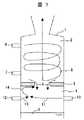
スラグタップの加熱方法及びスラグタップ3の役割について、スラグタップ付近のガスの流動状態を示した図2を用いて、詳細に説明する。 The heating method of the slag tap and the role of the
スラグタップ3の主な役割は、ガス化部2にて、溶融スラグを高温の生成ガス8と分離して排出し、溶融スラグを水槽5の冷却水に供給することである。1500℃以上に達するガス化部2と、水槽5の冷却水には非常に大きな温度差があるため、ガス化部2及びスラグタップ3を高温に保持するためのバッファ空間として、クエンチ部4を設ける。 The main role of the
スラグタップ3から溶融スラグを連続して安定に流下させるためには、スラグタップ3の下面、特にスラグタップ開口部51の下面付近を加熱することと、クエンチ部4内への溶融スラグの飛散防止が必要になる。このため、スラグタップ開口部51の形状を小判型にすることが非常に好ましい。小判型とは、正方形や真円でない矩形の総称であり、楕円、長方形、角丸四角形、瓢箪型などを意味する。 In order to continuously flow molten slag from the
ガス化部2内の旋回流の影響で、スラグタップを下降する下降生成ガス9は、小判型のスラグタップ開口部51の外側、すなわち長辺側から下降する。また、スラグタップ3の上面に溜まった溶融スラグも、スラグタップを下降する下降生成ガス9の流れに同伴され、小判型のスラグタップ開口部51の長辺側から流下する。スラグタップを下降する下降生成ガス9は高温であるため、スラグタップ3を流下する溶融スラグを保温できる。 Due to the influence of the swirling flow in the
次にクエンチ部4において、スラグタップ開口部51の下面で、溶融スラグを重力で落下させる。ここで、溶融スラグを加熱し、かつ溶融スラグの飛散による、クエンチ部4内の側壁への付着・固化を防止しなければならない。小判型のスラグタップ開口部51とすることで、スラグタップを下降する下降生成ガス9の旋回方向の運動エネルギーを減衰させる。これは、旋回方向の速度ベクトルが、スラグタップ開口部51の内壁に衝突することによる。これにより、スラグタップ開口部51の下面にて、溶融スラグがクエンチ部に流入した生成ガス49で振られることにより、クエンチ部4内を飛散することを抑制できる。 Next, in the quench
一方で、クエンチ部に流入した生成ガス49は、旋回方向の運動エネルギーが減衰したため、クエンチ部4内に拡散せず、スラグタップ開口部51の下面付近に滞留しやすくなる。生成ガス49にはCOやH2といった可燃分が含まれているため、スラグタップ開口部51の下面付近に、酸素を含む気体11を供給することで、スラグタップ開口部51の下面付近を局所的に加熱することができる。生成ガス49と、酸素を含む気体11とから発生した燃焼ガスは、スラグタップを上昇する燃焼ガス50となって、スラグタップ開口部51の中央部を上昇し、ガス化部の生成ガス8とともに、炉上方から下流の系統に排出される。On the other hand, the generated
以上のように、小判型の開口部を持つスラグタップ3を用いることで、クエンチ部4へのスラグ飛散を抑制し、スラグタップ開口部51の下面付近を局所的に加熱することができる。 As described above, by using the
ただし、上記の方法を実現するためには、クエンチ部4に投入する酸素を含む気体11を、本実施例のようにスラグタップ開口部51の直下に緩慢に供給することが不可欠になる。その理由は、次の2点である。 However, in order to realize the above method, it is indispensable to slowly supply the
一点目は、スラグタップ開口部51の直下の生成ガス及び溶融スラグの流動状態を乱さないことであり、二点目は、酸素を含む気体11の流量を極力減らすことで、所内動力を低減することである。 The first point is not to disturb the flow state of the product gas and the molten slag immediately below the
すなわち、酸素を含む気体11の噴流を、スラグタップ開口部51に直撃させず、対向する壁面に衝突させて、スラグタップ3の下面に向かう上昇流を形成する。これにより、酸素を含む気体11の噴流を減衰し、スラグタップ開口部51の直下付近にて、クエンチ部に流入した生成ガス49と緩慢混合するようになり、溶融スラグの飛散も抑制される。 That is, the jet of the
また、酸素を含む気体11の噴流の向きを、スラグタップ3と平行にすることで、自身の運動エネルギーと周囲のガスとの間に働くせん断力で、周囲のガスを同伴するため、スラグタップ3の直下の圧力が低下する。これにより、スラグタップ3を下降する下降生成ガス9の流れが促進される。 Moreover, since the direction of the jet of the
酸素を含む気体11の噴流を、スラグタップ開口部51に直撃させた場合には、酸素を含む気体11の噴流で、溶融スラグがクエンチ部4内に飛散するだけでなく、クエンチ部に流入した生成ガス49も乱れ、クエンチ部4内に拡散する。これにより、酸素を含む気体11の投入で着火する領域が大きくなるため、スラグタップ開口部51の下面付近の加熱に必要な、酸素を含む気体11の流量が増加する。 When the jet of the
本実施例では、ガス化部2内に発生させた旋回流を用いて、下降生成ガス9をスラグタップ3からクエンチ部4に下降させる場合について説明した。ここで、下降生成ガス9をスラグタップ3からクエンチ部4に下降させるためには、ガス化部2の外周側の圧力を高くして、クエンチ部4と圧力差を生じさせることがポイントである。従って、ガス化部2とクエンチ部4に圧力差を生じさせる手段を有すれば、本発明は成立する。旋回流以外の方法で圧力差を生じさせる手段としては、例えば、以下の方法がある。 In the present embodiment, the case where the descending product gas 9 is lowered from the
(1)ガス化部2の底部の下段バーナ7を下向きとし、バーナから投入する石炭及びガスの運動エネルギーで、スラグタップ3からクエンチ部4まで貫通する流れを形成する。 (1) With the
(2)クエンチ部4に設置したノズルから、内部のガスを吸引する。これにより、クエンチ部4内の圧力をガス化部2より低くして、ガス化部2内からの下降生成ガス9の下降を促進する。 (2) The internal gas is sucked from the nozzle installed in the quench
本実施例では、スラグタップ保温のために、クエンチ部に複数の加熱バーナを対向させて設置した場合について説明する。図3は、本実施例のガス化炉を示している。 A present Example demonstrates the case where a several heating burner is made to oppose a quench part for slag tap heat insulation. FIG. 3 shows a gasification furnace of this embodiment.
ガス化部2には、上段バーナ6、下段バーナ7が取り付けられており、各バーナより接線方向に石炭、窒素、酸素が投入される。投入された石炭は、ガス化部2においてガス化し、CO及びH2を主成分とする生成ガス8となり、ガス化部2内を旋回しながら下降する。An
下降する生成ガス8の流れは、ガス化部2の底面に設置されたスラグタップ3にて反転し、ガス化部2の中心部を上昇する。一方、生成ガス8の一部は、スラグタップ3を下降し、スラグタップ3直下のクエンチ部4に流入する。ガス化部2での旋回流の影響により、ガス化部2およびスラグタップ3内の圧力分布は、外側で高く、中心側で低い。 The flow of the
従って、スラグタップを下降する下降生成ガス9は、スラグタップ3内の外側を下降する。スラグタップを下降する下降生成ガス9は高温であるため、スラグタップ3を流下する溶融スラグを保温する。 Accordingly, the descending product gas 9 descending the slag tap descends outside the
クエンチ部4には、加熱バーナ10と加熱バーナ12が水平に、対向して設置されている。2本の加熱バーナは、ともに、起動・停止時やガス化炉1を低負荷で運転する際に、助燃バーナとして軽油、酸素、窒素を投入し、スラグタップ3及びガス化部2の下部を加熱する役割を持つ。一方、ガス化炉1を所定の負荷以上で運転する際には、2本の加熱バーナより、それぞれ酸素を含む気体を投入する。ここで、酸素を含む気体とは、例えば酸素と窒素の混合気体である。 In the quench
加熱バーナ10より投入された酸素を含む気体11、及び加熱バーナ12より投入された酸素を含む気体13の噴流は、クエンチ部4内で衝突し、緩慢な上昇流となってスラグタップ3に向かう。 The jets of the
スラグタップ方向に上昇する酸素を含む気体14は、スラグタップ3の下面付近において、スラグタップ3を下降する下降生成ガス9と混合し燃焼する。これは、下降生成ガス9が高温であり、COやH2といった可燃分を含むことによる。The
酸素を含む気体14及び下降生成ガス9による燃焼ガスは、スラグタップ3の中心側を上昇し、ガス化部2内の生成ガス8と混合して、ガス化部2内の中心部を上昇する。 The combustion gas by the
本実施例によれば、既存の助燃バーナを用い、燃料を使用せずに、少ないガス量で、スラグタップ下面付近を局所的に加熱することができる。これにより、エネルギー効率に優れ、スラグタップ3における溶融スラグの安定流下が実現される。 According to the present embodiment, the vicinity of the lower surface of the slag tap can be locally heated with a small amount of gas using an existing auxiliary burner and without using fuel. Thereby, it is excellent in energy efficiency and the stable flow of the molten slag in the
本実施例では、石炭ガス化複合発電プロセスについて説明する。このプロセスでは、実施例2の構造のガス化炉を用い、かつ、加熱バーナから、酸素を含む気体と共に、ガス化炉で発生した生成ガスの一部を供給できるようにした。図4に本実施例の石炭ガス化複合発電プロセスフローを示す。 In this embodiment, a combined coal gasification combined power generation process will be described. In this process, the gasification furnace having the structure of Example 2 was used, and a part of the generated gas generated in the gasification furnace could be supplied from the heating burner together with the gas containing oxygen. FIG. 4 shows a coal gasification combined power generation process flow of this embodiment.
まず、石炭ガス化複合発電のプロセスフローについて説明する。ガス化部2内に投入された有機物はガス化し、CO及びH2を主成分とする生成ガス8となる。生成ガス8は、ガス化炉1の頂部から熱回収部15を経て冷却され、脱塵装置16にて脱塵され、塩素除去装置17にて塩素が除去される。さらに、脱硫装置18にて脱硫されて、生成ガス8中の不純物が除去される。First, the process flow of coal gasification combined cycle power generation will be described. The organic substance thrown into the
脱硫装置18を出た生成ガスは、発電用の生成ガス20として、燃焼器21に供給される。燃焼器21では、圧縮機22からの空気が供給され、発電用の生成ガス20と混合・燃焼する。燃焼器21の排ガスは、ガスタービン23を駆動し、ボイラ25で冷却され、煙突27から系外に出される。ここで、ボイラ25では、排ガスの熱で蒸気26が加熱され、蒸気タービン24を駆動する。 The product gas that has exited the
一方、脱硫装置18では、硫黄分を石膏として回収するものの、微量の硫黄分(H2S等)を含む排ガス19も排出する。この排ガス19は、燃焼器52で完全燃焼させた後、煙突27に供給される。On the other hand, the
石炭ガス化複合発電プロセスでは、ガス化炉1を加圧状態で運転する。この場合、空気46をガスタービン23で駆動する圧縮機22で昇圧し、空気分離設備29にて酸素30及び窒素31を取り出し、独立した系統でガス化炉1に供給する。この系統から、クエンチ部4に設置した加熱バーナ10及び加熱バーナ12に酸素30及び窒素31が供給される。 In the coal gasification combined power generation process, the gasification furnace 1 is operated in a pressurized state. In this case, the
ここで、非常用として、加熱バーナ10及び加熱バーナ12には、上述の脱硫装置18を出た生成ガスの一部を、加熱バーナ供給用の生成ガス28として供給する系統を備えておくと良い。本系統の使用方法について、以下に説明する。 Here, as an emergency, the
スラグタップ3において、溶融スラグの冷却・固化により、スラグタップ孔の面積が縮小すると、一般に、ガス化部2よりスラグタップを下降する下降生成ガス9の流量は減少する。これは、実施例2でも述べたように、旋回流の影響でガス化部2の外側の圧力が高いため、スラグタップを下降する下降生成ガス9は、スラグタップ3の外側から流入することによる。 In the
この場合、クエンチ部の加熱バーナ10及び加熱バーナ12から投入する酸素30の流量を増加させても、スラグタップ3の下面を保温できない。これは、スラグタップを下降する下降生成ガス9の流量が減少するため、クエンチ部4内のスラグタップ3の下面付近における可燃分が少ないためである。 In this case, the lower surface of the
スラグタップ3の下面を保温するためには、可燃分を追加で投入する必要がある。そこで、加熱バーナ供給用の生成ガス28を用いる。加熱バーナ供給用の生成ガス28は、300℃以下で供給されており、加熱バーナから供給された酸素を含む気体11、及び加熱バーナ12から供給された酸素を含む気体13に同伴され、クエンチ部4内で衝突・混合する。スラグタップ方向に上昇する酸素を含む気体14は、可燃分である加熱バーナ供給用の生成ガス28を同伴して、スラグタップ3直下に上昇する。上部のガス化部2からの伝熱により、クエンチ部4内の温度は、スラグタップ3に近づくほど高くなる。これにより、加熱バーナ供給用の生成ガス28は、スラグタップ3下面付近で燃焼するため、燃料を用いずにスラグタップを保温できる。 In order to keep the bottom surface of the
加熱バーナ供給用の生成ガス28を用いると、プラント効率は低下する。従って、定常運転中は、加熱バーナから酸素30及び窒素31のみを投入して、スラグタップ3下面を保温する運転方法が良い。溶融スラグの冷却・固化によりスラグタップ3の孔が閉塞傾向にある場合、及びスラグタップ3下部の付着スラグを焼ききる場合といった非常時に、加熱バーナ供給用の生成ガス28を用いると良い。 When the
石炭ガス化複合発電プロセスの別の実施形態について、図5を用いて説明する。図5では、加熱バーナ10と加熱バーナ12から、酸素富化した空気、及びガス化炉で発生した生成ガスの一部を供給できるようにした。 Another embodiment of the combined coal gasification combined power generation process will be described with reference to FIG. In FIG. 5, oxygen-enriched air and a part of the product gas generated in the gasification furnace can be supplied from the
図5に示す石炭ガス化複合発電プロセスにおいて、空気46は圧縮機22で昇圧され、加熱バーナに供給する空気47の系統、及び空気分離設備29にそれぞれ供給される。圧縮機22では、空気46を最大2MPa程度までしか昇圧できないため、空気46を2MPa以上に昇圧する場合には、昇圧機48を追設する。 In the combined coal gasification combined power generation process shown in FIG. 5, the
空気分離設備29では、酸素30を取り出し、加熱バーナに供給する空気47の系統に混合する。これにより、加熱バーナに供給する空気47を、酸素富化することができる。 In the
尚、本実施例では、加熱バーナに供給する空気47をガスタービン23の動力で駆動する圧縮機22で抽気したガス化設備について説明した。しかし、加熱バーナに供給する空気47は、前記の圧縮機22ではなく、ガスタービン23とは別個に運転する新たなコンプレッサから抽気しても良い。 In this embodiment, the gasification facility in which the
また、本実施例では、酸素製造装置として、空気分離設備29を用いたガス化設備について説明したが、ボンベ等から供給した酸素を用いても構わない。 Moreover, although the gasification installation using the
本実施例では、ガス化炉のクエンチ部に設置する加熱バーナを、水平よりも上向きに角度をつけて設置した場合について説明する。図6は、本実施例のガス化炉の断面図を示す。 A present Example demonstrates the case where the heating burner installed in the quenching part of a gasification furnace is installed at an angle upward from the horizontal. FIG. 6 shows a sectional view of the gasification furnace of this example.
図6では、クエンチ部4に、加熱バーナ10と加熱バーナ12が、水平に対して上向きに、対向して設置されている。バーナの水平に対する設置角度は、0〜45度程度が望ましい。これは、両バーナからの噴流をスラグタップ3の直下で衝突させるためである。 In FIG. 6, a
ガス化炉1を所定の負荷以上で運転する際には、2本の加熱バーナより、それぞれ酸素を含む気体を投入する。ここで、酸素を含む気体とは、例えば酸素と窒素の混合気体である。 When the gasification furnace 1 is operated at a predetermined load or more, gas containing oxygen is introduced from the two heating burners. Here, the gas containing oxygen is, for example, a mixed gas of oxygen and nitrogen.
加熱バーナ10より投入された酸素を含む気体11、及び加熱バーナ12より投入された酸素を含む気体13の噴流は、スラグタップ3の直下で衝突して減衰し、緩慢な上昇流となってスラグタップ3に向かう。 The jets of the
本実施例のように、加熱バーナの噴流をスラグタップ3の直下で衝突させると、スラグタップ3直下の流れが乱れる。これにより、スラグタップ方向に上昇する酸素を含む気体14は、スラグタップ3の下面付近において、スラグタップを下降する下降生成ガス9と混合しやすくなる。従って、スラグタップ3直下における下降生成ガス9の燃焼が促進され、加熱バーナから供給する酸素量を低減できる。 If the jet of the heating burner is caused to collide directly under the
本実施例では、クエンチ部の左右に設置された加熱バーナに投入するガスの運動量を独立に変化させて不均一とした場合について説明する。図7に本実施例のガス化炉を示す。 In the present embodiment, a case will be described in which the momentum of the gas introduced into the heating burners installed on the left and right of the quenching section is changed independently to make it non-uniform. FIG. 7 shows the gasification furnace of this example.
加熱バーナ10及び加熱バーナ12に投入するガスの運動量を独立に変化させるには、たとえば、バーナ口径を左右で変える、或いは左右のバーナから投入するガスの流量を独立に変えることが望ましい。上記のうち一つを用いてもよいし、両方を組み合わせても構わない。 In order to independently change the momentum of the gas supplied to the
ガス化炉1を所定の負荷以上で運転する際には、加熱バーナ10と加熱バーナ12より酸素を含む気体を投入する。ここで、酸素を含む気体とは、例えば酸素と窒素の混合気体、酸素富化した空気である。 When the gasification furnace 1 is operated at a predetermined load or higher, a gas containing oxygen is supplied from the
本実施例では、加熱バーナ10より投入された酸素を含む気体11の噴流の持つ運動量が、加熱バーナ12より投入された酸素を含む気体13の噴流の持つ運動量よりも強い場合について説明する。 In this embodiment, a case will be described in which the momentum of the jet of the
加熱バーナ10より投入された酸素を含む気体11の噴流は、加熱バーナ12より投入された酸素を含む気体13の噴流と衝突するものの、自身の運動量の強さから、クエンチ部4の壁面近傍に到達し、スラグタップ3下面に向かう渦を形成する。ここで、本方式は、加熱バーナ10からの噴流が、クエンチ部4の壁面への衝突を抑えるため、壁面衝突時の噴流の上下への分散抑制や、壁面の保護にも有効である。 Although the jet of the
渦状でスラグタップ方向に上昇する酸素を含む気体14は、スラグタップ3の下面付近において、スラグタップを下降する下降生成ガス9と混合し燃焼する。これは、下降生成ガス9が高温であり、COやH2といった可燃分を含むことによる。The
また、酸素を含む気体11の噴流は、直進する際に、自身のせん断力で周囲のガスを同伴するため、スラグタップ3の直下の圧力が低下する。これにより、スラグタップを下降する下降生成ガス9の流れが促進される。 Moreover, since the jet of the
本方式は、せん断力によるクエンチ部4への生成ガス流入促進、渦流を用いたスラグタップ直下での加熱バーナから投入された酸素と生成ガスの混合促進、2つの対向噴流の衝突による壁面保護といった観点から、燃料を用いずにスラグタップ3下面を保温する最良の方法である。 This method promotes the flow of product gas into the
本実施例では、クエンチ部の加熱バーナ10,12とスラグタップの間に、対向する2本の加熱ノズルを追設した場合について説明する。図8は、本実施例のガス化炉を示す。 A present Example demonstrates the case where two opposing heating nozzles are additionally installed between the
クエンチ部4において、対向する加熱バーナ10,12と、スラグタップ3の間に、2本の加熱ノズル32,33を対向させて設置する。 In the quench
加熱バーナ10,12と加熱ノズル32,33に供給するガスは、酸素、窒素、ガス化炉1で発生した生成ガス8である。ガス化炉1の定常運転時は、加熱バーナ10及び加熱バーナ12のみを用い、非常時に加熱ノズル32及び加熱ノズル33を用いると良い。以下、加熱ノズルを用いたスラグタップ3下面の保温方法について説明する。 The gas supplied to the
ここで、非常時とは、ガス化部2内での旋回流の流速低下、溶融スラグの冷却・固化によるスラグタップ3の孔面積の縮小などにより、ガス化部2よりスラグタップを下降する下降生成ガス9の流量が減少して、溶融スラグを安定排出できない場合である。 Here, emergency means that the slag tap descends from the
この場合に、加熱ノズル32,33を用いて、スラグタップ下面付近を局所的に加熱する。加熱ノズル32及び加熱ノズル33をクエンチ部4内に挿入し、ノズル先端をスラグタップ3の直下付近に設置する。加熱ノズル32及び加熱ノズル33から、酸素及びガス化部で発生した生成ガスを投入することで、スラグタップ3の下面付近のみを加熱する。 In this case, the vicinity of the lower surface of the slag tap is locally heated using the
尚、加熱ノズル32,33の保護の観点から、これらのノズルをクエンチ部4内に挿入するのは非常時のみとし、定常運転時は、クエンチ部の外に抜き出し、休止させておくのが良い。 From the viewpoint of protecting the
本実施例では、石炭ガス化発電プラントにおいて、クエンチ部における加熱バーナの制御装置を含む石炭ガス化発電プラントについて、図9を参照して説明する。 A present Example demonstrates a coal gasification power plant in FIG. 9 with reference to FIG. 9 about the coal gasification power plant including the control apparatus of the heating burner in a quench part.
本実施例において、スラグタップ3の保温状態及び溶融スラグの流下状態は、以下に示す5種類のデータを制御装置40に取り込み、監視する。 In the present embodiment, the heat retention state of the
5種類のデータは、スラグタップ内ガス温度、クエンチ部内ガス温度、スラグタップ差圧、溶融スラグ流下の画像、およびスラグ重量である。 The five types of data are slag tap gas temperature, quench portion gas temperature, slag tap differential pressure, molten slag flow image, and slag weight.
スラグタップ内ガス温度は、スラグタップ温度計42で計測する。温度計測位置が溶融スラグに埋まった場合でも、ガス化部2に投入した無機物の軟化点以上の温度が保持されるようにする。 The gas temperature in the slag tap is measured by the
クエンチ部内ガス温度は、クエンチ部温度計43で計測する。温度計の設置位置は、スラグタップ3の孔部下面に近づける方が良い。クエンチ部温度計43の温度が、スラグタップ3下面に溶融スラグが付着・固化しない温度になるように、ガス化部2に投入した無機物の軟化点以上を保持する。 The quench portion gas temperature is measured by the
クエンチ部温度計43を複数設けて、スラグタップ下面の温度だけでなく、壁面近傍のガス温度も計測することは望ましい。壁面近傍のクエンチ部温度計43の温度が、ガス化部2に投入した無機物の軟化点以下又は側壁材料の許容温度以下となるようにすることにより、壁面近傍に飛散した溶融スラグの壁面への付着を防止して、炉壁の溶損を防止できる。 It is desirable to provide a plurality of quench
スラグタップ差圧は、ガス化部2とクエンチ部4の差圧を、差圧計44で計測することにより計測される。スラグタップが溶融スラグ等で閉塞すると、差圧計44の差圧が上昇する。従って、この差圧を所定値以下に保持されるようにする。 The slag tap differential pressure is measured by measuring the differential pressure between the
溶融スラグ流下の画像は、クエンチ部4内に監視カメラ45を設置して撮影する。スラグタップ3又はクエンチ部4内を流下する溶融スラグの画像を監視して、定常運転時のスラグの流下状態から変化がないか否かを監視する。 An image under the molten slag flow is taken by installing a
スラグ重量は、スラグ重量計測器41により、単位時間あたりのスラグ回収量を計測する。ガス化部2に投入した無機物の重量に対し、所定の割合分をスラグとして回収できているか否かを監視する。 The slag weight is measured by the slag
定常運転時で、上記の5項目のいずれかで異常を検知した場合には、加熱バーナの運用条件を以下の手順で変更し、加熱バーナ10,12に投入する酸素、窒素、ガス化炉生成ガスの流量を制御して、ラグタップ3下面の加熱及び溶融スラグの流下を促進する。尚、2本の加熱バーナのうち、1本のみ運用条件を変更しても良いし、2本とも運用条件を変更しても構わない。制御は、生成ガス流量制御バルブ34,35と、酸素流量制御バルブ36,37と、窒素流量制御バルブ38,39の開度を調節することによって行われる。 If abnormalities are detected in any of the above five items during steady operation, the operating conditions of the heating burner are changed according to the following procedure, and oxygen, nitrogen, and gasifier generated in the
手順1:酸素30及び窒素31の流量を増加させる。 Procedure 1: Increase
手順2:酸素30の流量のみ増加させ、加熱バーナから投入する気体の酸素濃度を高くする。本手順では、加熱バーナ保護のため、加熱バーナから投入する気体の酸素濃度に上限値を設けることが望ましい。 Procedure 2: Only the flow rate of
手順3:加熱バーナに、加熱バーナ供給用の生成ガス28を供給する。本手順では、クエンチ部温度計43を複数設置することで、火炎の位置の把握、クエンチ部4の側壁及び加熱バーナ端面の保護にも注意する必要がある。また、発電効率を高める観点から、本手順は非定常時のみの運用とすることが望ましい。 Procedure 3: Supply the
1…ガス化炉、2…ガス化部、3…スラグタップ、4…クエンチ部、5…水槽、6…上段バーナ、7…下段バーナ、8…生成ガス、9…下降生成ガス、10…加熱バーナ、11…酸素を含む気体、12…加熱バーナ、13…酸素を含む気体、14…酸素を含む気体、15…熱回収部、16…脱塵装置、17…塩素除去装置、18…脱硫装置、19…排ガス、20…発電用の生成ガス、21…燃焼器、22…圧縮機、23…ガスタービン、24…蒸気タービン、25…ボイラ、26…蒸気、27…煙突、28…加熱バーナ供給用の生成ガス、29…空気分離設備、30…酸素、31…窒素、32…加熱ノズル、33…加熱ノズル、34…生成ガス流量制御バルブ、35…生成ガス流量制御バルブ、36…酸素流量制御バルブ、37…酸素流量制御バルブ、38…窒素流量制御バルブ、39…窒素流量制御バルブ、40…制御装置、41…スラグ重量計測器、42…スラグタップ温度計、43…クエンチ部温度計、44…差圧計、45…監視カメラ、46…空気、47…加熱バーナに供給する空気、48…昇圧機、49…クエンチ部に流入した生成ガス、50…スラグタップを上昇する燃焼ガス、51…スラグタップ開口部、52…燃焼器。 DESCRIPTION OF SYMBOLS 1 ... Gasification furnace, 2 ... Gasification part, 3 ... Slag tap, 4 ... Quench part, 5 ... Water tank, 6 ... Upper burner, 7 ... Lower burner, 8 ... Product gas, 9 ... Falling product gas, 10 ... Heating Burner, 11 ... gas containing oxygen, 12 ... heating burner, 13 ... gas containing oxygen, 14 ... gas containing oxygen, 15 ... heat recovery section, 16 ... dust removal device, 17 ... chlorine removal device, 18 ... desulfurization device , 19 ... exhaust gas, 20 ... generated gas for power generation, 21 ... combustor, 22 ... compressor, 23 ... gas turbine, 24 ... steam turbine, 25 ... boiler, 26 ... steam, 27 ... chimney, 28 ... heating burner supply Product gas, 29 ... Air separation equipment, 30 ... Oxygen, 31 ... Nitrogen, 32 ... Heating nozzle, 33 ... Heating nozzle, 34 ... Product gas flow control valve, 35 ... Product gas flow control valve, 36 ... Oxygen flow control Valve, 37 ... Oxygen flow control Valve: 38 ... Nitrogen flow rate control valve, 39 ... Nitrogen flow rate control valve, 40 ... Control device, 41 ... Slag weight measuring device, 42 ... Slag tap thermometer, 43 ... Quench thermometer, 44 ... Differential pressure gauge, 45 ... Monitoring Camera, 46 ... Air, 47 ... Air supplied to heating burner, 48 ... Pressure booster, 49 ... Production gas flowing into quenching part, 50 ... Combustion gas rising slag tap, 51 ... Slag tap opening, 52 ... Combustion vessel.
Claims (12)
Translated fromJapanese前記クエンチ部の内部で、ノズルから噴出した酸素を含む気体の噴流を、前記ノズルに対向する前記クエンチ部の壁面に衝突させることを特徴とするガス化炉の運転方法。Gasification part which gasifies organic substance and makes inorganic substance molten slag, and is located at the bottom of the gasification part, and flows down the molten slag together with a part of the generated gas generated by gasification of organic substance in the gasification part In the operation method of the gasification furnace comprising the slag tap, the quenching part at the lower part of the slag tap, and the water tank at the lower part of the quenching part,
An operation method of a gasification furnace, wherein a jet of gas containing oxygen ejected from a nozzle is caused to collide with a wall surface of the quenching portion facing the nozzle inside the quenching portion.
前記クエンチ部の内部で、複数のノズルから酸素を含む気体の噴流を衝突させるように噴出させ、前記酸素を含む気体の噴流の運動量を異ならしめることを特徴とするガス化炉の運転方法。Gasification part which gasifies organic substance and makes inorganic substance molten slag, and is located at the bottom of the gasification part, and flows down the molten slag together with a part of the generated gas generated by gasification of organic substance in the gasification part In the operation method of the gasification furnace comprising the slag tap, the quenching part at the lower part of the slag tap, and the water tank at the lower part of the quenching part,
An operation method of a gasification furnace, wherein jets of gas containing oxygen are ejected from a plurality of nozzles so as to collide with each other, and the momentum of the jet of gas containing oxygen is made different.
Priority Applications (1)
| Application Number | Priority Date | Filing Date | Title |
|---|---|---|---|
| JP2007114257AJP5139714B2 (en) | 2007-04-24 | 2007-04-24 | Gasifier and gasifier |
Applications Claiming Priority (1)
| Application Number | Priority Date | Filing Date | Title |
|---|---|---|---|
| JP2007114257AJP5139714B2 (en) | 2007-04-24 | 2007-04-24 | Gasifier and gasifier |
Related Child Applications (1)
| Application Number | Title | Priority Date | Filing Date |
|---|---|---|---|
| JP2012223903ADivisionJP2013007059A (en) | 2012-10-09 | 2012-10-09 | Gasification furnace, gasification power generation plant, gasification apparatus and method for operating gasification furnace |
Publications (2)
| Publication Number | Publication Date |
|---|---|
| JP2008266516Atrue JP2008266516A (en) | 2008-11-06 |
| JP5139714B2 JP5139714B2 (en) | 2013-02-06 |
Family
ID=40046448
Family Applications (1)
| Application Number | Title | Priority Date | Filing Date |
|---|---|---|---|
| JP2007114257AActiveJP5139714B2 (en) | 2007-04-24 | 2007-04-24 | Gasifier and gasifier |
Country Status (1)
| Country | Link |
|---|---|
| JP (1) | JP5139714B2 (en) |
Cited By (6)
| Publication number | Priority date | Publication date | Assignee | Title |
|---|---|---|---|---|
| JP2010163499A (en)* | 2009-01-13 | 2010-07-29 | Electric Power Dev Co Ltd | Method for operating entrained-bed gasification furnace |
| JP2011137144A (en)* | 2009-12-01 | 2011-07-14 | Electric Power Dev Co Ltd | Gasification furnace, gasification power generation plant, method for operating gasification furnace and method for operating gasification power generation plant |
| JP2012062376A (en)* | 2010-09-15 | 2012-03-29 | Babcock Hitachi Kk | Gasification furnace, operation method of the same, and coal gasification compound power plant |
| JP2013177482A (en)* | 2012-02-28 | 2013-09-09 | Babcock Hitachi Kk | Gasification furnace and method of detecting slag tap clogging of the same |
| CN105733686A (en)* | 2016-05-05 | 2016-07-06 | 神华集团有限责任公司 | Ring-type impact gasifier |
| CN115772423A (en)* | 2022-11-03 | 2023-03-10 | 宁夏大学 | A melting gasification system and method for gasification treatment of carbon-containing hazardous waste |
Citations (7)
| Publication number | Priority date | Publication date | Assignee | Title |
|---|---|---|---|---|
| JPS6088091A (en)* | 1983-10-21 | 1985-05-17 | Hitachi Ltd | Method of operating a spouted bed coal gasifier and its device |
| JPH02195102A (en)* | 1989-01-24 | 1990-08-01 | Babcock Hitachi Kk | Starting and hot banking system of coal gassification furnace |
| JPH08134472A (en)* | 1994-11-10 | 1996-05-28 | Babcock Hitachi Kk | Entrained-bed gasifier |
| JPH0967582A (en)* | 1995-08-31 | 1997-03-11 | Hitachi Ltd | Method and apparatus for producing hydrogen / carbon monoxide mixed gas |
| JPH0987639A (en)* | 1995-09-22 | 1997-03-31 | Hitachi Ltd | Slag tap structure and gasifier using this slag tap |
| JP2004101083A (en)* | 2002-09-10 | 2004-04-02 | Mitsubishi Heavy Ind Ltd | Gasification furnace and burner |
| JP2004099760A (en)* | 2002-09-10 | 2004-04-02 | Mitsubishi Heavy Ind Ltd | Method for operating gasification furnace, and gasification furnace |
- 2007
- 2007-04-24JPJP2007114257Apatent/JP5139714B2/enactiveActive
Patent Citations (7)
| Publication number | Priority date | Publication date | Assignee | Title |
|---|---|---|---|---|
| JPS6088091A (en)* | 1983-10-21 | 1985-05-17 | Hitachi Ltd | Method of operating a spouted bed coal gasifier and its device |
| JPH02195102A (en)* | 1989-01-24 | 1990-08-01 | Babcock Hitachi Kk | Starting and hot banking system of coal gassification furnace |
| JPH08134472A (en)* | 1994-11-10 | 1996-05-28 | Babcock Hitachi Kk | Entrained-bed gasifier |
| JPH0967582A (en)* | 1995-08-31 | 1997-03-11 | Hitachi Ltd | Method and apparatus for producing hydrogen / carbon monoxide mixed gas |
| JPH0987639A (en)* | 1995-09-22 | 1997-03-31 | Hitachi Ltd | Slag tap structure and gasifier using this slag tap |
| JP2004101083A (en)* | 2002-09-10 | 2004-04-02 | Mitsubishi Heavy Ind Ltd | Gasification furnace and burner |
| JP2004099760A (en)* | 2002-09-10 | 2004-04-02 | Mitsubishi Heavy Ind Ltd | Method for operating gasification furnace, and gasification furnace |
Cited By (7)
| Publication number | Priority date | Publication date | Assignee | Title |
|---|---|---|---|---|
| JP2010163499A (en)* | 2009-01-13 | 2010-07-29 | Electric Power Dev Co Ltd | Method for operating entrained-bed gasification furnace |
| JP2011137144A (en)* | 2009-12-01 | 2011-07-14 | Electric Power Dev Co Ltd | Gasification furnace, gasification power generation plant, method for operating gasification furnace and method for operating gasification power generation plant |
| JP2012062376A (en)* | 2010-09-15 | 2012-03-29 | Babcock Hitachi Kk | Gasification furnace, operation method of the same, and coal gasification compound power plant |
| JP2013177482A (en)* | 2012-02-28 | 2013-09-09 | Babcock Hitachi Kk | Gasification furnace and method of detecting slag tap clogging of the same |
| CN105733686A (en)* | 2016-05-05 | 2016-07-06 | 神华集团有限责任公司 | Ring-type impact gasifier |
| CN105733686B (en)* | 2016-05-05 | 2019-04-02 | 神华集团有限责任公司 | Ring type collision type gasification furnace |
| CN115772423A (en)* | 2022-11-03 | 2023-03-10 | 宁夏大学 | A melting gasification system and method for gasification treatment of carbon-containing hazardous waste |
Also Published As
| Publication number | Publication date |
|---|---|
| JP5139714B2 (en) | 2013-02-06 |
Similar Documents
| Publication | Publication Date | Title |
|---|---|---|
| US8197564B2 (en) | Method and apparatus for cooling syngas within a gasifier system | |
| JP5139714B2 (en) | Gasifier and gasifier | |
| EP2684939B1 (en) | System and method for protecting gasifier quench ring | |
| CA2710732C (en) | Method and apparatus to produce synthetic gas | |
| CN205382134U (en) | Coal slurry gasification equipment | |
| JP5812597B2 (en) | Gasification furnace, gasification power plant, operation method of gasification furnace, and operation method of gasification power plant | |
| JP5812588B2 (en) | Gasification furnace, operation method of gasification furnace, and coal gasification combined power plant | |
| JP5617531B2 (en) | Combustion method of low calorific value gas by combustion burner and blast furnace operation method | |
| EP2873741B1 (en) | Blast furnace operating method and tube bundle-type lance | |
| EP2500643B1 (en) | Injector tip | |
| KR20160047583A (en) | Top submerged injection lance for enhanced submerged combustion | |
| JP2013007059A (en) | Gasification furnace, gasification power generation plant, gasification apparatus and method for operating gasification furnace | |
| KR101314443B1 (en) | Blast furnace operation method, low-calorific-value gas combustion method for same, and blast furnace equipment | |
| CN104053792A (en) | Starting a smelting process | |
| BR112014013493B1 (en) | METHOD OF INITIATING A BATH BASED REDUCTION PROCESS OF FUSED MATERIAL TO REDUCE A METAL-FEED FEEDING MATERIAL IN A REDUCING APPARATUS | |
| CA2702576C (en) | Method and system for sealing an annulus | |
| JP5893956B2 (en) | Gasification furnace and slag tap blockage detection method thereof | |
| KR20130095838A (en) | Method for the pyrometallurigical treatment of metals, molten metals, and/or slags | |
| JP2010254727A (en) | Gas bed gasification furnace and operation method thereof | |
| JP5392229B2 (en) | Combustion method of low calorific value gas by combustion burner | |
| JP2011195781A (en) | Gasification furnace | |
| JP5044317B2 (en) | Combustion chamber and combustion method for waste gasification and melting equipment | |
| JP2009019125A (en) | Gasification method and apparatus | |
| JP2012215352A (en) | Gasifying melting furnace | |
| KR102787651B1 (en) | Direct smelting process through complete combustion |
Legal Events
| Date | Code | Title | Description |
|---|---|---|---|
| A621 | Written request for application examination | Free format text:JAPANESE INTERMEDIATE CODE: A621 Effective date:20100209 | |
| A977 | Report on retrieval | Free format text:JAPANESE INTERMEDIATE CODE: A971007 Effective date:20120425 | |
| A131 | Notification of reasons for refusal | Free format text:JAPANESE INTERMEDIATE CODE: A131 Effective date:20120508 | |
| A521 | Request for written amendment filed | Free format text:JAPANESE INTERMEDIATE CODE: A523 Effective date:20120622 | |
| A02 | Decision of refusal | Free format text:JAPANESE INTERMEDIATE CODE: A02 Effective date:20120710 | |
| A521 | Request for written amendment filed | Free format text:JAPANESE INTERMEDIATE CODE: A523 Effective date:20121009 | |
| A911 | Transfer to examiner for re-examination before appeal (zenchi) | Free format text:JAPANESE INTERMEDIATE CODE: A911 Effective date:20121017 | |
| TRDD | Decision of grant or rejection written | ||
| A01 | Written decision to grant a patent or to grant a registration (utility model) | Free format text:JAPANESE INTERMEDIATE CODE: A01 Effective date:20121106 | |
| A01 | Written decision to grant a patent or to grant a registration (utility model) | Free format text:JAPANESE INTERMEDIATE CODE: A01 | |
| A61 | First payment of annual fees (during grant procedure) | Free format text:JAPANESE INTERMEDIATE CODE: A61 Effective date:20121116 | |
| R150 | Certificate of patent or registration of utility model | Free format text:JAPANESE INTERMEDIATE CODE: R150 Ref document number:5139714 Country of ref document:JP Free format text:JAPANESE INTERMEDIATE CODE: R150 | |
| FPAY | Renewal fee payment (event date is renewal date of database) | Free format text:PAYMENT UNTIL: 20151122 Year of fee payment:3 | |
| S111 | Request for change of ownership or part of ownership | Free format text:JAPANESE INTERMEDIATE CODE: R313115 | |
| R350 | Written notification of registration of transfer | Free format text:JAPANESE INTERMEDIATE CODE: R350 | |
| R250 | Receipt of annual fees | Free format text:JAPANESE INTERMEDIATE CODE: R250 | |
| R250 | Receipt of annual fees | Free format text:JAPANESE INTERMEDIATE CODE: R250 | |
| S533 | Written request for registration of change of name | Free format text:JAPANESE INTERMEDIATE CODE: R313533 | |
| R350 | Written notification of registration of transfer | Free format text:JAPANESE INTERMEDIATE CODE: R350 | |
| R250 | Receipt of annual fees | Free format text:JAPANESE INTERMEDIATE CODE: R250 | |
| R250 | Receipt of annual fees | Free format text:JAPANESE INTERMEDIATE CODE: R250 | |
| R250 | Receipt of annual fees | Free format text:JAPANESE INTERMEDIATE CODE: R250 | |
| R250 | Receipt of annual fees | Free format text:JAPANESE INTERMEDIATE CODE: R250 |