JP2008265278A - Label tape, label tape cartridge, label making device - Google Patents
Label tape, label tape cartridge, label making deviceDownload PDFInfo
- Publication number
- JP2008265278A JP2008265278AJP2007291228AJP2007291228AJP2008265278AJP 2008265278 AJP2008265278 AJP 2008265278AJP 2007291228 AJP2007291228 AJP 2007291228AJP 2007291228 AJP2007291228 AJP 2007291228AJP 2008265278 AJP2008265278 AJP 2008265278A
- Authority
- JP
- Japan
- Prior art keywords
- label
- tape
- mark
- detected
- tag
- Prior art date
- Legal status (The legal status is an assumption and is not a legal conclusion. Google has not performed a legal analysis and makes no representation as to the accuracy of the status listed.)
- Pending
Links
- 238000007639printingMethods0.000claimsabstractdescription124
- 238000001514detection methodMethods0.000claimsabstractdescription112
- 238000004804windingMethods0.000claimsabstractdescription5
- 238000005520cutting processMethods0.000claimsdescription169
- 238000004891communicationMethods0.000claimsdescription75
- 238000004519manufacturing processMethods0.000claimsdescription44
- 239000012790adhesive layerSubstances0.000claimsdescription25
- 239000010410layerSubstances0.000claimsdescription25
- 239000000463materialSubstances0.000claimsdescription25
- 238000009434installationMethods0.000claimsdescription12
- 239000003086colorantSubstances0.000claimsdescription3
- 239000013039cover filmSubstances0.000abstractdescription36
- 239000005022packaging materialSubstances0.000description229
- 239000011295pitchSubstances0.000description198
- 238000000034methodMethods0.000description130
- 230000008569processEffects0.000description73
- 230000004048modificationEffects0.000description36
- 238000012986modificationMethods0.000description36
- 230000007246mechanismEffects0.000description27
- 230000005540biological transmissionEffects0.000description20
- 230000006870functionEffects0.000description16
- 238000010586diagramMethods0.000description15
- 238000012545processingMethods0.000description15
- 239000010408filmSubstances0.000description14
- 230000004044responseEffects0.000description12
- 238000007599dischargingMethods0.000description10
- 238000003860storageMethods0.000description10
- 238000002360preparation methodMethods0.000description9
- 230000000694effectsEffects0.000description7
- 238000012546transferMethods0.000description7
- 238000003825pressingMethods0.000description5
- 238000011144upstream manufacturingMethods0.000description5
- 239000000853adhesiveSubstances0.000description4
- 230000001070adhesive effectEffects0.000description4
- 239000000284extractSubstances0.000description3
- 239000000758substrateSubstances0.000description3
- 239000002699waste materialSubstances0.000description3
- 230000009471actionEffects0.000description2
- 230000015572biosynthetic processEffects0.000description2
- 230000008859changeEffects0.000description2
- 230000005674electromagnetic inductionEffects0.000description2
- 238000000605extractionMethods0.000description2
- 238000010438heat treatmentMethods0.000description2
- 230000003287optical effectEffects0.000description2
- 230000000149penetrating effectEffects0.000description2
- 229920000139polyethylene terephthalatePolymers0.000description2
- 239000005020polyethylene terephthalateSubstances0.000description2
- PCTMTFRHKVHKIS-BMFZQQSSSA-N(1s,3r,4e,6e,8e,10e,12e,14e,16e,18s,19r,20r,21s,25r,27r,30r,31r,33s,35r,37s,38r)-3-[(2r,3s,4s,5s,6r)-4-amino-3,5-dihydroxy-6-methyloxan-2-yl]oxy-19,25,27,30,31,33,35,37-octahydroxy-18,20,21-trimethyl-23-oxo-22,39-dioxabicyclo[33.3.1]nonatriaconta-4,6,8,10Chemical compoundC1C=C2C[C@@H](OS(O)(=O)=O)CC[C@]2(C)[C@@H]2[C@@H]1[C@@H]1CC[C@H]([C@H](C)CCCC(C)C)[C@@]1(C)CC2.O[C@H]1[C@@H](N)[C@H](O)[C@@H](C)O[C@H]1O[C@H]1/C=C/C=C/C=C/C=C/C=C/C=C/C=C/[C@H](C)[C@@H](O)[C@@H](C)[C@H](C)OC(=O)C[C@H](O)C[C@H](O)CC[C@@H](O)[C@H](O)C[C@H](O)C[C@](O)(C[C@H](O)[C@H]2C(O)=O)O[C@H]2C1PCTMTFRHKVHKIS-BMFZQQSSSA-N0.000description1
- 210000000038chestAnatomy0.000description1
- 238000007796conventional methodMethods0.000description1
- 230000008878couplingEffects0.000description1
- 238000010168coupling processMethods0.000description1
- 238000005859coupling reactionMethods0.000description1
- 238000002788crimpingMethods0.000description1
- 125000004122cyclic groupChemical group0.000description1
- 230000007547defectEffects0.000description1
- 230000008676importEffects0.000description1
- 238000003780insertionMethods0.000description1
- 230000037431insertionEffects0.000description1
- 239000002184metalSubstances0.000description1
- -1polyethylene terephthalatePolymers0.000description1
- 239000011347resinSubstances0.000description1
- 229920005989resinPolymers0.000description1
- 230000000717retained effectEffects0.000description1
- 238000000926separation methodMethods0.000description1
- 230000009466transformationEffects0.000description1
Images


Classifications
- B—PERFORMING OPERATIONS; TRANSPORTING
- B41—PRINTING; LINING MACHINES; TYPEWRITERS; STAMPS
- B41J—TYPEWRITERS; SELECTIVE PRINTING MECHANISMS, i.e. MECHANISMS PRINTING OTHERWISE THAN FROM A FORME; CORRECTION OF TYPOGRAPHICAL ERRORS
- B41J3/00—Typewriters or selective printing or marking mechanisms characterised by the purpose for which they are constructed
- B41J3/407—Typewriters or selective printing or marking mechanisms characterised by the purpose for which they are constructed for marking on special material
- B41J3/4075—Tape printers; Label printers
- B—PERFORMING OPERATIONS; TRANSPORTING
- B41—PRINTING; LINING MACHINES; TYPEWRITERS; STAMPS
- B41J—TYPEWRITERS; SELECTIVE PRINTING MECHANISMS, i.e. MECHANISMS PRINTING OTHERWISE THAN FROM A FORME; CORRECTION OF TYPOGRAPHICAL ERRORS
- B41J11/00—Devices or arrangements of selective printing mechanisms, e.g. ink-jet printers or thermal printers, for supporting or handling copy material in sheet or web form
- B41J11/36—Blanking or long feeds; Feeding to a particular line, e.g. by rotation of platen or feed roller
- B41J11/42—Controlling printing material conveyance for accurate alignment of the printing material with the printhead; Print registering
- B41J11/46—Controlling printing material conveyance for accurate alignment of the printing material with the printhead; Print registering by marks or formations on the paper being fed
Landscapes
- Making Paper Articles (AREA)
- Printers Characterized By Their Purpose (AREA)
- Labeling Devices (AREA)
- Handling Of Sheets (AREA)
- Accessory Devices And Overall Control Thereof (AREA)
- Impression-Transfer Materials And Handling Thereof (AREA)
- Controlling Rewinding, Feeding, Winding, Or Abnormalities Of Webs (AREA)
Abstract
Translated fromJapaneseDescription
Translated fromJapanese本発明は、所定の印字が施されたラベルを作成するためのラベル用テープ、これを備えたラベル用テープカートリッジ、及びラベルを作成可能なラベル作成装置に関する。 The present invention relates to a label tape for producing a label on which predetermined printing has been performed, a label tape cartridge provided with the tape, and a label producing apparatus capable of producing a label.
例えば、小型の無線タグとリーダ(読み取り装置)/ライタ(書き込み装置)との間で非接触で情報の読み取り/書き込みを行うRFID(Radio Frequency Identification)システムが知られている。例えばラベル状の無線タグ(無線タグラベル)に備えられた無線タグ回路素子は、所定の無線タグ情報を記憶するIC回路部とこのIC回路部に接続されて情報の送受信を行うアンテナとを備えており、無線タグが汚れている場合や見えない位置に配置されている場合であっても、リーダ/ライタ側よりIC回路部の無線タグ情報に対してアクセス(情報の読み取り/書き込み)が可能であり、資産管理や、オフィスでの文書管理や、人の胸部に着用する名札等、様々な分野において実用化されつつある。 For example, an RFID (Radio Frequency Identification) system that reads / writes information without contact between a small wireless tag and a reader (reading device) / writer (writing device) is known. For example, a wireless tag circuit element provided in a label-like wireless tag (wireless tag label) includes an IC circuit unit that stores predetermined wireless tag information and an antenna that is connected to the IC circuit unit and transmits and receives information. Even when the wireless tag is dirty or placed at an invisible position, the reader / writer side can access (read / write information) the wireless tag information of the IC circuit section. They are being put to practical use in various fields such as asset management, document management in offices, and name tags worn on human chests.
このように種々の利用法がある無線タグラベルを作成するタグラベル作成装置としては、例えば特許文献1記載のものが知られている。この従来技術のタグラベル作成装置では、所定間隔でテープ長手方向に無線タグ回路素子を設けた帯状のタグテープ(ラベル用テープ)を巻回したタグテープロールからタグテープを繰り出すことで各無線タグ回路素子を順次搬送する。そして、この搬送の際に、各無線タグ回路素子のアンテナに対し、装置側で生成した所定の無線タグ情報を装置側アンテナを介して送信し、無線タグ回路素子のアンテナに接続されたIC回路部の無線タグ情報に順次アクセスする(読み取り又は書き込む)ことにより、無線タグラベルを完成させるようになっている。またこのとき、この従来技術では、タグテープに予め所定の定ピッチで形成された識別子(被検出マーク)を光学的手法等により検出し、この被検出マークの検出に基づいてテープ搬送制御や位置決め、さらにはこれらと関連づけた印刷制御、通信制御、切断制御等を実行するようになっている。 As a tag label producing apparatus for producing a RFID label having various usages as described above, for example, a device described in
近年、上記無線タグの利用の拡大とともに多種多様な用途が望まれており、態様を各種変えた複数種類のラベルを作成したいというニーズが生じつつある。 In recent years, with the expansion of the use of the wireless tag, a wide variety of uses are desired, and there is a need to create a plurality of types of labels with various aspects.
その一例としては、例えば印字文字数の大小に対応したラベル長の長短のニーズがある。すなわち、通常、タグテープには、無線タグ回路素子が所定の定ピッチで配置されており、1つのタグテープで作成可能な無線タグ回路素子を備えた無線タグラベルの最大長さも固定的に決まる。このため、例えば印字文字数がある程度より多くなるとラベルに入りきれなくなる。そこで、例えば印字文字数がある程度より多くなった場合に対応して、通常のピッチで無線タグ回路素子を配置したタグテープのみならず、比較的長いピッチで無線タグ回路素子を配置したタグテープを別途用意することが考えられる。また、用途によっては、印字文字数に関係なくタグラベルのラベル長を長くしたい場合も考えられる。 As an example, there is a need for long and short label lengths corresponding to the number of printed characters. That is, normally, RFID tag circuit elements are arranged at a predetermined constant pitch on the tag tape, and the maximum length of the RFID label including the RFID tag circuit elements that can be created with one tag tape is fixedly determined. For this reason, for example, if the number of printed characters exceeds a certain level, the label cannot be fully accommodated. Therefore, for example, in response to a case where the number of printed characters is increased to some extent, not only a tag tape in which RFID tag circuit elements are arranged at a normal pitch but also a tag tape in which RFID tag circuit elements are arranged at a relatively long pitch are separately provided. It is possible to prepare. Depending on the application, it may be possible to increase the tag label length regardless of the number of printed characters.
また、上記のラベル長のニーズ以外にも、例えば用途に応じ、印字(又は/及び無線タグ回路素子)をタグラベルの長手方向一方側に偏らせて配置したものと、他方側に偏らせて配置したものとの両方を作成したいといった場合も考えられる。この場合も、それぞれに対応した複数種類のタグテープを予め用意すれば対応することができる。 In addition to the needs for the label length described above, for example, depending on the application, the print (or / and the RFID tag circuit element) is biased on one side in the longitudinal direction of the tag label and the other side is biased on the other side. You may want to create both of them. This case can also be dealt with by preparing in advance a plurality of types of tag tapes corresponding to each.
ここで、以上のようにして複数種類のタグテープを用意する場合、前述した、各タグテープに対し搬送制御等のために形成される被検出マークについても、上記に対応し複数種類の態様となる。上記従来技術では、一例として、上記複数種類のタグテープに対応して被検出マークの形成態様(テープ長手方向寸法)を互いに異ならせている。 Here, when a plurality of types of tag tapes are prepared as described above, the above-described detection marks formed for conveyance control and the like on each tag tape also correspond to the above-described plurality of types. Become. In the above-described prior art, as an example, the detection mark formation mode (tape longitudinal dimension) is different from each other corresponding to the plurality of types of tag tapes.
しかしながら、上記のように複数種類の態様の被検出マークを形成するためには、ラベル用テープ(この例ではタグテープ)を製造する製造設備(タグテープに被検出マークを形成する設備)において、複数種類の形成機能を新たに備える必要が生じる。このため、設備の構造や制御が複雑となり、結果としてタグテープの製造コストが増大するおそれがあった。 However, in order to form a plurality of types of detected marks as described above, in a manufacturing facility for manufacturing a label tape (in this example, a tag tape) (equipment for forming a detected mark on a tag tape), It becomes necessary to newly provide a plurality of types of forming functions. For this reason, the structure and control of the facilities are complicated, and as a result, the tag tape manufacturing cost may increase.
なお、上記のように無線タグラベルを作成する場合でなく、無線タグ回路素子のない(印字のみを備えた)通常のラベルを作成する場合でも同様の懸念があった。 In addition, there is a similar concern not only when the RFID label is produced as described above but also when an ordinary label having no RFID circuit element (provided with only printing) is produced.
すなわち、一般に、このようなラベルを作成するラベル作成装置では、帯状のラベル用テープを巻回したラベル用テープロールからラベル用テープを繰り出して搬送する。そして、この搬送の際に、ラベル用テープの所定の印字領域に対し印字を行うことにより、ラベルを完成させる。ここで、このラベル用テープの長手方向複数箇所に予め略長方形状の包囲切断線(ハーフカット線。上記印字領域を含むように設定される)を所定ピッチで形成しておき、ラベル使用時にはその包囲切断線内の領域を切り取って貼り付け対象に貼り付ける場合がある(なおテープ切断は行う場合と行わない場合とがある)。このようなラベルを作成する場合には、前述と同様、ラベル用テープに予め上記包囲切断線のピッチと対応づけたピッチで被検出マークを形成し、この被検出マークの検出に基づいてテープ搬送制御や位置決め、さらにはこれらと関連づけた印刷制御等を実行することが考えられる。 That is, in general, in a label producing apparatus for producing such a label, the label tape is unwound and conveyed from a label tape roll wound with a strip-shaped label tape. And in this conveyance, a label is completed by printing on the predetermined printing area | region of the tape for labels. Here, a substantially rectangular encircling cutting line (half-cut line, which is set so as to include the printing area) is previously formed at a predetermined pitch at a plurality of positions in the longitudinal direction of the label tape. There are cases where an area within the encircling cutting line is cut out and pasted on the object to be pasted (note that tape cutting may or may not be performed). When creating such a label, as described above, a detection mark is formed on the label tape in advance with a pitch corresponding to the pitch of the surrounding cutting line, and the tape is transported based on the detection of the detection mark. It is conceivable to execute control, positioning, and print control associated with these.
このようなラベル用テープにおいて前述と同様のニーズに対応するため複数種類を用意する場合、上記同様に複数種類の態様の被検出マークをラベル用テープに形成することが必要となる。このため、上記同様、ラベル用テープを製造する設備(ラベル用テープに被検出マークを形成する設備)の構造や制御が複雑となり、結果としてラベル用テープの製造コストが増大するおそれがあった。 When a plurality of types of label tapes are prepared to meet the same needs as described above, it is necessary to form a plurality of types of detected marks on the label tape as described above. For this reason, as described above, the structure and control of the facility for manufacturing the label tape (the facility for forming the detection mark on the label tape) are complicated, and as a result, the manufacturing cost of the label tape may increase.
本発明の目的は、ラベル用テープへ被検出マークを形成する設備の構造や制御の簡素化が可能となる、ラベル用テープ、ラベル用テープカートリッジ、及びラベル作成装置の構成を提供することにある。 An object of the present invention is to provide a configuration of a label tape, a label tape cartridge, and a label producing apparatus that can simplify the structure and control of equipment for forming a detection mark on a label tape. .
上記目的を達成するために、第1の発明は、テープ長手方向複数箇所に固定ピッチで配置された被検出マークを備え、貼り付け対象に貼り付けられるラベルを作成するためのラベル用テープであって、前記複数箇所の被検出マークは、第1態様で形成され、第1固定ピッチで配置された第1被検出マークと、前記第1態様とは異なる第2態様で形成され、第2固定ピッチで配置された第2被検出マークとを含むことを特徴とする。 In order to achieve the above object, the first invention is a label tape for producing a label to be attached to an object to be attached, which includes detected marks arranged at a fixed pitch at a plurality of locations in the longitudinal direction of the tape. The plurality of detected marks are formed in a first mode and are formed in a second mode different from the first mode, and are formed in a first mode and arranged in a second fixed pitch. And second detected marks arranged at a pitch.
本願第1発明においては、テープ長手方向複数箇所に被検出マークが固定ピッチで配置されている。このとき、これら被検出マークは、互いに異なる態様の複数種類の被検出マーク、すなわち第1態様で形成された第1被検出マークと第2態様で形成された第2被検出マークとを含んでいる。 In the first invention of the present application, the detection marks are arranged at a fixed pitch at a plurality of locations in the longitudinal direction of the tape. At this time, these detected marks include a plurality of types of detected marks having different modes, that is, a first detected mark formed in the first mode and a second detected mark formed in the second mode. Yes.
これにより、このラベル用テープを用いて長短種々のラベルを作成しようとする場合であっても、搬送時に検出される被検出マークのうち、上記態様の異なる第1被検出マーク及び第2被検出マークを識別してラベル長さに応じて用いることで、テープへの印字、切断等のための所定位置への搬送・位置決め制御を円滑に行うことが可能となる。 Thereby, even if it is a case where various labels long and short are created using this tape for labels, among the detected marks detected at the time of conveyance, the 1st detected mark and the 2nd detected detected which differ in the above-mentioned mode By identifying the mark and using it in accordance with the label length, it becomes possible to smoothly carry out and control the feeding and positioning to a predetermined position for printing, cutting and the like on the tape.
このように、異なる態様の複数種類の被検出マークを用意しておき、これを識別して用いる方式とすることにより、長短種々のラベルを作成できるようにするために包囲切断線や無線タグ回路素子の配列規則性が異なる複数種類のラベル用テープが存在する場合であっても、それらに備えられる被検出マークの固定ピッチをすべて共通とすることができる。したがって、ラベル用テープへの被検出マークを形成するための設備は、単一の上記固定ピッチでのみ被検出マークを形成する機能を備えていれば足りる(被検出マークのピッチをテープ種類ごとに変動させる必要がなくなる)ので、構造や制御を簡素化することができる。この結果、ラベル用テープの製造コストを低減することができる。 In this way, a plurality of types of detected marks of different modes are prepared, and a method of identifying and using these marks enables a variety of long and short labels to be created. Even when there are a plurality of types of label tapes having different element arrangement regularities, the fixed pitches of the detection marks provided in them can be made common. Therefore, it is sufficient that the equipment for forming the detection mark on the label tape has a function of forming the detection mark only at a single fixed pitch (the pitch of the detection mark is different for each tape type). Therefore, the structure and control can be simplified. As a result, the manufacturing cost of the label tape can be reduced.
第2発明は、上記第1発明において、前記貼り付け対象にラベルとして貼り付ける領域を切り取るために、テープ長手方向複数箇所に、前記固定ピッチに対し所定の相関をもった切断線配列規則性により形成された包囲切断線を有することを特徴とする。 According to a second invention, in the first invention, in order to cut out a region to be pasted as a label on the object to be pasted, a plurality of tape longitudinal directions have a cutting line arrangement regularity having a predetermined correlation with the fixed pitch. It has the surrounding cutting line formed.
テープに包囲切断線が形成されていることにより、この包囲切断線の内側の領域を操作者が手で外側から分離することで、容易に貼り付け対象に対し貼り付けることができる。 Since the encircling cutting line is formed on the tape, the region inside the encircling cutting line can be easily pasted to the object to be pasted by the operator separating it from the outside by hand.
またこのとき、包囲切断線は、被検出マークの固定ピッチに対し所定の相関をもった切断線配列規則性に基づいて形成されている。これにより、例えば、切断線配列規則性として第1固定ピッチに略等しいピッチで配置される相対的に大きい包囲切断線を用いて相対的に長いラベルを作成する場合には、識別した第1被検出マークのみを基準として搬送等を行えばよい。また、切断線配列規則性として第1固定ピッチよりも短いピッチで配置される相対的に小さい包囲切断線を用いて相対的に短いラベルを作成する場合には、識別した第2被検出マーク(又は、第1被検出マーク及び第2被検出マークの両方)を基準として搬送等を行えばよい。 At this time, the encircling cutting line is formed on the basis of the cutting line arrangement regularity having a predetermined correlation with the fixed pitch of the detected mark. Thus, for example, when a relatively long label is created using a relatively large encircling cutting line arranged at a pitch substantially equal to the first fixed pitch as the cutting line arrangement regularity, the identified first cover is identified. The conveyance or the like may be performed based on only the detection mark. Moreover, when creating a relatively short label using relatively small surrounding cutting lines arranged at a pitch shorter than the first fixed pitch as the cutting line arrangement regularity, the identified second detected mark ( Alternatively, the conveyance or the like may be performed with reference to both the first detected mark and the second detected mark).
このようにして、包囲切断線を備えたラベル用テープを用いて長短種々のラベルを作成しようとする場合であっても、第1被検出マーク及び第2被検出マークをラベル長さに応じ識別して用いることで、包囲切断線の配列規則性が互いに異なる複数種類のラベル用テープに備えられる被検出マークの固定ピッチをすべて共通とすることができる。 In this way, the first detected mark and the second detected mark are identified according to the label length even when various long and short labels are to be created using the label tape having the surrounding cutting line. As a result, the fixed pitches of the detection marks provided on a plurality of types of label tapes having different arrangement regularities of the surrounding cutting lines can be made common.
第3発明は、上記第2発明において、前記包囲切断線は、前記第1被検出マークと前記第2被検出マークとの両方に対応して配置されていることを特徴とする。 A third invention is characterized in that, in the second invention, the surrounding cutting line is arranged corresponding to both the first detected mark and the second detected mark.
これにより、識別した第1被検出マーク及び第2被検出マークの両方を基準として搬送等を行い、短いピッチで配置される小さい包囲切断線を用いて短いラベルを円滑に作成することができる。 Thereby, conveyance etc. can be performed on the basis of both the first detected mark and the second detected mark that are identified, and a short label can be smoothly created using small surrounding cutting lines arranged at a short pitch.
第4発明は、上記第1発明において、情報を記憶するIC回路部と情報の送受信を行うアンテナとをそれぞれ備え、テープ長手方向複数箇所に、前記固定ピッチに対し所定の相関をもったタグ配列規則性により配置された複数の無線タグ回路素子を有することを特徴とする。 A fourth invention is the above-described first invention, comprising an IC circuit unit for storing information and an antenna for transmitting and receiving information, and a tag array having a predetermined correlation with respect to the fixed pitch at a plurality of locations in the longitudinal direction of the tape. It has a plurality of RFID circuit elements arranged according to regularity.
ラベル作成装置側から無線通信により情報送受信を行える無線タグ回路素子がテープの長手方向複数箇所に設けられていることにより、無線タグ回路素子に対して所望の情報を読み取り又は書き込んで無線タグラベルを作成することができる。 RFID tag elements that can send and receive information by wireless communication from the label producing device side are provided at multiple locations in the longitudinal direction of the tape, so that the RFID tag label can be created by reading or writing desired information to the RFID circuit element. can do.
またこのとき、無線タグ回路素子は、被検出マークの固定ピッチに対し所定の相関をもったタグ配列規則性に基づいて形成されている。これにより、例えば、タグ配列規則性として第1固定ピッチに略等しいピッチで配置される無線タグ回路素子を用いて相対的に長い無線タグラベルを作成する場合には、識別した第1被検出マークのみを基準として搬送や通信制御等を行えばよい。また、タグ配列規則性として第1固定ピッチよりも短いピッチで配置される無線タグ回路素子を用いて相対的に短い無線タグラベルを作成する場合には、識別した第2被検出マーク(又は、第1被検出マーク及び第2被検出マークの両方)を基準として搬送や通信制御等を行えばよい。 At this time, the RFID circuit element is formed on the basis of the tag arrangement regularity having a predetermined correlation with the fixed pitch of the detected mark. Accordingly, for example, when a relatively long RFID tag is created using RFID circuit elements arranged at a pitch substantially equal to the first fixed pitch as the tag arrangement regularity, only the identified first detected mark is identified. Transport and communication control may be performed with reference to the above. Further, when a relatively short RFID tag label is created using RFID circuit elements arranged at a pitch shorter than the first fixed pitch as the tag arrangement regularity, the identified second detected mark (or the first detected mark) The conveyance, communication control, and the like may be performed with reference to both the first detected mark and the second detected mark).
このようにして、無線タグ回路素子を備えたラベル用テープを用いて長短種々の無線タグラベルを作成しようとする場合であっても、第1被検出マーク及び第2被検出マークをラベル長さに応じ識別して用いることで、無線タグ回路素子の配列規則性が互いに異なる複数種類のラベル用テープに備えられる被検出マークの固定ピッチをすべて共通とすることができる。 In this way, even when various types of RFID tags are to be produced using the label tape provided with the RFID circuit element, the first and second detected marks are set to the label length. By identifying and using them accordingly, the fixed pitches of the detection marks provided on a plurality of types of label tapes having different arrangement regularities of the RFID circuit elements can be made common.
第5発明は、上記第4発明において、前記無線タグ回路素子は、前記第1被検出マークと前記第2被検出マークとの両方に対応して配置されていることを特徴とする。 A fifth invention is characterized in that, in the fourth invention, the RFID circuit element is arranged corresponding to both the first detected mark and the second detected mark.
これにより、識別した第1被検出マーク及び第2被検出マークの両方を基準として搬送や通信制御等を行い、短いピッチで配置される無線タグ回路素子を用いて短い無線タグラベルを円滑に作成することができる。 Thereby, conveyance and communication control are performed based on both the identified first detected mark and second detected mark, and a short RFID label is smoothly created using RFID circuit elements arranged at a short pitch. be able to.
第6発明は、上記第1乃至第5発明のいずれかにおいて、前記第1検出マーク及び前記第2検出マークは、前記第1態様及び前記第2態様として、共通形状のマーク要素の本数が互いに異なるように形成されていることを特徴とする。 According to a sixth invention, in any one of the first to fifth inventions, the first detection mark and the second detection mark have the same number of mark elements having a common shape as the first aspect and the second aspect. It is characterized by being formed differently.
マーク要素の本数が互いに異なる態様の複数種類の被検出マークを識別して用いるようにすることで、包囲切断線や無線タグ回路素子の配列規則性が異なる複数種類のラベル用テープに備えられる被検出マークの固定ピッチをすべて共通とすることができる。 By identifying and using a plurality of types of detection marks having different aspects of the number of mark elements, a plurality of types of label tapes provided on a plurality of types of label tapes having different arrangement regularities of surrounding cutting lines and RFID circuit elements. All fixed pitches of detection marks can be made common.
第7発明は、上記第1乃至第5発明のいずれかにおいて、前記第1検出マーク及び前記第2検出マークは、前記第1態様及び前記第2態様として、テープ長手方向における寸法が互いに異なるように形成されていることを特徴とする。 According to a seventh invention, in any one of the first to fifth inventions, the first detection mark and the second detection mark have different dimensions in the tape longitudinal direction as the first aspect and the second aspect. It is characterized by being formed.
テープ長手方向寸法が互いに異なる態様の複数種類の被検出マークを識別して用いるようにすることで、包囲切断線や無線タグ回路素子の配列規則性が異なる複数種類のラベル用テープに備えられる被検出マークの固定ピッチをすべて共通とすることができる。 By identifying and using a plurality of types of detected marks having different dimensions in the longitudinal direction of the tape, a plurality of types of labels to be provided on a plurality of types of label tapes having different arrangement regularities of surrounding cutting lines and RFID circuit elements are used. All fixed pitches of detection marks can be made common.
第8発明は、上記第1乃至第5発明のいずれかにおいて、前記第1検出マーク及び前記第2検出マークは、前記第1態様及び前記第2態様として、図形形状が互いに異なるように形成されていることを特徴とする。 In an eighth aspect based on any one of the first to fifth aspects, the first detection mark and the second detection mark are formed so as to have different graphic shapes as the first aspect and the second aspect. It is characterized by.
図形形状が互いに異なる態様の複数種類の被検出マークを識別して用いるようにすることで、包囲切断線や無線タグ回路素子の配列規則性が異なる複数種類のラベル用テープに備えられる被検出マークの固定ピッチをすべて共通とすることができる。 Detected marks provided on multiple types of label tapes having different arrangement regularities of surrounding cut lines and RFID circuit elements by identifying and using multiple types of detected marks having different shapes from each other. The fixed pitch can be made common.
第9発明は、上記第1乃至第8発明のいずれかにおいて、前記第1検出マーク及び前記第2検出マークは、前記第1態様及び前記第2態様として、色彩が互いに異なるように形成されていることを特徴とする。 In a ninth aspect based on any one of the first to eighth aspects, the first detection mark and the second detection mark are formed so as to have different colors as the first aspect and the second aspect. It is characterized by being.
色彩が互いに異なる態様の複数種類の被検出マークを識別して用いるようにすることで、包囲切断線や無線タグ回路素子の配列規則性が異なる複数種類のラベル用テープに備えられる被検出マークの固定ピッチをすべて共通とすることができる。 By identifying and using a plurality of types of detected marks having different colors, the detected marks provided on a plurality of types of label tapes having different arrangement regularities of surrounding cut lines and RFID circuit elements All fixed pitches can be made common.
第10発明は、上記第1乃至第9発明のいずれかにおいて、テープを貼り付け対象に貼り付けるための貼り付け用粘着剤層と、前記貼り付け用粘着剤層の前記貼り付け側を覆うとともに貼り付け時には剥離される剥離材層とを備えており、前記複数箇所の被検出マークは、前記剥離材層に印刷により形成されていることを特徴とする。 A tenth aspect of the invention is directed to any one of the first to ninth aspects, wherein the adhesive layer for attaching the tape to the object to be attached and the attaching side of the adhesive layer for attaching are covered. A release material layer that is peeled off at the time of attachment, and the plurality of detected marks are formed on the release material layer by printing.
これにより、ラベル用テープへの被検出マークを印刷により形成するための設備は、単一の上記固定ピッチでのみ被検出マークを印刷する機能を備えていれば足り、印刷のための型・版等を複数個用意する必要がなくなる。この結果、ラベル用テープの製造コストを低減することができるとともに、印刷されたタグテープの在庫数量低減や廃却による無駄を少なくすることができる。 Accordingly, it is sufficient that the equipment for forming the detection mark on the label tape by printing has a function of printing the detection mark only at the single fixed pitch described above. It is no longer necessary to prepare a plurality of etc. As a result, the manufacturing cost of the label tape can be reduced, and the amount of printed tag tapes in stock can be reduced and waste due to disposal can be reduced.
上記目的を達成するために、第11の発明は、貼り付け対象に貼り付けられるラベルを作成するためのラベル用テープを巻回して構成したラベル用テープロールを備え、ラベル作成装置に着脱可能に構成されたラベル用テープカートリッジであって、前記ラベル用テープは、テープ長手方向複数箇所に固定ピッチで配置された被検出マークを備え、前記複数箇所の被検出マークは、第1態様で形成され、第1固定ピッチで配置された第1被検出マークと、前記第1態様とは異なる第2態様で形成され、第2固定ピッチで配置された第2被検出マークとを含むことを特徴とする。 In order to achieve the above object, the eleventh invention includes a label tape roll formed by winding a label tape for creating a label to be attached to an object to be attached, and is detachable from the label making apparatus. A label tape cartridge configured, wherein the label tape includes detected marks arranged at a fixed pitch at a plurality of positions in a longitudinal direction of the tape, and the detected marks at the plurality of positions are formed in a first mode. And a first detected mark arranged at a first fixed pitch and a second detected mark formed in a second mode different from the first mode and arranged at a second fixed pitch. To do.
本願第11発明においては、ラベル用テープロールに巻回されるラベル用テープロールのテープ長手方向複数箇所に被検出マークが固定ピッチで配置されている。このとき、これら被検出マークは、互いに異なる態様の複数種類の被検出マーク、すなわち第1態様で形成された第1被検出マークと第2態様で形成された第2被検出マークとを含んでいる。 In the eleventh invention of this application, the detection marks are arranged at a fixed pitch at a plurality of locations in the tape longitudinal direction of the label tape roll wound around the label tape roll. At this time, these detected marks include a plurality of types of detected marks having different modes, that is, a first detected mark formed in the first mode and a second detected mark formed in the second mode. Yes.
これにより、このカートリッジをラベル作成装置に装着し、ラベル用テープを用いて長短種々のラベルを作成しようとする場合であっても、搬送時に検出される被検出マークのうち、上記態様の異なる第1被検出マーク及び第2被検出マークを識別してラベル長さに応じて用いることで、テープへの印字、切断等のためにラベル作成装置側で実行する所定位置への搬送・位置決め制御を円滑に行うことが可能となる。 As a result, even when this cartridge is mounted on a label producing apparatus and various long and short labels are produced using a label tape, among the detected marks detected at the time of transport, By identifying 1 detected mark and 2nd detected mark and using them according to the label length, conveyance / positioning control to a predetermined position executed on the label producing apparatus side for printing, cutting, etc. on the tape is performed. It becomes possible to carry out smoothly.
このように、異なる態様の複数種類の被検出マークを用意しておき、これをラベル作成装置側で識別して用いる方式とすることにより、長短種々のラベルを作成できるようにするために包囲切断線や無線タグ回路素子の配列規則性が異なる複数種類のラベル用テープが存在する場合であっても、それらに備えられる被検出マークの固定ピッチをすべて共通とすることができる。したがって、ラベル用テープへの被検出マークを形成するための設備は、単一の上記固定ピッチでのみ被検出マークを形成する機能を備えていれば足りる(被検出マークのピッチをテープ種類ごとに変動させる必要がなくなる)ので、構造や制御を簡素化することができる。この結果、ラベル用テープの製造コストを低減することができる。 In this way, multiple types of detected marks of different modes are prepared, and this is used by identifying and using them on the label producing apparatus side, so that various types of labels can be produced by encircling and cutting. Even when there are a plurality of types of label tapes having different arrangement regularities of lines and RFID circuit elements, the fixed pitches of the detection marks provided in them can be made common. Therefore, it is sufficient that the equipment for forming the detection mark on the label tape has a function of forming the detection mark only at a single fixed pitch (the pitch of the detection mark is different for each tape type). Therefore, the structure and control can be simplified. As a result, the manufacturing cost of the label tape can be reduced.
第12の発明は、テープ長手方向複数箇所に固定ピッチで配置された被検出マークを有するラベル用テープを巻回して構成され、前記複数箇所の被検出マークが、第1態様で形成され第1固定ピッチで配置された第1被検出マークと、前記第1態様とは異なる第2態様で形成され第2固定ピッチで配置された第2被検出マークとを含む、ラベル用テープロールを設置するためのロール設置部と、前記ロール設置部に装着された前記ラベル用テープロールから供給される前記ラベル用テープを搬送するための搬送手段と、前記ラベル用テープ又はこれに貼り合わせる被印字テープに対し、所定の印字を行う印字手段と、前記ラベル用テープの前記被検出マークを検出するマーク検出手段と、前記マーク検出手段による前記被検出マークの検出結果に応じて、前記搬送手段及び前記印字手段を連携して制御する連携制御手段とを有することを特徴とする。 A twelfth aspect of the invention is configured by winding a label tape having detected marks arranged at a fixed pitch at a plurality of locations in the tape longitudinal direction, and the detected marks at the plurality of locations are formed in the first mode. A label tape roll including a first detected mark arranged at a fixed pitch and a second detected mark formed in a second mode different from the first mode and arranged at a second fixed pitch is installed. A roll installation section for conveying the label tape supplied from the label tape roll mounted on the roll installation section, and the label tape or the print-receiving tape to be bonded to the label tape. On the other hand, a printing unit that performs predetermined printing, a mark detection unit that detects the detected mark on the label tape, and a detection result of the detected mark by the mark detection unit. Depending on, and having a coordination control means for controlling in cooperation with the conveying means and the printing means.
本願第12発明においては、ロール設置部を用いてラベル用テープロールを設置すると、搬送手段によってラベル用テープロールから供給されるラベル用テープが搬送され、このラベル用テープ(又はこれに貼り合わされる被印字テープ)に対し印字手段で所定の印字が行われ、ラベルが作成される。 In the twelfth aspect of the present invention, when the label tape roll is installed using the roll installation section, the label tape supplied from the label tape roll is conveyed by the conveying means and is bonded to the label tape (or this). A predetermined printing is performed on the printing tape by a printing means to create a label.
このとき、本願第12発明においては、ラベル用テープロールから繰り出されるラベル用テープのテープ長手方向複数箇所に被検出マークが固定ピッチで配置されている。これら被検出マークは、互いに異なる態様の複数種類の被検出マーク、すなわち第1態様で形成された第1被検出マークと第2態様で形成された第2被検出マークとを含んでいる。 At this time, in the twelfth invention of the present application, the detection marks are arranged at a fixed pitch at a plurality of locations in the tape longitudinal direction of the label tape fed from the label tape roll. These detected marks include a plurality of types of detected marks having different modes, that is, a first detected mark formed in the first mode and a second detected mark formed in the second mode.
これにより、このラベル用テープを用いて長短種々のラベルを作成しようとする場合、搬送時にマーク検出手段で検出される被検出マークのうち、上記態様の異なる第1被検出マーク及び第2被検出マークを識別してラベル長さに応じて用いることで、連携制御手段の連携制御によるテープへの印字、切断等のための所定位置への搬送・位置決め制御を円滑に行うことが可能となる。 As a result, when various long and short labels are to be created using this label tape, the first detected mark and the second detected mark having different aspects are detected among the detected marks detected by the mark detecting means during conveyance. By identifying the mark and using it in accordance with the label length, it becomes possible to smoothly perform the conveyance / positioning control to a predetermined position for printing, cutting, etc. on the tape by the cooperation control of the cooperation control means.
このように、異なる態様の複数種類の被検出マークをラベル用テープ側に用意しておき、これをラベル作成装置側で識別して用いる方式とすることにより、長短種々のラベルを作成できるようにするために包囲切断線や無線タグ回路素子の配列規則性が異なる複数種類のラベル用テープが存在する場合であっても、それらに備えられる被検出マークの固定ピッチをすべて共通とすることができる。したがって、ラベル用テープへの被検出マークを形成するための製造設備は、単一の上記固定ピッチでのみ被検出マークを形成する機能を備えていれば足りる(被検出マークのピッチをテープ種類ごとに変動させる必要がなくなる)ので、構造や制御を簡素化することができる。この結果、ラベル用テープの製造コストを低減することができる。 In this way, by preparing a plurality of types of detected marks of different forms on the label tape side and identifying and using them on the label producing apparatus side, various types of labels can be produced. Therefore, even when there are a plurality of types of label tapes having different arrangement regularities of the encircling cutting line and the RFID tag circuit element, the fixed pitches of the detection marks provided in them can be made common. . Therefore, it is sufficient that the manufacturing equipment for forming the detection mark on the label tape has a function of forming the detection mark only at a single fixed pitch (the pitch of the detection mark is different for each tape type). Therefore, the structure and control can be simplified. As a result, the manufacturing cost of the label tape can be reduced.
第13発明は、上記第12発明において、前記ロール設置部は、
前記ラベル用テープロールを備えたラベル用テープカートリッジを着脱可能なカートリッジホルダ部であることを特徴とする。In a thirteenth aspect based on the twelfth aspect, the roll installation portion is
It is a cartridge holder part which can attach or detach the label tape cartridge provided with the said label tape roll.
カートリッジホルダ部に装着したラベル用テープカートリッジのラベル用テープロールからラベル用テープを繰り出して搬送手段で搬送し、ラベルを作成することができる。 The label tape can be drawn out from the label tape roll of the label tape cartridge mounted on the cartridge holder and transported by the transport means to create a label.
第14発明は、上記第12又は第13発明において、前記ロール設置部は、前記貼り付け対象にラベルとして貼り付ける領域を切り取るために、テープ長手方向複数箇所に、前記固定ピッチに対し所定の相関をもった切断線配列規則性により形成された包囲切断線を有する前記ラベル用テープを巻回したラベル用テープロールを設置可能に構成されていることを特徴とする。 In a fourteenth aspect based on the twelfth or thirteenth aspect, the roll setting section has a predetermined correlation with respect to the fixed pitch at a plurality of locations in the tape longitudinal direction in order to cut out a region to be affixed as a label to the object to be adhered. A label tape roll around which the label tape having an encircling cutting line formed by the cutting line arrangement regularity having the above is wound can be installed.
ラベル用テープに包囲切断線が形成されていることにより、この包囲切断線の内側の領域を操作者が手で外側から分離することで、容易に貼り付け対象に対し貼り付けることができる。 By forming the encircling cutting line on the label tape, the operator can separate the area inside the encircling cutting line from the outside by hand so that it can be easily applied to the object to be applied.
またこのとき、ラベル用テープにおいて、包囲切断線は、被検出マークの固定ピッチに対し所定の相関をもった切断線配列規則性に基づいて形成されている。これにより、例えば、切断線配列規則性として第1固定ピッチに略等しいピッチで配置される相対的に大きい包囲切断線を用いて相対的に長いラベルを作成する場合には、連携制御手段で、識別した第1被検出マークのみを基準とした連携制御により印字や搬送等を行えばよい。また、切断線配列規則性として第1固定ピッチよりも短いピッチで配置される相対的に小さい包囲切断線を用いて相対的に短いラベルを作成する場合には、連携制御手段で、識別した第2被検出マーク(又は、第1被検出マーク及び第2被検出マークの両方)を基準とした連携制御により印字や搬送等を行えばよい。 Further, at this time, in the label tape, the encircling cutting line is formed based on the cutting line arrangement regularity having a predetermined correlation with the fixed pitch of the detected mark. Thereby, for example, when creating a relatively long label using a relatively large encircling cutting line arranged at a pitch substantially equal to the first fixed pitch as the cutting line arrangement regularity, Printing, conveyance, and the like may be performed by cooperative control based only on the identified first detected mark. Further, when creating a relatively short label using relatively small surrounding cutting lines arranged at a pitch shorter than the first fixed pitch as the cutting line arrangement regularity, the cooperation control means identifies the first Printing, conveyance, and the like may be performed by cooperative control based on two detected marks (or both the first detected mark and the second detected mark).
このようにして、包囲切断線を備えたラベル用テープを用いて長短種々のラベルを作成しようとする場合であっても、第1被検出マーク及び第2被検出マークをラベル長さに応じ識別して連携制御手段での連携制御に用いる。これにより、包囲切断線の配列規則性が互いに異なる複数種類のラベル用テープに備えられる被検出マークの固定ピッチをすべて共通とすることができる。 In this way, the first detected mark and the second detected mark are identified according to the label length even when various long and short labels are to be created using the label tape having the surrounding cutting line. And used for cooperative control by the cooperative control means. As a result, the fixed pitches of the detection marks provided in a plurality of types of label tapes having different arrangement regularities of the surrounding cutting lines can be made common.
第15発明は、上記第12又は第13発明において、前記ロール設置部は、情報を記憶するIC回路部と情報の送受信を行うアンテナとをそれぞれ備え、テープ長手方向複数箇所に、前記固定ピッチに対し所定の相関をもったタグ配列規則性により配置された複数の無線タグ回路素子を有し、前記複数箇所の無線タグ回路素子が、前記タグ配列規則性として前記第1固定ピッチに略等しいピッチで配置された第1無線タグ回路素子と、前記タグ配列規則性として前記第1固定ピッチよりも短いピッチで配置された第2無線タグ回路素子とを含む、前記ラベル用テープを巻回したラベル用テープロールを設置可能に構成されており、前記第1無線タグ回路素子又は前記第2無線タグ回路素子との間で、無線通信により情報の送受信を行う通信手段を設け、前記連携制御手段は、前記マーク検出手段による前記被検出マークの検出結果に応じて、前記搬送手段、前記印字手段、及び前記通信手段を連携して制御することを特徴とする。 In a fifteenth aspect based on the twelfth or thirteenth aspect, the roll setting section includes an IC circuit section for storing information and an antenna for transmitting and receiving information, and the fixed pitch is provided at a plurality of positions in the longitudinal direction of the tape. A plurality of RFID circuit elements arranged according to tag arrangement regularity having a predetermined correlation, and the RFID circuit elements at the plurality of locations have a pitch substantially equal to the first fixed pitch as the tag arrangement regularity A label around which the label tape is wound, the first RFID circuit element being arranged at the first RFID tag circuit element, and the second RFID circuit element being arranged at a pitch shorter than the first fixed pitch as the tag arrangement regularity. A communication hand that is configured to be capable of installing a tape roll for use, and performs transmission and reception of information by wireless communication with the first RFID tag circuit element or the second RFID tag circuit element. The provided, said coordination control means, in response the to the detection result of the detection mark according to the mark detecting means, said transport means, said printing means, and characterized by controlling in cooperation with the communication unit.
ラベル用テープのテープ長手方向複数箇所に無線タグ回路素子が設けられていることにより、通信手段によって無線タグ回路素子に対して所望の情報を読み取り又は書き込んで無線タグラベルを作成することができる。 Since the RFID circuit elements are provided at a plurality of positions in the longitudinal direction of the label tape, the RFID tag label can be created by reading or writing desired information on the RFID circuit element by the communication means.
またこのとき、ラベル用テープにおいて、無線タグ回路素子は、被検出マークの固定ピッチに対し所定の相関をもったタグ配列規則性に基づいて形成されている。これにより、例えば、タグ配列規則性として第1固定ピッチに略等しいピッチで配置される無線タグ回路素子を用いて相対的に長い無線タグラベルを作成する場合には、連携制御手段で、識別した第1被検出マークのみを基準とした連携制御により印字、搬送、通信制御等を行えばよい。また、タグ配列規則性として第1固定ピッチよりも短いピッチで配置される無線タグ回路素子を用いて相対的に短い無線タグラベルを作成する場合には、連携制御手段で、識別した第2被検出マーク(又は、第1被検出マーク及び第2被検出マークの両方)を基準とした連携制御により印字、搬送、通信制御等を行えばよい。 At this time, in the label tape, the RFID circuit element is formed on the basis of the tag arrangement regularity having a predetermined correlation with the fixed pitch of the detected mark. Thereby, for example, when a relatively long RFID tag label is created using RFID circuit elements arranged at a pitch substantially equal to the first fixed pitch as the tag arrangement regularity, the cooperation control means identifies Printing, conveyance, communication control, and the like may be performed by cooperative control based on only one detected mark. In addition, when a relatively short RFID tag is created using RFID circuit elements arranged at a pitch shorter than the first fixed pitch as the tag arrangement regularity, the second detected object identified by the cooperation control means Printing, conveyance, communication control, and the like may be performed by cooperative control based on the mark (or both the first detected mark and the second detected mark).
このようにして、無線タグ回路素子を備えたラベル用テープを用いて長短種々の無線タグラベルを作成しようとする場合であっても、第1被検出マーク及び第2被検出マークをラベル長さに応じ識別して連携制御手段での連携制御に用いる。これにより、無線タグ回路素子の配列規則性が互いに異なる複数種類のラベル用テープに備えられる被検出マークの固定ピッチをすべて共通とすることができる。 In this way, even when various types of RFID tags are to be produced using the label tape provided with the RFID circuit element, the first and second detected marks are set to the label length. They are identified and used for cooperative control by the cooperative control means. As a result, the fixed pitches of the detection marks provided on a plurality of types of label tapes having different arrangement regularities of the RFID circuit elements can be made common.
第16発明は、上記第14又は第15発明において、前記連携制御手段は、前記切断線配列規則性又は前記タグ配列規則性の前記固定ピッチに対する前記相関と、前記マーク検出手段による前記被検出マークの検出結果とに応じて、前記搬送手段及び前記印字手段を連携して制御することを特徴とする。 In a sixteenth aspect based on the fourteenth or fifteenth aspect, the cooperation control unit is configured to detect the correlation between the cutting line arrangement regularity or the tag arrangement regularity with respect to the fixed pitch, and the detected mark by the mark detection unit. In accordance with the detection result, the conveying means and the printing means are controlled in cooperation.
これにより、切断配列規則性又はタグ配列規則性の固定ピッチに対する相関に基づき、相対的に大きい包囲切断線を用いた長いラベル(又は、相対的に長い無線タグラベル)を作成する場合には第1被検出マークのみを基準とした連携制御により印字、搬送、通信制御等を行う。また、相対的に小さい包囲切断線を用いた短いラベル(又は、相対的に短い無線タグラベル)を作成する場合には、第2被検出マーク(又は、第1被検出マーク及び第2被検出マークの両方)を基準とした連携制御により印字、搬送、通信制御等を行うことができる。 As a result, when a long label (or a relatively long RFID tag label) using a relatively large encircling cutting line is created based on the correlation between the cut arrangement regularity or the tag arrangement regularity with respect to the fixed pitch, the first is used. Printing, transport, communication control, etc. are performed by cooperative control based only on the detected mark. When a short label (or relatively short RFID tag label) using a relatively small encircling cutting line is created, the second detected mark (or the first detected mark and the second detected mark) Printing, conveyance, communication control, and the like can be performed by cooperative control based on both.
第17発明は、上記第16発明において、前記ラベル用テープロール又はこれを備えた前記ラベル用テープロールカートリッジに備えられ前記相関を記録した相関記録部より、前記相関を取得する情報取得手段を有することを特徴とする。 A seventeenth aspect of the invention includes the information acquisition means for acquiring the correlation from the correlation recording unit provided in the label tape roll or the label tape roll cartridge provided with the label tape roll and recording the correlation. It is characterized by that.
情報取得手段で相関記録部より相関を取得することにより、この取得した相関を用いて、第1被検出マーク及び第2被検出マークをラベル長さに応じ識別して連携制御手段での連携制御に用いることができる。これにより、ラベル用テープを用いて長短種々の無線タグラベルを作成しようとする場合であっても、包囲切断線や無線タグ回路素子の配列規則性が互いに異なる複数種類のラベル用テープに備えられる被検出マークの固定ピッチをすべて共通とすることができる。 By acquiring the correlation from the correlation recording unit by the information acquisition unit, the first detected mark and the second detected mark are identified according to the label length using the acquired correlation, and the cooperative control by the cooperative control unit is performed. Can be used. As a result, even when a variety of long and short RFID tag labels are to be produced using the label tape, a plurality of types of label tapes having different arrangement regularities of the surrounding cutting lines and RFID circuit elements are provided. All fixed pitches of detection marks can be made common.
第18発明は、上記第12乃至第17発明のいずれかにおいて、ラベル作成開始時に、前記マーク検出手段により複数種類の前記被検出マークのうちいずれが検出されたかを判定するマーク判定手段を有することを特徴とする。 In an eighteenth aspect according to any one of the twelfth to seventeenth aspects, the apparatus further comprises mark determination means for determining which of the plurality of types of detected marks is detected by the mark detection means at the start of label production. It is characterized by.
前述したように、本願発明では、包囲切断線や無線タグ回路素子の配列規則性が異なる複数種類のラベル用テープについて、各ラベル用テープの被検出マークの固定ピッチがすべて共通化されている。そして、ラベル用テープを用いて長短種々の無線タグラベルを作成するために、第1被検出マーク及び第2被検出マークをラベル長さに応じ識別して用いる。この場合、前回ラベル作成終了後の状態によっては、今回ラベル作成開始後に、今回識別して用いようとする検出マーク以外の検出マークが検出される場合がある。 As described above, in the present invention, the fixed pitches of the detected marks of each label tape are all made common to a plurality of types of label tapes having different arrangement regularities of the surrounding cutting lines and the RFID circuit elements. And in order to produce various short and long RFID tag labels using the label tape, the first detected mark and the second detected mark are identified and used according to the label length. In this case, depending on the state after the last label production, a detection mark other than the detection mark to be identified and used may be detected after the current label production is started.
本願第18発明においては、これに対応してマーク判定手段を設けている。これにより、検出された被検出マークが、今回のラベル作成の連携制御において最初に基準として用いるものであるかどうかを判定することができる。これにより、上記のようにして今回識別して用いようとする検出マーク以外の検出マークが検出された場合であっても、これに対応した印字、通信、切断制御等を行うことが可能となる。 In the 18th invention of the present application, a mark determination means is provided correspondingly. Thereby, it is possible to determine whether or not the detected mark to be detected is to be used as a reference for the first time in the cooperative control of label production this time. Accordingly, even when a detection mark other than the detection mark to be identified and used as described above is detected as described above, it is possible to perform printing, communication, cutting control and the like corresponding to this. .
第19発明は、上記第18発明において、前記連携制御手段は、前記マーク判定手段が、前記マーク検出手段でいずれかの前記被検出マークが検出されたと判定した場合、前記印字手段による印字を開始するように、前記搬送手段及び前記印字手段を連携して制御することを特徴とする。 In a nineteenth aspect based on the eighteenth aspect, the linkage control unit starts printing by the printing unit when the mark determination unit determines that any of the detected marks is detected by the mark detection unit. As described above, the conveyance unit and the printing unit are controlled in cooperation.
例えば比較的短いラベルを作成する場合、マーク判定手段でいずれかの被検出マークが検出されたら、これを識別して連携制御に用いることで、対応した印字、通信、切断制御等を行うことができる。 For example, when creating a relatively short label, if any detected mark is detected by the mark determination means, it can be identified and used for cooperative control to perform corresponding printing, communication, cutting control, etc. it can.
第20発明は、上記第18発明において、前記連携制御手段は、前記マーク判定手段が、前記マーク検出手段で前記第1被検出マークが検出されたと判定した場合、前記印字手段による印字を開始するように、前記搬送手段及び前記印字手段を連携して制御することを特徴とする。 In a twentieth aspect based on the eighteenth aspect, when the mark determination unit determines that the first detected mark is detected by the mark detection unit, the cooperation control unit starts printing by the printing unit. Thus, the conveyance means and the printing means are controlled in cooperation.
例えば第1被検出マークを用いて比較的長いラベルを作成する場合、マーク判定手段で第1被検出マークが検出されたら、これを識別して連携制御に用いることで、対応した印字、通信、切断制御等を行うことができる。 For example, when a relatively long label is created using the first detected mark, when the first detected mark is detected by the mark determination means, this is identified and used for cooperative control, so that corresponding printing, communication, Cutting control and the like can be performed.
第21発明は、上記第20発明において、前記ラベル用テープを切断しラベルとするための切断手段を有し、前記連携制御手段は、前記マーク判定手段が、前記マーク検出手段で前記第1被検出マーク以外の前記被検出マークが検出されたと判定した場合、前記ラベル用テープのうち、前記マーク検出手段で前記第1被検出マークが検出されるようになるまでの部分を排出するように、前記搬送手段及び前記切断手段を連携して制御することを特徴とする。 According to a twenty-first aspect, in the twentieth aspect of the invention, there is provided a cutting means for cutting the label tape into a label, and the linkage control means is configured such that the mark determination means is the mark detection means and the first detection target When it is determined that the detected mark other than the detection mark has been detected, the portion of the label tape until the first detected mark is detected by the mark detection means is discharged. The conveyance means and the cutting means are controlled in cooperation.
第1被検出マーク以外のマークが検出されたときは、第1被検出マークが検出されるまでの区間を切断排出することにより、第1被検出マークが検出される区間となってから必ずラベル作成が行われる。この結果、作成されたラベルの長短に関係なく、包囲切断線や無線タグ回路素子の存在位置をラベル先端側からほぼ一定位置に揃えることが可能となる。 When a mark other than the first detected mark is detected, the section until the first detected mark is detected is cut and discharged, so that the label is always detected after the first detected mark is detected. Creation is done. As a result, regardless of the length of the produced label, it is possible to align the position of the surrounding cutting line and the RFID tag circuit element at a substantially constant position from the label leading end side.
本発明によれば、ラベル用テープへ被検出マークを形成する設備の構造や制御の簡素化を図ることができる。 According to the present invention, it is possible to simplify the structure and control of equipment for forming a detection mark on a label tape.
以下、本発明の実施の形態を図面を参照しつつ説明する。 Hereinafter, embodiments of the present invention will be described with reference to the drawings.
本発明の第1の実施形態を図1〜図20により説明する。本実施形態は、複数種類のラベル用テープのマーク共通化を図る実施形態である。 A first embodiment of the present invention will be described with reference to FIGS. The present embodiment is an embodiment in which a plurality of types of label tape are used in common.
図1は、この第1実施形態のラベル作成装置を備えた無線タグ生成システムを表すシステム構成図である。 FIG. 1 is a system configuration diagram showing a wireless tag generation system provided with the label producing apparatus of the first embodiment.
図1に示すこの無線タグ生成システムTSにおいて、タグラベル作成装置1(ラベル作成装置)は、有線あるいは無線による通信回線NWを介してルートサーバRS、複数の情報サーバIS、端末118a、及び汎用コンピュータ118bに接続されている。なお、端末118a及び汎用コンピュータ118bを総称して以下適宜、単に「PC118」と称する。 In the RFID tag generating system TS shown in FIG. 1, a tag label producing device 1 (label producing device) includes a route server RS, a plurality of information servers IS, a terminal 118a, and a general-
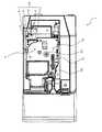
図2は、上記タグラベル作成装置1の全体構造を表す斜視図である。図2において、タグラベル作成装置1は、上記PC118からの操作に基づき、装置内で印字付き無線タグラベルの作成を行うものである。タグラベル作成装置1は、外郭に略六面体(略立方体)形状の筐体200を有する装置本体2と、この装置本体2の上面(上部)に開閉可能に(又は着脱可能としてもよい)設けられた開閉蓋(蓋体)3とを有している。 FIG. 2 is a perspective view showing the overall structure of the tag
装置本体2の筐体200は、装置前方側(図2中、左手前側)に位置し、装置本体2内で作成された無線タグラベルT(後述)を外部に排出するラベル排出口(排出口)11を備えた前壁10と、この前壁10のうちラベル排出口11の下方に設けられ下端が回動可能に支持された前蓋12とを備えている。 The
前蓋12は押部13を備えており、この押部13を上方より押し込むことで前蓋12が前方に開放されるようになっている。また、前壁10のうち上記開閉ボタン4の下方には、タグラベル作成装置1の電源のオン・オフを行う電源ボタン14が設けられている。この電源ボタン14の下方には、装置本体2内に配設された切断機構15を使用者の手動操作で駆動するためのカッター駆動ボタン16が設けられ、このボタン16が押されることで印字済タグラベル用テープ109(後述の図5参照)を所望の長さにカットして無線タグラベルT(ラベル)を作成するようになっている(なお、後述のように切断機構15は基本的には自動切断を行う)。 The
開閉蓋3は、装置本体2の図2中右奥側の端部にて回動可能に軸支され、バネ等の付勢部材を介して常時開放方向に付勢されている。そして、装置本体2の上面に開閉蓋3に隣接するように配置された開閉ボタン4が押されることにより、開閉蓋3と装置本体2とのロックが解除され、上記付勢部材の作用により開放される。なお、開閉蓋3の中央側部には、透明カバーで覆われた透視窓5が設けられている。 The opening /
図3は、タグラベル作成装置1の内部の内部ユニット20の構造(但し後述するループアンテナLCは省略)を表す斜視図である。図3において、内部ユニット20は、概略的には、カートリッジ(無線タグ回路素子カートリッジ)7を収納するカートリッジホルダ6(ロール設置部)と、いわゆるサーマルヘッドである印字ヘッド(印字手段)23を備えた印字機構21と、固定刃40及び可動刃41を備えた切断機構(切断手段)15と、固定刃40及び可動刃41のテープ搬送方向下流側に位置し、ハーフカッタ34を備えたハーフカットユニット35(半切断手段)とが設けられている。 FIG. 3 is a perspective view showing the structure of the
カートリッジ7の上面には、例えば、カートリッジ7内に内蔵されている基材テープ101(ラベル用テープ)のテープ幅、テープの色等を表示するテープ特定表示部8が設けられている。また、カートリッジホルダ6には、ローラホルダ25が支持軸29により回動可能に枢支され、切換機構により印字位置(接触位置、後述の図5参照)とリリース位置(離反位置)とに切換可能とされている。このローラホルダ25には、プラテンローラ26及びテープ圧接ローラ28が回転可能に配設されており、ローラホルダ25が上記印字位置に切り換えられたときに、それらプラテンローラ26及びテープ圧接ローラ28が上記印字ヘッド23及びテープ送りローラ27に対し圧接されるようになっている。 On the upper surface of the
印字ヘッド23は多数の発熱素子を備えており、カートリッジホルダ6に立設されたヘッド取付部24に取り付けられている。 The
切断機構15は、固定刃40と、金属部材で構成された可動刃41とを備えている。カッターモータ43(後述の図10参照)の駆動力が、カッターハスバギヤ42、ボス50、長孔49を介して可動刃41の柄部46に伝達されて可動刃が回転し、固定刃40とともにカット動作を行う。この切断状態は、カッターハスバギヤ用カム42Aの作用により切り替わるマイクロスイッチ126により検出される。 The
ハーフカットユニット35は、受け台38とハーフカッタ34とが対向して配置され、さらにガイド固定部36Aにより第1ガイド部36と第2ガイド部37とが側板44(後述の図5参照)に取り付けられている。ハーフカッタ34は、所定の回動支点(図示せず)を中心として、ハーフカッターモータ129(後述の図10参照)の駆動力によって回動する。受け台38の端部には受け面38Bが形成されている。 In the half-
図4は、上記装置本体2から開閉蓋3及びカートリッジ7を取り外した状態のカートリッジホルダ6の上面図である。 FIG. 4 is a top view of the
図4において、カートリッジホルダ6は、装置本体2にカートリッジ7を着脱可能に嵌め合わせることができる凹所として設けられている。カートリッジホルダ6の底に位置するホルダ底面6aには、上記印字ヘッド23のほか、カートリッジセンサCSと、リボン巻取りローラ駆動軸107(詳細は後述)と、テープ送りローラ駆動軸108(詳細は後述)とが設けられている。 In FIG. 4, the
後述のように、カートリッジホルダ6には複数種類のカートリッジ7が装着可能となっている。そして、それらのうちいずれの種類のカートリッジ7が装着されたか(=カートリッジ情報)を検出するために、カートリッジホルダ6に、複数のセンサ要素81(後述の図6参照)からなる上記カートリッジセンサCS(=情報取得手段)が設けられている。このカートリッジセンサCSとしては、種々のものが使用可能であるが、図示の例では、接触式のメカニカルスイッチを用い機械的検出を行うものである。 As will be described later, a plurality of types of
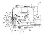
図5は、図3に示した内部ユニット20の構造を(カートリッジ7の取り付け状態で)表す平面図である。 FIG. 5 is a plan view showing the structure of the
図5において、上記カートリッジホルダ6は、カートリッジ7のテープ排出部30より排出されさらに上記ラベル排出口11から排出される印字済タグラベル用テープ109の幅方向の向きが、鉛直上下方向となるようにカートリッジ7を収納する。 In FIG. 5, the
また、内部ユニット20には、ラベル排出機構22と、ループアンテナLC(通信手段)とが設けられている。 The
ラベル排出機構22は、切断機構15において切断された後の印字済タグラベル用テープ109(言い換えれば無線タグラベルT、以下同様)をラベル排出口11(図2参照)より排出するものである。すなわちラベル排出機構22は、テープ排出モータ123(後述の図10参照)の駆動力により回転する駆動ローラ51と、この駆動ローラ51に対して印字済タグラベル用テープ109を挟んで対向する押圧ローラ52と、印字済タグラベル用テープ109に設けられた識別マークPM(=被検出マーク。後述の図7参照)を検出するマークセンサ127(マーク検出手段)とを有している。このとき、上記ラベル排出口11の内側には、印字済タグラベル用テープ109をラベル排出口11へ案内するための第1案内壁55,56及び第2案内壁63,64が設けられている。第1案内壁55,56及び第2案内壁63,64はそれぞれ一体に形成され、上記固定刃40と可動刃41とでカットされた印字済タグラベル用テープ109(無線タグラベルT)の排出位置において、互いに所定の間隔を隔てられるように配置されている。 The
ループアンテナLCは、押圧ローラ52をその径方向中心に位置させるようにしつつ当該押圧ローラ52の近傍に配置されており、磁気誘導(電磁誘導、磁気結合、その他磁界を介して行われる非接触方式を含む)により上記基材テープ101(貼り合わせ後は印字済タグラベル用テープ109、以下同様)に備えられる無線タグ回路素子Toに対し、無線通信を介しアクセス(情報読み取り又は情報書き込み)を行うようになっている。 The loop antenna LC is arranged in the vicinity of the
なお、上記のような読み取り又は書き込みの際、生成された無線タグラベルTの無線タグ回路素子ToのタグIDとそのIC回路部151から読みとられた情報(又はIC回路部151に書き込まれた情報)との対応関係は、前述のルートサーバRSに記憶され、必要に応じて参照できるようになっている。 At the time of reading or writing as described above, the tag ID of the RFID tag circuit element To of the generated RFID label T and information read from the IC circuit unit 151 (or information written to the IC circuit unit 151) ) Is stored in the above-described route server RS and can be referred to as necessary.
また、テープ送りローラ駆動軸(搬送手段)108及びリボン巻取りローラ駆動軸107は、印字済タグラベル用テープ109及びインクリボン105(後述)の搬送駆動力をそれぞれ与えるものであり、互いに連動して回転駆動される。 The tape feed roller driving shaft (conveying means) 108 and the ribbon take-up
図6は、上記カートリッジセンサCSの構成の一例を表す説明図である。 FIG. 6 is an explanatory diagram showing an example of the configuration of the cartridge sensor CS.
図6において、カートリッジセンサCSは、この例では、上記センサ要素81を複数対(この例では3対。上記図4の例では5対)備えている。各センサ要素81は、バネ部材81Aと、このバネ部材81Aにより付勢される検出ピン81Bと、この検出ピン81Bに備えられた可動接触片81Cと、2個の固定接点81D,81Dとから構成されている。そして、検出ピン81Bは、バネ部材81Aで付勢されることによってカートリッジ7側に設けられた被検出部190(相関記録部)の識別子190A〜Cに対し接触するようになっている。この結果、被検出部190の凹凸形状に応じ、凸部となる識別子(図示の例では識別子190B)に接触した検出ピン81Bは、可動接触片81Cを介し固定接点81D,81Dが導通することにより制御回路110へ検出信号を出力する。その一方、凹部となる識別子(図示の例では識別子190A,190C)に接触した検出ピン81Bは、2つの固定接点81D,81Dのうち一方(図示下方のもの)が可動接触片81Cに接触しないため、上記検出信号を出力しない。このようにして生じる各センサ要素81からの信号出力・不出力に基づき、制御回路110において被検出部190の凹凸形状を検出するようになっている。 In FIG. 6, the cartridge sensor CS includes a plurality of pairs of
本実施形態では、各識別子190A〜Cは、上記凹凸の有無によって、カートリッジ7のカートリッジ情報(カートリッジ7がタグラベル作成用であるかタグを有しない通常のラベル作成用であるかという情報や、タグラベル作成用である場合には基材テープ101内における無線タグ回路素子の配置間隔等のテープ種類情報等)を表している。そして、上記カートリッジセンサCSは、当該カートリッジ7に関するそのカートリッジ情報を検出し制御回路110へ出力する。これにより、制御回路110は通信回線NWを介して情報サーバISにアクセスし、上記入力された検出信号とひもづけされたカートリッジ情報を取得できるようになっている。 In this embodiment, each of the
以上のようにして、カートリッジセンサCSからの信号(被検出部を検出した検出信号)により、カートリッジホルダ6に装着されたカートリッジ7の上記カートリッジ情報が取得される。なお、被検出部190としては、その他、バーコード(カートリッジセンサCSに代えてバーコードセンサにより検出)や、別途の無線タグ回路素子(カートリッジセンサCSに代えて無線タグ情報読み取り装置により検出)を用いることも考えられる。その他光学的又は磁気的な被検出部を設け、それらに対し光学的又は磁気的に検出を行うようにしてもよい。 As described above, the cartridge information of the
図7は、上記カートリッジ7の詳細構造を模式的に表す拡大平面図である。図7において、カートリッジ7は、筐体7Aと、この筐体7A内に配置され帯状の基材テープ101が巻回された第1ロール102(タグテープロール、ラベル用テープロール。実際は渦巻き状であるが、図では簡略的に同心円状に示す)と、上記基材テープ101と略同じ幅である透明な上記カバーフィルム103(被印字媒体層)が巻回された第2ロール104(実際は渦巻き状であるが、図では簡略的に同心円状に示す)と、インクリボン105(熱転写リボン、但し被印字テープが感熱テープの場合は不要)を繰り出すリボン供給側ロール211と、印字後のリボン105を巻取るリボン巻取りローラ106と、カートリッジ7のテープ排出部30の近傍に回転可能に支持されたテープ送りローラ27(圧着手段)と、搬送位置規制手段として機能するガイドローラ112とを有する。 FIG. 7 is an enlarged plan view schematically showing the detailed structure of the
テープ送りローラ27は、上記基材テープ101と上記カバーフィルム103とを押圧し接着させ上記印字済タグラベル用テープ109としつつ、図7中矢印Aで示す方向にテープ送りを行う(=圧着ローラとしても機能する)。 The
第1ロール102は、リール部材102aの周りに、長手方向に複数の無線タグ回路素子Toが所定の等間隔で順次形成された上記基材テープ101を巻回している。基材テープ101はこの例では4層構造となっており(図7中部分拡大図参照)、内側に巻かれる側(図7中右側)よりその反対側(図7中左側)へ向かって、適宜の粘着材からなる粘着層101a、PET(ポリエチレンテレフタラート)等から成る色付きのベースフィルム101b(基材層)、適宜の粘着材からなる粘着層101c(貼り付け用粘着剤層)、剥離紙101d(剥離材層)の順序で積層され構成されている。 The
ベースフィルム101bの裏側(図7中左側)には、ループコイル形状に構成され情報の送受信を行うループアンテナ152(タグ側ループアンテナ)がこの例では一体的に設けられており、これに接続され情報を記憶するIC回路部151が形成され、これらによって無線タグ回路素子Toが構成されている。 On the back side (left side in FIG. 7) of the
ベースフィルム101bの表側(図7中右側)には、後にカバーフィルム103を接着するための上記粘着層101aが形成され、またベースフィルム101bの裏側(図7中左側)には、無線タグ回路素子Toを内包するように設けた上記粘着層101cによって上記剥離紙101dがベースフィルム101bに接着されている。 The
なお、上記剥離紙101dは、最終的にラベル状に完成した無線タグラベルTが所定の商品等に貼り付けられる際に、これを剥がすことで粘着層101cにより当該商品等に接着できるようにしたものである。また、この剥離紙101dの表面には、各無線タグ回路素子Toに対応した(及び後述の余白領域S1にも対応した)所定の位置(この例では、搬送方向前方側のループアンテナ152の先端よりさらに前方側の位置)に、搬送制御用の所定の識別マーク(この例では黒塗りの識別マーク)PMが(この例では印刷により)設けられている。なお識別マークとしては、レーザ加工等により基材テープ101を貫通する孔を穿孔したり、トムソン型での加工穴を設ける等でもよい(後述の図13(c)参照)。 The
なお、本実施形態の特徴として、前述したように互いに異なる基材テープ101を収納した複数種類のカートリッジ7をカートリッジホルダ6に装着可能であるが、このときいずれのカートリッジ7の基材テープ101についても、上記剥離紙101dの形成態様は同一(共通)となっている(詳細は後述)。 As a feature of the present embodiment, as described above, a plurality of types of
第2ロール104は、リール部材104aの周りに上記カバーフィルム103を巻回している。第2ロール104より繰り出されるカバーフィルム103は、その裏面側(すなわち上記基材テープ101と接着される側)に配置された上記リボン供給側ロール211及び上記リボン巻取りローラ106で駆動されるリボン105が、上記印字ヘッド23に押圧されることで当該カバーフィルム103の裏面に接触させられるようになっている。 The
リボン巻取りローラ106及びテープ送りローラ27は、それぞれカートリッジ7外に設けた例えばパルスモータである搬送用モータ119(図3及び後述の図10参照)の駆動力が図示しないギヤ機構を介し上記リボン巻取りローラ駆動軸107及びテープ送りローラ駆動軸108に伝達されることによって連動して回転駆動される。なお、上記印字ヘッド23は、テープ送りローラ27よりカバーフィルム103の搬送方向上流側に配置されている。 The ribbon take-up
上記構成において、上記第1ロール102より繰り出された基材テープ101は、テープ送りローラ27へと供給される。一方、第2ロール104より繰り出されるカバーフィルム103は、その裏面側(すなわち上記基材テープ101と接着される側)に配置されリボン供給側ロール211とリボン巻取りローラ106とにより駆動されるインクリボン105が、上記印字ヘッド23に押圧されて当該カバーフィルム103の裏面に接触させられる。 In the above configuration, the
そして、カートリッジ7が上記カートリッジホルダ6に装着されロールホルダ25が上記リリース位置から上記印字位置に移動されると、カバーフィルム103及びインクリボン105が印字ヘッド23とプラテンローラ26との間に狭持されるとともに、基材テープ101及びカバーフィルム103がテープ送りローラ27と圧着ローラ28との間に狭持される。そして、搬送用モータ119の駆動力によってリボン巻取りローラ106及びテープ送りローラ27が図7中矢印B及び矢印Cで示す方向にそれぞれ同期して回転駆動される。このとき、前述のテープ送りローラ駆動軸108と上記圧着ローラ28及びプラテンローラ26はギヤ機構(図示せず)にて連結されており、テープ送りローラ駆動軸108の駆動に伴いテープ送りローラ27、圧着ローラ28及びプラテンローラ26が回転し、第1ロール102から基材テープ101が繰り出され、上述のようにテープ送りローラ27へ供給される。一方、第2ロール104からはカバーフィルム103が繰り出されるとともに、印刷駆動回路120(後述の図10参照)により印字ヘッド23の複数の発熱素子が通電される。この結果、カバーフィルム103の裏面に、貼り合わせ対象となる基材テープ101上の無線タグ回路素子Toに対応した印字R(タグ印字。後述の図12参照)が印刷される。そして、上記基材テープ101と上記印刷が終了したカバーフィルム103とが上記テープ送りローラ27及び圧着ローラ28により接着されて一体化されて印字済タグラベル用テープ109として形成され、テープ排出部30(図5参照)よりカートリッジ7外へと搬出される。カバーフィルム103への印字が終了したインクリボン105は、リボン巻取りローラ駆動軸107の駆動によりリボン巻取りローラ106に巻取られる。 When the
そして、上述のように貼り合わされて生成された印字済タグラベル用テープ109に対し上記ループアンテナLCにより無線タグ回路素子Toに情報読み取り又は書き込みが行われた後、自動的にあるいは上記カッター駆動ボタン16(図2参照)を操作することにより切断機構15によって印字済タグラベル用テープ109が(切断線CLの位置で、後述の図12や図14参照)切断され、無線タグラベルTが生成される。この無線タグラベルTは、その後さらに上記ラベル排出機構22によってラベル排出口11(図2、図5参照)から排出されるようになっている。 Then, after reading or writing information to the RFID circuit element To by the loop antenna LC with respect to the
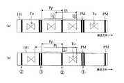
図8(a)及び図8(b)は、上記第1ロール102より繰り出された基材テープ101を図7中矢印D方向から(すなわち剥離紙101d側から)見た状態を表す概念的矢視図である。前述したように本実施形態では複数種類のカートリッジ7が装着可能であり、それぞれにおける基材テープ101の態様(この例では識別マークPMの配置ピッチと無線タグ回路素子Toの配置ピッチとの関係)が異なる。これら図8(a)及び図8(b)は、互いに異なる種類の基材テープ101の例を示したものである。 8 (a) and 8 (b) are conceptual arrows showing a state in which the
図9(a)及び図9(b)は、理解の容易のために、上記図8(a)及び図8(b)で示した識別マークPMの配置ピッチと無線タグ回路素子Toの配置ピッチとの関係(=相関)を、概念的に表した説明図である。 9A and 9B show the arrangement pitch of the identification mark PM and the arrangement pitch of the RFID circuit element To shown in FIGS. 8A and 8B for easy understanding. It is explanatory drawing which represented the relationship (= correlation) with (2) notionally.
すなわち、図8(a)及び図9(a)の基材テープ101、及び、図8(b)及び図9(b)の基材テープ101のいずれにおいても、識別マークPMの配置ピッチは固定値Ppである。そして、この例では、無線タグ回路素子Toの配置ピッチPt(固定値)は、Pt=n×Pp(n:1以上の整数)の関係となっている。 That is, the arrangement pitch of the identification marks PM is fixed in both the
そして、図8(a)及び図9(a)の基材テープ101はn=1の例であり、Pt=Pp、すなわち隣接する識別マークPM,PM間に1つの無線タグ回路素子Toが必ず配置されている。この基材テープ101は、隣接識別マークPM,PM間の長さ(識別マークPMの配置ピッチPp)に略等しい長さ(あるいはそれ以下の長さ)の無線タグラベルTを作成するためのものである(後述の図12(a)及び図12(b)参照)。 The
一方、図8(b)及び図9(b)の基材テープ101はn=2の例であり、Pt=2Pp、すなわち無線タグ回路素子Toは識別マークPMの2倍のピッチで配列されている。この結果、図9(b)に示すように、互いの間に無線タグ回路素子Toが存在しない(空白である)ような隣接する2つの識別マークPM,PMが存在する配置となっている。この基材テープ101は、隣接識別マークPM,PM間の長さ(=配置ピッチPp)の2倍に略等しい長さ(あるいは1倍より大きく2倍以下の長さ)の無線タグラベルTを作成するためのものである(後述の図12(a)及び図12(b)、図14(a)及び図14(b)参照)。 On the other hand, the
このようにして、本実施形態では、nの値に応じて複数の相関となる複数種類の基材テープ101を用いることができ、この例ではn=1とn=2の場合を例示しているものである。なお、各識別マークPMのそれぞれは、本実施形態では単一の態様に共通化されたマークで構成されている(=1本の固定幅のマーク。後述する第2実施形態のように1本マークと2本マークとが混在しない)。 Thus, in this embodiment, a plurality of types of
そして、前述のようにカートリッジ7には(カートリッジセンサCSで検出可能な)被検出部190が設けられており、この検出によってカートリッジ7の種類がいずれであるかが判別される。このことは、すなわち上記相関がどのようなものであるか(この例ではnの値が1以上のいくつであるか)の相関情報を表すこととなる。この結果、上記被検出部190は、無線タグ回路素子Toの配列規則性(この例では配置ピッチPt)の、上記識別マークPMのピッチPpに対する関係がいずれの相関であるかを表す相関情報を記録した相関記録部として機能することとなる。 As described above, the
図10は、第1実施形態のタグラベル作成装置1の制御系を表す機能ブロック図である。図10において、このタグラベル作成装置1の制御基板(図示せず)上には、制御回路110が配置されている。 FIG. 10 is a functional block diagram showing a control system of the tag
制御回路110には、内部にタイマ111Aを備え各機器を制御するCPU111と、このCPU111にデータバス112を介して接続された入出力インターフェース113と、CGROM114と、ROM115,116と、RAM117とが設けられている。 The
ROM116には、上記PC118からの操作入力信号に対応させて、印字バッファのデータを読み出して上記印字ヘッド23、搬送用モータ119、テープ排出モータ65を駆動する印字駆動制御プログラム、印字終了した場合に印字済タグラベル用テープ109を切断位置まで搬送用モータ119を駆動して搬送し、上記カッターモータ43を駆動して印字済タグラベル用テープ109を切断する切断駆動制御プログラム、切断された印字済タグラベル用テープ109(=無線タグラベルT)をテープ排出モータ65を駆動してラベル排出口11から強制的に排出するテープ排出プログラム、無線タグ回路素子Toに対する問いかけ信号や書き込み信号などのアクセス情報を生成して送信回路306に出力する送信プログラム、受信回路307から入力された応答信号などを処理する受信プログラム、その他タグラベル作成装置1の制御上必要な各種のプログラムが格納されている。CPU111は、このようなROM116に記憶されている各種プログラムに基づいて各種の演算を行う。 The
RAM117には、テキストメモリ117A、印字バッファ117B、パラメータ記憶エリア117E等が設けられている。テキストメモリ117Aには、PC118から入力された文書データが格納される。印字バッファ117Bには、複数の文字や記号等の印字用ドットパターンや各ドットの形成エネルギ量である印加パルス数等がドットパターンデータとして格納され、印字ヘッド23はこの印字バッファ117Bに記憶されているドットパターンデータに従ってドット印字を行う。パラメータ記憶エリア117Eには、各種演算データや、情報読み取り(取得)が行われた無線タグ回路素子To(前述)のタグ識別情報(タグID)等が記憶される。 The
入出力インターフェース113には、PC118と、印字ヘッド23を駆動するための上記印刷駆動回路120と、搬送用モータ119を駆動するための搬送用モータ駆動回路121と、カッターモータ43を駆動するためのカッターモータ駆動回路122と、ハーフカッターモータ129を駆動するためのハーフカッターモータ駆動回路128と、テープ排出モータ65を駆動するためのテープ排出モータ駆動回路123と、上記ループアンテナLCを介して無線タグ回路素子Toにアクセスする(読み取り/書き込みを行う)ために、搬送波を発生させるとともに入力される制御信号に基づいて上記搬送波を変調した質問波(送信信号)を出力する送信回路306と、無線タグ回路素子Toから上記ループアンテナLCを介して受信された応答信号の復調を行い出力する受信回路307と、識別マークPMを検出する上記マークセンサ127とが接続されている。 The input /
このような制御回路110を核とする制御系において、PC118を介して文字データ等が入力された場合、そのテキスト(文書データ)がテキストメモリ117Aに順次記憶されるとともに、印字ヘッド23が駆動回路120を介して駆動され、各発熱素子が1ライン分の印字ドットに対応して選択的に発熱駆動されて印字バッファ117Bに記憶されたドットパターンデータの印字を行い、これと同期して搬送用モータ119が駆動回路121を介してテープの搬送制御を行う。また、送信回路306が制御回路110からの制御信号に基づき搬送波の変調制御を行って上記質問波を出力するとともに、受信回路307は制御回路110からの制御信号に基づき復調した信号の処理を行う。 In such a control system having the
図11は、上記無線タグ回路素子Toの機能的構成を表す機能ブロック図である。この図11において、無線タグ回路素子Toは、タグラベル作成装置1のループアンテナLCと電磁誘導により非接触で信号の送受信を行う上記ループアンテナ152と、このループアンテナ152に接続された上記IC回路部151とを有している。 FIG. 11 is a functional block diagram showing a functional configuration of the RFID circuit element To. In FIG. 11, the RFID circuit element To includes the
IC回路部151は、ループアンテナ152により受信された質問波を整流する整流部153と、この整流部153により整流された質問波のエネルギを蓄積し駆動電源とするための電源部154と、上記ループアンテナ152により受信された質問波からクロック信号を抽出して制御部155に供給するクロック抽出部156と、所定の情報信号を記憶し得るメモリ部157と、上記ループアンテナ152に接続された変復調部158と、上記整流部153、クロック抽出部156、及び変復調部158等を介して上記無線タグ回路素子Toの作動を制御するための上記制御部155とを備えている。 The
変復調部158は、ループアンテナ152により受信された上記タグラベル作成装置1のループアンテナLCからの通信信号の復調を行うとともに、上記制御部155からの返信信号に基づき、ループアンテナ152で受信した質問波を変調し、ループアンテナ152より応答波として再送信する。 The modulation /
制御部155は、上記変復調部158により復調された受信信号を解釈し、上記メモリ部157において記憶された情報信号に基づいて返信信号を生成し、上記変復調部158により返信する制御等の基本的な制御を実行する。 The
クロック抽出部156は受信した信号からクロック成分を抽出して制御部155にクロックを抽出するものであり、受信した信号のクロック成分の周波数に対応したクロックを制御部155に供給する。 The
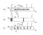
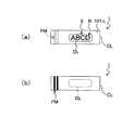
図12(a)及び図12(b)は、上述のような構成であるタグラベル作成装置1により無線タグ回路素子Toの情報書き込み(又は読み取り)及び印字済タグラベル用テープ109の切断が完了して形成された無線タグラベルTの外観の一例を表す図である。この例では、上記図8(a)及び図9(a)で示した基材テープ101を用いて作成した、識別マークPMの配置ピッチPpに略等しい長さの無線タグラベルTを表しており、図12(a)はその上面図、図12(b)は下面図である。また図13(a)は図12中XIIIA−XIIIA′断面による横断面図を反時計方向に90°回転させた図であり、図13(b)は図12(a)中XIIIB−XIIIB′断面による横断面図を反時計方向に90°回転させた図である。 12 (a) and 12 (b) show that the tag
これら図12(a)、図12(b)、図13(a)、及び図13(b)において、無線タグラベルTは、前述したように図7に示した4層構造にカバーフィルム103が加わった5層構造となっており、カバーフィルム103側(図13中上側)よりその反対側(図13中下側)へ向かって、カバーフィルム103、粘着層101a、ベースフィルム101b、粘着層101c、剥離紙101dで5層を構成している。そして、前述のようにベースフィルム101bの裏側に設けられたループアンテナ152を含む無線タグ回路素子Toが、ベースフィルム101bと粘着層101cとの接着面内にそれぞれ備えられるとともに、カバーフィルム103の裏面に無線タグ回路素子Toの記憶情報等に対応したラベル印字R(この例では「ABCDEF」の文字)が印刷されている。また、無線タグラベルTの無線タグ回路素子Toのメモリ部157には、固有の識別情報であるタグID(アクセスID)が記憶されている。 12 (a), 12 (b), 13 (a) and 13 (b), the RFID label T has a
また、無線タグラベルTにおいて、剥離紙101d以外の層、すなわちカバーフィルム103と粘着層101aとベースフィルム101bと粘着層101cに、既に述べたように上記ハーフカッタ34によってテープ幅方向に略沿ってハーフカット線HC(半切断部位)が形成されている。すなわち、無線タグラベルTは、カバーフィルム103のラベル印字Rが印刷される印字領域Sに対応する部分である無線タグラベル本体Taと、上記ラベル印字Rが印刷されない余白領域S1に対応する部分である余白部分Tbとから構成され(図12(a)参照)、それら無線タグラベル本体Taと余白部分Tbとが上記ハーフカット線HCにおいて剥離紙101dを介し連結された構成となっている。なお、前述の識別マークPMは上記余白部分Tbに設けられている。 Further, in the RFID label T, the layers other than the
また、上記では無線タグラベル本体Taのラベル長手方向一方側にのみハーフカット線HCを形成した場合を例にとって説明したが、これに限られず、他方側にもハーフカッタ34でハーフカット線HCを設け、これを介し上記余白部分Tbと同様の部分を設けるようにしてもよい。この場合の他方側のハーフカット線HCの位置は(例えば印字文字数の大小等に応じ)可変としてもよい。但しこの場合、無線タグ回路素子Toの通信機能を阻害しないように、ハーフカット線HCの位置を、少なくとも無線タグ回路素子Toの搬送方向後端部(すなわちアンテナ152の後端部)よりも搬送方向後端側とすることが望ましい。 In the above description, the case where the half cut line HC is formed only on one side in the label longitudinal direction of the RFID label main body Ta has been described as an example. However, the present invention is not limited to this. Through this, a portion similar to the margin portion Tb may be provided. In this case, the position of the other half-cut line HC may be variable (for example, depending on the number of print characters). However, in this case, the position of the half-cut line HC is transported at least more than the rear end of the RFID tag circuit element To in the conveyance direction (that is, the rear end of the antenna 152) so as not to disturb the communication function of the RFID circuit element To. It is desirable to be the rear end side in the direction.
なお既に述べたように識別マークPMとして図13(a)及び図13(b)に示すような黒塗りのマーキングを設けるのに代え、図13(c)に示すように、識別マークPMとして、レーザ加工等により基材テープ101を略貫通する孔を孔設する等でもよい。 As already described, instead of providing the black marking as shown in FIGS. 13A and 13B as the identification mark PM, as shown in FIG. 13C, as the identification mark PM, For example, a hole that substantially penetrates the
図14(a)及び図14(b)は、タグラベル作成装置1により作成された無線タグラベルTの外観の他の例を表す図である。この例では、上記図8(b)及び図9(b)に示した基材テープ101を用いて作成した、識別マークPMの配置ピッチPpの略2倍の長さの無線タグラベルTを表しており、図14(a)はその上面図、図14(b)は下面図である。 FIG. 14A and FIG. 14B are diagrams illustrating another example of the appearance of the RFID label T created by the tag
これら図14(a)及び図14(b)に示す無線タグラベルTも、上記同様、カバーフィルム103が加わった5層構造となっている(横断面構造は図13(a)及び図13(b)と同様であるので図示省略する)。カバーフィルム103の裏面の印字領域S(印字可能最大長さ)は、この場合は上記図12(a)に示した構造の約2倍(例えば2倍よりやや大きい)となっており、無線タグ回路素子Toの記憶情報等に対応したラベル印字R(この例では「ABCDEFGHIJKLMN」の文字)が印刷されている。 14A and 14B, the RFID label T shown in FIGS. 14A and 14B has a five-layer structure to which a
その他、無線タグラベル本体Taと余白部分Tbとから構成されてそれらが上記ハーフカット線HCにおいて連結されている等については、上記と同様であるので説明を省略する。 In addition, since the RFID label main body Ta and the margin portion Tb are connected to each other at the half-cut line HC, the description is omitted.
なお、この例では、図14(a)に示すように、印字文字数が多かった結果操作者により図8(b)及び図9(b)に示した基材テープ101が使用され、図12(a)に比べて約2倍の長さの無線タグラベルTが作成された場合を例示した。しかしながらこのような印字文字数の多さだけに限られず、他の理由(その他の印字態様の変化、操作者の好み、ラベル使用用途等)の場合も考えられる。図14(c)に、そのような一例として、文字数は同じだったが各印字文字の大きさを大きくするために操作者により図8(b)及び図9(b)に示した基材テープ101が使用され、図12(a)に比べて約2倍の長さの無線タグラベルTが作成された場合を示す。 In this example, as shown in FIG. 14 (a), the operator uses the
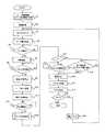
以上説明したように、本実施形態の特徴は、無線タグ回路素子Toの配置ピッチが異なる複数種類の基材テープ101を用いて複数種類の無線タグラベルTを作成できることである。そしてその際には、前述したようにカートリッジ7に設けた被検出部をカートリッジセンサCSで検出することで基材テープ101の種類を特定し、これに応じてテープ搬送制御や位置決め、さらにはこれらと関連づけた印字制御、通信制御、切断制御等を実行する。図15は、このような制御を行うために上記制御回路110によって実行される制御手順を表すフローチャートである。 As described above, the feature of the present embodiment is that a plurality of types of RFID label T can be created using a plurality of types of
この図15において、上記PC118を介しタグラベル作成装置1による所定の無線タグラベル作成操作が行われるとこのフローが開始される。 In FIG. 15, when a predetermined RFID label producing operation is performed by the tag
まずステップS1において、カートリッジセンサCSの検出信号に基づき、対応する基材テープ101のテープ種類情報(前述の例では図8(a)及び図9(a)に示す通常長さラベル作成用のものであるか、図8(b)及び図9(b)に示す2倍長ラベル作成用のものであるか等。言い換えればラベル長さ情報)を取得する。例えば、制御回路110内の適宜の箇所(例えばRAM117やその他のメモリ等)に、被検出部の識別子とこれに対応するカートリッジ種類(又はテープ種類)とを関連づけたテーブルの形で記憶しておき、これに基づいて上記基材テープ101のテープ種類情報を取得するようにしてもよい。 First, in step S1, based on the detection signal of the cartridge sensor CS, the tape type information of the corresponding base tape 101 (in the above example, for producing the normal length label shown in FIGS. 8A and 9A). Or for double-length label creation shown in FIGS. 8B and 9B, in other words, label length information). For example, it is stored in the form of a table in which the identifier of the detected portion and the corresponding cartridge type (or tape type) are associated with each other in the control circuit 110 (for example, the
その後、ステップS2に移って準備処理を実行する。すなわち、上記PC118からの操作信号を(通信回線NW及び入出力インターフェース113を介して)入力し、この操作信号に基づき、印刷データ、タグ書き込みデータ、ハーフカット位置(ハーフカット線HCの位置)、フルカット位置(切断線CLの位置)、及び印刷終了位置等の設定を行なう。このとき、ハーフカット位置及びフルカット位置は、上記カートリッジ情報に基づき各カートリッジの種類ごと(言い換えれば基材テープ101の種類ごと)に一意的に固定して決定される。なお、ハーフカット位置は無線タグ回路素子Toの位置と重ならないように設定される。 Then, it moves to step S2 and performs a preparation process. That is, an operation signal from the
次に、ステップS3において、初期化設定を行う。ここでは、アンテナLCから無線タグ回路素子Toへ通信を行う際、無線タグ回路素子Toからの応答がない場合に通信再試行(リトライ)を行う回数(アクセス試行回数)をカウントするための変数M,Nや、所定リトライ回数だけ通信再試行しても通信不能であった場合を表す通信エラーフラグFを0に初期化設定する。 Next, in step S3, initialization setting is performed. Here, when performing communication from the antenna LC to the RFID circuit element To, a variable M for counting the number of times of communication retry (retry) when there is no response from the RFID circuit element To (number of access attempts). , N, or a communication error flag F indicating that the communication is not possible even if the communication is retried for the predetermined number of retries, is initialized to 0.
その後、ステップS4に移り、テープ搬送を開始する。ここでは、入出力インターフェース113を介し搬送用モータ駆動回路121に制御信号を出力し、搬送用モータ121の駆動力によってテープ送りローラ27及びリボン巻取りローラ106を回転駆動させる。さらに、テープ排出モータ駆動回路123を介してテープ排出モータ65に制御信号を出力し、駆動ローラ51を回転駆動させる。これらにより、第1ロール102から基材テープ101が繰り出されテープ送りローラ27へ供給されるとともに、第2ロール104からはカバーフィルム103が繰り出され、これら基材テープ101とカバーフィルム103とが上記テープ送りローラ27及びサブローラ28により接着されて一体化されて印字済タグラベル用テープ109として形成され、カートリッジ7外方向からさらにタグラベル作成装置1外方向へと搬送される。 Then, it moves to step S4 and starts tape conveyance. Here, a control signal is output to the transport
その後、ステップS6において、印字済タグラベル用テープ109に設けられた上記識別マークPMがマークセンサ127により検出され、当該マークセンサ127より入出力インターフェース113を介し検出信号が入力されたかどうか(言い換えればカバーフィルム103が印字ヘッド23による印刷開始位置まで到達したかどうか)を判定する。識別マークPMが検出されるまで判定が満たされずこの手順を繰り返し、検出されたら判定が満たされて次のステップS7に移る。 Thereafter, in step S6, the identification mark PM provided on the
ステップS7では、入出力インターフェース113を介し印刷駆動回路120に制御信号を出力し、印字ヘッド23を通電して、カバーフィルム103のうち前述した印字領域Sに、ステップS2で取得した無線タグラベルTに対する印刷データに対応した文字、記号、バーコード等のラベル印字Rの印刷を開始する。 In step S7, a control signal is output to the
その後、ステップS8において、印字済タグラベル用テープ109が先のステップS1で設定した、無線タグラベルTの無線タグラベル本体Taと余白部分Tbとの境界のハーフカット位置(ハーフカッタ34がハーフカット線HCの位置に正対するような搬送方向位置)まで搬送されたかどうかを判定する。このときの判定は、例えば、上記ステップS6において識別マークPMを検出した後の搬送距離を所定の公知の方法で検出すればよい(パルスモータである搬送用モータ119を駆動する搬送用モータ駆動回路121の出力するパルス数をカウントする等)。ハーフカット位置に到達するまでは判定が満たされずこの手順を繰り返し、到達したら判定が満たされて次のステップS9に移る。 Thereafter, in step S8, the half-cut position (half-
ステップS9では、入出力インターフェース113を介し搬送用モータ駆動回路121及びテープ排出モータ駆動回路123に制御信号を出力し、搬送用モータ119及びテープ排出モータ65の駆動を停止して、テープ送りローラ27、リボン巻取りローラ106、駆動ローラ51の回転を停止する。これにより、カートリッジ7から繰り出された印字済タグラベル用テープ109が排出方向に移動する過程で、ステップS2で設定した対応する無線タグラベルTのハーフカット線HCの位置にハーフカットユニット35のハーフカッタ34が正対した状態で、第1ロール102からの基材テープ101の繰り出し、第2ロール104からのカバーフィルム103の繰り出し、及び印字済タグラベル用テープ109の搬送が停止する。またこのとき、入出力インターフェース113を介し印刷駆動回路120にも制御信号を出力し、印字ヘッド23の通電を停止して、上記ラベル印字Rの印刷を停止(印刷中断)する。 In step S9, control signals are output to the transport
その後、ステップS10で、入出力インターフェース113を介しハーフカッターモータ駆動回路128に制御信号を出力してハーフカッターモータ129を駆動し、ハーフカッタ34を回動させて、印字済タグラベル用テープ109のカバーフィルム103、粘着層101a、ベースフィルム101b、及び粘着層101cを切断してハーフカット線HCを形成するハーフカット処理を行う。 Thereafter, in
そして、ステップS11に移り、上記ステップS4と同様にして、テープ送りローラ27、リボン巻取りローラ106、駆動ローラ51を回転駆動させて印字済タグラベル用テープ109の搬送を再開するとともに、ステップS7と同様にして印字ヘッド23に通電してラベル印字Rの印刷を再開する。 Then, the process proceeds to step S11, and in the same manner as in step S4, the
その後、ステップS12において、搬送される印字済タグラベル用テープ109が所定値(例えば、無線タグ回路素子Toが上記アンテナLCへ略対向する位置に到達するだけの搬送距離。但し後述のタグ非存在区間の場合は除く)だけ搬送されたかどうかを判断する。このときの搬送距離判定も、上記ステップS8と同様に、パルスモータである搬送用モータ119を駆動する搬送用モータ駆動回路121の出力するパルス数をカウントする等により行えば足りる。 Thereafter, in step S12, the transported
次のステップS100では、ラベル作成処理を行う。すなわち、無線タグ回路素子Toの通信位置(例えば、少なくとも図8(a)や図9(a)の構成の基材テープ101において、対応する無線タグラベルTの無線タグ回路素子ToがアンテナLCとほぼ正対する位置)まで搬送したら搬送及び印字を停止して、無線タグ回路素子Toに対する情報送受信を行い、その後搬送及び印字を再開して印字を完了させ、対応する無線タグラベルTの形成を行う(詳細は後述の図16参照)。 In the next step S100, label creation processing is performed. That is, the communication position of the RFID circuit element To (for example, at least in the
以上のようにしてステップS100が終了したら、ステップS13に移り、上記ステップS100のラベル作成処理で上記フラグF=1となっているか(通信エラーが生じたか)どうかを判定する。通信エラーが生じていなければF=0のままであるから判定が満たされず、ステップS14に移る。 When step S100 is completed as described above, the process proceeds to step S13, and it is determined whether or not the flag F = 1 is set (whether a communication error has occurred) in the label creation process of step S100. If no communication error has occurred, F remains 0, so the determination is not satisfied, and the routine goes to Step S14.
ステップS14では、印字済タグラベル用テープ109が先のステップS2で設定した、無線タグラベルTの末端部のフルカット位置(切断機構15の可動刃41が無線タグラベルT末端のフルカット線CLの位置に正対するような搬送方向位置)まで搬送されたかどうかを判定する。このときの判定も、上記同様に、パルスモータである搬送用モータ119を駆動する搬送用モータ駆動回路121の出力するパルス数をカウントする等により行えば足りる。フルカット位置に到達するまでは判定が満たされずこの手順を繰り返し、到達したら判定が満たされてステップS16に移る。 In step S14, the
一方、上記ステップS13において、ステップS100のラベル作成処理において通信エラーが発生していた場合、フラグF=1となっていることから判定が満たされない。このような通信エラーは例えば以下のような場合に起こりうる。すなわち、例えばカートリッジホルダ6に、図8(a)や図9(a)のように隣接識別マークPM,PM間の区間のすべてに無線タグ回路素子Toが存在する(正確には、一方の識別マークPMがセンサ127によって検出された搬送タイミング(=搬送方向位置。すなわちテープ101,109がある搬送状態にある時期)から他方の識別マークPMがセンサ127によって検出された搬送タイミング(=搬送方向位置)との時間に、常に対応する無線タグ回路素子ToがアンテナLCに略対向する通信可能位置にある。本明細書中において「搬送方向位置」「区間」等の定義はすべて同様であるとする)のではなく、図8(b)や図9(b)のように1つおきに無線タグ回路素子Toが配置された基材テープ101が配置されたカートリッジ7が装着されたとする(このことは、前述したカートリッジセンサCSの検出信号に基づき、ステップS1で取得されたテープ種類情報によって識別される)。ここで、上述したように、ステップS100におけるラベル作成処理(無線タグ回路素子Toとの通信(試行)を含む。後述参照)は、ステップS6における識別マークPMの検出タイミングを契機として、これを基準にステップS8における判定及びステップS12における判定が満たされた搬送タイミングで実施される。このとき、ステップS6の識別マークPMの検出は、その搬送方向直後に無線タグ回路素子Toが位置する識別マークPM(図9(b)中(1)で示すもの)であるか、搬送方向しばらく無線タグ回路素子Toの空白領域が続く識別マークPM(図9(b)中(2)であるか)がこの段階では不明である。 On the other hand, in step S13, if a communication error has occurred in the label creation process in step S100, the determination is not satisfied because flag F = 1. Such a communication error can occur in the following cases, for example. That is, for example, in the
そこでとりあえず(1)の識別マークPMであるとみなして通信を行うことで、所定回数の再試行の間で通信可能であったら(1)の識別マークPMであり、通信不能であったら(2)の識別マークPMであることがわかる。すなわち、通信エラー発生時(F=0の場合)は、ステップS6で検出した識別マークPMが(2)のマークであったこと(以下適宜、「タグ非存在区間の場合」という)がわかるのである(=マーク判定手段)。ステップS100のラベル作成処理において通信エラーが発生しフラグF=1となっていた場合、上記ステップS13の判定が満たされなくなり、ステップS6で検出したものが識別マークPMが(2)のマークであった(タグ非存在区間であった)とみなして、ステップS15へ移る。 For the time being, it is assumed that it is the identification mark PM of (1), and communication is performed. If communication is possible during a predetermined number of retries, it is the identification mark PM of (1), and if communication is not possible (2 It can be seen that this is the identification mark PM. That is, when a communication error occurs (when F = 0), it can be seen that the identification mark PM detected in step S6 is the mark (2) (hereinafter referred to as “in the case of no tag section” as appropriate). Yes (= mark determination means). If a communication error occurs in the label creation process in step S100 and flag F = 1, the determination in step S13 is not satisfied, and the identification mark PM detected in step S6 is the mark (2). (It was a tag non-existing section), and the process proceeds to step S15.
ステップS15では、上記ステップS14とは異なる余白排出用フルカット位置へ到達したかどうかを判定する。すなわち上記ステップS14では、通信が正常に終了した無線タグ回路素子Toを備えた印字済タグラベルテープ109の後端側を切断して無線タグラベルT作成を完了するための、フルカット位置到達判定であった(ステップS1で取得したテープ種類情報で図8(a)や図9(a)のように隣接識別マークPM,PM間の区間のすべてに無線タグ回路素子Toが存在する基材テープ101であることが識別され、ステップS2での準備処理で対応する通常の切断線CLの位置設定がなされる)。これに対し、このステップS15では、図8(b)及び図9(b)の基材テープ101を用いて2倍長の無線タグラベルTが作成されるときは常にその搬送方向先端側に無線タグ回路素子Toが配置される(図14(a)及び図14(c)参照)ことを前提に、図9(b)の(2)で示す識別マークPMをステップS6で検出した場合は、(2)の識別マークPMから後続の(1)の識別マークPMまでの区間に対応する領域(センサ127が(2)の識別マークPMを検出した後、(1)の識別マークPMを検出するまでの搬送領域)を余白(余剰分)として排出するためのフルカット位置への到達判定である(ステップS1で取得したテープ種類情報で図8(b)や図9(b)のような基材テープ101であることが識別され、その後ステップS2での準備処理での切断線CLの位置設定に対応して、余白として切断排出すべき部分の長さの決定とフルカット位置の設定がなされる)。このときの判定も、上記同様に、パルスモータである搬送用モータ119を駆動する搬送用モータ駆動回路121の出力するパルス数をカウントする等により行えば足りる。余白排出用フルカット位置に到達するまでは判定が満たされずこの手順を繰り返し、到達したら判定が満たされてステップS16に移る。 In step S15, it is determined whether or not a blank cut full cut position different from that in step S14 has been reached. That is, step S14 is a full cut position arrival determination for cutting off the rear end side of the printed
ステップS16では、上記ステップS9と同様にして、テープ送りローラ27、リボン巻取りローラ106、駆動ローラ51の回転を停止して印字済タグラベル用テープ109の搬送を停止する。これにより、上記タグ非存在区間の場合には上記余白排出用フルカット位置に相当する切断線CLに、それ以外の場合にはステップS2で設定した切断線CLに、切断機構15の可動刃41が正対した状態で、第1ロール102からの基材テープ101の繰り出し、第2ロール104からのカバーフィルム103の繰り出し、及び印字済タグラベル用テープ109の搬送が停止する。 In step S16, similarly to step S9, the rotation of the
その後、ステップS17でカッターモータ駆動回路122に制御信号を出力してカッターモータ43を駆動し、切断機構15の可動刃41を回動させて、印字済タグラベル用テープ109のカバーフィルム103、粘着層101a、ベースフィルム101b、粘着層101c、及び剥離紙101dをすべて切断(分断)して切断線CLを形成するフルカット処理を行う。この切断機構15による分断によって印字済タグラベル用テープ109の先端側が残りの部分から切り離される。この結果、タグ非存在区間であった場合には当該切り離された部分が上記余白部分となり、それ以外の場合には当該切り離された部分が無線タグラベルTとなる。 Thereafter, in step S17, a control signal is output to the cutter
その後、ステップS18に移り、入出力インターフェース31を介してテープ排出モータ駆動回路123に制御信号を出力し、テープ排出モータ65の駆動を再開して、駆動ローラ51を回転させる。これにより、駆動ローラ51による搬送が開始されて上記ステップS17で生成された無線タグラベルT又は上記余白部分がラベル排出口11へ向かって搬送され、ラベル排出口11からタグラベル作成装置1外へと排出される。 Thereafter, the process proceeds to step S18, where a control signal is output to the tape discharge
その後、ステップS19に移り、上記フラグF=1であるかどうかを判定する。F=0である場合(すなわちステップS13の判定が満たされずステップS14を経た場合)は上記のように無線タグラベルTが完成しているため、そのままフローを終了する。F=1である場合(タグ非存在区間であった場合)は上記のようにまだ無線タグラベルTは作成されておらず余白部分を排出しただけに過ぎないため、ステップS20へ移る。 Thereafter, the process proceeds to step S19 to determine whether or not the flag F = 1. If F = 0 (that is, if the determination in step S13 is not satisfied and step S14 is passed), since the RFID label T is completed as described above, the flow ends. When F = 1 (when it is a tag non-existing section), the RFID label T has not yet been created as described above, and only the blank portion is discharged, and the process proceeds to step S20.
ステップS20では、新たにこの搬送位置より改めて無線タグラベルTの作成を開始するため、上記ステップS8やステップS21における搬送方向距離の判定となる基準値(例えば上記パルスモータのカウント値)を初期化(リセット)し、ステップS3へ戻って同様の手順を繰り返す。これにより、図8(b)及び図9(b)の基材テープ101を用いて2倍長の無線タグラベルTが作成されるときに、作成開始直後にタグ非存在区間であった場合でも、(2)の識別マークPMから後続の(1)の識別マークPMまでの区間に対応する領域を余白として排出する。これにより、その搬送方向先端側に無線タグ回路素子Toを配置した、図14(a)又は図14(b)に示すような2倍長の無線タグラベルを確実に作成することができる。 In step S20, in order to newly start production of the RFID label T from this transport position, a reference value (for example, the count value of the pulse motor) used for determining the transport direction distance in step S8 or step S21 is initialized ( Reset) and return to step S3 to repeat the same procedure. Thus, when the double-length RFID label T is created using the
図16は、上述したステップS100の詳細手順を表すフローチャートである。図16に示すフローにおいて、まずステップS101で、印字済タグラベル用テープ109が前述したアンテナLCとの通信位置(タグ非存在区間であった場合には正確には通信試行位置。以下同様)まで搬送されたかどうかを判定する。このときの判定も、前述した図15のステップS8等と同様、例えば、基材テープ101の識別マークPMを検出した後の搬送距離を所定の公知の方法で検出すればよい。通信位置に到達するまで判定が満たされずこの手順を繰り返し、到達したら判定が満たされて次のステップS102に移る。 FIG. 16 is a flowchart showing the detailed procedure of step S100 described above. In the flow shown in FIG. 16, first, in step S101, the printed
ステップS102では、上記ステップS9と同様にして、テープ送りローラ27、リボン巻取りローラ106、駆動ローラ51の回転を停止し、無線タグ回路素子ToにアンテナLCが略正対した状態(但しタグ非存在区間であった場合を除く)で印字済タグラベル用テープ109の搬送が停止する。また、印字ヘッド23の通電を停止して、上記ラベル印字Rの印刷を停止(中断)する。 In step S102, as in step S9, the rotation of the
その後、ステップS200に移り、アンテナLCと無線タグ回路素子Toとの間で無線通信により情報の送受信を行い、無線タグ回路素子ToのIC回路部151に対し図15の上記ステップS2で作成した情報を書き込む(又はIC回路部151に予め記憶されていた情報を読み取る)情報送受信処理を行う(詳細は後述の図26参照)。 After that, the process proceeds to step S200, information is transmitted and received between the antenna LC and the RFID circuit element To by wireless communication, and the information created in the above step S2 in FIG. 15 for the
その後、ステップS103に移り、上記通信エラーの発生有無を表すフラグF=1であるかどうかを判定する。上記ステップS200で情報送受信が正しく完了し通信エラーが生じていない場合(=タグ非存在区間ではなかった場合)にはF=0であるため判定が満たされず、ステップS104へ移る。 Thereafter, the process proceeds to step S103, and it is determined whether or not the flag F = 1 indicating whether or not the communication error has occurred. If the information transmission / reception is completed correctly in step S200 and no communication error has occurred (= no tag non-existing section), the determination is not satisfied because F = 0, and the process proceeds to step S104.
ステップS104では、図15のステップS11と同様にして、テープ送りローラ27、リボン巻取りローラ106、駆動ローラ51を回転駆動させて印字済タグラベル用テープ109の搬送を再開するとともに、印字ヘッド23に通電してラベル印字Rの印刷を再開する。 In step S104, similarly to step S11 in FIG. 15, the
その後、ステップS105に移り、印字済タグラベル用テープ109が印刷終了位置(上記図15のステップS2で算出)まで搬送されたかどうかを判定する。このときの判定も、例えば、上記ステップS6の基材テープ101の識別マークPMを検出した後の搬送距離を所定の公知の方法により検出すればよい。印刷終了位置に到達するまで判定が満たされずこの手順を繰り返し、到達したら判定が満たされて次のステップS106に移る。 Thereafter, the process proceeds to step S105, and it is determined whether or not the
ステップS106では、上記図15のステップS9と同様にして、印字ヘッド23の通電を停止して、上記ラベル印字Rの印刷を停止する。これによって、印字領域Sに対するラベル印字Rの印刷が完了する。以上によりこのルーチンを終了する。 In step S106, energization of the
一方、ステップS103において、上記ステップS200で情報送受信が正しく完了せず通信エラーが生じた場合(=タグ非存在区間であった場合)にはF=1であるため判定が満たされ、ステップS107へ移る。 On the other hand, in step S103, if information transmission / reception is not completed correctly in step S200 and a communication error occurs (= in the case of a tag non-existing section), the determination is satisfied because F = 1, and the process proceeds to step S107. Move.
ステップS107では、図15のステップS4と同様にして、テープ送りローラ27、リボン巻取りローラ106、駆動ローラ51を回転駆動させて印字済タグラベル用テープ109の搬送を再開し、このルーチンを終了する。 In step S107, as in step S4 of FIG. 15, the
図17は、上述したステップS200の詳細手順を表すフローチャートである。なおこの例では、前述の情報書き込み及び情報読み取りのうち、情報書き込みを例にとって説明する。 FIG. 17 is a flowchart showing the detailed procedure of step S200 described above. In this example, information writing will be described as an example of the information writing and information reading described above.
図17に示すフローにおいて、まずステップS205で、入出力インターフェース113を介し前述の送信回路306に制御信号を出力し、無線タグ回路素子Toの記憶されたID情報を取得するための問合せ信号(この例ではタグID読取コマンド信号)として、所定の変調を行った質問波をループアンテナLCを介して書き込み対象の無線タグ回路素子Toに送信する。これにより、無線タグ回路素子Toの上記メモリ部157を初期化する。 In the flow shown in FIG. 17, first, in step S205, a control signal is output to the
その後、ステップS215において、上記タグID読取コマンド信号に対応して書き込み対象の無線タグ回路素子Toから送信されたリプライ信号(タグIDを含む)をループアンテナLCを介して受信し、受信回路307及び入出力インターフェース113を介し取り込む。 Thereafter, in step S215, a reply signal (including a tag ID) transmitted from the RFID tag circuit element To to be written in response to the tag ID read command signal is received via the loop antenna LC, and the receiving
次に、ステップS220において、上記受信したリプライ信号に基づき、当該無線タグ回路素子ToのタグIDが正常に読み取れたか否かを判定する。 Next, in step S220, based on the received reply signal, it is determined whether the tag ID of the RFID circuit element To has been normally read.
判定が満たされない場合はステップS225に移ってMに1を加え、さらにステップS230においてM=5かどうかが判定される。M≦4の場合は判定が満たされずステップS205に戻り同様の手順を繰り返す。M=5の場合はステップS235に移り、エラー表示信号を入出力インターフェース113を介し上記PC118へ出力し対応する書き込み失敗(エラー)表示を行わせ、さらにステップS236で前述のフラグFを通信エラー発生に対応するF=1として、このルーチンを終了する。このようにして初期化が不調でも5回までは再試行が行われる。 If the determination is not satisfied, the process moves to step S225, 1 is added to M, and it is further determined in step S230 whether M = 5. If M ≦ 4, the determination is not satisfied and the routine returns to step S205 and the same procedure is repeated. If M = 5, the process proceeds to step S235, and an error display signal is output to the
ステップS220の判定が満たされた場合、ステップS240に移り、送信回路306に制御信号を出力し、ステップS215にて読み取ったタグIDを指定して該当するタグに所望のデータをメモリ部157に書き込む信号(この例ではWriteコマンド信号)として、所定の変調を行った質問波をループアンテナLCを介して情報書き込み対象の無線タグ回路素子Toに送信し、情報を書き込む。 When the determination in step S220 is satisfied, the process proceeds to step S240, where a control signal is output to the
その後、ステップS245において、送信回路306に制御信号を出力しステップS215にて読み取ったタグIDを指定して該当するタグのメモリ部157に記録されたデータを読み出す信号(この例ではRead コマンド信号)として所定の変調を行った質問波をループアンテナLCを介して情報書き込み対象の無線タグ回路素子Toに送信し、返信を促す。その後ステップS250において、上記Readコマンド信号に対応して書き込み対象の無線タグ回路素子Toから送信されたリプライ信号をループアンテナLCを介して受信し、受信回路307を介し取り込む。 Thereafter, in step S245, a control signal is output to the
次に、ステップS255において、上記受信したリプライ信号に基づき、当該無線タグ回路素子Toのメモリ部157内に記憶された情報を確認し、公知の誤り検出符号(CRC符号;Cyclic Redundancy Check等)を用いて、前述の送信した所定の情報がメモリ部157に正常に記憶されたか否かを判定する。 Next, in step S255, based on the received reply signal, information stored in the
判定が満たされない場合はステップS260に移ってNに1を加え、さらにステップS265においてN=5かどうかが判定される。N≦4の場合は判定が満たされずステップS240に戻り同様の手順を繰り返す。N=5の場合は前述したステップS235に移り、同様にPC118に対応する書き込み失敗(エラー)表示を行わせフラグF=1としてこのルーチンを終了する。このようにして情報書き込みが不調でも5回までは再試行が行われる。 If the determination is not satisfied, the process moves to step S260, 1 is added to N, and it is further determined in step S265 whether N = 5. If N ≦ 4, the determination is not satisfied and the routine returns to step S240 and the same procedure is repeated. If N = 5, the process proceeds to step S235 described above, and similarly, a write failure (error) display corresponding to the
ステップS255の判定が満たされた場合、ステップS270に移り、送信回路306に制御信号を出力し、ステップS215にて読み取ったタグIDを指定して該当するタグのメモリ部157に記録されたデータの上書きを禁止する信号(この例ではロックコマンド信号)として所定の変調を行った質問波をループアンテナLCを介して情報書き込み対象の無線タグ回路素子Toに送信し、当該無線タグ回路素子Toへの新たな情報の書き込みを禁止する。これにより、書き込み対象とする無線タグ回路素子Toへの無線タグ情報の書き込みが完了する。 If the determination in step S255 is satisfied, the process proceeds to step S270, a control signal is output to the
その後、ステップS280に移り、上記ステップS240で無線タグ回路素子Toに書き込まれた情報と、これに対応して印字ヘッド23により印字領域Sに印字されるラベル印字Rの印字情報との組み合わせを、入出力インターフェース113及び通信回線NWを介し出力し、情報サーバISやルートサーバRSに記憶させる。なお、この記憶データは必要に応じてPC118より参照可能に例えば各サーバIS,RSのデータベース内に格納保持される。以上により、このルーチンを終了する。 Thereafter, the process proceeds to step S280, and the combination of the information written in the RFID circuit element To in the step S240 and the print information of the label print R printed on the print area S by the
なお、以上は、無線タグ回路素子Toに対し無線タグ情報を送信しIC回路部151に書き込みを行って無線タグラベルTを作成する場合を説明したが、これに限られず、予め所定の無線タグ情報が書き換え不可に記憶保持されている読み取り専用の無線タグ回路素子Toから無線タグ情報を読み取りながら、これに対応する印字を行って無線タグラベルTを作成する場合がある。 Although the above description has been given of the case where the RFID tag information is transmitted to the RFID circuit element To and written to the
この場合には、図15におけるステップS2の準備処理においてタグ書き込みデータの設定は不要となり、図16のステップS200の情報送受信処理では無線タグ情報の読み込みを行うようにすればよい。このときステップS280では印字情報とその読み込んだ無線タグ情報との組み合わせをサーバに保存すればよい。 In this case, it is not necessary to set tag write data in the preparation process in step S2 in FIG. 15, and the RFID tag information may be read in the information transmission / reception process in step S200 in FIG. At this time, in step S280, the combination of the print information and the read RFID tag information may be stored in the server.
以上において、既に述べたように、制御回路110が実行する図15のステップS13が、各請求項記載の、ラベル作成開始時に、マーク検出手段により複数種類の被検出マークのうちいずれが検出されたかを判定するマーク判定手段を構成する。 In the above, as described above, in step S13 of FIG. 15 executed by the
また、図15〜図17に示す全ステップのうち、上記ステップS13を除くすべての手順が、マーク検出手段による被検出マークの検出結果に応じて(さらには情報取得手段で取得した相関情報とに応じて、搬送手段及び印字手段(さらには通信手段及び切断手段)を連携して制御する連携制御手段を構成する。なおこのとき、ステップS14(なおこの場合はステップS2の準備処理における設定で切断線CLが決定されている)やステップS15において、切断機構15の可動刃41に対して印字済タグラベル用テープ109の位置決め(フルカット位置に到達したかを判定)を行う際、印字済タグラベル用テープ109に含まれる無線タグ回路素子Toを可動刃41で切断しないように(無線タグ回路素子Toの搬送方向後端部が可動刃41の対向位置よりも搬送方向下流側に通り過ぎているように)制御されており、このことが、タグラベルの作成時に、無線タグ回路素子を切断しないように設定された切断部位において切断手段がタグテープを切断するように、搬送手段及び切断手段を連携して制御することに相当している。このとき詳細には、その切断線CLは、上記のように、対応する無線タグ回路素子Toのテープ搬送方向後方側(上流側)であって、かつ、これに後続する識別マークPMのテープ搬送方向前方側(下流側)に位置している。また、このような制御の結果、作成された無線タグラベルTの搬送方向長さは、その最小値が少なくとも識別マークPMどうしの配置ピッチPpと等しくなるように(ラベル長さ≧Ppとなるように)設定される。 Also, of all the steps shown in FIGS. 15 to 17, all the procedures except for step S13 are performed according to the detection result of the detected mark by the mark detection means (and further to the correlation information acquired by the information acquisition means). Correspondingly, a cooperation control unit that controls the conveyance unit and the printing unit (and the communication unit and the cutting unit) in cooperation is configured.At this time, step S14 (in this case, cutting by the setting in the preparation process of step S2) Line CL has been determined) or when the printed
以上のように構成した本実施形態のタグラベル作成装置1においては、カバーフィルム103に対し印字ヘッド23で所定のラベル印字Rが行われる。そして、このカバーフィルム103と、第1ロール102より繰り出された基材テープ101とがテープ送りローラ27及び圧着ローラ28により接着されて一体化されて印字済タグラベル用テープ109として形成される。この印字済ラベルテープ109に備えられる無線タグ回路素子Toに対し、アンテナLCから非接触で情報の送受信が行われ、情報の読み取り又は書き込みが実行され、切断機構15でこの印字済ラベルテープ109が所定長さに切断されて無線タグラベルTが作成される。またこのとき、センサ127が基材テープ101(印字済タグラベル用テープ109)に備えられる識別マークPMを検出し、これに基づき所定位置への搬送・位置決め制御及びこれを用いた印刷、通信、切断制御が円滑に実行される。 In the tag
ここで、本実施形態のタグラベル作成装置1のカートリッジホルダ6には複数種類のカートリッジ7が装着可能である。しかしながら各種類のカートリッジ7における基材テープ101への識別マークPMの配置ピッチPpは同一(共通)であるが、無線タグ回路素子Toの配置ピッチPtは異なる。そこで本実施形態では、各カートリッジ7ごとの識別マークPMの配置ピッチPpと無線タグ回路素子Toの配置ピッチptとの相関情報を、カートリッジ7の被検出部に記録しておく。そして、ステップS1において、カートリッジセンサCSによる上記被検出部の検出結果(上記相関情報を含む)が取得される。これにより、センサ127で識別マークPMを検出したとき、上記相関情報を用いて現在装着されたカートリッジ7の基材テープ101(印字済タグラベル用テープ109)の無線タグ回路素子Toの配列やその規則性を認識し、対応する所定位置への搬送・位置決め制御やこれを用いた印刷、通信、切断制御を円滑に実行することができる(ステップS1のテープ種類情報取得に基づくステップS14及びステップS15のフルカット位置到達判定等)。 Here, a plurality of types of
以上のようにして、カートリッジ7の被検出部から取得した相関情報を用いて識別マークPMに基づく搬送・位置決め制御等を行う方式とすることにより、無線タグ回路素子Toの配列規則性が異なる複数種類のカートリッジ7をカートリッジホルダ6に装着して用いる場合であっても、上述のように、それらカートリッジ7に備えられる基材テープ101の識別マークPMの配置ピッチPpをすべて共通とすることができる。この結果、基材テープ101への識別マークPMを形成するための設備は、単一の上記配置ピッチPpでのみ識別マークPMを形成する機能を備えていれば足りる。この例では特に識別マークPMを印刷により剥離紙101dに形成するようにしているため、単一の上記配置ピッチPpでのみ識別マークPpを印刷する機能を備えていれば足り、印刷のための型・版等を複数個用意する必要がなくなる。したがって、設備の構造や制御を簡素化することができ、基材テープ101の製造コストを低減することができるとともに、印刷されたタグテープの在庫数量低減や廃却による無駄を少なくすることができる。 As described above, by using the correlation information acquired from the detected part of the
また本実施形態では特に、各識別マークPMの態様自体もすべて単一に共通化している(この例では1本の黒帯(=マーク要素)からなる)。これにより、基材テープ101への識別マークPMを形成するための設備をさらに簡素化することができる。 Further, in this embodiment, in particular, the modes of the identification marks PM are all shared by a single unit (in this example, it is composed of one black belt (= mark element)). Thereby, the installation for forming the identification mark PM on the
また本実施形態では、図8(b)や図9(b)に示すような基材テープ101(無線タグ回路素子Toの配置ピッチPtが識別マークPMの配置ピッチPpより大きい)を用いることができる。この場合、前回ラベル作成終了後に基材テープ101(印字済タグラベル用テープ109)が上記タグ非存在区間で停止している(アンテナLCの略対向位置に当面無線タグ回路素子Toが到達しない)状態となっていたとすると、今回タグラベル作成を開始するときにこのタグ非存在区間から搬送が開始されることとなる。 In this embodiment, the base tape 101 (the arrangement pitch Pt of the RFID circuit elements To is larger than the arrangement pitch Pp of the identification marks PM) as shown in FIGS. 8B and 9B is used. it can. In this case, the base tape 101 (printed tag label tape 109) is stopped in the tag non-existing section after completion of the previous label production (the RFID circuit element To does not reach the position substantially opposite to the antenna LC for the time being). If this is the case, the conveyance will be started from this tag non-existing section when the tag label production is started this time.
本実施形態では、これに対応して、ステップS13において、上記タグ非存在区間であるかどうかを判定する(この例ではアンテナLCからの問いかけに対する応答の有無で判定)。これにより、上記のようにしてタグ非存在区間から搬送が開始された場合であっても、前述のようにステップS13の判定が満たされることでステップS15に移行し、対応した印字、通信、切断制御等を行う(この例では余白部分の排出後、改めてタグラベル作成を行う制御)ことができる。 In the present embodiment, in response to this, in step S13, it is determined whether or not it is the tag non-existing section (in this example, it is determined whether or not there is a response to the inquiry from the antenna LC). As a result, even when the conveyance is started from the tag non-existing section as described above, the process proceeds to step S15 when the determination in step S13 is satisfied as described above, and the corresponding printing, communication, and disconnection are performed. It is possible to perform control or the like (in this example, control for creating a tag label again after discharging the blank portion).
そして、本実施形態では、上記判定でタグ非存在区間であった場合は対応する余白部分を切断排出することにより、タグ非存在区間でない状態となってから必ずタグラベル作成が行われる。この結果、図12(a)〜(c)や図13(a)〜(c)に示すように、作成された無線タグラベルTの長短に関係なく、無線タグ回路素子Toの存在位置をラベル先端側からほぼ一定位置に揃えることができる。 In the present embodiment, if it is a tag non-existing section in the above determination, the corresponding blank portion is cut and discharged, so that tag label creation is always performed after the tag non-existing section is reached. As a result, as shown in FIGS. 12 (a) to 12 (c) and FIGS. 13 (a) to 13 (c), regardless of the length of the created RFID label T, the position of the RFID circuit element To is determined as the leading edge of the label. It can be aligned at a substantially constant position from the side.
また本実施形態では特に、前述したように、無線タグラベルTの作成時に、切断機構15が、無線タグ回路素子Toを切断しないようにテープ切断を行う。これにより、切断線CLでのテープ切断時に誤って無線タグ回路素子Toを切断し通信機能が阻害又は喪失されるのを防止することができる。特に、作成された無線タグラベルTの搬送方向長さの最小値が少なくとも識別マークPMどうしの配置ピッチPpと等しくなるように(ラベル長さ≧Ppとなるように)設定されることにより、少なくとも切断線CLの位置が上記識別マークPMに近すぎて(=タグラベル長が短すぎて)無線タグ回路素子Toを誤切断するのを確実に防止することができる。 In the present embodiment, particularly, as described above, when the RFID label T is produced, the
なお、上記第1実施形態では、上記タグ非存在区間であった場合は対応する余白部分を切断排出することで、作成された無線タグラベルTの長短に関係なく、無線タグ回路素子Toの存在位置をラベル先端側からほぼ一定位置に揃えるようにしたが、これに限られない。以下、上記切断排出を行わないような変形例を説明する。 In the first embodiment, when the tag is not present, the corresponding blank portion is cut and discharged, so that the position of the RFID circuit element To is present regardless of the length of the created RFID label T. Are aligned at a substantially constant position from the label front end side, but the present invention is not limited to this. Hereinafter, a modified example in which the cutting and discharging is not performed will be described.
図18はこのような変形例に備えられた制御回路110によって実行される制御手順を表すフローチャートであり、上記第1実施形態の図15に相当する図である。図15と同等の部分には同一の符号を付し、説明を省略又は簡略化する。 FIG. 18 is a flowchart showing a control procedure executed by the
図18に示すフローでは、上記ステップS6と上記ステップS7との間に新たにステップS21が設けられ、通信エラーの発生を表すフラグF=1かどうかを判定する。F=1の場合は判定が満たされてステップS12へ移行し、F=0の場合は判定が満たされず、上記ステップS7へ移行する。 In the flow shown in FIG. 18, step S21 is newly provided between step S6 and step S7, and it is determined whether or not flag F = 1 indicating the occurrence of a communication error. If F = 1, the determination is satisfied and the process proceeds to step S12. If F = 0, the determination is not satisfied and the process proceeds to step S7.
また、上記第1実施形態のラベル作成処理手順であるステップS100に代えて、これに対応するステップS100′(詳細は後述)が設けられ、このステップS100′とステップS14との間に上記ステップS13が設けられている。このステップS13において、F=0で判定が満たされない場合は前述と同様のステップS16に移行し、F=1で判定が満たされた場合には新たに設けたステップS22へ移る。ステップS22では上記ステップS3と同様、アクセス試行回数をカウントする変数M,Nを0に初期化して、上記ステップS6へ戻り、同様の手順を繰り返す。 Further, instead of step S100 which is the label creation processing procedure of the first embodiment, a corresponding step S100 ′ (details will be described later) is provided, and the above step S13 is provided between step S100 ′ and step S14. Is provided. In this step S13, when the determination is not satisfied at F = 0, the process proceeds to step S16 as described above, and when the determination is satisfied at F = 1, the process proceeds to a newly provided step S22. In step S22, as in step S3, the variables M and N for counting the number of access attempts are initialized to 0, the process returns to step S6, and the same procedure is repeated.
図19は、上記ステップS100′の詳細手順を表すフローチャートであり、上記第1実施形態の図16に対応する図である。図19に示すフローは、図16に示すフローからステップS103及びステップS107を省略したものとなっており、その他は同一となっている。 FIG. 19 is a flowchart showing the detailed procedure of step S100 ′, and corresponds to FIG. 16 of the first embodiment. The flow shown in FIG. 19 is the same as the flow shown in FIG. 16 except that step S103 and step S107 are omitted.
本変形例では、前述したように、タグ非存在区間の場合の処理が最大の特徴である。そこで、以下、2倍長の無線タグラベルTを作成するために図8(b)及び図9(b)の基材テープ101が用いられ、さらにステップS6で検出した識別マークPMが(2)のマークであった(=タグ非存在区間)場合を例にとって説明する。 In the present modification, as described above, the processing in the case of the tag non-existing section is the greatest feature. Therefore, hereinafter, the
図18において、ステップS1〜ステップS6までは上記図15と同様である。最初はF=0であるからステップS21の判定が満たされず、以下ステップS7で印刷を開始した後、ステップS8〜ステップS11を経てステップS12で前述の所定値(タグ非存在区間以外の場合に無線タグ回路素子Toが上記アンテナLCに到達するだけの搬送距離)搬送されるのを待って、ステップS100′へ移行する。ステップS100′では図19においてステップS101を経てステップS102で搬送及び印刷を停止し、ステップS200で情報送受信処理を行う。このときアンテナLCの通信範囲に無線タグ回路素子Toが存在しないため、通信エラーとなってF=1となる。その後ステップS104で搬送及び印刷を再開し、ステップS105を経てステップS106で印刷を停止し、図18のステップS13へ移行する。 In FIG. 18, Steps S1 to S6 are the same as those in FIG. Since F = 0 at the beginning, the determination in step S21 is not satisfied, and after printing is started in step S7, in step S12 through step S8 to step S11, the above-described predetermined value (wireless in a case other than a tag non-existing section) is set. After the tag circuit element To is transported by a transport distance that reaches the antenna LC, the process proceeds to step S100 ′. In step S100 ', in step S101 in FIG. 19, conveyance and printing are stopped in step S102, and information transmission / reception processing is performed in step S200. At this time, since the RFID circuit element To does not exist in the communication range of the antenna LC, a communication error occurs and F = 1. Thereafter, conveyance and printing are resumed in step S104, printing is stopped in step S106 after step S105, and the process proceeds to step S13 in FIG.
ここで上記のようにF=1となっているからステップS13の判定が満たされ、ステップS22を経てステップS6へ戻る。そして、F=1であるからステップS21の判定が満たされ、(ステップS7〜ステップS11を経ることなく)ステップS12で再度前述の所定値(無線タグ回路素子Toが上記アンテナLCに到達するだけの搬送距離)搬送されるのを待って、ステップS100′でラベル作成処理を行う。今度は上記ステップS12を経ることでタグ非存在区間が終了し、無線タグ回路素子Toが上記アンテナLCへ略対向する位置に到達しているため、情報送受信が完了し、F=0となる。このためステップS13の判定が満たされなくなり、以下、ステップS14、ステップS16を経てステップS17でテープ切断を行い、ステップS18で排出して無線タグラベルTが完成する。 Here, since F = 1 as described above, the determination in step S13 is satisfied, and the process returns to step S6 via step S22. Since F = 1, the determination in step S21 is satisfied, and the above-described predetermined value (only when the RFID circuit element To arrives at the antenna LC is reached again in step S12) (without passing through steps S7 to S11). (Conveyance distance) Waiting for conveyance, label production processing is performed in step S100 '. This time, through the step S12, the tag non-existing section is completed, and the RFID circuit element To has arrived at a position substantially facing the antenna LC. Therefore, information transmission / reception is completed, and F = 0. For this reason, the determination in step S13 is not satisfied, and after that, the tape is cut in step S17 through step S14 and step S16, and is ejected in step S18 to complete the RFID label T.
以上のように、本変形例においては、図18のフローのステップS7で最初に印刷を開始し(すなわち2倍長ラベルの前半の1倍長部分(=第1区間に対応する領域)に印刷を行い)、ステップS13からステップS6へ戻ったループ2巡目でステップS7等を飛ばしてステップS200で情報送受信を行う(すなわち2倍長ラベルの後半の1倍長部分(=第2区間)で通信を行い)。図20(a)、図20(b)、及び図20(c)は、このような制御手順により作成された無線タグラベルTの外観を表す図であり、それぞれ前述の図14(a)、図14(b)、及び図14(c)に対応する図である。 As described above, in this modification, printing is first started in step S7 of the flow of FIG. 18 (that is, printing is performed on the first half length portion of the double length label (= the region corresponding to the first section). And step S7 is skipped in the second loop of the loop from step S13 to step S6, and information transmission / reception is performed in step S200 (that is, in the second half of the double-length label (= second section)). Communicate). 20 (a), 20 (b), and 20 (c) are views showing the appearance of the RFID label T created by such a control procedure, and are respectively shown in FIG. 14 (a) and FIG. It is a figure corresponding to FIG.14 (b) and FIG.14 (c).
本変形例によっても、上記第1実施形態と同様の効果を得る。また、上記第1実施形態のようにタグラベル作成開始時にタグ非存在区間であっても切断・排出を行わずそのまま対応する領域を用いてラベル作成を行うので、テープを無駄にせず有効活用し、効率のよいタグラベル作成を行うことができる。 Also by this modification, the same effect as the first embodiment is obtained. In addition, as in the first embodiment, even if it is a tag non-existing section at the start of tag label creation, label creation is performed using the corresponding area without cutting and discharging, so that the tape can be effectively used without wasting, Efficient tag label creation can be performed.
なお、以上においては、各識別マークPMのそれぞれを、単一の態様に共通化されたマーク(=1本の固定幅のマーク)で構成した場合を例にとって説明したが、これに限られない。以下、そのような別実施形態を説明する。 In the above description, an example has been described in which each identification mark PM is configured by a mark (= one fixed-width mark) shared in a single mode. However, the present invention is not limited to this. . Hereinafter, such another embodiment will be described.
本発明の第2の実施形態を図21〜図42により説明する。本実施形態は、識別マークPMが、マーク要素としての固定幅の黒帯を1本備えたマークと、2本備えたマークとを含む場合の実施形態である。上記第1実施形態と同等の部分には同一の符号を付し、適宜説明を省略又は簡略化する。 A second embodiment of the present invention will be described with reference to FIGS. This embodiment is an embodiment in which the identification mark PM includes a mark having one fixed width black belt as a mark element and two marks. The same parts as those in the first embodiment are denoted by the same reference numerals, and description thereof will be omitted or simplified as appropriate.
図21(a)及び図21(b)は、本実施形態のタグラベル作成装置1に備えられる上記第1ロール102より繰り出された基材テープ101を図7中矢印D方向から(すなわち剥離紙101d側から)見た状態を表す概念的矢視図であり、それぞれ前述の図8(a)及び図8(b)に相当する図である。また、図22(a)及び図22(b)は、上記図21(a)及び図21(b)で示した識別マークPMの配置ピッチと無線タグ回路素子Toの配置ピッチとの関係(=相関)を、概念的に表した説明図であり、それぞれ前述の図9(a)及び図9(b)に相当する図である。 21 (a) and 21 (b) show the
図21(a)及び図22(a)の基材テープ101、及び、図21(b)及び図22(b)の基材テープ101のいずれにおいても、各識別マークPMのそれぞれは、上記第1実施形態とは異なり黒帯(=マーク要素)2本状(第1態様)のマーク(第1被検出マーク)と、黒帯1本状(第2態様。なお、帯の本数を異ならせるのでなく、マーク全体又はマーク要素の長さ(=テープ幅方向寸法)、幅(=テープ長手方向寸法)、色彩等の態様を変えてもよい。さらには異なる図形形状(○や△等)としてもよい)のマーク(第2被検出マーク)とが混在配置(この例ではテープ長手方向に交互に配置)されている。また、上記第1実施形態と同様、識別マークPMの配置ピッチはPpであり、無線タグ回路素子Toの配置ピッチPtは、Pt=n×Pp(n:1以上の整数)の関係となっている。また黒帯2本状の識別マークPMのマーク相互の配置ピッチ(第1固定ピッチ)は2Ppであり、黒帯1本状の識別マークPMのマーク相互の配置ピッチ(第2固定ピッチ)も2Ppである。 In each of the
そして、図21(a)及び図22(a)の基材テープ101はn=1の例であり、Pt=Pp、すなわち隣接する識別マークPM,PM間に1つの無線タグ回路素子To(第2無線タグ回路素子)が必ず配置されている。この基材テープ101は、隣接識別マークPM,PM間の長さ(識別マークPMの配置ピッチPp)に略等しい長さ(あるいはそれ以下の長さ)の無線タグラベルTを作成するためのものである(後述の図23(a)及び図23(b)、図24(a)及び図24(b)参照)。 The
一方、図21(b)及び図22(b)の基材テープ101はn=2の例であり、Pt=2Pp、すなわち無線タグ回路素子To(第1無線タグ回路素子)は識別マークPMの2倍のピッチで配列されている。この結果、図22(b)に示すように、互いの間に無線タグ回路素子Toが存在しない(空白である)ような隣接する2つの識別マークPM,PMが存在する配置となっている。この基材テープ101は、隣接識別マークPM,PM間の長さ(=配置ピッチPp)の2倍に略等しい長さ(あるいは1倍より大きく2倍以下の長さ)の無線タグラベルTを作成するためのものである(後述の図23(a)及び図23(b)参照)。 On the other hand, the
このようにして、本実施形態でも、上記第1実施形態と同様、nの値に応じて複数の相関となる複数種類の基材テープ101を用いることができ、この例ではn=1とn=2の場合を例示しているものである。 Thus, also in this embodiment, a plurality of types of
図23(a)及び図23(b)は、本実施形態のタグラベル作成装置1により無線タグ回路素子Toの情報書き込み(又は読み取り)及び印字済タグラベル用テープ109の切断が完了して形成された無線タグラベルTの外観の一例を表す図である。この例では、上記図21(a)及び図22(a)で示した基材テープ101(詳細には図中(A)で示す部分)を用いて作成した、識別マークPMの配置ピッチPpに略等しい長さの無線タグラベルTを表しており、図23(a)はその上面図(上記第1実施形態の図12(a)に相当)、図23(b)は下面図(上記第1実施形態の図12(b)に相当)である。また図24(a)及び図24(b)は、同様に上記図21(a)及び図22(a)で示した基材テープ101(詳細には図中(B)で示す部分)を用いて作成した無線タグラベルTを表した図である。図23(a)(b)と図24(a)(a)とでは、識別マークPMが黒帯1本状のマークで構成されるか、黒帯2本状のマークで構成されるかのみが異なる。なお、いずれも断面構造は図13を用いて前述したものと同様であるので説明を省略する。 FIG. 23A and FIG. 23B are formed by completing the information writing (or reading) of the RFID circuit element To and the cutting of the
図25(a)及び図25(b)は、タグラベル作成装置1により作成された無線タグラベルTの外観の他の例を表す図である。この例では、上記図21(b)及び図22(b)に示した基材テープ101を用いて作成した、識別マークPMの配置ピッチPpの略2倍の長さの無線タグラベルTを表しており、図25(a)はその上面図(上記第1実施形態の図14(a)に相当)、図25(b)は下面図(上記第1実施形態の図14(b)に相当)である。カバーフィルム103の裏面の印字領域S(印字可能最大長さ)は、この場合は上記図23(a)や図24(a)に示した構造の約2倍(例えば2倍よりやや大きい)となっており、無線タグ回路素子Toの記憶情報等に対応したラベル印字R(この例では「ABCDEFGHIJKLMN」の文字)が印刷されている。なお図25(c)(前述の図14(c)に相当)に示すように、各印字文字の大きさを大きくするために操作者により図21(b)及び図22(b)に示した基材テープ101が使用され、図24(a)に比べて約2倍の長さの無線タグラベルTを作成するようにしてもよい。 FIG. 25A and FIG. 25B are diagrams showing another example of the appearance of the RFID label T created by the tag
図26は、本実施形態のタグラベル作成装置1に備えられた上記制御回路110によって実行される制御手順を表すフローチャートであり、上記第1実施形態の図15に相当する図である。図15と同等の手順には同一の符号を付している。 FIG. 26 is a flowchart showing a control procedure executed by the
この図26において、前述と同様、上記PC118を介しタグラベル作成装置1による所定の無線タグラベル作成操作が行われるとこのフローが開始される。 In FIG. 26, as described above, when a predetermined RFID label producing operation is performed by the tag
まず上記第1実施形態と同様、ステップS1において、カートリッジセンサCSの検出信号に基づき、対応する基材テープ101のテープ種類情報(前述の例では図21(a)及び図22(a)に示す通常長さラベル作成用のものであるか、図21(b)及び図22(b)に示す2倍長ラベル作成用のものであるか等。ラベル長さ情報)を取得する。その後、ステップS2に移って前述と同様の第1準備処理を実行する。 First, as in the first embodiment, in step S1, based on the detection signal of the cartridge sensor CS, the tape type information of the corresponding base tape 101 (shown in FIGS. 21A and 22A in the above example). Whether it is for creating a normal length label or for creating a double length label as shown in FIGS. 21B and 22B, etc. (label length information) is acquired. Then, it moves to step S2 and performs the same 1st preparatory process as the above-mentioned.
次に、ステップS3に相当するステップS3′において、初期化設定を行う。本実施形態では、前述の変数M,Nと、前述の図21(b)及び図22(b)に示す2倍長ラベル作成用の基材テープ101を表す2倍長(長ラベル)フラグFLを0に初期化設定する。 Next, initialization setting is performed in step S3 ′ corresponding to step S3. In the present embodiment, the above-described variables M and N, and a double length (long label) flag FL representing the
その後、新たに設けたステップS300に移り、上記ステップS1で取得したテープ種類長さ情報に基づき、印刷開始位置の設定を行う。すなわち、上記センサ127によって黒帯1本状のマークを検出したとき、及び、黒帯2本状のマークを検出したときのうち、いずれに(あるいは両方に)対応して印字ヘッド23による印刷を開始するかどうかの設定を行う(詳細は後述の図27参照)。 Thereafter, the process proceeds to the newly provided step S300, and the print start position is set based on the tape type length information acquired in step S1. That is, when the
その後、上記ステップS4に移り、前述と同様にしてテープ搬送を開始した後、新たに設けたステップS23に移る。 Thereafter, the process proceeds to step S4, and after the tape conveyance is started in the same manner as described above, the process proceeds to newly provided step S23.
ステップS23では、上記FL=1であるかどうかを判定する。基材テープ101が図21(a)及び図22(a)に示す通常長さラベル作成用のものであった場合にはFL=0であるから判定が満たされず、ステップS24に移る。ステップS24では、センサ127で印刷開始位置(この場合FL=0であるから黒帯1本状のマーク、黒帯2本状のマークのいずれかを検出したとき。後述する図27のステップS304参照)を検出したかどうかを判定し、検出されたらステップS7へ移る。 In step S23, it is determined whether or not FL = 1. If the
一方、ステップS23において、基材テープ101が図21(b)及び図22(b)に示す2倍長ラベル作成用のものであった場合にはFL=1であるから判定が満たされ、ステップS25に移る。ステップS25では、センサ127で印刷開始位置(この場合FL=1であるから黒帯2本状のマークを検出したとき。後述する図27のステップS302参照)を検出したかどうかを判定し、検出されたらステップS7へ移る。 On the other hand, in step S23, if the
ステップS7〜ステップS12は上記第1実施形態と同様である。すなわち、カバーフィルム103の印字領域Sに印刷を開始し、ハーフカット位置で搬送・印刷を停止してハーフカット処理を行った後搬送・印刷を再開し、印字済タグラベル用テープ109が所定値だけ搬送されたら、ステップS100に代えて新たに設けたステップS100″に移る。 Steps S7 to S12 are the same as in the first embodiment. That is, printing is started in the printing area S of the
ステップS100″では、上記ステップS100とほぼ同様のラベル作成処理を行い(後述の図28参照)、無線タグ回路素子Toの通信位置まで搬送したら搬送及び印字を停止して、無線タグ回路素子Toに対する情報送受信を行い、その後搬送及び印字を再開して印字を完了させる。 In step S100 ″, label production processing substantially the same as that in step S100 is performed (see FIG. 28 described later). When the RFID tag circuit element To is conveyed to the communication position, conveyance and printing are stopped, and the RFID circuit element To is applied. Information is transmitted and received, and then conveyance and printing are resumed to complete printing.
以上のようにしてステップS100″終了後、ステップS14、ステップS16、ステップS17、ステップS18は前述と同様であるので説明を省略する。 After step S100 ″ is completed as described above, step S14, step S16, step S17, and step S18 are the same as described above, and thus the description thereof is omitted.
一方、ステップS25において、センサ127で印刷開始位置(黒帯2本状のマークを検出したとき)が検出されない場合は判定が満たされず、ステップS26へ移る。 On the other hand, if the
ステップS26では、センサ127で黒帯1本状のマークを検出したかどうかを判定する(マーク判定手段)。検出されたら上記第1実施形態と同様のステップS15へ移行し、検出されない場合は判定が満たされず、ステップS25に戻って同様の手順を繰り返す。すなわち、ステップS23の判定が満たされたら、ステップS25→ステップS26→ステップS25→ステップS26→…と繰り返し、先に黒帯2本状のマークが検出されたらステップS7へ、先に黒帯1本状のマークが検出されたらステップS15へと移る。 In step S26, it is determined whether or not the
ステップS15では、上記第1実施形態と同様、上記ステップS14とは異なる余白排出用フルカット位置へ到達したかどうかを判定する。このステップS15では、図21(b)及び図22(b)の基材テープ101を用いて2倍長の無線タグラベルTが作成されるときは常にその搬送方向先端側に無線タグ回路素子Toが配置される(図25(a)及び図25(c)参照)ことを前提に、図22(b)の(2)で示す識別マークPMをステップS26で検出した場合は、(2)の識別マークPMから後続の(1)の識別マークPMまでの区間に対応する領域(センサ127が(2)の識別マークPMを検出した後、(1)の識別マークPMを検出するまでの搬送領域)を余白(余剰分)として排出するためのフルカット位置への到達判定である(ステップS1で取得したテープ種類情報で図21(b)や図22(b)のような基材テープ101であることが識別され、その後ステップS2での準備処理での切断線CLの位置設定に対応して、余白として切断排出すべき部分の長さの決定とフルカット位置の設定がなされる)。このときの判定も、上記同様に、パルスモータである搬送用モータ119を駆動する搬送用モータ駆動回路121の出力するパルス数をカウントする等により行えば足りる。余白排出用フルカット位置に到達するまでは判定が満たされずこの手順を繰り返し、到達したら判定が満たされてステップS28に移る。 In step S15, as in the first embodiment, it is determined whether or not the blank discharge full cut position different from that in step S14 has been reached. In this step S15, whenever a double-length RFID label T is produced using the
以降、ステップS28、ステップS29、ステップS30は、上記ステップS16、ステップS17、ステップS18とほぼ同等である。すなわち、ステップS28ではテープ送りローラ27、リボン巻取りローラ106、駆動ローラ51の回転を停止して印字済タグラベル用テープ109の搬送を停止し、ステップS29では切断機構15の可動刃41を回動させて印字済タグラベル用テープ109の切断を行い、その後、駆動ローラ51を回転させ搬送開始させ上記ステップS29で生成された上記余白部分をラベル排出口11へ向かって搬送し、タグラベル作成装置1外へと排出する。 Henceforth, step S28, step S29, and step S30 are substantially equivalent to the said step S16, step S17, and step S18. That is, in step S28, the rotation of the
その後、ステップS31で上記フラグFL=0とし、ステップS20で上記同様搬送方向距離の判定となる基準値を初期化(リセット)し、ステップS4へ戻って同様の手順を繰り返す。これにより、図21(b)及び図22(b)の基材テープ101を用いて2倍長の無線タグラベルTが作成されるときに、作成開始直後にタグ非存在区間であった場合でも、(2)の識別マークPMから後続の(1)の識別マークPMまでの区間に対応する領域を余白として排出する。これにより、その搬送方向先端側に無線タグ回路素子Toを配置した、図25(a)〜図25(c)に示すような2倍長の無線タグラベルTを確実に作成することができる。 Thereafter, in step S31, the flag FL = 0 is set. In step S20, a reference value for determining the transport direction distance is initialized (reset), and the process returns to step S4 and the same procedure is repeated. Thereby, even when it is a tag non-existing section immediately after the start of creation when a double-length RFID tag T is created using the
図27は、上述したステップS300の詳細手順を表すフローチャートである。まず、ステップS301において、図26のステップS1で取得したテープ種類情報に基づき、カートリッジ7内の基材テープ101が(図21(b)や図22(b)に示すような)2倍長ラベル作成用のテープ(長ラベル用テープ)であるかどうかを判定する。 FIG. 27 is a flowchart showing the detailed procedure of step S300 described above. First, in step S301, based on the tape type information acquired in step S1 of FIG. 26, the
図21(b)や図22(b)に示す2倍長ラベル作成用のテープであった場合は、ステップS301の判定が満たされ、ステップS302に移って印刷開始位置となる識別マークPMを黒帯2本状のマークとし、さらにステップS303で上記2倍長フラグFL=1としてこのルーチンを終了する。 In the case of the double length label production tape shown in FIGS. 21B and 22B, the determination in step S301 is satisfied, and the process proceeds to step S302 where the identification mark PM that is the print start position is set to black. The two-band mark is formed, and the double length flag FL = 1 is set in step S303, and this routine is terminated.
一方、ステップS301において、図21(a)や図22(a)に示す通常長さラベル作成用の基材テープ101であった場合は判定が満たされず、ステップS304に移って印刷開始位置となる識別マークPMを黒帯1本状のマークとし、このルーチンを終了する。 On the other hand, if it is the
図28は、上記ステップS100″の詳細手順を表すフローチャートであり、上記図19に対応する図である。図28に示すフローは、図19に示すフローのステップS200をステップS200″へ置き換えたものとなっており、その他は同一となっている。 FIG. 28 is a flowchart showing the detailed procedure of step S100 ″ and corresponds to FIG. 19. The flow shown in FIG. 28 is obtained by replacing step S200 in the flow shown in FIG. 19 with step S200 ″. The others are the same.
図29は、上記ステップS200′の詳細手順を表すフローチャートであり、上記図17に対応する図である。図29に示すフローは、図17に示すフローのステップS236を省略したものとなっており、その他は同一となっている。 FIG. 29 is a flowchart showing the detailed procedure of step S200 ′ and corresponds to FIG. The flow shown in FIG. 29 is the same as the flow shown in FIG. 17 except that step S236 is omitted.
なお、本実施形態でも、上記のように無線タグ回路素子Toに対し無線タグ情報を送信しIC回路部151に書き込みを行って無線タグラベルTを作成する場合に限られない。すなわち、予め所定の無線タグ情報が書き換え不可に記憶保持されている読み取り専用の無線タグ回路素子Toから無線タグ情報を読み取りながら、これに対応する印字を行って無線タグラベルTを作成するようにしてもよい。 Note that the present embodiment is not limited to the case where the RFID label T is created by transmitting the RFID tag information to the RFID circuit element To and writing it in the
この場合には、図26におけるステップS2の準備処理においてタグ書き込みデータの設定は不要となり、図28のステップS200′の情報送受信処理では無線タグ情報の読み込みを行うようにすればよい。このときステップS280では印字情報とその読み込んだ無線タグ情報との組み合わせをサーバに保存すればよい。 In this case, it is not necessary to set tag write data in the preparation process in step S2 in FIG. 26, and the RFID tag information may be read in the information transmission / reception process in step S200 ′ in FIG. At this time, in step S280, the combination of the print information and the read RFID tag information may be stored in the server.
以上において、図26、図28、図29に示す全ステップのうち、上記ステップS26を除くすべての手順が、マーク検出手段による被検出マークの検出結果に応じて(さらには情報取得手段で取得した相関情報とに応じて、搬送手段及び印字手段(さらには通信手段及び切断手段)を連携して制御する連携制御手段を構成する。なおこのとき、ステップS14(なおこの場合はステップS2の準備処理における設定で切断線CLが決定されている)やステップS15において、切断機構15の可動刃41に対して印字済タグラベル用テープ109の位置決め(フルカット位置に到達したかを判定)を行う際、印字済タグラベル用テープ109に含まれる無線タグ回路素子Toを可動刃41で切断しないように(無線タグ回路素子Toの搬送方向後端部が可動刃41の対向位置よりも搬送方向下流側に通り過ぎているように)制御されており、このことが、タグラベルの作成時に、無線タグ回路素子を切断しないように設定された切断禁止領域以外の切断部位において切断手段がタグテープを切断するように、搬送手段及び切断手段を連携して制御することに相当している。このとき詳細には、その切断線CLは、上記のように、対応する無線タグ回路素子Toのテープ搬送方向後方側(上流側)であって、かつ、これに後続する識別マークPMのテープ搬送方向前方側(下流側)に位置している。また、このような制御の結果、作成された無線タグラベルTの搬送方向長さは、その最小値が少なくとも識別マークPMどうしの配置ピッチPpと等しくなるように(ラベル長さ≧Ppとなるように)設定される。 In the above, of all the steps shown in FIG. 26, FIG. 28, and FIG. 29, all the procedures except the step S26 are performed according to the detection result of the detected mark by the mark detection means (and further acquired by the information acquisition means). In accordance with the correlation information, a linkage control unit is configured to control the conveyance unit and the printing unit (and the communication unit and the cutting unit) in cooperation, and at this time, step S14 (in this case, the preparation process in step S2). When the cutting line CL is determined with the setting in step S15) or when the
以上のように構成した第2実施形態のタグラベル作成装置1においては、カートリッジ7内の基材テープ101の長手方向複数箇所に識別マークPMが所定のピッチPpで配置されている。このとき、これら識別マークPMは、互いに異なる態様の複数種類、すなわち黒帯2本状で形成された識別マークPMと、黒帯1本状で形成された識別マークPMとを含んでいる。そして、本実施形態では、(この例ではカートリッジ7を交換し)基材テープ101を用いて長短種々の無線タグラベルTを作成しようとする場合に、テープ搬送時にセンサ127で検出される識別マークPMのうち上記の互いに態様の異なる黒帯2本状で形成された識別マークPMと黒帯1本状で形成された識別マークPMとを(ステップS300の設定に基づき)ステップS25、ステップS26、ステップS24でそれぞれ識別し、作成しようとするラベル長さの無線タグラベルTに応じて使い分けることで、テープへの印字、切断等のための搬送・位置決め制御を円滑に行う(ステップS15への余白部分排出制御やステップS7以降の印字、通信、切断制御等)。 In the tag
このように、異なる態様の複数種類の識別マークPMを用意しておき、これを識別して用いる方式とすることにより、長短種々の無線タグラベルTを作成できるようにするために無線タグ回路素子Toの配列規則性が異なる複数種類の基材テープ101(この例では図21(a)及び図22(a)の通常長さラベル作成用と、図21(b)及び図22(b)の2倍長ラベル作成用)が存在する場合であっても、それらに備えられる識別マークPMのピッチPpをすべて共通とすることができる。したがって、基材テープ101への識別マークPMを形成するための設備は、黒帯2本状の識別マークPMについて単一パターンのピッチ2Ppでのみ識別マークを形成する機能を備えていれば足り、同様に黒帯1本状の識別マークPMについても、単一パターンのピッチ2Ppでのみ識別マークを形成する機能を備えていれば足りる。すなわち、全識別マークPMのピッチをテープ種類ごとに変動させる必要がなくなる(前述と同様、印刷形成の場合は印刷のための型・版等を複数個用意する必要がなくなる)ので、構造や制御を簡素化することができる。この結果、基材テープ101の製造コストを低減することができるとともに、印刷されたタグテープの在庫数量低減や廃却による無駄を少なくすることができる。 In this way, by preparing a plurality of types of identification marks PM of different modes and identifying and using them, the RFID circuit element To can be used to create various types of RFID labels T of short and long. Types of
また、本実施形態では特に、無線タグ回路素子Toが、識別マークPMのピッチPpに対し所定の相関をもったタグ配列規則性に基づいて形成されており、その配列規則性は各カートリッジ7の被検出部に記録された、識別マークPMの配置ピッチPpと無線タグ回路素子Toの配置ピッチPtとの相関情報として、ステップS1において、カートリッジセンサCSによる検出結果に基づき取得する。これにより、上記2倍長ラベル作成用の基材テープ101に対しピッチ2Ppで配置される無線タグ回路素子Toを用いて相対的に長い無線タグラベルTを作成する場合には、ステップS300における設定により、識別した黒帯2本状の識別マークPMのみを基準として搬送や通信制御等を行うことができる(ステップS7〜ステップS18等)。また、上記通常長さラベル作成用の基材テープ101に対し短いピッチPpで配置される無線タグ回路素子Toを用いて相対的に短い無線タグラベルTを作成する場合には、ステップS300における設定により、識別した黒帯1本状の識別マークPM及び黒帯2本状の識別マークPMの両方を基準として搬送や通信制御等を行うことができる(ステップS7〜ステップS18等)。 In the present embodiment, in particular, the RFID circuit element To is formed on the basis of the tag arrangement regularity having a predetermined correlation with the pitch Pp of the identification mark PM. In step S1, the correlation information between the arrangement pitch Pp of the identification mark PM and the arrangement pitch Pt of the RFID circuit element To recorded in the detected part is acquired based on the detection result by the cartridge sensor CS. Thereby, when producing a relatively long RFID label T using RFID circuit elements To arranged at a pitch of 2 Pp with respect to the
また本実施形態で、上記に対応して、2倍長ラベル作成用の基材テープ101を用いて相対的に長い無線タグラベルTを作成する場合に、ステップS26において、黒帯1本状の識別マークPMが検出されたかどうか(タグ非存在区間であるかどうか)を判定する。これにより、ラベル作成開始直後に上記タグ非存在区間から搬送が開始された場合であっても、対応した印字、通信、切断制御等を行う(この例では余白部分の排出後、改めてタグラベル作成を行う制御)ことができる。 Further, in the present embodiment, when a relatively long RFID label T is created using the
そして、上記のようにタグ非存在区間で黒帯1本状の識別マークPMが検出されたとき、黒帯2本状の識別マークPMが検出されるまでの区間を切断排出する(ステップS15、ステップS28〜ステップS30。)ことにより、ステップS7以降で、黒帯2本状の識別マークPMが検出される区間となってから必ずラベル作成が行われる。この結果、作成されたラベルの長短に関係なく(2倍長ラベル作成用の基材テープ101を用いるか通常長さラベル作成用の基材テープ101を用いるかに関係なく)、図23(a)(b)、図24(a)(b)、図25(a)〜(c)に示すように、できあがった無線タグラベルTにおいて、無線タグ回路素子Toの存在位置をラベル先端側からほぼ一定位置に(この例ではラベル先端側に)揃えることができる。 Then, when the single black belt-like identification mark PM is detected in the tag non-existing section as described above, the section until the double black belt-like identification mark PM is detected is cut and discharged (step S15, Step S28 to Step S30.) As a result, after Step S7, label production is always performed after the section where the two black belt identification marks PM are detected. As a result, regardless of the length of the produced label (regardless of whether the
また本実施形態でも、上記第1実施形態と同様、無線タグラベルTの作成時に、切断機構15が、無線タグ回路素子Toを切断しないようにテープ切断を行う。これにより、切断線CLでのテープ切断時に誤って無線タグ回路素子Toを切断し通信機能が阻害又は喪失されるのを防止することができる。特に、作成された無線タグラベルTの搬送方向長さの最小値が少なくとも識別マークPMどうしの配置ピッチPpと等しくなるように(ラベル長さ≧Ppとなるように)設定されることにより、少なくとも切断線CLの位置が上記識別マークPMに近すぎて(=タグラベル長が短すぎて)無線タグ回路素子Toを誤切断するのを確実に防止することができる。 Also in this embodiment, as in the first embodiment, when the RFID label T is created, the
なお、上記第2実施形態は、上記の態様に限られず、その趣旨及び技術的思想を逸脱しない範囲で種々の変形が可能である。以下、それらを順を追って説明する。 In addition, the said 2nd Embodiment is not restricted to said aspect, A various deformation | transformation is possible in the range which does not deviate from the meaning and technical idea. Hereinafter, they will be described in order.
(1)黒帯1本状、黒帯2本状の配置パターンを変える場合
上記第2実施形態においては、黒帯1本状のマークと、黒帯2本状のマークとをテープ長手方向に交互に配置し、この結果、識別マークPMの配置ピッチPpと、無線タグ回路素子Toの配置ピッチPtの関係、Pt=Pp又はPt=2Ppの関係となっていたが、これに限られない。図30(a)及び図30(b)は、Pt=3Ppの関係とすることが可能な変形例における、識別マークPMの配置ピッチPpと無線タグ回路素子Toの配置ピッチPtとの関係(=相関)を、概念的に表した説明図であり、それぞれ前述の図22(a)及び図22(b)に相当する図である。(1) When changing the arrangement pattern of one black belt and two black belts In the second embodiment, a single black belt mark and two black belt marks are arranged in the longitudinal direction of the tape. As a result, the arrangement pitch Pp of the identification marks PM and the arrangement pitch Pt of the RFID tag circuit element To are in a relation of Pt = Pp or Pt = 2Pp, but this is not restrictive. 30 (a) and 30 (b) show the relationship between the arrangement pitch Pp of the identification mark PM and the arrangement pitch Pt of the RFID circuit element To in a modification that can have a relationship of Pt = 3Pp (= (Correlation) is an explanatory diagram conceptually showing, and each corresponds to FIG. 22 (a) and FIG. 22 (b).
図30(a)及び図30(b)の基材テープ101のいずれにおいても、各識別マークPMのそれぞれは、黒帯2本状(第1態様)のマーク(第1被検出マーク)と黒帯1本状(第2態様)のマーク(第2被検出マーク)とが混在配置(この例では黒帯2本状マーク、黒帯1本状マーク、黒帯1本状マークの3つがテープ長手方向に対になった繰り返し配置)されている。また黒帯2本状の識別マークPMのマーク相互の配置ピッチ(第1固定ピッチ)は3Ppであり、黒帯1本状の識別マークPMのマーク相互の配置ピッチ(第2固定ピッチ)はPp又は2Ppである。 In each of the
そして、図30(a)の基材テープ101はPt=n×Ppのn=1の例であり、Pt=Pp、すなわち前述と同様、隣接する識別マークPM,PM間に1つの無線タグ回路素子To(第2無線タグ回路素子)が必ず配置されている。この基材テープ101は、隣接識別マークPM,PM間の長さ(識別マークPMの配置ピッチPp)に略等しい長さ(あるいはそれ以下の長さ)の無線タグラベルTを作成することができる。 The
一方、図30(b)の基材テープ101はn=3の例であり、Pt=3Pp、すなわち無線タグ回路素子To(第1無線タグ回路素子)は識別マークPMの3倍のピッチで配列されている。この結果、図30(b)に示すように、互いの間に無線タグ回路素子Toが存在しない(空白である)ような隣接する2つの識別マークPM,PMが3区間のうち2区間存在する配置となっている。この基材テープ101は、隣接識別マークPM,PM間の長さ(=配置ピッチPp)の3倍に略等しい長さ(あるいは1倍より大きく3倍以下の長さ)の無線タグラベルTを作成することができる。 On the other hand, the
本変形例によっても、上記第2実施形態と同様の効果を得ることができる。 Also by this modification, the same effect as the second embodiment can be obtained.
(2)黒帯3本状マークも用いる場合
さらに、黒帯3本状のマークを用いてPt=4Ppの関係を実現することも可能である。図31(a)、図31(b)、及び図31(c)は、そのような変形例における、識別マークPMの配置ピッチPpと無線タグ回路素子Toの配置ピッチPtとの関係(=相関)を、概念的に表した説明図であり、前述の図30(a)、図30(b)等に相当する図である。(2) In the case of using three black belt marks It is also possible to realize the relationship of Pt = 4Pp using three black belt marks. 31 (a), 31 (b), and 31 (c) show the relationship (= correlation) between the arrangement pitch Pp of the identification mark PM and the arrangement pitch Pt of the RFID circuit element To in such a modification. ) Is a diagram conceptually showing and corresponds to the above-described FIG. 30A, FIG. 30B, and the like.
図31(a)〜図31(c)の基材テープ101のいずれにおいても、各識別マークPMのそれぞれは、黒帯1本状(第2態様)のマーク(第2被検出マーク)と、黒帯2本状(第1態様)のマーク(第1被検出マーク)と、黒帯3本状(第1態様)のマーク(第1被検出マーク)が混在配置(この例では黒帯3本状マーク、黒帯1本状マーク、黒帯2本状マーク、黒帯1本状マークの4つがテープ長手方向に対になった繰り返し配置)されている。そして黒帯3本状の識別マークPM及び黒帯2本状の識別マークPMの、マーク相互の配置ピッチ(第1固定ピッチ)は4Ppであり、黒帯1本状の識別マークPMのマーク相互の配置ピッチ(第2固定ピッチ)は2Ppである。 In any of the
そして、図31(a)の基材テープ101はPt=n×Ppのn=1の例であり、Pt=Pp、すなわち前述と同様、隣接する識別マークPM,PM間に1つの無線タグ回路素子Toが必ず配置されている。この基材テープ101は、隣接識別マークPM,PM間の長さ(識別マークPMの配置ピッチPp)に略等しい長さ(あるいはそれ以下の長さ)の無線タグラベルTを作成することができる。 31A is an example where Pt = n × Pp, where n = 1, and Pt = Pp, that is, one RFID circuit between adjacent identification marks PM, PM as described above. The element To is always arranged. The
図31(b)の基材テープ101はn=2の例であり、Pt=2Pp、すなわち無線タグ回路素子Toは識別マークPMの2倍のピッチで配列されている。この結果、図31(b)に示すように、互いの間に無線タグ回路素子Toが存在しない(空白である)ような隣接する2つの識別マークPM,PMが4区間のうち2区間存在する配置となっている。この基材テープ101は、隣接識別マークPM,PM間の長さ(=配置ピッチPp)の2倍に略等しい長さ(あるいは1倍より大きく2倍以下の長さ)の無線タグラベルTを作成することができる。 The
図31(c)の基材テープ101はn=4の例であり、Pt=4Pp、すなわち無線タグ回路素子Toは識別マークPMの4倍のピッチで配列されている。この結果、図31(c)に示すように、互いの間に無線タグ回路素子Toが存在しない(空白である)ような隣接する2つの識別マークPM,PMが4区間のうち3区間存在する配置となっている。この基材テープ101は、隣接識別マークPM,PM間の長さ(=配置ピッチPp)の4倍に略等しい長さ(あるいは1倍より大きく4倍以下の長さ)の無線タグラベルTを作成することができる。 The
本変形例によっても、上記第2実施形態と同様の効果を得ることができる。 Also by this modification, the same effect as the second embodiment can be obtained.
(3)黒帯をテープ幅方向全部にわたって設けない場合
上記第2実施形態においては、テープ長手方向に交互に配置される、黒帯1本状のマーク及び黒帯2本状ともに、テープ幅方向全部にわたって形成(印刷等)されていたが、これに限られず、テープ幅方向領域の一部に部分的に設けてもよい。図32(a)及び図32(b)は、そのような変形例における、識別マークPMの配置ピッチPpと無線タグ回路素子Toの配置ピッチPtとの関係(=相関)を、概念的に表した説明図であり、それぞれ前述の図22(a)及び図22(b)に相当する図である。(3) When no black belt is provided over the entire tape width direction In the second embodiment, both the single black belt mark and the two black belts are alternately arranged in the tape longitudinal direction. Although it was formed (printing etc.) over the whole, it is not restricted to this, You may provide partially in a part of tape width direction area | region. 32 (a) and 32 (b) conceptually show the relationship (= correlation) between the arrangement pitch Pp of the identification mark PM and the arrangement pitch Pt of the RFID circuit element To in such a modification. FIG. 23 is a diagram corresponding to FIG. 22 (a) and FIG. 22 (b), respectively.
図32(a)及び図32(b)は、上記図22(a)及び図22(b)に示された各識別マークPMのうち、黒帯2本状マークのテープ幅方向端部が欠損した形状となっている。この場合でも、前述のセンサ127がテープの幅方向中央側を検出する限り、2本状マークとして正しく認識されるので特に問題はない。なお、逆に各識別マークPMのうち、黒帯1本状マークのテープ幅方向端部が欠損した形状としてもよい。 32 (a) and 32 (b) show that the end portion in the tape width direction of the black band double mark is missing among the identification marks PM shown in FIGS. 22 (a) and 22 (b). It has a shape. Even in this case, as long as the above-described
本変形例によっても、上記第2実施形態と同様の効果を得る。 Also by this modification, the same effect as the second embodiment is obtained.
(4)黒帯の本数でなく2つのセンサ出力を用いて識別する場合
上記第2実施形態及びその変形例においては、本数の異なる黒帯状マークを混在配置して1つのマークセンサ127で識別するとともに、図27に示すフローにおいてそれら認識した異なる態様のマークを使い分けて印刷開始位置設定処理を行ったが、これに限られない。すなわち、黒帯の本数はすべて同一としつつマークセンサ127を2つ設け、各センサ127,127の出力を使い分けることで印刷開始位置設定処理を行うようにしてもよい。(4) When discriminating using two sensor outputs instead of the number of black belts In the second embodiment and its modification, black mark marks with different numbers are mixedly arranged and identified by one
図33(a)及び図33(b)は、そのような変形例において識別マークPMの配置ピッチPpと無線タグ回路素子Toの配置ピッチPtとの関係(=相関)を、概念的に表した説明図であり、それぞれ前述の図22(a)及び図22(b)に相当する図である。 33 (a) and 33 (b) conceptually represent the relationship (= correlation) between the arrangement pitch Pp of the identification mark PM and the arrangement pitch Pt of the RFID circuit element To in such a modification. It is explanatory drawing, and is a figure equivalent to above-mentioned Drawing 22 (a) and Drawing 22 (b), respectively.
図33(a)及び図33(b)の基材テープ101のいずれにおいても、各識別マークPMのそれぞれは、黒帯1本状でかつテープ幅方向一方側(この例では図示上側)縁部に局所的に設けた(=第2態様)マーク(=第2被検出マーク)と、黒帯1本状でかつテープ幅方向他方側(この例では図示下側)縁部に局所的に設けた(=第1態様)マーク(第1被検出マーク)とが混在配置(この例ではそれらが長手方向に交互配置)されている。そして、テープ幅方向一方側(図示上側)縁部に設けた識別マークPMは、マーク相互の配置ピッチ(第2固定ピッチ)は2Ppであり、上記2つのマークセンサ127,127のうち一方側のセンサ(第1センサ)127によって検出される。またテープ幅方向他方側(図示下側)縁部に設けた識別マークPMは、マーク相互の配置ピッチ(第1固定ピッチ)は2Ppであり、上記2つのマークセンサ127,127のうち他方側のセンサ(第2センサ)127によって検出される。 In each of the
そして、図33(a)の基材テープ101はPt=n×Ppのn=1の例であり、Pt=Pp、すなわち前述と同様、隣接する識別マークPM(図示上側縁部のもの)と識別マークPM(図示下側縁部のもの)間に1つの無線タグ回路素子Toが必ず配置されている。この基材テープ101は、隣接識別マークPM,PM間の長さ(識別マークPMの配置ピッチPp)に略等しい長さ(あるいはそれ以下の長さ)の無線タグラベルTを作成するためのものである。この基材テープ101を用いる場合には、上記第1センサ127と第2センサ127の両方を用いて識別マークPMの検出を行う(後述の図34参照)。 33 (a) is an example of Pt = n × Pp, where n = 1, and Pt = Pp, that is, the adjacent identification mark PM (on the upper edge in the figure) as described above. One RFID circuit element To is always arranged between the identification marks PM (on the lower edge in the figure). The
一方、図33(b)の基材テープ101はn=2の例であり、Pt=2Pp、すなわち無線タグ回路素子Toは識別マークPMの2倍のピッチで配列されている。この結果、図33(b)に示すように、互いの間に無線タグ回路素子Toが存在しない(空白である)ような隣接する2つの識別マークPM,PMが存在する配置となっている。この基材テープ101は、隣接識別マークPM,PM間の長さ(=配置ピッチPp)の2倍に略等しい長さ(あるいは1倍より大きく2倍以下の長さ)の無線タグラベルTを作成するためのものである。この基材テープ101を用いる場合には、上記第2センサ127を用いて識別マークPMの検出を行う(後述の図34参照)。 On the other hand, the
図34は、本変形例のタグラベル作成装置1に備えられた制御回路110が実行する、上記ステップS300に相当するステップS300′の詳細手順を表すフローチャートであり、上記図27に相当する図である。図27と同等の手順には同一の符号を付している。 FIG. 34 is a flowchart showing a detailed procedure of step S300 ′ corresponding to step S300, which is executed by the
図34において、まず、前述と同様のステップS301において、図26のステップS1で取得したテープ種類情報に基づき、カートリッジ7内の基材テープ101が(図33(b)に示すような)2倍長ラベル作成用のテープ(長ラベル用テープ)であるかどうかを判定する。 34, first, in step S301 similar to the above, the
図33(b)に示す2倍長ラベル作成用のテープであった場合は、ステップS301の判定が満たされ、ステップS302に代えて設けたステップS302′に移り、印刷開始位置となる識別マークPMを上記第2センサ127の出力のみを用いて認識するように設定する。その後上記同様のステップS303で上記2倍長フラグFL=1としてこのルーチンを終了する。 In the case of the double length label production tape shown in FIG. 33B, the determination in step S301 is satisfied, and the process proceeds to step S302 ′ provided in place of step S302, and the identification mark PM serving as the print start position. Is set to be recognized using only the output of the
一方、上記ステップS301において、図33(a)に示す通常長さラベル作成用の基材テープ101であった場合は判定が満たされず、上記ステップS304に代えて設けたステップS304′に移り、印刷開始位置となる識別マークPMを上記第1センサ127と第2センサ127の両方の出力を用いて認識するように設定し、このルーチンを終了する。 On the other hand, if it is the
上記のように設定することで、図33(a)に示す通常長さラベル作成用の基材テープ101の場合には配置ピッチPpで配置されたすべての識別マークPMを認識しながら対応する搬送制御等を行うことができる。また、図33(b)に示す2倍長ラベル作成用の基材テープ101の場合には2×Ppのピッチで配置される図示下方側縁部の識別マークPMを認識しながら対応する搬送制御等を行うことができる。これにより、本変形例によっても、上記第2実施形態と同様の効果を得ることができる。 By setting as described above, in the case of the
(4)無線タグ回路素子を備えない通常の印字ラベルへの拡張
上記第1及び第2実施形態とそれらの上記変形例の技術思想を拡張すれば、無線タグ回路素子を備えない通常の印字ラベルの作成に適用することが可能である。すなわち、テープ状のラベル台紙上にラベルに対応した所定の大きさの包囲切断線(ハーフカット済)が予めテープ長手方向に連続形成され(いわゆるダイカットラベル)、ラベル使用時にはその包囲切断線内側のラベル部分をテープから剥がしてラベルとして使用する場合である。これにより、この包囲切断線の内側の領域を操作者が手で外側から分離することで、ラベルを容易に貼り付け対象に対し貼り付けることができる。このような場合に、包囲切断線の配置ピッチが互いに異なる2つのテープを用いてラベル作成を行う際、上記第1及び第2実施形態とそれらの上記変形例の手法を適用し、各テープの識別マークを共通化することができる。以下、そのような変形例を説明する。(4) Extension to a normal print label not provided with a RFID circuit element If a technical idea of the first and second embodiments and their modifications is extended, a normal print label not provided with a RFID circuit element It is possible to apply to the creation of That is, an encircling cutting line (half-cut) of a predetermined size corresponding to the label is formed in advance in the tape longitudinal direction on the tape-shaped label mount (so-called die-cut label), and when the label is used, In this case, the label portion is peeled off from the tape and used as a label. Thus, the operator can separate the region inside the encircling cutting line from the outside by hand so that the label can be easily attached to the object to be attached. In such a case, when performing label production using two tapes having different arrangement pitches of the encircling cutting lines, the methods of the first and second embodiments and the modifications thereof are applied, and The identification mark can be shared. Hereinafter, such modifications will be described.
図35は、本変形例のラベル作成装置501の概略構成を表す斜視図である。 FIG. 35 is a perspective view illustrating a schematic configuration of a
図35において、ラベル作成装置501は、筐体502と、例えば透明樹脂製のトレー506と、電源ボタン507と、カッタレバー509と、LEDランプ534、テープホルダ収納部504(カートリッジホルダ、ロール設置部)と、印字ヘッド進退レバー527とを有し、テープホルダ収納部504にテープホルダ503を収納配置している。 35, a
テープホルダ503は、位置決め保持部材512とガイド部材520との間に、基材テープロール体102−L(ラベル用テープロール)を回転可能かつ着脱可能に装着している。なお、テープホルダ503と基材テープロール体102−Lとが、着脱可能なカートリッジ(ラベル用テープカートリッジ)を構成する。なお後述のように、テープホルダ収納部504には複数種類のカートリッジ(テープホルダ503及び基材テープロール体102−L。以下適宜「カートリッジ503等」という)が装着可能となっている。 In the
カートリッジホルダとして機能するテープホルダ収納部504には、それらのうちいずれの種類のカートリッジ503等が装着されたか(=カートリッジ情報)を検出するために、上記第1及び第2実施形態と同様のカートリッジセンサCS(=情報取得手段。前述の図10参照)が設けられている。 In the
本変形例においても、前述と同様、カートリッジセンサCSとして、カートリッジ503等の側に適宜設けた被検出部を接触式のメカニカルスイッチ等を用いて機械的検出するようにしてもよいし、その他光学的又は磁気的な被検出部を設け、それぞれ光学的又は磁気的に検出を行うようにしてもよい。このカートリッジセンサCSからの信号(被検出部を検出した検出信号)により、前述と同様、テープホルダ収納部504に装着されたカートリッジ503等のカートリッジ情報(言い換えれば、基材テープ101−L内における包囲切断線DLの配置間隔等のテープ種類情報)を取得することができる。 Also in this modified example, as described above, as the cartridge sensor CS, a detected portion appropriately provided on the side of the
基材テープロール体102−Lは、ラベル用テープとしての所定幅の基材テープ101−L(上記包囲切断線DLを所定の配置ピッチで備える。後述の図37(a)及び図37(b)等参照)を巻回して構成されている。 The base tape roll body 102-L includes a base tape 101-L having a predetermined width as a label tape (the surrounding cutting line DL is provided at a predetermined arrangement pitch. FIGS. 37A and 37B described later. ) Etc.) is wound.
基材テープ101−Lは、図示は省略するが、前述の基材テープ101と同様の複数層(この例では3層)の積層構造となっており、ロール体102−Lの外側に巻かれる側よりその反対側へ向かって、適宜の材質からなる基材層101a−L(基材層)、適宜の粘着材からなる粘着層101b−L(貼り付け用粘着剤層)、剥離紙101c−L(剥離材層)の順序で積層され構成されている。 Although not shown, the base tape 101-L has a multi-layered structure (three layers in this example) similar to the
前述したように、基材層101a−Lには、その所定領域を包囲するように包囲切断線DLが設けられている。この包囲切断線DLは、上記基材層101a−Lと粘着層101b−Lまでを切り込むように切断する一方、剥離紙101c−Lまでは届かず切断しないいわゆるハーフカット線として予め形成されている。 As described above, the surrounding cutting line DL is provided in the
上記剥離紙101c−Lは、上記剥離紙101dと同様、最終的に完成したラベルLが所定の商品等に貼り付けられる際に、これを剥がすことで粘着層101b−Lにより当該商品等に接着できるようにしたものである。また、この剥離紙101b−Lの表面には、前述と同様、包囲切断線DLの位置に対応した所定の位置に、搬送制御用の所定の識別マーク(この例では黒塗りの識別マーク)PMが(この例では印刷により)予め設けられている。なお識別マークとしては、レーザ加工等により基材テープ101−Lを貫通する孔を穿孔したり、トムソン型での加工穴を設ける等でもよい。 Similar to the
テープホルダ収納部504の縁部には位置決め溝部516を備えたホルダ支持部材15が設けられている。テープホルダ503は、上記位置決め保持部材512の取付部材513が位置決め溝部516内に密着することで、ホルダ支持部材15に嵌め込まれている。 A
図36は、図35に示したラベル作成装置501から基材テープロール体102−Lを取り外した状態を示す側断面図である。 FIG. 36 is a side sectional view showing a state where the base tape roll body 102-L is removed from the
この図36において、テープホルダ503を構成する上記ガイド部材520の先端部は載置部521に載置され、ガイド部材520の先端部は、基材テープ101−Lを挿入する挿入口518まで延出される。また、ガイド部材520の載置部521に接触する部分の一部は、位置決め溝部522Aに対し上方から嵌め込まれる。 In FIG. 36, the distal end portion of the
また、カッタユニット508の基材テープ101−Lの搬送方向上流側(図36中右側)下部には印字を行う印字ヘッド531(印字手段)が設けられている。また、基材テープ101―Lの搬送経路を挟んで印字ヘッド531と対向する位置には、プラテンローラ526(搬送手段)が設けられている。 Further, a print head 531 (printing means) for performing printing is provided at the lower part of the
そして、基材テープ101−Lの一端を印字ヘッド531とプラテンローラ526の間に挟持させ、図示しないモータの駆動によりプラテンローラ526を回転駆動しつつ、図示しない印刷駆動回路を介し印字ヘッド531を駆動制御することによって、基材テープ101−Lを搬送しながら印字面に順次所定の印字データを印字できるようになっている。 Then, one end of the base tape 101-L is sandwiched between the
なお上記プラテンローラ526によるテープ搬送経路の適宜の箇所(例えばプラテンローラ526の近傍)に、基材テープ101−L(印字済タグラベル用テープ109−L)に設けられた前述と同様の識別マークPM(=被検出マーク。詳細は後述の図37等参照)を検出する前述と同様のマークセンサ127(マーク検出手段。この図での図示省略)が設けられている。 The same identification mark PM as described above provided on the base tape 101-L (printed tag label tape 109-L) at an appropriate location (for example, in the vicinity of the platen roller 526) of the tape transport path by the
上記カッタレバー509には、接続部材570を介しカッタユニット508が設けられる。カッタユニット508は、ガイド軸571により移動可能に配置されたカッタ(切断刃)572と、中間部材573とを有している。上記のように印字が終了しトレー506上に排出された印字済みラベル用テープ109−L(基材テープ101−Lとともにラベル媒体を構成する)は、カッタレバー509を手動操作することによってカッタユニット508により切断され、印字付きのラベルLが生成される。 The
なお、筐体502の下方部には、外部のパーソナルコンピュータ等からの指令により各機構部を駆動制御する制御回路110(図示せず。上記第1及び第2実施形態と同等のもの)が形成された制御基板32が設けられ、筐体502の背面部には電源コード510が接続されている。また、制御回路110は、図示しないに入出力インターフェースにより、上記第1及び第2実施形態において図1に示した有線あるいは無線による通信回線NWに接続されており、この通信回線NWを介し、図1と同様のルートサーバRS、複数の情報サーバIS、端末118a、及び汎用コンピュータ118bに接続されている。 A control circuit 110 (not shown; equivalent to the first and second embodiments) is formed in the lower portion of the
図37(a)及び図37(b)は、本変形例のラベル作成装置501に備えられる上記基材テープロール体102−Lより繰り出された上記基材テープ101−Lを裏面側から(すなわち前述の剥離紙101c−L側から)見た状態を表す概念的矢視図であり、それぞれ前述の図8(a)及び図8(b)に相当する図である。また、図38(a)及び図38(b)は、上記図37(a)及び図37(b)で示した識別マークPMの配置ピッチと包囲切断線DLの配置ピッチとの関係(=相関)を、概念的に表した説明図であり、それぞれ前述の図9(a)及び図9(b)に相当する図である。 37 (a) and 37 (b) show the base tape 101-L fed from the base tape roll body 102-L provided in the
図37(a)及び図38(a)の基材テープ101−L、及び、図37(b)及び図38(b)の基材テープ101−Lのいずれにおいても、各識別マークPMのそれぞれは、上記第2実施形態と同様、黒帯2本状(第1態様)のマーク(第1被検出マーク)と、黒帯1本状(第2態様。なお、帯の本数を異ならせるのでなく、マーク全体又はマーク要素の長さ(=テープ幅方向寸法)、幅(=テープ長手方向寸法)、色彩等の態様を変えてもよい。さらには異なる図形形状(○や△等)としてもよい)のマーク(第2被検出マーク)とが混在配置(この例ではテープ長手方向に交互に配置)されている。また、前述と同様、識別マークPMの配置ピッチはPpであり、包囲切断線DLの配置ピッチPdは、Pd=n×Pp(n:1以上の整数)の関係となっている。また黒帯2本状の識別マークPMのマーク相互の配置ピッチ(第1固定ピッチ)は2Ppであり、黒帯1本状の識別マークPMのマーク相互の配置ピッチ(第2固定ピッチ)も2Ppである。 In each of the base tape 101-L in FIGS. 37 (a) and 38 (a) and the base tape 101-L in FIG. 37 (b) and FIG. As in the second embodiment, the mark (first detected mark) with two black bands (first mode) and the single black band (second mode. The number of bands is different. The length of the entire mark or mark element (= dimension in the tape width direction), width (= dimension in the tape longitudinal direction), color, etc. may be changed, and different graphic shapes (such as ○ and Δ) may be used. (Good) marks (second detected marks) are mixed (in this example, alternately arranged in the longitudinal direction of the tape). Further, as described above, the arrangement pitch of the identification marks PM is Pp, and the arrangement pitch Pd of the surrounding cutting lines DL has a relationship of Pd = n × Pp (n: an integer of 1 or more). Further, the arrangement pitch (first fixed pitch) between the two black belt-like identification marks PM is 2Pp, and the mutual arrangement pitch (second fixed pitch) of the single black belt-like identification marks PM is also 2Pp. It is.
そして、図37(a)及び図38(a)の基材テープ101−Lはn=1の例であり、Pd=Pp、すなわち隣接する識別マークPM,PM間に1つの包囲切断線DLが必ず配置されている。この基材テープ101−Lは、隣接識別マークPM,PM間の長さ(識別マークPMの配置ピッチPp)に略等しい長さ(あるいはそれ以下の長さ)のラベルLを作成するためのものである(後述の図39(a)及び図39(b)、図40(a)及び図40(b)参照)。 37A and 38A is an example in which n = 1, and Pd = Pp, that is, one surrounding cutting line DL is provided between adjacent identification marks PM and PM. Always placed. This base tape 101-L is for creating a label L having a length (or a length shorter than that) substantially equal to the length between adjacent identification marks PM, PM (arrangement pitch Pp of the identification marks PM). (See FIGS. 39 (a) and 39 (b), FIGS. 40 (a) and 40 (b) described later).
一方、図37(b)及び図38(b)の基材テープ101−Lはn=2の例であり、Pd=2Pp、すなわち包囲切断線DLは識別マークPMの2倍のピッチで配列され、かつ各包囲切断線DLのテープ方向長さが図37(b)及び図38(b)の基材テープ101−Lのものよりも長くなっている。この結果、図38(b)に示すように、1つの包囲切断線DLが識別マークPM(この例では黒帯1本状マーク)を超えて、その反対側にまで延設される配置となっている。この基材テープ101−Lは、隣接識別マークPM,PM間の長さ(=配置ピッチPp)の2倍に略等しい長さ(あるいは1倍より大きく2倍以下の長さ)のラベルLを作成するためのものである(後述の図39(a)及び図39(b)参照)。 On the other hand, the base tape 101-L in FIGS. 37B and 38B is an example in which n = 2, and Pd = 2Pp, that is, the encircling cutting line DL is arranged at a pitch twice that of the identification mark PM. In addition, the length in the tape direction of each encircling cutting line DL is longer than that of the base tape 101-L in FIGS. 37 (b) and 38 (b). As a result, as shown in FIG. 38B, one surrounding cutting line DL extends beyond the identification mark PM (in this example, a single black belt mark) and extends to the opposite side. ing. The base tape 101-L is provided with a label L having a length (or more than 1 and less than or equal to 2 times) substantially equal to twice the length between adjacent identification marks PM and PM (= arrangement pitch Pp). This is for creation (see FIGS. 39A and 39B described later).
このようにして、本変形例でも、上記第2実施形態と同様、nの値に応じて複数の相関となる複数種類の基材テープ101−Lを用いることができ、この例ではn=1とn=2の場合を例示しているものである。 In this way, also in the present modification, as in the second embodiment, a plurality of types of base tapes 101-L having a plurality of correlations according to the value of n can be used. In this example, n = 1. And n = 2.
図39(a)及び図39(b)は、本変形例のラベル作成装置501により上述のようにして印字済ラベル用テープ109−Lの切断が完了して形成されたラベルLの外観の一例を表す図である。この例では、上記図37(a)及び図38(a)で示した基材テープ101−L(詳細には図中(A)で示す部分)を用いて作成した、識別マークPMの配置ピッチPpに略等しい長さのラベルLを表しており、図39(a)はその上面図(上記第1実施形態の図12(a)に相当)、図39(b)は下面図(上記第1実施形態の図12(b)に相当)である。 39A and 39B are examples of the appearance of the label L formed by completing the cutting of the printed label tape 109-L as described above by the
基材層101a−L表面の印字領域S(印字可能最大長さ)には、比較的文字数の少ないラベル印字R(この例では「ABCD」の文字)が印字ヘッド531により印刷されている。 A label print R (character “ABCD” in this example) having a relatively small number of characters is printed by the
また図40(a)及び図40(b)は、同様に上記図37(a)及び図38(a)で示した基材テープ101−L(詳細には図中(B)で示す部分)を用いて作成したラベルLを表した図である。図39(a)(b)と図40(a)(a)とでは、識別マークPMが黒帯1本状のマークで構成されるか、黒帯2本状のマークで構成されるかのみが異なる。 40 (a) and 40 (b) are similar to the base tape 101-L shown in FIG. 37 (a) and FIG. 38 (a) (specifically, the portion shown in FIG. 40 (B)). It is the figure showing the label L created using. 39 (a) (b) and 40 (a) (a), only whether the identification mark PM is composed of a single black belt mark or a double black belt mark. Is different.
図41(a)及び図41(b)は、ラベル作成装置501により作成されたラベルLの外観の他の例を表す図である。この例では、上記図37(b)及び図38(b)に示した基材テープ101−Lを用いて作成した、識別マークPMの配置ピッチPpの略2倍の長さのラベルLを表しており、図41(a)はその上面図(上記第1実施形態の図14(a)に相当)、図41(b)は下面図(上記第1実施形態の図14(b)に相当)である。基材層101a−L表面の印字領域S(印字可能最大長さ)は、この場合は上記図39(a)や図40(a)に示した構造より長くなっており、比較的文字数の多いラベル印字R(この例では「ABCDEFGHIJKLMN」の文字)が印字ヘッド531により印刷されている。なお図41(c)(前述の図14(c)に相当)に示すように、各印字文字の大きさを大きくするために操作者により図37(b)及び図38(b)に示した基材テープ101−Lが使用され、図40(a)に比べて約2倍の長さのラベルLを作成するようにしてもよい。 41A and 41B are diagrams illustrating another example of the appearance of the label L created by the
図42は、本変形例のラベル作成装置501に備えられた上記制御回路110によって実行される制御手順を表すフローチャートであり、上記第1実施形態の図15に相当する図である。図15と同等の手順には同一の符号を付している。 FIG. 42 is a flowchart showing a control procedure executed by the
この図42において、前述と同様、上記PC118を介しラベル作成装置501による所定のラベル作成操作が行われるとこのフローが開始される。 In FIG. 42, as described above, this flow is started when a predetermined label producing operation is performed by the
まず上記第1実施形態と同様、ステップS1において、上記カートリッジセンサCSの検出信号に基づき、対応する基材テープ101−Lのテープ種類情報(前述の例では図37(a)及び図38(a)に示す通常長さラベル作成用のものであるか、図37(b)及び図38(b)に示す2倍長ラベル作成用のものであるか等。ラベル長さ情報)を取得する。 First, as in the first embodiment, in step S1, based on the detection signal of the cartridge sensor CS, the tape type information of the corresponding base tape 101-L (in the above example, FIGS. 37A and 38A). ) Or for creating double-length labels shown in FIGS. 37 (b) and 38 (b) (label length information).
その後、ステップS2に移って前述と同様の準備処理を実行する。すなわち、上記PC118からの操作信号を(通信回線NW及び入出力インターフェースを介して)入力し、この操作信号に基づき、印刷データ、フルカット位置(切断線CLの位置)、及び印刷終了位置等の設定を行なう。このとき、フルカット位置は、上記カートリッジ情報に基づき各カートリッジの種類ごと(言い換えれば基材テープ101−Lの種類ごと)に一意的に固定して決定され、包囲切断線DLの位置と重ならないように設定される。 Thereafter, the process proceeds to step S2, and the same preparation process as described above is executed. That is, an operation signal from the
次に、ステップS3に相当するステップS3″において、初期化設定を行う。本変形例では、前述の図37(b)及び図38(b)に示す2倍長ラベル作成用の基材テープ101−Lを表す2倍長(長ラベル)フラグFLを0に初期化設定する。 Next, initialization is performed in step S3 ″ corresponding to step S3. In this modification, the
その後、上記同様のステップS300に移り、上記ステップS1で取得したテープ種類長さ情報に基づき、印刷開始位置の設定を行う。この設定の詳細手順は先に図27を用いて説明したものと同様である。すなわち、上記センサ127によって黒帯1本状のマークを検出したとき、及び、黒帯2本状のマークを検出したときのうち、いずれに(あるいは両方に)対応して印字ヘッド531による印刷を開始するかどうかの設定を行う。 Thereafter, the process proceeds to step S300 similar to the above, and the print start position is set based on the tape type length information acquired in step S1. The detailed procedure for this setting is the same as that described above with reference to FIG. That is, printing by the
その後、上記ステップS4に移り、前述と同様にしてテープ搬送を開始する。すなわち、入出力インターフェースを介し制御信号を出力して図示しないモータの駆動力によってプラテンローラ526を回転駆動させる。これにより、基材テープロール体102−Lから基材テープ101−Lが繰り出され、(後述の印字ヘッド531の印字後)印字済ラベル用テープ109−Lとして形成され、ラベル作成装置501外方向へと搬送される。 Thereafter, the process proceeds to step S4, and the tape conveyance is started in the same manner as described above. That is, a control signal is output via the input / output interface, and the
上記ステップS4の後、前述と同様のステップS23に移り、上記FL=1であるかどうかを判定する。基材テープ101−Lが図37(a)及び図38(a)に示す通常長さラベル作成用のものであった場合にはFL=0であるから判定が満たされず、前述と同様のステップS24に移る。ステップS24では、センサ127で印刷開始位置(この場合FL=0であるから黒帯1本状のマーク、黒帯2本状のマークのいずれかを検出したとき。図27のステップS304参照)を検出したかどうかを判定し、検出されたら前述と同様のステップS7へ移る。 After the step S4, the process proceeds to the same step S23 as described above, and it is determined whether or not FL = 1. If the base tape 101-L is for creating a normal length label shown in FIGS. 37A and 38A, since FL = 0, the determination is not satisfied, and the same steps as described above Move on to S24. In step S24, the
一方、ステップS23において、基材テープ101−Lが図37(b)及び図38(b)に示す2倍長ラベル作成用のものであった場合にはFL=1であるから判定が満たされ、前述と同様のステップS25に移る。ステップS25では、センサ127で印刷開始位置(この場合FL=1であるから黒帯2本状のマークを検出したとき。図27のステップS302参照)を検出したかどうかを判定し、検出されたら上記ステップS7へ移る。 On the other hand, in step S23, when the base tape 101-L is for creating double-length labels as shown in FIGS. 37B and 38B, since FL = 1, the determination is satisfied. Then, the process proceeds to step S25 as described above. In step S25, it is determined whether or not the
ステップS7では、前述と同様、入出力インターフェースを介し印刷駆動回路に制御信号を出力し、印字ヘッド531を通電して、基材テープ101−Lの基材層101a−Lのうち前述した印字領域Sに、ステップS2で取得したラベルLに対する印刷データに対応した文字、記号、バーコード等のラベル印字Rの印刷を開始する。 In step S7, as described above, a control signal is output to the print drive circuit via the input / output interface, the
その後、新たに設けたステップS32において、印字済ラベル用テープ109−Lが先のステップS1で設定した印字終了位置まで搬送されたかどうかを判定する。このときの判定は、例えば、上記ステップS24において識別マークPMを検出した後の搬送距離を所定の公知の方法で検出すればよい(プラテンローラ526を駆動するパルスモータへ出力するパルス数をカウントする等)。印刷終了位置に到達するまでは判定が満たされずこの手順を繰り返し、到達したら判定が満たされて次のステップS33に移る。 Thereafter, in newly provided step S32, it is determined whether or not the printed label tape 109-L has been transported to the print end position set in the previous step S1. In this determination, for example, the conveyance distance after the identification mark PM is detected in step S24 may be detected by a predetermined known method (the number of pulses output to the pulse motor that drives the
ステップS33では、前述したステップS102(図16参照)と同様、印刷駆動回路を介した印字ヘッド531への通電を停止して、上記ラベル印字Rの印刷を停止(中断)する。 In step S33, as in step S102 (see FIG. 16) described above, energization to the
以上のようにしてステップS33終了後、前述と同様のステップS14に移る。ステップS14では、印字済ラベル用テープ109−Lが先のステップS2で設定した、ラベルLの末端部のフルカット位置(カッタユニット508の切断刃572がラベルL末端のフルカット線CLの位置に正対するような搬送方向位置)まで搬送されたかどうかを判定する。このときの判定も、上記同様に、パルスモータへ出力するパルス数をカウントする等により行えば足りる。フルカット位置に到達するまでは判定が満たされずこの手順を繰り返し、到達したら判定が満たされて前述と同様のステップS16に移る。 After step S33 is completed as described above, the process proceeds to step S14 as described above. In step S14, the printed label tape 109-L is set to the full cut position at the end of the label L set in the previous step S2 (the
ステップS16では、入出力インターフェースを介し制御信号を出力してプラテンローラ526の回転駆動を停止させ、印字済ラベル用テープ109−Lの搬送を停止する。これにより、ステップS2で設定した切断線CLに、カッタユニット508の切断刃572が正対した状態で、基材テープロール体102−Lからの基材テープ101−Lの繰り出し及び印字済ラベル用テープ109−Lの搬送が停止する。 In step S16, a control signal is output via the input / output interface to stop the rotation of the
その後、前述のステップS17に代えて設けたステップS17′で、適宜の箇所に設けた表示手段(例えばLED等)に制御信号を出力し、フルカット位置に到達した旨を表示し、操作者にカッタレバー509の手動操作によるテープ切断を促す。この表示によって操作者はカッタレバー509を手動操作して、印字済ラベル用テープ109−Lを切断(分断)して切断線CLを形成するフルカット処理を行う。この分断によって印字済ラベル用テープ109−Lの先端側が残りの部分から切り離され、当該切り離された部分がラベルTとなり、ラベル作成装置501外へと排出され、このフローを終了する。 Thereafter, in step S17 ′ provided in place of the above-described step S17, a control signal is output to display means (for example, LED) provided at an appropriate location to indicate that the full cut position has been reached, and to the operator. The tape cutting by manual operation of the
一方、上記ステップS25において、センサ127で印刷開始位置(黒帯2本状のマークを検出したとき)が検出されない場合は判定が満たされず、前述と同様のステップS26へ移る。 On the other hand, if the
ステップS26では、センサ127で黒帯1本状のマークを検出したかどうかを判定する(マーク判定手段)。検出されたら前述と同様のステップS15へ移行し、検出されない場合は判定が満たされず、ステップS25に戻って同様の手順を繰り返す。すなわち、ステップS23の判定が満たされたら、ステップS25→ステップS26→ステップS25→ステップS26→…と繰り返し、先に黒帯2本状のマークが検出されたらステップS7へ、先に黒帯1本状のマークが検出されたらステップS15へと移る。 In step S26, it is determined whether or not the
ステップS15では、前述と同様、上記ステップS14とは異なる余白排出用フルカット位置へ到達したかどうかを判定する。このステップS15では、図37(b)及び図38(b)の基材テープ101−Lを用いて2倍長のラベルLが作成されるときは常に黒帯1本状マークを跨ぎつつ黒帯2本状マークと黒帯2本状マークとの間に包囲切断線DLが配置される(図41(a)及び図41(c)参照)ことを前提に、図38(b)の(2)で示す識別マークPMをステップS26で検出した場合は、(2)の識別マークPMから後続の(1)の識別マークPMまでの区間に対応する領域(センサ127が(2)の識別マークPMを検出した後、(1)の識別マークPMを検出するまでの搬送領域)を余白(余剰分)として排出するためのフルカット位置への到達判定である(ステップS1で取得したテープ種類情報で図37(b)や図38(b)のような基材テープ101−Lであることが識別され、その後ステップS2での準備処理での切断線CLの位置設定に対応して、余白として切断排出すべき部分の長さの決定とフルカット位置の設定がなされる)。このときの判定も、上記同様に、パルスモータへ出力するパルス数をカウントする等により行えば足りる。余白排出用フルカット位置に到達するまでは判定が満たされずこの手順を繰り返し、到達したら判定が満たされて前述と同様のステップS28に移る。 In step S15, as described above, it is determined whether or not the blank discharge full cut position different from that in step S14 has been reached. In this step S15, when a double-length label L is created using the base tape 101-L of FIGS. 37 (b) and 38 (b), the black belt is always straddling one black belt. Assuming that the encircling cutting line DL is arranged between the double mark and the black belt double mark (see FIGS. 41 (a) and 41 (c)), (2) in FIG. ) Is detected in step S26, an area corresponding to the section from the identification mark PM of (2) to the subsequent identification mark PM of (1) (the
以降、ステップS28、ステップS29は、この変形例において説明した上記ステップS16、ステップS17とほぼ同等である。すなわち、ステップS28ではプラテンローラ526の回転を停止して印字済ラベル用テープ109−Lの搬送を停止し、ステップS29ではフルカット位置到達の旨の表示を行って操作者に手動でテープ切断を促す。この切断によって、生成された上記余白部分がラベル作成装置501外へと排出される。 Henceforth, step S28 and step S29 are substantially equivalent to said step S16 and step S17 demonstrated in this modification. That is, in step S28, the rotation of the
その後、前述と同様のステップS31で上記フラグFL=0とし、前述と同様のステップS20で上記同様搬送方向距離の判定となる基準値を初期化(リセット)し、ステップS4へ戻って同様の手順を繰り返す。これにより、図37(b)及び図38(b)の基材テープ101−Lを用いて2倍長のラベルLが作成されるときに、(2)の識別マークPMから後続の(1)の識別マークPMまでの区間に対応する領域を余白として排出する。これにより、図41(a)〜図41(c)に示すような2倍長のラベルLを確実に作成することができる。 Thereafter, the flag FL = 0 is set in step S31 similar to the above, the reference value for determining the transport direction distance is initialized (reset) in the same step S20 as described above, and the same procedure is returned to step S4. repeat. As a result, when the double-length label L is created using the base tape 101-L of FIGS. 37B and 38B, the following (1) from the identification mark PM of (2). The area corresponding to the section up to the identification mark PM is discharged as a blank. Thereby, a double-length label L as shown in FIGS. 41A to 41C can be reliably produced.
以上のように構成した本変形例においては、カートリッジ503等内の基材テープ101−Lの長手方向複数箇所に識別マークPMが所定のピッチPpで配置されている。このとき、これら識別マークPMは、互いに異なる態様の複数種類、すなわち黒帯2本状で形成された識別マークPMと、黒帯1本状で形成された識別マークPMとを含んでいる。そして、本変形例では、(この例ではカートリッジ503等を交換し)基材テープ101−Lを用いて長短種々のラベルLを作成しようとする場合に、テープ搬送時にセンサ127で検出される識別マークPMのうち上記の互いに態様の異なる黒帯2本状で形成された識別マークPMと黒帯1本状で形成された識別マークPMとを(ステップS300の設定に基づき)ステップS25、ステップS26、ステップS24でそれぞれ識別し、作成しようとするラベル長さのラベルLに応じて使い分けることで、テープへの印字、切断等のための搬送・位置決め制御を円滑に行う(ステップS15への余白部分排出制御やステップS7以降の印字制御等)。 In this modification configured as described above, identification marks PM are arranged at a predetermined pitch Pp at a plurality of locations in the longitudinal direction of the base tape 101-L in the
このように、異なる態様の複数種類の識別マークPMを用意しておき、これを識別して用いる方式とすることにより、長短種々のラベルLを作成できるようにするために包囲切断線DLの配列の規則性(切断線規則性)が異なる複数種類の基材テープ101−L(この例では図37(a)及び図38(a)の通常長さラベル作成用と、図37(b)及び図38(b)の2倍長ラベル作成用)が存在する場合であっても、それらに備えられる識別マークPMのピッチPpをすべて共通とすることができる。したがって、基材テープ101−Lへの識別マークPMを形成するための設備は、黒帯2本状の識別マークPMについて単一パターンのピッチ2Ppでのみ識別マークを形成する機能を備えていれば足り、同様に黒帯1本状の識別マークPMについても、単一パターンのピッチ2Ppでのみ識別マークを形成する機能を備えていれば足りる。すなわち、全識別マークPMのピッチをテープ種類ごとに変動させる必要がなくなる(前述と同様、印刷形成の場合は印刷のための型・版等を複数個用意する必要がなくなる)ので、構造や制御を簡素化することができる。この結果、基材テープ101−Lの製造コストを低減することができる。 In this way, by arranging a plurality of types of identification marks PM having different modes and identifying and using them, an array of surrounding cut lines DL can be created so that various types of labels L can be created. Types of base tapes 101-L having different regularity (cutting line regularity) (in this example, for normal length label production in FIGS. 37 (a) and 38 (a), FIG. 37 (b) and Even when there is a double-length label creation in FIG. 38B, the pitches Pp of the identification marks PM provided in them can be made common. Therefore, if the equipment for forming the identification mark PM on the base tape 101-L has a function of forming the identification mark only at a single pattern pitch 2Pp with respect to the two black belt-like identification marks PM. Similarly, it is sufficient for the single black belt-like identification mark PM to have a function of forming an identification mark only at a single pattern pitch 2Pp. That is, it is not necessary to change the pitch of all identification marks PM for each tape type (similar to the above, it is not necessary to prepare a plurality of printing molds / plates in the case of printing), so that the structure and control Can be simplified. As a result, the manufacturing cost of the base tape 101-L can be reduced.
また、本変形例では特に、包囲切断線DLが、識別マークPMのピッチPpに対し所定の相関をもった切断線規則性に基づいて形成されており、その配列規則性は各カートリッジ503等の被検出部に記録された、識別マークPMの配置ピッチPpと無線タグ回路素子Toの配置ピッチPtとの相関情報として、ステップS1において、カートリッジセンサCSによる検出結果に基づき取得する。これにより、上記2倍長ラベル作成用の基材テープ101−Lに対しピッチ2Ppで配置される包囲切断線DLを用いて相対的に長いラベルLを作成する場合には、ステップS300における設定により、識別した黒帯2本状の識別マークPMのみを基準として搬送制御等を行うことができる(ステップS7〜ステップS17′等)。また、上記通常長さラベル作成用の基材テープ101−Lに対し短いピッチPpで配置される包囲切断線DLを用いて相対的に短いラベルLを作成する場合には、ステップS300における設定により、識別した黒帯1本状の識別マークPM及び黒帯2本状の識別マークPMの両方を基準として搬送制御等を行うことができる(ステップS7〜ステップS17′等)。 In this modification, in particular, the encircling cutting line DL is formed based on the cutting line regularity having a predetermined correlation with the pitch Pp of the identification mark PM, and the arrangement regularity of each
また本変形例で、上記に対応して、2倍長ラベル作成用の基材テープ101を用いて相対的に長いラベルLを作成する場合に、ステップS26において、黒帯1本状の識別マークPMが検出されたかどうかを判定する。これにより、ラベル作成開始直後に上記のような包囲切断線非存在区間から搬送が開始された場合であっても、対応した印字制御等を行う(この例では余白部分の排出後、改めてラベル作成を行う制御)ことができる。 Further, in this modification, when a relatively long label L is created using the
そして、上記のように黒帯1本状の識別マークPMが検出されたとき、黒帯2本状の識別マークPMが検出されるまでの区間を操作者により切断させて排出する(ステップS15、ステップS28、ステップS29′)ことにより、ステップS7以降で、黒帯2本状の識別マークPMが検出される区間となってから必ずラベル作成が行われる。この結果、作成されたラベルLの長短に関係なく(2倍長ラベル作成用の基材テープ101−Lを用いるか通常長さラベル作成用の基材テープ101−Lを用いるかに関係なく)、図39(a)(b)、図40(a)(b)、図41(a)〜(c)に示すように、作成されたラベルLの長短に関係なく、必ず包囲切断線DL全体を(欠損なく)含むようなラベルLを確実に作成することができる。 When the single black belt-like identification mark PM is detected as described above, the section until the double black belt-like identification mark PM is detected is cut and discharged by the operator (step S15, As a result of step S28 and step S29 '), after step S7, label production is always performed after a section in which two black belt-like identification marks PM are detected. As a result, regardless of the length of the created label L (regardless of whether the base tape 101-L for creating double-length labels or the base tape 101-L for creating normal length labels is used) 39 (a) (b), FIG. 40 (a) (b), and FIGS. 41 (a) to 41 (c), the entire encircling cutting line DL is always used regardless of the length of the produced label L. It is possible to reliably produce a label L that includes (without a defect).
また本変形例でも、上記第1実施形態と同様、ラベルLの作成時に、操作者がカッタユニット508で、包囲切断線DLを切断することなくテープ切断を行うように搬送制御される。これにより、切断線CLでのテープ切断時に誤って包囲切断線DLを切断しラベルとして機能しなくなるのを防止することができる。特に、作成されたラベルLの搬送方向長さの最小値が少なくとも識別マークPMどうしの配置ピッチPpと等しくなるように(ラベル長さ≧Ppとなるように)設定することで、少なくとも切断線CLの位置が上記識別マークPMに近すぎて(=ラベル長が短すぎて)包囲切断線DLを誤切断するのを確実に防止することができる。 Also in this modified example, as in the first embodiment, when the label L is created, the operator controls the
(5)その他
なお、上記第1実施形態及びその変形例と、上記第2実施形態及び(1)〜(3)の変形例においては、印字文字の長さが十分に長く、印字ヘッド23による印刷が終了するときの搬送方向位置(搬送タイミング)が、アンテナLCによる通信が終了するときの搬送方向位置(搬送タイミング)よりも搬送方向下流側であった場合を例にとって説明したが、これに限られない。印字文字の長さが短い場合には、印字ヘッド23による印刷が終了するときの搬送方向位置(搬送タイミング)を、アンテナLCによる通信が終了するときの搬送方向位置(搬送タイミング)よりも搬送方向上流側としてもよい。あるいは、印刷が終了するときの搬送方向位置が、通信が終了するときの搬送方向位置よりも搬送方向下流側になるように、印字フォントの大きさを自動拡大するようにしてもよい。(5) Others In the first embodiment and its modified examples, and in the second embodiment and the modified examples of (1) to (3), the length of the print character is sufficiently long, and the
また、上記第1実施形態及びその変形例と、上記第2実施形態及び(1)〜(3)の変形例においては、基材テープ101(印字済ラベル用テープ109)等を所定位置で停止させて上記読み取り・書き込みを行う場合を例にとって説明したが、これに限られない。すなわち、移動中の基材テープ101(印字済ラベル用テープ109)に対して無線タグ回路素子Toへの無線タグ情報の書き込み・読み取りを行うようにしてもよい。この場合も同様の効果を得る。 Further, in the first embodiment and its modified examples, and the second embodiment and the modified examples of (1) to (3), the base tape 101 (printed label tape 109) is stopped at a predetermined position. However, the case where the above-described reading / writing is performed is described as an example, but the present invention is not limited to this. That is, the RFID tag information may be written to and read from the RFID circuit element To with respect to the moving base tape 101 (printed label tape 109). In this case, the same effect is obtained.
また、上記第1実施形態及びその変形例と、上記第2実施形態及び(1)〜(3)の変形例においては、無線タグ回路素子Toを備えた基材テープ101とは別のカバーフィルム103に印字を行ってこれらを貼り合わせる方式であったが、これに限られず、タグテープに備えられた被印字テープ層に印字を行う方式(貼りあわせを行わないタイプ)に本発明を適用してもよい。さらに、無線タグ回路素子ToのIC回路部151から無線タグ情報の読み出し又は書き込みを行うと共に、印字ヘッド23によってその無線タグ回路素子Toを識別するための印刷を行うものにも限られない。この印刷は必ずしも行われなくともよく、無線タグ情報の読み出し又は書き込みのみを行うものに対し本発明を適用することもできる。 Moreover, in the said 1st Embodiment and its modification, and the said 2nd Embodiment and the modification of (1)-(3), it is a cover film different from the
さらに、上記第1実施形態及びその変形例と、上記第2実施形態及び(1)〜(3)の変形例においては、タグテープがリール部材の周りに巻回されてロールを構成し、カートリッジ100内にそのロールが配置されてタグテープが繰り出される場合を例にとって説明したが、これに限られない。例えば、無線タグ回路素子Toが少なくとも一つ配置された長尺平紙状あるいは短冊状のテープやシート(ロールに巻回されたテープを繰り出した後に適宜の長さに切断して形成したものを含む)を、所定の収納部にスタックして(例えばトレイ状のものに平積み積層して)カートリッジ化し、このカートリッジをタグラベル作成装置1側のカートリッジホルダに装着して、上記収納部から移送、搬送して印字及び書き込みを行いタグラベルを作成するようにしてもよい。さらには上記ロールを直接タグラベル作成装置1側に着脱可能に装着する構成や、長尺平紙状あるいは短冊状のテープやシートをタグラベル作成装置1外より1枚ずつ所定のフィーダ機構によって移送しタグラベル作成装置1内へ供給する構成も考えられ、さらにはカートリッジ100のようなタグラベル作成装置1本体側に着脱可能なものにも限られず、装置本体側に着脱不能のいわゆる据え付け型あるいは一体型として第1ロール102を設けることも考えられる。この場合も同様の効果を得る。 Further, in the first embodiment and the modified example thereof, and in the modified example of the second embodiment and (1) to (3), the tag tape is wound around the reel member to form a roll, and the cartridge Although the case where the roll is arranged in 100 and the tag tape is fed out has been described as an example, it is not limited thereto. For example, a long flat paper-like or strip-like tape or sheet in which at least one RFID circuit element To is arranged (the one formed by cutting a tape wound around a roll and cutting it to an appropriate length) Including) is stacked in a predetermined storage unit (for example, stacked in a tray shape and stacked) to form a cartridge, and this cartridge is attached to the cartridge holder on the tag
また、以上既に述べた以外にも、上記実施形態や各変形例による手法を適宜組み合わせて利用しても良い。 In addition to those already described above, the methods according to the above-described embodiments and modifications may be used in appropriate combination.
その他、一々例示はしないが、本発明は、その趣旨を逸脱しない範囲内において、種々の変更が加えられて実施されるものである。 In addition, although not illustrated one by one, the present invention is implemented with various modifications within a range not departing from the gist thereof.
1 タグラベル作成装置(ラベル作成装置)
6 カートリッジホルダ(ロール設置部、カートリッジホルダ部)
7 カートリッジ(無線タグ回路素子カートリッジ)
15 切断機構(切断手段)
23 印字ヘッド(印字手段)
101 基材テープ(ラベル用テープ)
101−L 基材テープ(ラベル用テープ)
101b ベースフィルム(基材層)
101c 粘着層(貼り付け用粘着剤層)
101d 剥離紙(剥離材層)
102 第1ロール(ラベル用テープロール)
102−L 基材テープロール体(カートリッジ)
103 カバーフィルム(被印字テープ)
108 テープ送りローラ駆動軸(搬送手段)
109 印字済タグラベル用テープ
109−L 印字済ラベル用テープ
127 マークセンサ(マーク検出手段)
151 IC回路部
152 アンテナ
190 被検出部(相関記録部)
501 ラベル作成装置
503 テープホルダ(カートリッジ)
504 テープホルダ収納部(カートリッジホルダ)
526 プラテンローラ(搬送手段)
531 印字ヘッド(印字手段)
L ラベル
LC ループアンテナ(通信手段)
PM 識別マーク(被検出マーク)
Pp マーク配置ピッチ(固定ピッチ)
T 無線タグラベル
To 無線タグ回路素子1 Tag label making device (label making device)
6 Cartridge holder (roll setting part, cartridge holder part)
7 Cartridge (wireless tag circuit element cartridge)
15 Cutting mechanism (cutting means)
23 Print head (printing means)
101 Substrate tape (label tape)
101-L base material tape (tape for label)
101b Base film (base material layer)
101c adhesive layer (adhesive layer for application)
101d Release paper (release material layer)
102 1st roll (label tape roll)
102-L base material tape roll body (cartridge)
103 Cover film (printed tape)
108 Tape feed roller drive shaft (conveyance means)
109 Printed tag label tape 109-L Printed
151
501
504 Tape holder storage (cartridge holder)
526 Platen roller (conveying means)
531 Print head (printing means)
L label LC loop antenna (communication means)
PM identification mark (detected mark)
Pp Mark arrangement pitch (fixed pitch)
T RFID tag label To RFID tag circuit element
Claims (21)
Translated fromJapanese前記複数箇所の被検出マークは、
第1態様で形成され、第1固定ピッチで配置された第1被検出マークと、
前記第1態様とは異なる第2態様で形成され、第2固定ピッチで配置された第2被検出マークと
を含むことを特徴とするラベル用テープ。A label tape for creating a label to be detected and disposed at a fixed pitch at a plurality of positions in the longitudinal direction of the tape, and a label to be affixed to an object to be affixed,
The detected marks at the plurality of locations are
A first detected mark formed in the first aspect and disposed at a first fixed pitch;
A label tape comprising: a second detected mark formed in a second mode different from the first mode and arranged at a second fixed pitch.
前記貼り付け対象にラベルとして貼り付ける領域を切り取るために、テープ長手方向複数箇所に、前記固定ピッチに対し所定の相関をもった切断線配列規則性により形成された包囲切断線を有することを特徴とするラベル用テープ。The label tape according to claim 1,
In order to cut out a region to be pasted as a label on the object to be pasted, it has an encircling cutting line formed by a cutting line arrangement regularity having a predetermined correlation with the fixed pitch at a plurality of locations in the tape longitudinal direction. Label tape.
前記包囲切断線は、
前記第1被検出マークと前記第2被検出マークとの両方に対応して配置されている
ことを特徴とするラベル用テープ。The label tape according to claim 2,
The encircling cutting line is
A label tape, wherein the label tape is arranged corresponding to both the first detected mark and the second detected mark.
情報を記憶するIC回路部と情報の送受信を行うアンテナとをそれぞれ備え、テープ長手方向複数箇所に、前記固定ピッチに対し所定の相関をもったタグ配列規則性により配置された複数の無線タグ回路素子を有する
ことを特徴とするラベル用テープ。The label tape according to claim 1,
A plurality of RFID tag circuits each having an IC circuit section for storing information and an antenna for transmitting and receiving information, and arranged at a plurality of locations in the longitudinal direction of the tape with tag arrangement regularity having a predetermined correlation with the fixed pitch A label tape comprising an element.
前記無線タグ回路素子は、
前記第1被検出マークと前記第2被検出マークとの両方に対応して配置されている
ことを特徴とするラベル用テープ。The label tape according to claim 4,
The RFID circuit element is:
A label tape, wherein the label tape is arranged corresponding to both the first detected mark and the second detected mark.
前記第1検出マーク及び前記第2検出マークは、
前記第1態様及び前記第2態様として、共通形状のマーク要素の本数が互いに異なるように形成されている
ことを特徴とするラベル用テープ。The label tape according to any one of claims 1 to 5,
The first detection mark and the second detection mark are:
In the first aspect and the second aspect, the label tape is characterized in that the number of common-shaped mark elements is different from each other.
前記第1検出マーク及び前記第2検出マークは、
前記第1態様及び前記第2態様として、テープ長手方向における寸法が互いに異なるように形成されている
ことを特徴とするラベル用テープ。The label tape according to any one of claims 1 to 5,
The first detection mark and the second detection mark are:
As the first aspect and the second aspect, the label tape is characterized in that the dimensions in the tape longitudinal direction are different from each other.
前記第1検出マーク及び前記第2検出マークは、
前記第1態様及び前記第2態様として、図形形状が互いに異なるように形成されている
ことを特徴とするラベル用テープ。The label tape according to any one of claims 1 to 5,
The first detection mark and the second detection mark are:
In the first aspect and the second aspect, the label tape is formed so that graphic shapes are different from each other.
前記第1検出マーク及び前記第2検出マークは、
前記第1態様及び前記第2態様として、色彩が互いに異なるように形成されている
ことを特徴とするラベル用テープ。The label tape according to any one of claims 1 to 8,
The first detection mark and the second detection mark are:
In the first aspect and the second aspect, the label tape is formed so that colors are different from each other.
テープを貼り付け対象に貼り付けるための貼り付け用粘着剤層と、
前記貼り付け用粘着剤層の前記貼り付け側を覆うとともに貼り付け時には剥離される剥離材層とを備えており、
前記複数箇所の被検出マークは、前記剥離材層に印刷により形成されている
ことを特徴とするラベル用テープ。The label tape according to any one of claims 1 to 9,
An adhesive layer for applying the tape to the object to be applied;
It has a release material layer that covers the attachment side of the adhesive layer for attachment and is peeled off at the time of attachment,
The label tape, wherein the plurality of detected marks are formed on the release material layer by printing.
前記ラベル用テープは、
テープ長手方向複数箇所に固定ピッチで配置された被検出マークを備え、
前記複数箇所の被検出マークは、
第1態様で形成され、第1固定ピッチで配置された第1被検出マークと、
前記第1態様とは異なる第2態様で形成され、第2固定ピッチで配置された第2被検出マークと
を含むことを特徴とするラベル用テープカートリッジ。A label tape cartridge comprising a label tape roll configured by winding a label tape for creating a label to be affixed to an object to be affixed, and configured to be detachable from a label producing device,
The label tape is
Provided with detected marks arranged at a fixed pitch in multiple locations in the longitudinal direction of the tape,
The detected marks at the plurality of locations are
A first detected mark formed in the first aspect and disposed at a first fixed pitch;
A label tape cartridge comprising: a second detected mark formed in a second mode different from the first mode and arranged at a second fixed pitch.
前記ロール設置部に装着された前記ラベル用テープロールから供給される前記ラベル用テープを搬送するための搬送手段と、
前記ラベル用テープ又はこれに貼り合わせる被印字テープに対し、所定の印字を行う印字手段と、
前記ラベル用テープの前記被検出マークを検出するマーク検出手段と、
前記マーク検出手段による前記被検出マークの検出結果に応じて、前記搬送手段及び前記印字手段を連携して制御する連携制御手段と
を有することを特徴とするラベル作成装置。The tape is formed by winding a label tape having detected marks arranged at a fixed pitch at a plurality of positions in the longitudinal direction of the tape, and the detected marks at the plurality of positions are formed in the first mode and arranged at a first fixed pitch. A roll setting section for installing a label tape roll, the first detection mark and a second detection mark formed in a second mode different from the first mode and arranged at a second fixed pitch; ,
Transport means for transporting the label tape supplied from the label tape roll mounted on the roll installation section;
Printing means for performing predetermined printing on the label tape or the print-receiving tape to be bonded thereto,
Mark detecting means for detecting the detected mark of the label tape;
A label producing apparatus comprising: a cooperative control unit that controls the transport unit and the printing unit in a coordinated manner according to a detection result of the detected mark by the mark detection unit.
前記ロール設置部は、
前記ラベル用テープロールを備えたラベル用テープカートリッジを着脱可能なカートリッジホルダ部である
ことを特徴とするラベル作成装置。The label producing apparatus according to claim 12,
The roll installation part is
A label producing apparatus comprising a cartridge holder portion to which a label tape cartridge including the label tape roll can be attached and detached.
前記ロール設置部は、
前記貼り付け対象にラベルとして貼り付ける領域を切り取るために、テープ長手方向複数箇所に、前記固定ピッチに対し所定の相関をもった切断線配列規則性により形成された包囲切断線を有する前記ラベル用テープを巻回したラベル用テープロールを設置可能に構成されている
ことを特徴とするラベル作成装置。In the label producing apparatus according to claim 12 or 13,
The roll installation part is
In order to cut out a region to be pasted as a label on the object to be pasted, for the label having an encircling cutting line formed by a cutting line arrangement regularity having a predetermined correlation with the fixed pitch at a plurality of locations in the tape longitudinal direction A label producing apparatus characterized in that a label tape roll around which a tape is wound can be installed.
前記ロール設置部は、
情報を記憶するIC回路部と情報の送受信を行うアンテナとをそれぞれ備え、テープ長手方向複数箇所に、前記固定ピッチに対し所定の相関をもったタグ配列規則性により配置された複数の無線タグ回路素子を有し、前記複数箇所の無線タグ回路素子が、前記タグ配列規則性として前記第1固定ピッチに略等しいピッチで配置された第1無線タグ回路素子と、前記タグ配列規則性として前記第1固定ピッチよりも短いピッチで配置された第2無線タグ回路素子とを含む、前記ラベル用テープを巻回したラベル用テープロールを設置可能に構成されており、
前記第1無線タグ回路素子又は前記第2無線タグ回路素子との間で、無線通信により情報の送受信を行う通信手段を設け、
前記連携制御手段は、
前記マーク検出手段による前記被検出マークの検出結果に応じて、前記搬送手段、前記印字手段、及び前記通信手段を連携して制御する
ことを特徴とするラベル作成装置。In the label producing apparatus according to claim 12 or 13,
The roll installation part is
A plurality of RFID tag circuits each having an IC circuit section for storing information and an antenna for transmitting and receiving information, and arranged at a plurality of locations in the longitudinal direction of the tape with tag arrangement regularity having a predetermined correlation with the fixed pitch A plurality of RFID tag circuit elements disposed at a pitch substantially equal to the first fixed pitch as the tag arrangement regularity, and the tag arrangement regularity as the first tag arrangement regularity. Including a second RFID circuit element arranged at a pitch shorter than one fixed pitch, and configured to be able to install a label tape roll around which the label tape is wound,
Communication means for transmitting and receiving information by wireless communication between the first RFID tag circuit element or the second RFID tag circuit element is provided,
The cooperation control means includes
A label producing apparatus, wherein the conveying means, the printing means, and the communication means are controlled in cooperation according to a detection result of the detected mark by the mark detecting means.
前記連携制御手段は、
前記切断線配列規則性又は前記タグ配列規則性の前記固定ピッチに対する前記相関と、前記マーク検出手段による前記被検出マークの検出結果とに応じて、前記搬送手段及び前記印字手段を連携して制御する
ことを特徴とするラベル作成装置。In the label producing apparatus according to claim 14 or 15,
The cooperation control means includes
The conveyance unit and the printing unit are controlled in cooperation according to the correlation of the cutting line arrangement regularity or the tag arrangement regularity with the fixed pitch and the detection result of the detected mark by the mark detection unit. A label producing apparatus characterized by:
前記ラベル用テープロール又はこれを備えた前記ラベル用テープロールカートリッジに備えられ前記相関を記録した相関記録部より、前記相関を取得する情報取得手段
を有することを特徴とするラベル作成装置。The label producing apparatus according to claim 16, wherein
An apparatus for producing a label, comprising: an information acquisition unit that acquires the correlation from a correlation recording unit that is provided in the label tape roll or the label tape roll cartridge including the label tape roll and records the correlation.
ラベル作成開始時に、前記マーク検出手段により複数種類の前記被検出マークのうちいずれが検出されたかを判定するマーク判定手段
を有することを特徴とするラベル作成装置。The label producing apparatus according to any one of claims 12 to 17,
A label producing apparatus comprising: a mark determining unit that determines which of the plurality of types of detected marks is detected by the mark detecting unit at the start of label production.
前記連携制御手段は、
前記マーク判定手段が、前記マーク検出手段でいずれかの前記被検出マークが検出されたと判定した場合、前記印字手段による印字を開始するように、前記搬送手段及び前記印字手段を連携して制御する
ことを特徴とするラベル作成装置。The label producing apparatus according to claim 18,
The cooperation control means includes
When the mark determination unit determines that any of the detected marks is detected by the mark detection unit, the conveyance unit and the printing unit are controlled in cooperation so as to start printing by the printing unit. A label producing apparatus characterized by that.
前記連携制御手段は、
前記マーク判定手段が、前記マーク検出手段で前記第1被検出マークが検出されたと判定した場合、前記印字手段による印字を開始するように、前記搬送手段及び前記印字手段を連携して制御する
ことを特徴とするラベル作成装置。The label producing apparatus according to claim 18,
The cooperation control means includes
When the mark determination means determines that the first detected mark is detected by the mark detection means, the conveyance means and the printing means are controlled in cooperation so as to start printing by the printing means. A label making device characterized by.
前記ラベル用テープを切断しラベルとするための切断手段を有し、
前記連携制御手段は、
前記マーク判定手段が、前記マーク検出手段で前記第1被検出マーク以外の前記被検出マークが検出されたと判定した場合、前記ラベル用テープのうち、前記マーク検出手段で前記第1被検出マークが検出されるようになるまでの部分を排出するように、前記搬送手段及び前記切断手段を連携して制御する
ことを特徴とするラベル作成装置。The label producing apparatus according to claim 20,
A cutting means for cutting the label tape into a label;
The cooperation control means includes
When the mark determining means determines that the detected mark other than the first detected mark is detected by the mark detecting means, the first detected mark is detected by the mark detecting means of the label tape. A label producing apparatus, wherein the conveying means and the cutting means are controlled in a coordinated manner so as to discharge a portion until it is detected.
Priority Applications (1)
| Application Number | Priority Date | Filing Date | Title |
|---|---|---|---|
| JP2007291228AJP2008265278A (en) | 2007-03-22 | 2007-11-08 | Label tape, label tape cartridge, label making device |
Applications Claiming Priority (2)
| Application Number | Priority Date | Filing Date | Title |
|---|---|---|---|
| JP2007075583 | 2007-03-22 | ||
| JP2007291228AJP2008265278A (en) | 2007-03-22 | 2007-11-08 | Label tape, label tape cartridge, label making device |
Publications (1)
| Publication Number | Publication Date |
|---|---|
| JP2008265278Atrue JP2008265278A (en) | 2008-11-06 |
Family
ID=39575610
Family Applications (1)
| Application Number | Title | Priority Date | Filing Date |
|---|---|---|---|
| JP2007291228APendingJP2008265278A (en) | 2007-03-22 | 2007-11-08 | Label tape, label tape cartridge, label making device |
Country Status (4)
| Country | Link |
|---|---|
| US (1) | US8436734B2 (en) |
| EP (1) | EP1972455B1 (en) |
| JP (1) | JP2008265278A (en) |
| CN (1) | CN101271532B (en) |
Cited By (20)
| Publication number | Priority date | Publication date | Assignee | Title |
|---|---|---|---|---|
| JP2010173172A (en)* | 2009-01-29 | 2010-08-12 | Brother Ind Ltd | Print label forming apparatus |
| WO2010103864A1 (en)* | 2009-03-11 | 2010-09-16 | ブラザー工業株式会社 | Printed label producing device |
| JP2011011407A (en)* | 2009-06-30 | 2011-01-20 | Brother Industries Ltd | Tape cassette |
| JP2011011408A (en)* | 2009-06-30 | 2011-01-20 | Brother Industries Ltd | Tape printer |
| JP2011011410A (en)* | 2009-06-30 | 2011-01-20 | Brother Industries Ltd | Tape printer |
| JP2011011409A (en)* | 2009-06-30 | 2011-01-20 | Brother Industries Ltd | Tape cassette |
| US8562228B2 (en) | 2008-12-25 | 2013-10-22 | Brother Kogyo Kabushiki Kaisha | Tape printer |
| JP2013248890A (en)* | 2013-07-24 | 2013-12-12 | Brother Industries Ltd | Tape cassette |
| JP2013248891A (en)* | 2013-07-24 | 2013-12-12 | Brother Industries Ltd | Tape cassette |
| US8641304B2 (en) | 2009-06-30 | 2014-02-04 | Brother Kogyo Kabushiki Kaisha | Tape cassette |
| US8651756B2 (en) | 2008-12-25 | 2014-02-18 | Brother Kogyo Kabushiki Kaisha | Tape cassette |
| US8740482B2 (en) | 2009-03-31 | 2014-06-03 | Brother Kogyo Kabushiki Kaisha | Tape printer |
| US8764326B2 (en) | 2009-03-31 | 2014-07-01 | Brother Kogyo Kabushiki Kaisha | Tape cassette |
| US9011028B2 (en) | 2009-03-31 | 2015-04-21 | Brother Kogyo Kabushiki Kaisha | Tape cassette |
| US9132682B2 (en) | 2009-03-31 | 2015-09-15 | Brother Kogyo Kabushiki Kaisha | Tape unit and tape cassette |
| US9539837B2 (en) | 2009-12-16 | 2017-01-10 | Brother Kogyo Kabushiki Kaisha | Tape cassette |
| US9566808B2 (en) | 2009-03-31 | 2017-02-14 | Brother Kogyo Kabushiki Kaisha | Tape cassette |
| US9656495B2 (en) | 2009-12-28 | 2017-05-23 | Brother Kogyo Kabushiki Kaisha | Tape cassette |
| US11710021B2 (en)* | 2017-09-15 | 2023-07-25 | Avery Dennison Retail Information Services, Llc | System for barcode scanning and RFID label printing |
| US12296580B2 (en) | 2009-03-31 | 2025-05-13 | Brother Kogyo Kabushiki Kaisha | Tape cassette |
Families Citing this family (24)
| Publication number | Priority date | Publication date | Assignee | Title |
|---|---|---|---|---|
| JP4613839B2 (en)* | 2005-03-18 | 2011-01-19 | ブラザー工業株式会社 | Tape printer |
| WO2010107438A1 (en)* | 2009-03-19 | 2010-09-23 | Hewlett-Packard Development Company, L.P. | Media roll management |
| US8770869B2 (en)* | 2009-03-26 | 2014-07-08 | Fuji Xerox Co., Ltd. | Image forming apparatus, paper management method and computer-readable medium |
| KR101432688B1 (en)* | 2009-03-26 | 2014-08-21 | 후지제롯쿠스 가부시끼가이샤 | Image forming apparatus, paper management method, and recording medium |
| PL2414165T3 (en)* | 2009-03-31 | 2014-08-29 | Brother Ind Ltd | Tape cassette and tape printer |
| JP4947085B2 (en)* | 2009-03-31 | 2012-06-06 | ブラザー工業株式会社 | Tape cassette |
| CN102459008B (en)* | 2009-06-05 | 2014-01-01 | 科技医疗株式会社 | Labeling device for automatic test-tube setting-up device |
| US20100329767A1 (en)* | 2009-06-30 | 2010-12-30 | Brother Kogyo Kabushiki Kaisha | Tape cassette |
| JP5326950B2 (en)* | 2009-09-09 | 2013-10-30 | ブラザー工業株式会社 | Tape cassette |
| JP5629655B2 (en)* | 2011-07-12 | 2014-11-26 | 東芝テック株式会社 | RFID tag issuing device and RFID tag misalignment detection method |
| JP2013031949A (en)* | 2011-08-02 | 2013-02-14 | Seiko Epson Corp | Recording apparatus, recording medium, method for controlling recording apparatus, and program |
| JP6003163B2 (en)* | 2012-04-09 | 2016-10-05 | セイコーエプソン株式会社 | RECORDING DEVICE, RECORDING DEVICE CONTROL METHOD, AND PROGRAM |
| JP5949261B2 (en)* | 2012-07-20 | 2016-07-06 | セイコーエプソン株式会社 | Label production system, label production method, printing apparatus and program |
| US9539833B2 (en)* | 2013-03-21 | 2017-01-10 | Seiko Epson Corporation | Tape cartridge and tape printing apparatus |
| EP2832547B1 (en)* | 2013-07-31 | 2019-04-17 | Brother Kogyo Kabushiki Kaisha | Print tape and tape printer |
| CN104680208B (en)* | 2015-01-27 | 2017-12-22 | 上扬无线射频科技扬州有限公司 | Suitable for the automated optical identifying system of wireless radio frequency identification mark quality examination |
| EP3147132B1 (en) | 2015-09-28 | 2020-04-29 | Assa Abloy AB | Sensor for identifying registration marks on a ribbon |
| CN105966066B (en)* | 2016-06-29 | 2018-01-19 | 中山市泰拓数码科技有限公司 | Digital jet printing machine capable of feeding materials circularly |
| KR101884997B1 (en)* | 2016-10-20 | 2018-08-03 | 주식회사 빅솔론 | Method for controlling printer and the printer therefore |
| JP6924401B2 (en)* | 2017-03-27 | 2021-08-25 | ブラザー工業株式会社 | Printing equipment |
| BE1027648B1 (en)* | 2019-10-09 | 2021-05-11 | Phoenix Contact Gmbh & Co | Technique for marking a prolate object |
| CN111016290B (en)* | 2019-12-11 | 2024-08-30 | 艾达(广东)智能设备有限公司 | Compounding machine and compounding method |
| CN118805959A (en)* | 2023-04-21 | 2024-10-22 | 思摩尔国际控股有限公司 | Electronic atomization equipment and control method and device thereof |
| CN118876618B (en)* | 2024-09-27 | 2024-12-03 | 珠海博亿诚科技有限公司 | Production process and equipment of ribbon cartridge for label printer |
Citations (2)
| Publication number | Priority date | Publication date | Assignee | Title |
|---|---|---|---|---|
| JP2005314047A (en)* | 2004-04-28 | 2005-11-10 | Sato Corp | Printing device |
| JP2006099502A (en)* | 2004-09-30 | 2006-04-13 | Brother Ind Ltd | Tag label producing device, tag tape roll, and tag tape roll cartridge |
Family Cites Families (12)
| Publication number | Priority date | Publication date | Assignee | Title |
|---|---|---|---|---|
| JPH05147327A (en)* | 1991-11-28 | 1993-06-15 | Olympus Optical Co Ltd | Recording device and recording control method |
| US5442188A (en)* | 1992-04-22 | 1995-08-15 | Gould Instruments Systems, Inc. | Strip chart recorder paper attribute detector and monitor |
| JPH11309912A (en)* | 1998-05-01 | 1999-11-09 | Fuji Photo Film Co Ltd | Method for precut process for printer |
| US6486783B1 (en)* | 2000-09-19 | 2002-11-26 | Moore North America, Inc. | RFID composite for mounting on or adjacent metal objects |
| JP3994804B2 (en)* | 2002-06-25 | 2007-10-24 | ブラザー工業株式会社 | Tape printer and tape cassette |
| JP2004306476A (en)* | 2003-04-08 | 2004-11-04 | Sato Corp | Printers and print media |
| CN2606402Y (en)* | 2003-04-17 | 2004-03-10 | 上海一一六研究所 | Metal adhered electronic label |
| RU2346996C2 (en) | 2004-06-29 | 2009-02-20 | ЮРОПИЭН НИКЕЛЬ ПиЭлСи | Improved leaching of base metals |
| KR100717629B1 (en)* | 2005-03-28 | 2007-05-15 | 주식회사 알에프링크 | 900Mhz metal ID tag for metal |
| WO2006112467A1 (en)* | 2005-04-19 | 2006-10-26 | Brother Kogyo Kabushiki Kaisha | Tag label creation device, tape cartridge, and tag tape |
| JP2006309557A (en) | 2005-04-28 | 2006-11-09 | Brother Ind Ltd | Tag label producing device and tag tape |
| JP4771282B2 (en)* | 2006-01-13 | 2011-09-14 | ブラザー工業株式会社 | Tag label making device |
- 2007
- 2007-11-08JPJP2007291228Apatent/JP2008265278A/enactivePending
- 2008
- 2008-03-13EPEP08004693.1Apatent/EP1972455B1/enactiveActive
- 2008-03-19USUS12/077,358patent/US8436734B2/ennot_activeExpired - Fee Related
- 2008-03-20CNCN2008100866121Apatent/CN101271532B/ennot_activeExpired - Fee Related
Patent Citations (2)
| Publication number | Priority date | Publication date | Assignee | Title |
|---|---|---|---|---|
| JP2005314047A (en)* | 2004-04-28 | 2005-11-10 | Sato Corp | Printing device |
| JP2006099502A (en)* | 2004-09-30 | 2006-04-13 | Brother Ind Ltd | Tag label producing device, tag tape roll, and tag tape roll cartridge |
Cited By (74)
| Publication number | Priority date | Publication date | Assignee | Title |
|---|---|---|---|---|
| US9682584B2 (en) | 2008-12-25 | 2017-06-20 | Brother Kogyo Kabushiki Kaisha | Tape cassette |
| US9533522B2 (en) | 2008-12-25 | 2017-01-03 | Brother Kogyo Kabushiki Kaisha | Tape cassette |
| US12304229B2 (en) | 2008-12-25 | 2025-05-20 | Brother Kogyo Kabushiki Kaisha | Tape cassette |
| US12233641B2 (en) | 2008-12-25 | 2025-02-25 | Brother Kogyo Kabushiki Kaisha | Tape cassette |
| US9522556B2 (en) | 2008-12-25 | 2016-12-20 | Brother Kogyo Kabushiki Kaisha | Tape cassette |
| US11285749B2 (en) | 2008-12-25 | 2022-03-29 | Brother Kogyo Kabushiki Kaisha | Tape cassette |
| US8562228B2 (en) | 2008-12-25 | 2013-10-22 | Brother Kogyo Kabushiki Kaisha | Tape printer |
| US10744798B2 (en) | 2008-12-25 | 2020-08-18 | Brother Kogyo Kabushiki Kaisha | Tape cassette |
| US10661589B2 (en) | 2008-12-25 | 2020-05-26 | Brother Kogyo Kabushiki Kaisha | Tape cassette |
| US10189284B2 (en) | 2008-12-25 | 2019-01-29 | Brother Kogyo Kabushiki Kaisha | Tape cassette |
| US8651756B2 (en) | 2008-12-25 | 2014-02-18 | Brother Kogyo Kabushiki Kaisha | Tape cassette |
| US9855779B2 (en) | 2008-12-25 | 2018-01-02 | Brother Kogyo Kabushiki Kaisha | Tape cassette |
| US9511610B2 (en) | 2008-12-25 | 2016-12-06 | Brother Kogyo Kabushiki Kaisha | Tape cassette |
| US9751349B2 (en) | 2008-12-25 | 2017-09-05 | Brother Kogyo Kabushiki Kaisha | Tape cassette |
| US11479053B2 (en) | 2008-12-25 | 2022-10-25 | Brother Kogyo Kabushiki Kaisha | Tape cassette |
| US9656497B2 (en) | 2008-12-25 | 2017-05-23 | Brother Kogyo Kabushiki Kaisha | Tape cassette |
| US9656496B2 (en) | 2008-12-25 | 2017-05-23 | Brother Kogyo Kabushiki Kaisha | Tape cassette |
| US9649861B2 (en) | 2008-12-25 | 2017-05-16 | Brother Kogyo Kabushiki Kaisha | Tape cassette |
| US9511609B2 (en) | 2008-12-25 | 2016-12-06 | Brother Kogyo Kabushiki Kaisha | Tape cassette |
| US9566812B2 (en) | 2008-12-25 | 2017-02-14 | Brother Kogyo Kabushiki Kaisha | Tape cassette |
| US9493016B2 (en) | 2008-12-25 | 2016-11-15 | Brother Kogyo Kabushiki Kaisha | Tape cassette |
| US9539838B2 (en) | 2008-12-25 | 2017-01-10 | Brother Kogyo Kabushiki Kaisha | Tape Cassette |
| US9498998B2 (en) | 2008-12-25 | 2016-11-22 | Brother Kogyo Kabushiki Kaisha | Tape cassette |
| US8770877B2 (en) | 2008-12-25 | 2014-07-08 | Brother Kogyo Kabushiki Kaisha | Tape printer |
| US9498997B2 (en) | 2008-12-25 | 2016-11-22 | Brother Kogyo Kabushiki Kaisha | Tape cassette |
| US9511611B2 (en) | 2008-12-25 | 2016-12-06 | Brother Kogyo Kabushiki Kaisha | Tape cassette |
| JP2010173172A (en)* | 2009-01-29 | 2010-08-12 | Brother Ind Ltd | Print label forming apparatus |
| WO2010103864A1 (en)* | 2009-03-11 | 2010-09-16 | ブラザー工業株式会社 | Printed label producing device |
| US9592692B2 (en) | 2009-03-31 | 2017-03-14 | Brother Kogyo Kabushiki Kaisha | Tape cassette |
| US11254149B2 (en) | 2009-03-31 | 2022-02-22 | Brother Kogyo Kabushiki Kaisha | Tape cassette |
| US9498987B2 (en) | 2009-03-31 | 2016-11-22 | Brother Kogyo Kabushiki Kaisha | Tape cassette |
| US12296580B2 (en) | 2009-03-31 | 2025-05-13 | Brother Kogyo Kabushiki Kaisha | Tape cassette |
| US9566808B2 (en) | 2009-03-31 | 2017-02-14 | Brother Kogyo Kabushiki Kaisha | Tape cassette |
| US9427988B2 (en) | 2009-03-31 | 2016-08-30 | Brother Kogyo Kabushiki Kaisha | Tape cassette |
| US12257827B2 (en) | 2009-03-31 | 2025-03-25 | Brother Kogyo Kabushiki Kaisha | Tape cassette |
| US9409425B2 (en) | 2009-03-31 | 2016-08-09 | Brother Kogyo Kabushiki Kaisha | Tape cassette |
| US9616690B2 (en) | 2009-03-31 | 2017-04-11 | Brother Kogyo Kabushiki Kaisha | Tape cassette |
| US9403389B2 (en) | 2009-03-31 | 2016-08-02 | Brother Kogyo Kabushiki Kaisha | Tape cassette |
| US11945217B2 (en) | 2009-03-31 | 2024-04-02 | Brother Kogyo Kabushiki Kaisha | Tape cassette |
| US9381756B2 (en) | 2009-03-31 | 2016-07-05 | Brother Kogyo Kabushiki Kaisha | Tape cassette |
| US9132682B2 (en) | 2009-03-31 | 2015-09-15 | Brother Kogyo Kabushiki Kaisha | Tape unit and tape cassette |
| US9656488B2 (en) | 2009-03-31 | 2017-05-23 | Brother Kogyo Kabushiki Kaisha | Tape cassette |
| US11707938B2 (en) | 2009-03-31 | 2023-07-25 | Brother Kogyo Kabushiki Kaisha | Tape cassette |
| US9011028B2 (en) | 2009-03-31 | 2015-04-21 | Brother Kogyo Kabushiki Kaisha | Tape cassette |
| US8764326B2 (en) | 2009-03-31 | 2014-07-01 | Brother Kogyo Kabushiki Kaisha | Tape cassette |
| US9498988B2 (en) | 2009-03-31 | 2016-11-22 | Brother Kogyo Kabushiki Kaisha | Tape cassette |
| US8740482B2 (en) | 2009-03-31 | 2014-06-03 | Brother Kogyo Kabushiki Kaisha | Tape printer |
| US11052685B2 (en) | 2009-03-31 | 2021-07-06 | Brother Kogyo Kabushiki Kaisha | Tape cassette |
| US10201993B2 (en) | 2009-03-31 | 2019-02-12 | Brother Kogyo Kabushiki Kaisha | Tape cassette |
| US10201988B2 (en) | 2009-03-31 | 2019-02-12 | Brother Kogyo Kabushiki Kaisha | Tape cassette |
| US10226949B2 (en) | 2009-03-31 | 2019-03-12 | Brother Kogyo Kabushiki Kaisha | Tape cassette |
| US10744802B2 (en) | 2009-03-31 | 2020-08-18 | Brother Kogyo Kabushiki Kaisha | Tape cassette |
| US10675894B2 (en) | 2009-03-31 | 2020-06-09 | Brother Kogyo Kabushiki Kaisha | Tape cassette |
| US10618325B2 (en) | 2009-03-31 | 2020-04-14 | Brother Kogyo Kabushiki Kaisha | Tape cassette |
| US12194765B2 (en) | 2009-06-30 | 2025-01-14 | Brother Kogyo Kabushiki Kaisha | Tape cassette |
| JP2011011408A (en)* | 2009-06-30 | 2011-01-20 | Brother Industries Ltd | Tape printer |
| JP2011011407A (en)* | 2009-06-30 | 2011-01-20 | Brother Industries Ltd | Tape cassette |
| US8641304B2 (en) | 2009-06-30 | 2014-02-04 | Brother Kogyo Kabushiki Kaisha | Tape cassette |
| US11225099B2 (en) | 2009-06-30 | 2022-01-18 | Brother Kogyo Kabushiki Kaisha | Tape cassette |
| JP2011011409A (en)* | 2009-06-30 | 2011-01-20 | Brother Industries Ltd | Tape cassette |
| US9802432B2 (en) | 2009-06-30 | 2017-10-31 | Brother Kogyo Kabushiki Kaisha | Tape cassette |
| US9676217B2 (en) | 2009-06-30 | 2017-06-13 | Brother Kogyo Kabushiki Kaisha | Tape cassette |
| US9573401B2 (en) | 2009-06-30 | 2017-02-21 | Brother Kogyo Kabushiki Kaisha | Tape cassette |
| JP2011011410A (en)* | 2009-06-30 | 2011-01-20 | Brother Industries Ltd | Tape printer |
| US10265976B2 (en) | 2009-12-16 | 2019-04-23 | Brother Kogyo Kabushiki Kaisha | Tape cassette |
| US9539837B2 (en) | 2009-12-16 | 2017-01-10 | Brother Kogyo Kabushiki Kaisha | Tape cassette |
| US11235600B2 (en) | 2009-12-16 | 2022-02-01 | Brother Kogyo Kabushiki Kaisha | Tape cassette |
| US10265982B2 (en) | 2009-12-28 | 2019-04-23 | Brother Kogyo Kabushiki Kaisha | Tape cassette |
| US12128697B2 (en) | 2009-12-28 | 2024-10-29 | Brother Kogyo Kabushiki Kaisha | Tape cassette |
| US9656495B2 (en) | 2009-12-28 | 2017-05-23 | Brother Kogyo Kabushiki Kaisha | Tape cassette |
| US11135862B2 (en) | 2009-12-28 | 2021-10-05 | Brother Kogyo Kabushiki Kaisha | Tape cassette with indicator portion having pressing and non-pressing portion for indentifying tape type |
| JP2013248891A (en)* | 2013-07-24 | 2013-12-12 | Brother Industries Ltd | Tape cassette |
| JP2013248890A (en)* | 2013-07-24 | 2013-12-12 | Brother Industries Ltd | Tape cassette |
| US11710021B2 (en)* | 2017-09-15 | 2023-07-25 | Avery Dennison Retail Information Services, Llc | System for barcode scanning and RFID label printing |
Also Published As
| Publication number | Publication date |
|---|---|
| US20080232886A1 (en) | 2008-09-25 |
| CN101271532A (en) | 2008-09-24 |
| US8436734B2 (en) | 2013-05-07 |
| EP1972455B1 (en) | 2022-06-29 |
| EP1972455A2 (en) | 2008-09-24 |
| EP1972455A3 (en) | 2011-01-26 |
| CN101271532B (en) | 2012-09-05 |
Similar Documents
| Publication | Publication Date | Title |
|---|---|---|
| JP2008265278A (en) | Label tape, label tape cartridge, label making device | |
| JP4406846B2 (en) | Tag label making device | |
| EP1837810B1 (en) | RFID label with increased readability of printed images | |
| JP4952927B2 (en) | Wireless tag creation device | |
| JP2007188319A (en) | Tag label making device | |
| JP4692762B2 (en) | Wireless tag information communication device | |
| JP2007256857A (en) | RFID label, tag tape roll, RFID circuit element cartridge, tag label producing apparatus | |
| JP2008021282A (en) | Label body and label body creation device | |
| CN101295366A (en) | Mark label editing device and mark label generating device | |
| JP4780391B2 (en) | Label making device | |
| JP2007191253A (en) | Label making device, label making cartridge | |
| JP2005280224A (en) | Radio tag information communication system and radio tag information communication apparatus | |
| EP2085912A1 (en) | RFID tag and RFID tag producing apparatus | |
| JP2008171193A (en) | Tag label making device | |
| JP2007268842A (en) | Mark detection device for label tape | |
| JP4936231B2 (en) | Tag label / magnetic sheet creation device | |
| JP2008242857A (en) | Wireless tag information reader | |
| JP4636384B2 (en) | Tag label making device | |
| JP2007272372A (en) | Tag label production system and antenna module unit | |
| JP2008171192A (en) | Tag label producing apparatus and radio circuit element cartridge | |
| JP2009096152A (en) | Label making device | |
| WO2010103864A1 (en) | Printed label producing device | |
| JP2008134831A (en) | Tag label production system and antenna unit | |
| JP2007334535A (en) | Radio tag information communication device and antenna module unit | |
| JP2009104411A (en) | Tag label making device |
Legal Events
| Date | Code | Title | Description |
|---|---|---|---|
| A621 | Written request for application examination | Free format text:JAPANESE INTERMEDIATE CODE: A621 Effective date:20100927 | |
| A977 | Report on retrieval | Free format text:JAPANESE INTERMEDIATE CODE: A971007 Effective date:20120223 | |
| A131 | Notification of reasons for refusal | Free format text:JAPANESE INTERMEDIATE CODE: A131 Effective date:20120302 | |
| A02 | Decision of refusal | Free format text:JAPANESE INTERMEDIATE CODE: A02 Effective date:20120713 |