JP2008263830A - Wet-type dust collector of leaf tobacco workbench - Google Patents
Wet-type dust collector of leaf tobacco workbenchDownload PDFInfo
- Publication number
- JP2008263830A JP2008263830AJP2007109808AJP2007109808AJP2008263830AJP 2008263830 AJP2008263830 AJP 2008263830AJP 2007109808 AJP2007109808 AJP 2007109808AJP 2007109808 AJP2007109808 AJP 2007109808AJP 2008263830 AJP2008263830 AJP 2008263830A
- Authority
- JP
- Japan
- Prior art keywords
- dust collector
- leaf tobacco
- air
- wet
- dust
- Prior art date
- Legal status (The legal status is an assumption and is not a legal conclusion. Google has not performed a legal analysis and makes no representation as to the accuracy of the status listed.)
- Pending
Links
- 239000000428dustSubstances0.000titleclaimsabstractdescription140
- 241000208125NicotianaSpecies0.000titleclaimsabstractdescription60
- 235000002637Nicotiana tabacumNutrition0.000titleclaimsabstractdescription60
- XLYOFNOQVPJJNP-UHFFFAOYSA-NwaterSubstancesOXLYOFNOQVPJJNP-UHFFFAOYSA-N0.000claimsabstractdescription66
- 238000007664blowingMethods0.000claimsdescription4
- 238000012856packingMethods0.000abstractdescription2
- 239000000843powderSubstances0.000abstract1
- 230000000694effectsEffects0.000description11
- 125000000391vinyl groupChemical group[H]C([*])=C([H])[H]0.000description5
- 229920002554vinyl polymerPolymers0.000description5
- 239000004576sandSubstances0.000description4
- 239000002184metalSubstances0.000description3
- 238000005192partitionMethods0.000description3
- 238000004140cleaningMethods0.000description2
- 230000002950deficientEffects0.000description2
- 238000001035dryingMethods0.000description2
- 239000004744fabricSubstances0.000description2
- 238000003306harvestingMethods0.000description2
- 238000000034methodMethods0.000description2
- 239000000126substanceSubstances0.000description2
- 241000196324EmbryophytaSpecies0.000description1
- 238000005452bendingMethods0.000description1
- 230000002542deteriorative effectEffects0.000description1
- 230000002349favourable effectEffects0.000description1
- 238000012423maintenanceMethods0.000description1
- 239000000463materialSubstances0.000description1
- 230000002093peripheral effectEffects0.000description1
- 238000012805post-processingMethods0.000description1
- 239000002689soilSubstances0.000description1
- 239000000725suspensionSubstances0.000description1
- 238000012546transferMethods0.000description1
Images


Landscapes
- Manufacture Of Tobacco Products (AREA)
Abstract
Description
Translated fromJapanese本発明は、葉たばこの葉詰め作業中やピッキング作業中に葉たばこ作業台から排出される粉塵その他の異物を、集塵または捕集するための葉たばこ作業台の湿式集塵装置に関する。 The present invention relates to a wet dust collector for a leaf tobacco working table for collecting or collecting dust and other foreign matters discharged from the leaf tobacco working table during leaf packing work and picking work of leaf tobacco.
従来より、例えば特許文献1に示す葉詰め作業台の上で葉詰め作業、すなわち収穫した葉たばこの生葉を、乾燥室に吊り込むための吊具に葉詰めする作業が行なわれている。特許文献1に示す葉詰め作業台は、ピッキング台を兼ねており、かかるピッキング台上でピッキング作業、すなわち乾燥室から吊具ごと取り出した葉たばこの乾燥葉の良否を選別し、不良と判断された乾燥葉を除去する作業が行なわれている。 2. Description of the Related Art Conventionally, for example, a leaf stuffing operation on a leaf stuffing work table shown in Patent Document 1, that is, a work of stuffing fresh leaves of harvested leaf tobacco into a hanging tool for suspending in a drying chamber has been performed. The leaf stuffing work table shown in Patent Document 1 also serves as a picking table, and picking work on the picking table, that is, the quality of dry leaves of leaf tobacco taken out of the drying chamber together with the hanging tools, was determined to be defective. Work to remove dry leaves is being carried out.
葉詰め作業は、まず収穫した生葉が収穫布に梱包された状態で作業台上に置かれ、適宜作業員が収穫布を開梱して、生葉をほぐし、これを把持して葉詰め作業台上の吊具へ運搬し、葉詰めするようにしている。しかし、生葉に混入、付着した土、砂、塵等から粉塵が発生して、作業室内の作業環境を悪化させる問題があった。また、収穫した生葉の内には、砂、わき芽、雑草、被覆ビニール片、金属片などの多様な異物が混入している場合があり、かかる異物を葉詰め作業の際に除去する必要があった。また、後者のピッキング作業時においても、乾燥葉を選別する際に乾燥葉に混入等した砂、塵等から粉塵が発生し、あるいは異物が飛散して、作業室内の環境を悪化させる問題があった。 In the leaf filling operation, the harvested fresh leaves are first placed on the workbench in a state packed in the harvesting cloth, and the worker unpacks the harvesting cloth as appropriate, loosens the raw leaves, grasps this, and holds the leaf filling workbench. They are transported to the upper hangers and packed with leaves. However, there is a problem that dust is generated from soil, sand, dust and the like mixed in and attached to fresh leaves, thereby deteriorating the working environment in the working chamber. In addition, the harvested fresh leaves may contain various foreign matters such as sand, side buds, weeds, coated vinyl pieces, metal pieces, etc., and it is necessary to remove such foreign matters during the leaf filling operation. there were. In addition, even during the latter picking operation, there is a problem that dust is generated from sand, dust, etc. mixed in the dried leaf when sorting the dried leaf, or foreign matter is scattered and the environment in the working room is deteriorated. It was.
上記の問題点に対して、葉たばこ作業台から排出される粉塵や異物を吸引ダクトで回収し、吸引ダクトの途中に設けたフィルタで分離除去する方法が提案されている(特許文献2)。 In order to solve the above problems, there has been proposed a method in which dust and foreign matter discharged from a leaf tobacco work table are collected by a suction duct and separated and removed by a filter provided in the middle of the suction duct (Patent Document 2).
しかしながら、フィルタを用いることによって、以下の問題点が考えられる。
(1)フィルタの編目サイズにより集塵性能が大きく変化し、集塵性能を上げるには、フィルタの編目を小さくし送風機の出力を上げる必要があるが、送風機の風切音(騒音)が高くなるなど、作業環境が低下する。
(2)連続作業を行なうと、すぐにフィルタが目詰まりを起こし、集塵性能が低下するため、作業中にフィルタその他の掃除を行なう必要がある。
(3)フィルタを用いると、全般的に集塵効率が悪く、清掃作業時の後処理に手間が掛かる。However, the following problems can be considered by using a filter.
(1) Dust collection performance varies greatly depending on the stitch size of the filter. To increase dust collection performance, it is necessary to reduce the filter stitch and increase the output of the blower, but the wind noise (noise) of the blower is high. The work environment is degraded.
(2) When the continuous operation is performed, the filter is immediately clogged and the dust collecting performance is deteriorated. Therefore, it is necessary to clean the filter and the like during the operation.
(3) When a filter is used, dust collection efficiency is generally poor, and post-processing at the time of cleaning work is troublesome.
本発明は、以上の事情に鑑みてなされたもので、葉たばこの葉詰め作業中やピッキング作業中に葉たばこ作業台から排出される粉塵その他の異物を、フィルタを用いることなく、効率よく集塵あるいは捕集することのできる、葉たばこ作業台の湿式集塵装置を提供することを目的とする。 The present invention has been made in view of the above circumstances, and it is possible to efficiently collect dust or other foreign matters discharged from a leaf tobacco work table during leaf stuffing work or picking work of leaf tobacco without using a filter. An object of the present invention is to provide a wet dust collector for a leaf tobacco work table that can be collected.
また、本発明は、フィルタに比べて、集塵性能に優れ、また、メンテナンスが容易な、葉たばこ作業台の湿式集塵装置を提供することを目的とする。 Another object of the present invention is to provide a wet dust collector for a leaf tobacco work table that is superior in dust collection performance and easy to maintain compared to a filter.
上記課題を解決するために、本発明に係る請求項1記載の葉たばこ作業台の湿式集塵装置は、葉たばこ作業台の下部に集塵フードを取付けると共に、当該集塵フードに吸引ダクトを介して湿式集塵機を接続し、湿式集塵機は、集塵機本体内に吸引手段を設けて、吸引ダクトから集塵機本体内に空気を吸引すると共に、集塵機本体底部に貯水槽を設けて、集塵機本体内に吸引した空気を貯水槽内に案内し、その後に集塵機本体外へ排気する構成とした。 In order to solve the above problems, a wet dust collector for a leaf tobacco working table according to claim 1 according to the present invention has a dust collecting hood attached to a lower portion of the leaf tobacco working table and a suction duct connected to the dust collecting hood. A wet type dust collector is connected, and the wet type dust collector is provided with suction means in the dust collector body, sucks air from the suction duct into the dust collector body, and provides a water storage tank at the bottom of the dust collector body to suck the air sucked into the dust collector body. Was introduced into the water storage tank and then exhausted outside the dust collector body.
葉たばこ作業台の上に載置した葉たばこの葉詰め作業あるいはピッキング作業に伴って発生する粉塵や、葉たばこに混入、付着した砂等の異物は、吸引あるいは振動等の手段によって、いったん集塵フードに集塵されて、そこから吸引ダクトを介して空気と共に湿式集塵機の集塵機本体内に吸引される。その後、集塵機本体底部の貯水槽内に案内されて貯水槽内の水面と接触し、空気と共に吸引された粉塵その他の異物が貯水槽内に集塵、捕集される。そして、粉塵等が除去された後の清浄空気が作業空間内に排気される。 Dust generated during leaf filling or picking operations of leaf tobacco placed on a leaf tobacco work table, or foreign matter such as sand mixed in and attached to the leaf tobacco is once collected in the dust collection hood by means of suction or vibration. The dust is collected and sucked into the dust collector body of the wet dust collector through the suction duct. Thereafter, dust and other foreign matters guided into the water storage tank at the bottom of the dust collector main body and brought into contact with the water surface in the water storage tank and sucked together with air are collected and collected in the water storage tank. And the clean air after dust etc. are removed is exhausted in the working space.
粉塵その他の異物は水面上に浮遊するか大部分が水没されるので、フィルタのように目詰まりによる集塵効率、捕集効率の低下を招くことがなく、集塵性能、捕集性能に優れ、メンテナンスも容易である。 Dust and other foreign substances float on the surface of the water or are mostly submerged, so they do not cause a decrease in dust collection efficiency and collection efficiency due to clogging like filters, and are excellent in dust collection performance and collection performance. Maintenance is also easy.
本発明に係る請求項2記載の葉たばこ作業台の湿式集塵装置は、吸引手段の出口に、オリフィス孔を有するオリフィス部を設けたことを特徴とする。 According to a second aspect of the present invention, there is provided a wet dust collector for a leaf tobacco working table, wherein an orifice portion having an orifice hole is provided at an outlet of the suction means.
吸引手段の出口にオリフィス部を設けることにより、集塵機本体内に吸引された空気は、オリフィス孔の入口と出口の通過差圧(オリフィス効果)により、渦流を発生させながら貯水槽へ向け強く噴出される。貯水槽では強く噴出された空気の風圧により水面が下がり、水面がリング状に波立つ状態となる。これにより水面の表面積が増大し、オリフィス孔から噴出された空気と水面との接触面積が増大して、空気中に含まれる粉塵その他の異物の集塵効果、捕集効果が助長される。 By providing an orifice at the outlet of the suction means, the air sucked into the dust collector body is strongly ejected toward the water storage tank while generating vortexes due to the differential pressure (orifice effect) between the inlet and outlet of the orifice hole. The In the water storage tank, the water surface is lowered by the wind pressure of the strongly ejected air, and the water surface is in a ring shape. As a result, the surface area of the water surface increases, the contact area between the air ejected from the orifice hole and the water surface increases, and the dust collection and collection effects of dust and other foreign matters contained in the air are promoted.
本発明に係る請求項3記載の葉たばこ作業台の湿式集塵装置は、オリフィス部の出口に、貯水槽の水面に向けて延びる整流ダクトを設けたことを特徴とする。 According to a third aspect of the present invention, there is provided a wet dust collector for a leaf tobacco working table, wherein a rectifying duct extending toward a water surface of a water storage tank is provided at an outlet of an orifice portion.
オリフィス部の出口に、貯水槽の水面に向けて延びる整流ダクトを設けることで、オリフィス孔から噴出する空気が整流ダクトで整流化され、整流化された空気が貯水槽の水面に対し効率よく接触する。これによって、粉塵その他の異物の集塵効果、捕集効果が高められる。また、オリフィス効果により、オリフィス孔の出口の周囲に負圧域が発生し、質量の小さい粉塵等がオリフィス孔の出口から負圧域に引き寄せられるが、負圧域に引き寄せられた粉塵等は整流ダクトの内面に沿って貯水槽へ整流化された状態で向かい、貯水槽の水面に対し効率よく接触する。 By providing a rectifying duct that extends toward the water surface of the water tank at the outlet of the orifice, the air ejected from the orifice hole is rectified by the rectifying duct, and the rectified air efficiently contacts the water surface of the water tank. To do. Thereby, the dust collection effect and collection effect of dust and other foreign matters are enhanced. Also, due to the orifice effect, a negative pressure region is generated around the outlet of the orifice hole, and dust with a small mass is attracted from the outlet of the orifice hole to the negative pressure region, but the dust etc. attracted to the negative pressure region is rectified. Along the inner surface of the duct, it faces the water tank in a rectified state and efficiently contacts the water surface of the water tank.
本発明に係る請求項4記載の葉たばこ作業台の湿式集塵装置は、整流ダクトの下端に形成した空気吹出口を貯水槽の水面近傍に位置させたことを特徴とする。整流ダクトの空気吹出口を貯水槽の水面近傍に位置させることで、整流ダクトにより整流化された空気と貯水槽の水面との接触効率がより高められる。 According to a fourth aspect of the present invention, there is provided a wet dust collector for a leaf tobacco working table, wherein an air outlet formed at a lower end of a rectifying duct is positioned in the vicinity of a water surface of a water storage tank. By positioning the air outlet of the rectifying duct in the vicinity of the water surface of the water storage tank, the contact efficiency between the air rectified by the rectifying duct and the water surface of the water storage tank is further increased.
本発明に係る請求項5記載の葉たばこ作業台の湿式集塵装置は、空気吹出口と外部排気口との間に形成される排気通路に整流板を配置したことを特徴とする。空気吹出口から貯水槽の水面に向けて吹き出された空気が、排気通路に配置された整流板によって案内されながら、効率よく外部排気口に導かれ、清浄空気が外部に排気される。 According to a fifth aspect of the present invention, there is provided a wet dust collector for a leaf tobacco working table, wherein a rectifying plate is disposed in an exhaust passage formed between an air outlet and an external exhaust outlet. The air blown from the air outlet toward the water surface of the water storage tank is guided to the external exhaust port efficiently while being guided by the rectifying plate disposed in the exhaust passage, and the clean air is exhausted to the outside.
本発明に係る請求項6記載の葉たばこ作業台の湿式集塵装置は、葉たばこ作業台の下部に、吸引ダクトに向けて集塵フード内の空気を送出する送風手段を設けたことを特徴とする。葉たばこ作業台の下部に送風手段を設けることで、集塵フード内の空気が、集塵された粉塵その他の異物と共に、効率よく吸引ダクトに送出されて湿式集塵機に吸引される。送風手段によって集塵フード内の空気が吸引ダクトに送風され、吸引ダクトに送風された空気が吸引手段によって吸引され、「送出」側の送風手段と「吸引」側の吸引手段の2台を用いることで、空気の搬送効率に極めて優れ、集塵フード内に集塵された粉塵その他の異物が空気と共に効率よく湿式集塵機の集塵機本体内に搬送される。 According to a sixth aspect of the present invention, there is provided a wet dust collector for a leaf tobacco working table, wherein a blower means for sending air in a dust collecting hood toward a suction duct is provided at a lower portion of the leaf tobacco working table. . By providing the air blowing means at the lower part of the tobacco working table, the air in the dust collection hood is efficiently sent to the suction duct together with the collected dust and other foreign matters and sucked into the wet dust collector. The air in the dust collecting hood is blown to the suction duct by the blowing means, and the air blown to the suction duct is sucked by the suction means, and uses two units of the “sending” side blowing means and the “suction” side suction means. Thus, the air transfer efficiency is extremely excellent, and dust and other foreign matters collected in the dust collection hood are efficiently transferred together with air into the dust collector body of the wet dust collector.
以上説明したように、本発明に係る葉たばこ作業台の湿式集塵装置によると、葉たばこの葉詰め作業中やピッキング作業に伴い発生する粉塵その他の異物を、葉たばこ作業台下部の集塵フードにいったん集塵して、そこから吸引ダクトを介して空気と共に湿式集塵機に吸引し、空気中に含まれる粉塵や異物を湿式集塵機により効率よく集塵または捕集し、粉塵等が除去された後の清浄空気を作業空間内に排気することができる。これによって、葉たばこ作業室内の作業環境を清浄化し、良好にすることができる効果を奏する。 As described above, according to the wet dust collector of a leaf tobacco working table according to the present invention, dust and other foreign matters generated during leaf stuffing work or picking work of leaf tobacco are once collected in the dust collecting hood at the lower part of the leaf tobacco working table. Dust is collected and sucked into the wet dust collector along with air through the suction duct. Dust and foreign matter contained in the air are efficiently collected or collected by the wet dust collector and cleaned after the dust is removed. Air can be exhausted into the working space. As a result, the working environment in the leaf tobacco working chamber can be cleaned and improved.
また、集塵用、捕集用のフィルタを用いないから、フィルタの目詰まりによる集塵効率、捕集効率の低下や作業室内への粉塵飛散といった問題がなく、これにより、装置の管理、メンテナンス、あるいは、良好な作業環境の維持管理が容易であるという効果を奏する。 In addition, since no dust collection or collection filter is used, there is no problem of dust collection efficiency due to clogging of the filter, reduction of collection efficiency, or dust scattering into the work chamber. Alternatively, there is an effect that it is easy to maintain and manage a favorable work environment.
また、以上の効果を奏することにより、簡易で実用性の高い葉たばこの集塵装置を提供することができる。 Further, by providing the above effects, it is possible to provide a simple and highly practical leaf tobacco dust collector.
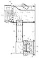
次に本発明に係る葉たばこ作業台の湿式集塵装置の一実施形態について、図面を参照して説明する。図1ないし図3において、符号10はピッキング作業台(葉たばこ作業台)、符号30は吸引ダクト、符号40は湿式集塵機を示している。 Next, an embodiment of a wet dust collector for a leaf tobacco working table according to the present invention will be described with reference to the drawings. 1 to 3,
ピッキング作業台10は、四隅にキャスター付きの脚部11を備えると共に、葉たばこの乾葉Aを葉たばこ吊り具1ごと上面に載置可能な作業テーブル12を備えている。作業テーブル12は、床面Gに対し水平で平面視して長方形状の枠体13と、枠体13の内側に回転自在に軸支され、隙間Sを介して互いに平行に配置された多数本の長尺な円筒パイプ14とから構成されている。円筒パイプ14は、回転自在とされることで、その隙間Sからピッキングされた不良乾葉等を引っ掛けることなく床面Gに落下させることができる。 The picking work table 10 includes
作業テーブル12の下部には、作業テーブル12の下部空間の四方を囲む集塵フード15が取付けられている。集塵フード15は、可撓性のあるシート素材、例えば透明ビニールから構成されると共に、同透明ビニールを作業テーブル12の四方から床面Gまで垂らすことにより、集塵フード15が形成されている。作業テーブル12の後部側の脚部11間には、葉たばこ吊り具1の針ラック2を一時保管する受けラック16が取付けられている。受けラック16側に位置する透明ビニール部分は、受けラック16との干渉を避けるために水平バー17により脚部11の内側に寄せられている。 A
作業テーブル12の前方下部には、枠体13から吊下げられた取付板18を介して送風機(送風手段)19が設けられている。この送風機19は、吸引ダクト30へ向けて集塵フード15内の空気を送出するもので、円筒ケーシング20が集塵フード15の前面開口部15aから前方に突出し、フレキシブルダクトからなる吸引ダクト30の一端に環状バンド31で接続されている。送風機19のモータ21でファン22を回転駆動させると、作業テーブル12の円筒パイプ14,14間の隙間Sから、ピッキング作業中に発生する粉塵、葉たばこ乾葉Aに混入、付着された異物が空気と共に吸引されて、集塵フード15内に一次的に集塵、捕集され、金属片などの比較的重量のある異物は床面Gに落下する一方、集塵フード15内の空気が粉塵等の比較的軽い異物と共に、吸引ダクト30へ向けて送出されるようになっている。 A blower (blower unit) 19 is provided at a lower front portion of the work table 12 via a mounting
湿式集塵機40は、集塵機本体41の、有頭筒状の上部ケーシング42内に送風機(吸引手段)43が設けられて、吸引ダクト30から吸込口44を通して上部ケーシング42内に空気を吸引すると共に、集塵機本体41の、有底筒状の下部ケーシング45底部に貯水槽46が設けられて、上部ケーシング42内に吸引した空気を貯水槽46内に案内し、その後に清浄空気を排気口47から集塵機本体41外の作業空間内へ排気するものである。送風機43は、上部ケーシング42内の中央で、下部ケーシング45底部の貯水槽46の直上に配置されている。上部ケーシング42の外面には、先端に吸込口44が形成されると共に、上部ケーシング42内に連通する円筒形の接続部48が横向きに取付けられている。同接続部48の先端部には吸引ダクト30の他端が環状のバンド31にて接続されている。 The
送風機43の出口にはオリフィス部49が設けられている。オリフィス部49は、送風機43のファン52の回転により吸込口44から上部ケーシング41内に吸引された空気を、オリフィス孔50の入口と出口の通過差圧(オリフィス効果)により、渦流を発生させながら貯水槽46の水面へ向け強く噴出するもので、上部ケーシング41の内周面に仕切り板51が取付けられると共に、仕切り板51の中央に、送風機43のファン52の外径D1よりも口径D2の小さいオリフィス孔50が形成されている。オリフィス部49の出口には、貯水槽46の水面近傍まで垂直下方に延びる整流ダクト53が取付けられている。整流ダクト53下端の空気吹出口54は貯水槽46の水面近傍に位置している。 An
有底筒状の下部ケーシング45は空気吹出口54を含む整流ダクト53を囲むように配置されている。下部ケーシング45の内部には、空気チャンバー室55が形成されると共に、空気チャンバー室55の底面から所定高さHまで水Wが貯えられ、空気チャンバー室55の下部に前記貯水槽46が形成されている。下部ケーシング45の内面と整流ダクト53の外面との間には、空気吹出口54から下向きに吹き出された空気の排気通路56が形成されている。空気吹出口54の周囲には、空気吹出口54から直下に吹き出された空気を、貯水槽46の水面に沿って水平方向に整流化して排気通路56の入口に案内する鍔状の整流板57が取付けられている。下部ケーシング45の内面の上端近くには、排気通路56の入口から排気通路56内を下部ケーシング45の内面に沿って上向きに流れる空気を、S字状に屈曲させる整流板58が取付けられている。 The bottomed cylindrical
下部ケーシング45の上側には、有頭筒状の排気フード59が配置されている。この排気フード59は、整流板58によりS字状に屈曲された排気通路56内の空気を下部ケーシング45の外面に沿って逆U字状に屈曲させ、排気口47から下向きに排気するようになっている。なお、前記排気フード59は、図1に示すように、上部ケーシング42に対して取付けられている。 A headed
以上の湿式集塵機40は、キャスター61付きのベース60を備えており、図2および図3に示すように、排気フード59および上部ケーシング42が、周上に配設された4本の支柱62を介してベース60上に支持されると共に、下部ケーシング43がベース60上に載置されている。湿式集塵機40は、キャスター61により、自由に移動できるようになっている。 The above
次に、図4を参照して、葉たばこ作業台の湿式集塵装置の運転方法と作用を説明する。まず、ピッキング作業台10の近傍に湿式集塵機40を移動し、吸引ダクト30でこれらを接続する。ピッキング作業台10の作業テーブル12上に葉たばこ乾葉Aを葉たばこ吊り具1ごと載置し、図示しない電源を入れて、2台の送風機19、送風機43の各ファンを駆動させる。ピッキング作業台10側の送風機19により作業テーブル12の円筒パイプ14の隙間Sから空気が吸引され、吸引ダクト30内へ送出される。吸引ダクト30内へ送出された空気は、湿式集塵機40側の送風機43により吸込口44から上部ケーシング42内に吸引され、下向きとなって送風機43の円筒ケーシング内を通り、オリフィス部49のオリフィス孔50から強く噴出され、渦流となって空気吹出口54から直下の貯水槽46の水面に強く吹き付けられる。 Next, with reference to FIG. 4, the operation method and effect | action of the wet dust collector of a leaf tobacco working table are demonstrated. First, the
貯水槽46の水面は、強く吹き付けられた空気の風圧により水面が図4に示すように下がり、水面がリング状に波立つ状態となる。これにより、水面の表面積が増大し、空気と水面との接触面積が増大する。水面と接触した空気は、整流板57、58により排気通路56をS字状に案内されて、排気口47から作業室内へ排気される。 The water surface of the
ピッキング作業に伴い発生する粉塵、葉たばこ乾葉Aに混入、付着した他の異物は、吸引される空気と共に作業テーブル12の隙間Sから吸引され、集塵フード15内に排出される。金属片など比較的重い異物は、集塵フード15内を自重で落下し、床面G上に貯留される。一方、粉塵やわき芽、ビニール片など比較的軽い異物は、集塵フード15内から、2台の送風機19、43により空気と共に、吸引ダクト30を介して湿式集塵機40内に吸引され、貯水槽46内に送られる。上記に述べたように、貯水槽46の水面は、オリフィス部49のオリフィス効果により、水面がリング状に波立つ状態となって、水面との接触面積が増大するから、粉塵その他の異物が効率よく連続的に接触させられ、貯水槽46内に集塵、捕集される。集塵、捕集された粉塵その他の異物は水面に浮遊する他、大部分が水没し、長期にわたり集塵能力、捕集能力が維持される。粉塵その他の異物が除去された後、清浄化された空気のみが排気口47から作業室内に排気される。 Dust generated during the picking operation and other foreign matter mixed in and attached to the dry tobacco A are sucked from the gap S of the work table 12 together with the sucked air and discharged into the
以上の実施形態では、葉たばこ乾葉Aのピッキング作業について説明したが、葉たばこ生葉の葉詰め作業にも適用できるのはもちろんである。また、ピッキング作業台10は、送風機19の吸引作用によって粉塵その他の異物を隙間Sから集塵フード15内に吸引する他、振動発生器によるピッキング作業台10の振動によって粉塵その他の異物を集塵フード15内に排出するようにしてもよい。さらに、葉たばこ作業台は、ピッキング作業台以外の作業台を含む概念であり、例えば専用の異物除去作業台であってもよい。 In the above embodiment, the picking operation of the leaf tobacco dry leaf A has been described, but it is needless to say that it can be applied to the leaf filling operation of fresh leaf tobacco. The picking work table 10 sucks dust and other foreign matters into the
本発明に係る葉たばこ作業台の湿式集塵装置は、葉たばこ作業台に付属して使用され、葉たばこのピッキング作業または葉詰め作業中に発生する粉塵やその他の葉たばこに混入、付着した異物を集塵、捕集する装置として利用可能である。また、作業室内の空気を清浄する装置としても利用可能である。 The wet dust collector of a leaf tobacco working table according to the present invention is used attached to the leaf tobacco working table, and collects dust generated during picking or leaf stuffing of leaf tobacco and other foreign matter mixed in and attached to the leaf tobacco. It can be used as a collecting device. It can also be used as a device for cleaning the air in the work chamber.
1 葉たばこの吊り具
2 針ラック
10 ピッキング作業台
11 脚部
12 作業テーブル
13 枠体
14 円筒パイプ
15 集塵フード
16 ラック受け
17 水平バー
18 取付板
19,43 送風機
20 円筒ケーシング
21 モータ
22,52 ファン
30 吸引ダクト
31 環状バンド
40 湿式集塵機
41 集塵機本体
42 上部ケーシング
44 吸込口
45 下部ケーシング
46 貯水槽
47 排気口
48 接続部
49 オリフィス部
50 オリフィス孔
51 仕切り板
53 整流ダクト
54 空気吹出口
55 空気チャンバー室
56 排気通路
57,58 整流板
59 排気フード
60 ベース
61 キャスター
62 支柱
A 葉たばこ乾葉
D1 送風機のファンの外径
D2 オリフィス部のオリフィス孔の口径
G 床面
S 隙間
W 水DESCRIPTION OF SYMBOLS 1 Leaf
Claims (6)
Translated fromJapanesePriority Applications (1)
| Application Number | Priority Date | Filing Date | Title |
|---|---|---|---|
| JP2007109808AJP2008263830A (en) | 2007-04-18 | 2007-04-18 | Wet-type dust collector of leaf tobacco workbench |
Applications Claiming Priority (1)
| Application Number | Priority Date | Filing Date | Title |
|---|---|---|---|
| JP2007109808AJP2008263830A (en) | 2007-04-18 | 2007-04-18 | Wet-type dust collector of leaf tobacco workbench |
Publications (1)
| Publication Number | Publication Date |
|---|---|
| JP2008263830Atrue JP2008263830A (en) | 2008-11-06 |
Family
ID=40044244
Family Applications (1)
| Application Number | Title | Priority Date | Filing Date |
|---|---|---|---|
| JP2007109808APendingJP2008263830A (en) | 2007-04-18 | 2007-04-18 | Wet-type dust collector of leaf tobacco workbench |
Country Status (1)
| Country | Link |
|---|---|
| JP (1) | JP2008263830A (en) |
Cited By (11)
| Publication number | Priority date | Publication date | Assignee | Title |
|---|---|---|---|---|
| CN110447947A (en)* | 2019-08-19 | 2019-11-15 | 江西中烟工业有限责任公司 | A kind of suction conveying device for tobacco leaf production processing |
| KR20210142648A (en)* | 2019-12-06 | 2021-11-25 | 프로리 시스템스 인코포레이티드 | Engineered actuators available for active cooling of electromechanical systems |
| US11705382B2 (en) | 2018-08-10 | 2023-07-18 | Frore Systems Inc. | Two-dimensional addessable array of piezoelectric MEMS-based active cooling devices |
| US11765863B2 (en) | 2020-10-02 | 2023-09-19 | Frore Systems Inc. | Active heat sink |
| US11796262B2 (en) | 2019-12-06 | 2023-10-24 | Frore Systems Inc. | Top chamber cavities for center-pinned actuators |
| US11802554B2 (en) | 2019-10-30 | 2023-10-31 | Frore Systems Inc. | MEMS-based airflow system having a vibrating fan element arrangement |
| US12029005B2 (en) | 2019-12-17 | 2024-07-02 | Frore Systems Inc. | MEMS-based cooling systems for closed and open devices |
| US12033917B2 (en) | 2019-12-17 | 2024-07-09 | Frore Systems Inc. | Airflow control in active cooling systems |
| US12089374B2 (en) | 2018-08-10 | 2024-09-10 | Frore Systems Inc. | MEMS-based active cooling systems |
| US12137540B2 (en) | 2019-12-06 | 2024-11-05 | Frore Systems Inc. | Centrally anchored MEMS-based active cooling systems |
| US12193192B2 (en) | 2019-12-06 | 2025-01-07 | Frore Systems Inc. | Cavities for center-pinned actuator cooling systems |
Citations (2)
| Publication number | Priority date | Publication date | Assignee | Title |
|---|---|---|---|---|
| JPS6155919U (en)* | 1984-09-17 | 1986-04-15 | ||
| JP2005095147A (en)* | 2004-06-09 | 2005-04-14 | Fulta Electric Machinery Co Ltd | Picking table for taking countermeasure against inclusion of foreign material |
- 2007
- 2007-04-18JPJP2007109808Apatent/JP2008263830A/enactivePending
Patent Citations (2)
| Publication number | Priority date | Publication date | Assignee | Title |
|---|---|---|---|---|
| JPS6155919U (en)* | 1984-09-17 | 1986-04-15 | ||
| JP2005095147A (en)* | 2004-06-09 | 2005-04-14 | Fulta Electric Machinery Co Ltd | Picking table for taking countermeasure against inclusion of foreign material |
Cited By (21)
| Publication number | Priority date | Publication date | Assignee | Title |
|---|---|---|---|---|
| US11830789B2 (en) | 2018-08-10 | 2023-11-28 | Frore Systems Inc. | Mobile phone and other compute device cooling architecture |
| US12089374B2 (en) | 2018-08-10 | 2024-09-10 | Frore Systems Inc. | MEMS-based active cooling systems |
| US11705382B2 (en) | 2018-08-10 | 2023-07-18 | Frore Systems Inc. | Two-dimensional addessable array of piezoelectric MEMS-based active cooling devices |
| US11710678B2 (en) | 2018-08-10 | 2023-07-25 | Frore Systems Inc. | Combined architecture for cooling devices |
| US11735496B2 (en) | 2018-08-10 | 2023-08-22 | Frore Systems Inc. | Piezoelectric MEMS-based active cooling for heat dissipation in compute devices |
| US11784109B2 (en) | 2018-08-10 | 2023-10-10 | Frore Systems Inc. | Method and system for driving piezoelectric MEMS-based active cooling devices |
| CN110447947A (en)* | 2019-08-19 | 2019-11-15 | 江西中烟工业有限责任公司 | A kind of suction conveying device for tobacco leaf production processing |
| US11802554B2 (en) | 2019-10-30 | 2023-10-31 | Frore Systems Inc. | MEMS-based airflow system having a vibrating fan element arrangement |
| US12137540B2 (en) | 2019-12-06 | 2024-11-05 | Frore Systems Inc. | Centrally anchored MEMS-based active cooling systems |
| US11796262B2 (en) | 2019-12-06 | 2023-10-24 | Frore Systems Inc. | Top chamber cavities for center-pinned actuators |
| KR20210142648A (en)* | 2019-12-06 | 2021-11-25 | 프로리 시스템스 인코포레이티드 | Engineered actuators available for active cooling of electromechanical systems |
| JP7397101B2 (en) | 2019-12-06 | 2023-12-12 | フロー・システムズ・インコーポレーテッド | Methods for cooling actuators, cooling systems and heat generating structures |
| JP2022534745A (en)* | 2019-12-06 | 2022-08-03 | フロー・システムズ・インコーポレーテッド | Improved Actuators Available in MEMS Active Coolers |
| KR102638828B1 (en)* | 2019-12-06 | 2024-02-22 | 프로리 시스템스 인코포레이티드 | Engineered actuators for use in active cooling of electromechanical systems |
| US12193192B2 (en) | 2019-12-06 | 2025-01-07 | Frore Systems Inc. | Cavities for center-pinned actuator cooling systems |
| US12274035B2 (en) | 2019-12-06 | 2025-04-08 | Frore Systems Inc. | Engineered actuators usable in MEMs active cooling devices |
| US12320595B2 (en) | 2019-12-06 | 2025-06-03 | Frore Systems Inc. | Top chamber cavities for center-pinned actuators |
| US12029005B2 (en) | 2019-12-17 | 2024-07-02 | Frore Systems Inc. | MEMS-based cooling systems for closed and open devices |
| US12033917B2 (en) | 2019-12-17 | 2024-07-09 | Frore Systems Inc. | Airflow control in active cooling systems |
| US11765863B2 (en) | 2020-10-02 | 2023-09-19 | Frore Systems Inc. | Active heat sink |
| US12167574B2 (en) | 2020-10-02 | 2024-12-10 | Frore Systems Inc. | Active heat sink |
Similar Documents
| Publication | Publication Date | Title |
|---|---|---|
| JP2008263830A (en) | Wet-type dust collector of leaf tobacco workbench | |
| US7282074B1 (en) | Auxiliary dust collection system | |
| US7247180B1 (en) | Silencer for dust collection system | |
| CN106955553A (en) | A kind of new polishing dust processing equipment | |
| CN107755152A (en) | A spray booth system with powder recovery structure | |
| JP2003205214A (en) | Method and device for removing dust | |
| CN104688135B (en) | A kind of accessory structure applied on dust catcher | |
| CN202087474U (en) | Water curtain type dustless paint spraying booth | |
| CN220093253U (en) | Side suction dust removing structure for band sawing machine | |
| CN209696586U (en) | A kind of deduster | |
| JP2003164718A (en) | Dust removal method and apparatus therefor | |
| CN101976030B (en) | Dust removal machine for laser drum powder box | |
| CN211886083U (en) | Electric automatization dust collector | |
| CN212039631U (en) | A dust-removing and dust-removing device for fruit shell food processing | |
| CN211439606U (en) | Dustproof device of sand blasting machine | |
| CN206911032U (en) | Filter cylinder of dust collector with dust removing device | |
| JP3093342U (en) | Industrial vacuum cleaner | |
| CN207657794U (en) | A kind of Automobile Service interlayer dust exhaust apparatus | |
| CN102793515A (en) | Cyclone dust collector flow channel structure | |
| CN219500914U (en) | A high-efficiency vacuum cleaner | |
| CN220214404U (en) | Air dust removal equipment for paper product manufacturing | |
| CN220724647U (en) | Environmental protection blanket dust removal platform | |
| CN114849392B (en) | Tobacco water-saving self-cleaning water mist dust removal device | |
| CN211420359U (en) | Galvanizing device for metal hinge processing | |
| CN210448493U (en) | Negative pressure dust removal device of polishing chamber |
Legal Events
| Date | Code | Title | Description |
|---|---|---|---|
| A621 | Written request for application examination | Free format text:JAPANESE INTERMEDIATE CODE: A621 Effective date:20100407 | |
| A131 | Notification of reasons for refusal | Effective date:20120606 Free format text:JAPANESE INTERMEDIATE CODE: A131 | |
| A02 | Decision of refusal | Effective date:20121031 Free format text:JAPANESE INTERMEDIATE CODE: A02 |