Movatterモバイル変換


[0]ホーム

URL:


JP2008255611A - Construction machinery - Google Patents

Construction machinery
Download PDF

Info

Publication number
JP2008255611A
JP2008255611AJP2007097429AJP2007097429AJP2008255611AJP 2008255611 AJP2008255611 AJP 2008255611AJP 2007097429 AJP2007097429 AJP 2007097429AJP 2007097429 AJP2007097429 AJP 2007097429AJP 2008255611 AJP2008255611 AJP 2008255611A
Authority
JP
Japan
Prior art keywords
counterweight
hydraulic cylinder
hydraulic
hydraulic pump
pressure oil
Prior art date
Legal status (The legal status is an assumption and is not a legal conclusion. Google has not performed a legal analysis and makes no representation as to the accuracy of the status listed.)
Pending
Application number
JP2007097429A
Other languages
Japanese (ja)
Inventor
Kentaro Tashiro
健太郎 田代
Current Assignee (The listed assignees may be inaccurate. Google has not performed a legal analysis and makes no representation or warranty as to the accuracy of the list.)
Hitachi Construction Machinery Co Ltd
Original Assignee
Hitachi Construction Machinery Co Ltd
Priority date (The priority date is an assumption and is not a legal conclusion. Google has not performed a legal analysis and makes no representation as to the accuracy of the date listed.)
Filing date
Publication date
Application filed by Hitachi Construction Machinery Co LtdfiledCriticalHitachi Construction Machinery Co Ltd
Priority to JP2007097429ApriorityCriticalpatent/JP2008255611A/en
Publication of JP2008255611ApublicationCriticalpatent/JP2008255611A/en
Pendinglegal-statusCriticalCurrent

Links

Images

Landscapes

Abstract

Translated fromJapanese

【課題】 昇降用の油圧シリンダに供給する圧油の流量を可変に制御し、カウンタウエイトの昇降速度が過度に速くなるのを抑えることができるようにする。
【解決手段】 油圧源を可変容量型の油圧ポンプ23により構成する。油圧ポンプ23からの圧油で油圧シリンダ16のロッド16Cを伸縮させ、これによりカウンタウエイト8を昇降駆動する。このときに、カウンタウエイト8の昇降位置を角度センサ22により検出する。そして、コントローラ34は、角度センサ22からの検出信号に従って油圧ポンプ23の傾転アクチュエータ25を駆動制御する。この結果、油圧ポンプ23による圧油の吐出量をカウンタウエイト8の昇降位置に応じて制御することができ、カウンタウエイト8の昇降速度が過度に速くなるの抑え、衝撃等の発生を防ぐことができる。
【選択図】 図5
PROBLEM TO BE SOLVED: To control the flow rate of pressure oil supplied to a hydraulic cylinder for raising and lowering variably so as to suppress an excessive increase in the lifting speed of a counterweight.
A hydraulic source is constituted by a variable displacement hydraulic pump. The rod 16C of the hydraulic cylinder 16 is expanded and contracted by the pressure oil from the hydraulic pump 23, thereby driving the counterweight 8 up and down. At this time, the elevation position of the counterweight 8 is detected by the angle sensor 22. Then, the controller 34 drives and controls the tilt actuator 25 of the hydraulic pump 23 according to the detection signal from the angle sensor 22. As a result, the discharge amount of the pressure oil by the hydraulic pump 23 can be controlled according to the raising / lowering position of the counterweight 8, and the raising / lowering speed of the counterweight 8 can be suppressed from being excessively increased, and the occurrence of an impact or the like can be prevented. it can.
[Selection] Figure 5

Description

Translated fromJapanese

本発明は、例えば油圧ショベル、油圧クレーン等の建設機械にカウンタウエイトを取付けたり、取外したりするときに好適に用いられるカウンタウエイト着脱装置を備えた建設機械に関する。  The present invention relates to a construction machine including a counterweight attaching / detaching device that is preferably used when a counterweight is attached to or detached from a construction machine such as a hydraulic excavator or a hydraulic crane.

一般に、油圧ショベル等の建設機械では、車体の前部側にブーム、アーム等の作業装置を設け、車体の後部側には、車体全体の重量バランスをとるためにカウンタウエイトを設ける構成としている。このようなカウンタウエイトは重量物であるため、例えばトレーラ等を用いて油圧ショベルを作業現場等に搬送するときには、カウンタウエイトを車体の後端側から取外し、車体側とは別々にカウンタウエイトを搬送することがある。  In general, a construction machine such as a hydraulic excavator is configured such that a working device such as a boom and an arm is provided on the front side of the vehicle body, and a counterweight is provided on the rear side of the vehicle body to balance the weight of the entire vehicle body. Since such a counterweight is heavy, for example, when a hydraulic excavator is transported to a work site using a trailer or the like, the counterweight is removed from the rear end side of the vehicle body, and the counterweight is transported separately from the vehicle body side. There are things to do.

また、車体の前部側に設ける作業装置にも、例えば軽掘削用、中掘削用、重掘削用等のように重量の異なる種々の作業装置があり、掘削作業の種類、内容等に応じては作業装置を取替えることがある。そして、作業装置を取替えるような場合には、それぞれの作業装置に対応させてカウンタウエイトも取替える必要が生じる。  There are also various work devices with different weights, such as for light excavation, for medium excavation, for heavy excavation, etc., depending on the type and content of excavation work. May change work equipment. When the work device is replaced, it is necessary to replace the counterweight corresponding to each work device.

このため、車体のフレームには、その後端側にカウンタウエイト着脱装置を設け、このカウンタウエイト着脱装置により、カウンタウエイトをフレームの後端側に自力で取付けたり、取外したりすることができる構成としたものが知られている(例えば、特許文献1参照)。  For this reason, the frame of the vehicle body is provided with a counterweight attaching / detaching device on the rear end side, and the counterweight attaching / detaching device allows the counterweight to be attached or detached by itself on the rear end side of the frame. Those are known (for example, see Patent Document 1).

特開平7−268908号公報Japanese Patent Laid-Open No. 7-268908

この種の従来技術によるカウンタウエイト着脱装置は、カウンタウエイトをフレーム上に昇降するため前記フレームの後端側に設けられた昇降機構を備えている。そして、この昇降機構は、前記フレームの後端に固定して設けられたブラケットと、基端側が該ブラケットに回動可能に取付けられ先端側が前記カウンタウエイトに吊下げ金具等を介して連結される回動アームと、該回動アームを上,下に回動するため前記ブラケットと回動アームとの間に設けられた昇降用の油圧シリンダとにより構成されている。  This type of prior art counterweight attaching / detaching device includes an elevating mechanism provided on the rear end side of the frame for elevating the counterweight on the frame. The elevating mechanism includes a bracket fixed to the rear end of the frame, a base end side rotatably attached to the bracket, and a front end side connected to the counterweight via a hanging metal fitting or the like. The rotating arm and a hydraulic cylinder for raising and lowering provided between the bracket and the rotating arm for rotating the rotating arm up and down.

ここで、昇降用の油圧シリンダは、油圧源から圧油が供給されることによりロッドを伸縮させ、これに伴って前記回動アームを上,下に回動する。そして、回動アームが上向きに回動するときには、前記吊下げ金具を介して回動アームの先端側に連結されたカウンタウエイトを、車体の後部側に向けて持上げるように上昇させる。また、回動アームが下向きに回動するときには、例えば地面等に向けてカウンタウエイトを吊下げるように下降させるものである。  Here, the raising / lowering hydraulic cylinder expands / contracts the rod when pressure oil is supplied from a hydraulic source, and accordingly, the rotating arm rotates upward and downward. When the pivot arm pivots upward, the counterweight connected to the distal end side of the pivot arm via the hanging bracket is raised so as to be lifted toward the rear side of the vehicle body. Further, when the pivot arm pivots downward, for example, the counterweight is lowered so as to be suspended toward the ground or the like.

ところで、上述した従来技術では、例えば油圧シリンダのロッドを伸長させて回動アームを上向きに回動し、これによって、カウンタウエイトを車体の後部側に向け持上げるように上昇させるときに、カウンタウエイトの持上げ速度が速いと、重量物であるカウンタウエイトが車体フレームの後端側に衝突し、例えばフレームの一部が破損、損傷されるという問題がある。  By the way, in the above-described prior art, for example, when the counterweight is raised to lift the counterweight toward the rear side of the vehicle body by, for example, extending the rod of the hydraulic cylinder and pivoting the pivot arm upward, When the lifting speed is high, the heavy weight counterweight collides with the rear end side of the vehicle body frame, and there is a problem that, for example, a part of the frame is broken or damaged.

即ち、重量物であるカウンタウエイトは、前記油圧シリンダにより回動アームを介して持上げるときに、非常に大きな慣性力が発生する。このため、不慣れなオペレータ等が油圧シリンダを駆動操作すると、カウンタウエイトの持上げ速度が過度に速くなることがある。  That is, the counterweight, which is a heavy object, generates a very large inertia force when it is lifted by the hydraulic cylinder via the rotating arm. For this reason, when an unfamiliar operator or the like drives and operates the hydraulic cylinder, the lifting speed of the counterweight may be excessively increased.

そして、カウンタウエイトが速い速度で持上げられると、その慣性力で車体フレームの後端側に強く衝突してしまい、例えば車体のフレームやカバーの一部が破損、損傷されるという問題が生じている。また、カウンタウエイトを地面等に向けて吊り降ろす場合にも、下降速度が速くなって衝撃が発生し易いという問題がある。  When the counterweight is lifted at a high speed, the inertial force strongly collides with the rear end side of the vehicle body frame, causing a problem that, for example, a part of the vehicle body frame or cover is broken or damaged. . In addition, even when the counterweight is suspended toward the ground or the like, there is a problem that the descent speed is increased and an impact is easily generated.

本発明は上述した従来技術の問題に鑑みなされたもので、本発明の目的は、油圧源から昇降用の油圧シリンダに供給する圧油の流量を可変に制御し、これによって、カウンタウエイトの昇降速度が過度に速くなるのを抑え、車体のフレームに対するカウンタウエイトの取付け、取外し作業を円滑に行うことができるようにした建設機械を提供することにある。  The present invention has been made in view of the above-described problems of the prior art, and an object of the present invention is to variably control the flow rate of pressure oil supplied from a hydraulic source to a lifting hydraulic cylinder, thereby raising and lowering the counterweight. It is an object of the present invention to provide a construction machine that can suppress the speed from becoming excessively high and can smoothly attach and remove a counterweight to / from a vehicle body frame.

上述した課題を解決するために本発明は、作業装置が設けられた車体と、前記作業装置に対する該車体の重量バランスをとるため該車体のフレームに着脱可能に設けられるカウンタウエイトと、前記フレームに設けられ該カウンタウエイトをフレームに対して取付け、取外しするときに、油圧シリンダを用いて該カウンタウエイトを上,下に昇降させるカウンタウエイト昇降機構と、該カウンタウエイト昇降機構の油圧シリンダに圧油を供給する油圧源とを備えてなる建設機械に適用される。  In order to solve the above-described problems, the present invention provides a vehicle body provided with a working device, a counterweight detachably provided on the frame of the vehicle body to balance the weight of the vehicle body with respect to the working device, and the frame. A counterweight lifting mechanism that lifts and lowers the counterweight using a hydraulic cylinder when attaching and removing the counterweight to and from the frame, and pressure oil to the hydraulic cylinder of the counterweight lifting mechanism The present invention is applied to a construction machine having a hydraulic pressure supply.

そして、請求項1の発明が採用する構成の特徴は、前記油圧源は、可変容量型の油圧ポンプにより構成し、該可変容量型の油圧ポンプは、前記油圧シリンダによってカウンタウエイトを昇降駆動するときに、該カウンタウエイトの昇降位置に従って圧油の吐出量を可変に制御する構成としたことにある。  According to the first aspect of the present invention, the hydraulic source is constituted by a variable displacement hydraulic pump, and the variable displacement hydraulic pump moves the counterweight up and down by the hydraulic cylinder. In addition, the discharge amount of the pressure oil is variably controlled according to the lift position of the counterweight.

また、請求項2の発明は、前記カウンタウエイトの昇降位置を検出する位置検出手段と、該位置検出手段からの検出信号に従って前記油圧ポンプの容量可変アクチュエータを駆動制御する制御手段とを備えてなる構成としている。  According to a second aspect of the present invention, there is provided position detecting means for detecting the raising / lowering position of the counterweight, and control means for drivingly controlling the variable displacement actuator of the hydraulic pump in accordance with a detection signal from the position detecting means. It is configured.

また、請求項3の発明によると、前記カウンタウエイト昇降機構は、前記車体のフレームに固定して設けられたブラケットと、基端側が該ブラケットに回動可能に取付けられ先端側が前記カウンタウエイトに連結される回動アームと、前記油圧ポンプからの圧油で伸縮されることにより該回動アームを上,下方向に回動して前記カウンタウエイトを昇降させる前記油圧シリンダとを含んで構成し、前記回動アームまたは油圧シリンダの回動部位には、前記カウンタウエイトの昇降位置を検出する位置検出手段を設ける構成としている。  According to a third aspect of the invention, the counterweight lifting mechanism includes a bracket fixed to the frame of the vehicle body, a base end side rotatably attached to the bracket, and a distal end side connected to the counterweight. And a hydraulic arm that moves the rotary arm up and down to raise and lower the counterweight by being expanded and contracted by pressure oil from the hydraulic pump. A position detecting means for detecting the raising / lowering position of the counterweight is provided at the rotating part of the rotating arm or the hydraulic cylinder.

さらに、請求項4の発明によると、前記位置検出手段は、前記油圧ポンプから油圧シリンダに供給する圧油の圧力を検出する圧力センサにより構成している。  According to a fourth aspect of the present invention, the position detecting means comprises a pressure sensor that detects the pressure of the pressure oil supplied from the hydraulic pump to the hydraulic cylinder.

上述の如く、請求項1に記載の発明によれば、油圧源を可変容量型の油圧ポンプにより構成し、該可変容量型の油圧ポンプは、油圧シリンダによりカウンタウエイトを昇降駆動するときに、該カウンタウエイトの昇降位置に従って圧油の吐出量を可変に制御する構成としているので、例えばカウンタウエイトを車体の後部側に持上げるように上昇させるときには、カウンタウエイトがフレームの後端に近付くに従って圧油の吐出量を小さく抑えることができる。これによって、油圧シリンダの速度を遅くすることができ、カウンタウエイトの持上げ速度を低く抑えて、重量物であるカウンタウエイトが車体のフレーム側に衝突するのを防ぐことができる。  As described above, according to the first aspect of the present invention, the hydraulic source is constituted by a variable displacement hydraulic pump, and when the variable displacement hydraulic pump drives the counterweight up and down by the hydraulic cylinder, Since the discharge amount of the pressure oil is variably controlled according to the lift position of the counterweight, for example, when the counterweight is lifted to be lifted to the rear side of the vehicle body, the pressure oil is increased as the counterweight approaches the rear end of the frame. Can be kept small. As a result, the speed of the hydraulic cylinder can be reduced, the lifting speed of the counterweight can be kept low, and the heavy weight of the counterweight can be prevented from colliding with the frame side of the vehicle body.

従って、油圧シリンダのロッドを伸縮させてカウンタウエイトを昇降駆動するときに、油圧ポンプの吐出量を可変に制御することにより、カウンタウエイトの昇降速度が過度に速くなるのを抑えることができ、車体のフレームに対するカウンタウエイトの取付け、取外し作業を円滑に行うことができる。  Therefore, when the counterweight is driven to move up and down by extending and retracting the rod of the hydraulic cylinder, it is possible to prevent the counterweight from being excessively increased by controlling the discharge amount of the hydraulic pump variably. The counterweight can be attached to and detached from the frame smoothly.

また、請求項2に記載の発明は、油圧シリンダのロッドを伸縮させてカウンタウエイトを昇降駆動するときに、カウンタウエイトの昇降位置を位置検出手段により検出することができ、制御手段は該位置検出手段からの検出信号に従って前記油圧ポンプの容量可変アクチュエータを駆動制御することにより、油圧ポンプから吐出される圧油の流量をカウンタウエイトの昇降位置に従って可変に制御することができる。  According to the second aspect of the present invention, when the counterweight is moved up and down by extending and contracting the rod of the hydraulic cylinder, the position detecting means can detect the position of the counterweight, and the control means can detect the position. By driving and controlling the variable displacement actuator of the hydraulic pump according to the detection signal from the means, the flow rate of the pressure oil discharged from the hydraulic pump can be variably controlled according to the lift position of the counterweight.

また、請求項3に記載の発明によれば、カウンタウエイト昇降機構を、車体のフレームに固定して設けられたブラケットと、油圧シリンダと、前記ブラケットに回動可能に取付けられ油圧シリンダの伸縮に従って上,下に回動される回動アームとにより構成することができ、前記回動アームまたは油圧シリンダの回動部位には、前記カウンタウエイトの昇降位置を検出する位置検出手段を設けることができる。  According to the third aspect of the present invention, the counterweight lifting mechanism is provided with a bracket fixed to the frame of the vehicle body, a hydraulic cylinder, and a pivotally attached to the bracket according to the expansion and contraction of the hydraulic cylinder. It can be constituted by a pivot arm that pivots up and down, and a position detection means for detecting the raising / lowering position of the counterweight can be provided at the pivot part of the pivot arm or the hydraulic cylinder. .

さらに、請求項4に記載の発明によれば、油圧ポンプから油圧シリンダに供給する圧油の圧力を圧力センサで検出することにより、検出圧力の変化からカウンタウエイトの昇降位置を求めることができ、この位置検出の結果から油圧ポンプの吐出量を可変に制御することができる。そして、この場合には、例えば油圧シリンダに接続される主管路の途中に圧力センサを設けることができ、その取付作業性、組立性等を向上することができる。  Furthermore, according to the invention described inclaim 4, by detecting the pressure of the pressure oil supplied from the hydraulic pump to the hydraulic cylinder by the pressure sensor, the raising / lowering position of the counterweight can be obtained from the change in the detected pressure, The discharge amount of the hydraulic pump can be variably controlled from the result of this position detection. In this case, for example, a pressure sensor can be provided in the middle of the main pipeline connected to the hydraulic cylinder, and its mounting workability, assembling performance, etc. can be improved.

以下、本発明の実施の形態による建設機械を、所謂標準機と呼ばれる中型の油圧ショベルに適用した場合を例に挙げて、添付図面を参照して詳細に説明する。  Hereinafter, a construction machine according to an embodiment of the present invention will be described in detail with reference to the accompanying drawings, taking as an example a case where the construction machine is applied to a medium-sized hydraulic excavator called a so-called standard machine.

ここで、図1ないし図8は本発明の第1の実施の形態を示している。図中、1は建設機械としての油圧ショベルで、該油圧ショベル1は、自走可能な下部走行体2と、該下部走行体2上に旋回可能に搭載され、下部走行体2と共に油圧ショベル1の車体を構成する上部旋回体3と、後述の作業装置7とにより大略構成されている。  Here, FIG. 1 to FIG. 8 show a first embodiment of the present invention. In the figure,reference numeral 1 denotes a hydraulic excavator as a construction machine. Thehydraulic excavator 1 is mounted on a self-propelled lower travelingbody 2 and on the lower travelingbody 2 so as to be able to turn. The upper revolvingbody 3 constituting the vehicle body and a work device 7 described later are roughly constituted.

4は上部旋回体3のベースフレームを構成する旋回フレームで、該旋回フレーム4は、複数の鋼板等を溶接することにより形成された頑丈な支持構造体として構成されている。そして、旋回フレーム4上には、その前部側に運転室を画成するキャブ5が設けられ、該キャブ5の後側には、例えばエンジン(図示せず)、後述の油圧ポンプ23等を内部に収容する建屋カバー6等が設けられている。  Reference numeral 4 denotes a revolving frame that constitutes a base frame of the upper revolvingstructure 3, and the revolvingframe 4 is configured as a sturdy support structure formed by welding a plurality of steel plates or the like. On the revolvingframe 4, a cab 5 that defines a cab is provided on the front side thereof, and on the rear side of the cab 5, for example, an engine (not shown), ahydraulic pump 23 described later, and the like are provided. The building cover 6 etc. accommodated in the inside are provided.

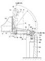
また、旋回フレーム4の後端側には、図3、図4に示す如くウエイト取付板4Aが設けられ、該ウエイト取付板4Aは、高い剛性をもった鋼板等の板材を旋回フレーム4の後端側に溶接等の手段で固着したものである。ここで、ウエイト取付板4Aは、後述のカウンタウエイト8にほぼ対応する寸法をもって旋回フレーム4の幅方向(左右方向)に延びている。そして、後述のカウンタウエイト8は、ウエイト取付板4Aに衝合するように取付けられ、この状態で旋回フレーム4の後端側に複数の長尺ボルト(図示せず)等を介して着脱可能に位置決めされるものである。  Further, as shown in FIGS. 3 and 4, aweight mounting plate 4 </ b> A is provided on the rear end side of theswivel frame 4, and theweight mounting plate 4 </ b> A uses a plate material such as a steel plate having high rigidity as the rear of theswivel frame 4. It is fixed to the end side by means such as welding. Here, theweight attachment plate 4A extends in the width direction (left-right direction) of therevolving frame 4 with a dimension substantially corresponding to acounterweight 8 described later. Acounterweight 8, which will be described later, is mounted so as to abut against theweight mounting plate 4A, and can be attached to and detached from the rear end side of the revolvingframe 4 via a plurality of long bolts (not shown) in this state. It is to be positioned.

7は旋回フレーム4の前側に設けられた作業装置で、該作業装置7は、例えばブーム7Aの基端側が旋回フレーム4の前部に俯仰動可能に取付けられ、ブーム7Aの先端側には、アーム7Bを介して作業具としてのバケット7Cが回動可能に設けられている。そして、作業装置7は、例えば土砂等の掘削作業を先端側のバケット7C等を用いて行うものである。  7 is a working device provided on the front side of theswing frame 4, and the work device 7 is attached, for example, such that the base end side of the boom 7 </ b> A can be moved up and down on the front portion of theswing frame 4. Abucket 7C as a work tool is rotatably provided via thearm 7B. The work device 7 performs excavation work such as earth and sand using thebucket 7C on the front end side.

8は旋回フレーム4の後端側に着脱可能に設けられるカウンタウエイトで、該カウンタウエイト8は、前部側の作業装置7に対して上部旋回体3全体の重量バランスをとるものである。ここで、カウンタウエイト8には、その幅方向(左右方向)の中間となる位置に、図3に示す如く凹窪部8Aが形成され、この凹窪部8Aは、カウンタウエイト8の前面側で、旋回フレーム4のウエイト取付板4Aと対向配置されるものである。  Acounterweight 8 is detachably provided on the rear end side of theswing frame 4, and thecounterweight 8 balances the weight of the entireupper swing body 3 with respect to the work device 7 on the front side. Here, thecounterweight 8 is formed with arecessed portion 8A at a middle position in the width direction (left-right direction) as shown in FIG. 3, and thisrecessed portion 8A is formed on the front side of thecounterweight 8. Theweight mounting plate 4 </ b> A of theswivel frame 4 is disposed to face the rotatingframe 4.

そして、凹窪部8Aは、カウンタウエイト8をウエイト取付板4Aに衝合させるときに、カウンタウエイト8が後述の昇降機構10に突き当るのを防止し、この昇降機構10を凹窪部8Aの内側に収容できる構造となっている。また、カウンタウエイト8には、凹窪部8Aの上部側に一対の取付板8B,8Bが溶接またはボルト等の手段を用いて一体的に設けられている。そして、該各取付板8Bには、後述の吊り金具15が支持ピン15B等を介して着脱可能に取付けられるものである。  The recessedportion 8A prevents thecounterweight 8 from striking alifting mechanism 10 described later when thecounterweight 8 is brought into contact with theweight mounting plate 4A. It has a structure that can be accommodated inside. Thecounterweight 8 is integrally provided with a pair of mountingplates 8B, 8B on the upper side of the recessedportion 8A using means such as welding or bolts. A suspension fitting 15 described later is detachably attached to eachattachment plate 8B via asupport pin 15B or the like.

10は本実施の形態で採用したカウンタウエイト昇降機構で、該カウンタウエイト昇降機構10は、後述のブラケット11、回動アーム12および油圧シリンダ16を含んで構成されている。そして、カウンタウエイト昇降機構10は、図3、図4に示す如く油圧シリンダ16を伸縮動作することにより、旋回フレーム4の後端側でカウンタウエイト8を吊上げ、吊下げするものである。  Reference numeral 10 denotes a counterweight raising / lowering mechanism employed in the present embodiment. The counterweight raising / loweringmechanism 10 includes abracket 11, arotating arm 12, and ahydraulic cylinder 16 which will be described later. Thecounterweight lifting mechanism 10 lifts and suspends thecounterweight 8 on the rear end side of theturning frame 4 by extending and contracting thehydraulic cylinder 16 as shown in FIGS.

11は旋回フレーム4の後端側にウエイト取付板4Aと共に溶接等の手段で一体化して設けられたブラケットで、該ブラケット11は、図2に示す如く後述の油圧シリンダ16を左,右両側から挟むようにウエイト取付板4Aに設けられた左,右一対の第1ブラケット板11A,11Aと、該第1ブラケット板11Aとの間で後述の回動アーム12をスペーサ21等を介して挟むようにウエイト取付板4Aに設けられた左,右方向外側の第2ブラケット板11B,11Bとにより構成されている。  Reference numeral 11 denotes a bracket integrally provided on the rear end side of theswivel frame 4 by means such as welding together with theweight mounting plate 4A. Thebracket 11 attaches ahydraulic cylinder 16 described later from both the left and right sides as shown in FIG. A pair of left and rightfirst bracket plates 11A, 11A provided on theweight mounting plate 4A so as to be sandwiched, and arotating arm 12 described later are sandwiched between thefirst bracket plate 11A via aspacer 21 or the like. The left and right outersecond bracket plates 11B and 11B provided on theweight mounting plate 4A.

ここで、これらの第1,第2ブラケット板11A,11Bは、それぞれウエイト取付板4Aから後方に向け略三角形状をなして突出している。そして、第1ブラケット板11A,11Aは、後述する油圧シリンダ16の基端側を回動可能に支持し、第1ブラケット板11Aと第2ブラケット板11Bは、後述する回動アーム12の基端側を回動可能に支持するものである。  Here, each of the first andsecond bracket plates 11A and 11B protrudes rearward from theweight mounting plate 4A in a substantially triangular shape. Thefirst bracket plates 11A and 11A rotatably support a proximal end side of ahydraulic cylinder 16 described later, and thefirst bracket plate 11A and thesecond bracket plate 11B are proximal ends of arotating arm 12 described later. The side is rotatably supported.

12,12はカウンタウエイト昇降機構10の一部を構成する左,右一対の回動アームで、該各回動アーム12は、その基端側がブラケット板11A,11B間に配設され、該ブラケット板11A,11Bに対しそれぞれ連結ピン13等を介して回動可能にピン結合されている。そして、回動アーム12は、図3に示す如く、例えばカウンタウエイト8の高さ寸法に対応する長さ寸法を有し、その先端側には略三角形状をなす張出部12Aが一体形成されている。  Reference numerals 12 and 12 denote a pair of left and right rotating arms constituting a part of thecounterweight lifting mechanism 10, and each of the rotatingarms 12 has a proximal end disposed between thebracket plates 11A and 11B. 11A and 11B are respectively pin-coupled so as to be rotatable via a connectingpin 13 or the like. As shown in FIG. 3, therotating arm 12 has, for example, a length corresponding to the height of thecounterweight 8, and a protrudingportion 12A having a substantially triangular shape is integrally formed on the tip side thereof. ing.

14は各回動アーム12の張出部12Aに設けられた連結バーで、この連結バー14は、図2に示す如く各回動アーム12の張出部12Aを左,右方向に貫通して延び、左,右の回動アーム12,12を張出部12Aの位置で一体的に連結している。そして、連結バー14の両端側は、左,右の支承部14A,14Aとなり、該各支承部14Aには、カウンタウエイト8用の吊り金具15,15がそれぞれ取付けられている。  14 is a connecting bar provided on the overhangingportion 12A of eachrotating arm 12, and this connectingbar 14 extends through the overhangingportion 12A of eachrotating arm 12 in the left and right directions as shown in FIG. The left and rightrotating arms 12 and 12 are integrally connected at the position of the overhangingportion 12A. The both ends of the connectingbar 14 are left andright support portions 14A and 14A, andsuspension brackets 15 and 15 for thecounterweight 8 are respectively attached to thesupport portions 14A.

ここで、各吊り金具15は、その上端側が調整ボルト15A等を介して連結バー14の支承部14Aに取付けられ、吊り金具15の下端側には、支持ピン15Bを介してカウンタウエイト8の各取付板8Bが連結されるものである。これにより、回動アーム12の先端側(張出部12A)には、連結バー14と吊り金具15を介してカウンタウエイト8が図3、図4に示す如く吊下げられた状態に保持される。  Here, the upper end side of each suspension fitting 15 is attached to thesupport portion 14A of the connectingbar 14 via anadjustment bolt 15A and the like, and the lower end side of the suspension fitting 15 is attached to each of thecounterweights 8 via asupport pin 15B. Theattachment plate 8B is connected. As a result, thecounterweight 8 is held in a suspended state on the distal end side (the overhangingportion 12A) of therotating arm 12 via the connectingbar 14 and the suspension fitting 15 as shown in FIGS. .

この場合、吊り金具15の調整ボルト15Aは、例えばレンチ等の工具(図示せず)を用いて適宜に回動操作され、これにより吊り金具15は、連結バー14の支承部14Aに対して上,下に相対移動する。この結果、カウンタウエイト8は、回動アーム12に対して高さ位置の調整が行われるものである。  In this case, theadjustment bolt 15 </ b> A of the hangingbracket 15 is appropriately rotated using a tool (not shown) such as a wrench, so that the hangingbracket 15 is raised with respect to thesupport portion 14 </ b> A of the connectingbar 14. , Move down relative. As a result, the height of thecounterweight 8 is adjusted with respect to therotating arm 12.

16は各回動アーム12を上,下に回動させる昇降用の油圧シリンダで、該油圧シリンダ16は、図2〜図4に示す如く、チューブ16Aと、該チューブ16A内に摺動可能に挿嵌され、チューブ16A内に2つの油室A,Bを画成したピストン16B(図5参照)と、基端側がピストン16Bに固着され、先端側がチューブ16A外に突出したロッド16Cとにより構成されている。この場合、チューブ16A内の油室Aは、油圧シリンダ16のロッド16C側に位置し、油室Bはチューブ16Aのボトム側に位置するものである。  Reference numeral 16 denotes a hydraulic cylinder for raising and lowering eachrotary arm 12 up and down. Thehydraulic cylinder 16 is inserted into atube 16A and slidable in thetube 16A as shown in FIGS. It is configured by apiston 16B (see FIG. 5) that is fitted and defines two oil chambers A and B in thetube 16A, and arod 16C whose proximal end is fixed to thepiston 16B and whose distal end protrudes outside thetube 16A. ing. In this case, the oil chamber A in thetube 16A is located on therod 16C side of thehydraulic cylinder 16, and the oil chamber B is located on the bottom side of thetube 16A.

そして、油圧シリンダ16は、図2に示すように、チューブ16Aの基端側が第1ブラケット板11A,11A間にスペーサ17,17を介して配設され、左右方向に延びた連結ピン18により第1ブラケット板11A間に回動可能にピン結合されている。また、油圧シリンダ16のロッド16Cは、その突出端側が各回動アーム12の先端側にスペーサ19,19を介して配設され、左右方向に延びた連結ピン20により各回動アーム12の先端側に回動可能にピン結合されている。  As shown in FIG. 2, in thehydraulic cylinder 16, the proximal end side of thetube 16A is disposed between thefirst bracket plates 11A and 11A viaspacers 17 and 17, and is connected by a connectingpin 18 extending in the left-right direction. A pin is rotatably connected between thebracket plates 11A. Further, therod 16C of thehydraulic cylinder 16 has a protruding end side disposed on the front end side of eachrotary arm 12 viaspacers 19 and 19, and is connected to the front end side of eachrotary arm 12 by a connectingpin 20 extending in the left-right direction. It is pin-coupled so that it can rotate.

ここで、油圧シリンダ16は、後述の油圧ポンプ23から油室A,B(図5参照)内に圧油が給排されることにより、ロッド16Cをチューブ16Aから伸,縮させる。そして、カウンタウエイト昇降機構10の回動アーム12は、油圧シリンダ16の伸縮動作に伴って図3、図4に示す如く連結ピン13を中心として上,下に回動される。これにより回動アーム12は、吊り金具15等を介してカウンタウエイト8を吊上げたり、吊下げたりするものである。  Here, thehydraulic cylinder 16 extends and contracts therod 16 </ b> C from thetube 16 </ b> A by supplying and discharging pressure oil into the oil chambers A and B (see FIG. 5) from ahydraulic pump 23 described later. Thepivot arm 12 of thecounterweight lifting mechanism 10 is pivoted up and down about the connectingpin 13 as shown in FIGS. 3 and 4 as thehydraulic cylinder 16 expands and contracts. Thereby, therotating arm 12 lifts or suspends thecounterweight 8 via the hanging metal fitting 15 or the like.

21,21は各回動アーム12の基端側に設けられた左,右のスペーサで、該各スペーサ21は、図2に示すように連結ピン13を介して回動アーム12の基端側と第2ブラケット板11Bとの間に介挿されている。そして、スペーサ21は、回動アーム12の基端側がブラケット板11A,11Bに対してガタ付くのを抑えると共に、回動アーム12の円滑な動きを補償するものである。  21 and 21 are left and right spacers provided on the base end side of eachrotary arm 12, and eachspacer 21 is connected to the base end side of therotary arm 12 via a connectingpin 13 as shown in FIG. It is inserted between thesecond bracket plate 11B. Thespacer 21 prevents the base end side of therotating arm 12 from rattling with respect to thebracket plates 11A and 11B, and compensates for the smooth movement of therotating arm 12.

22は本実施の形態で採用した位置検出手段としての角度センサで、該角度センサ22は、例えば回動アーム12の基端側に配置された連結ピン13、スペーサ21等に付設されるものである。そして、この角度センサ22は、カウンタウエイト8の昇降位置を検出する位置検出手段を構成し、回動アーム12の回動位置(昇降位置)を、図5中に示すように回動角θx として検出するものである。  Reference numeral 22 denotes an angle sensor as position detecting means employed in the present embodiment. Theangle sensor 22 is attached to, for example, the connectingpin 13 and thespacer 21 arranged on the proximal end side of therotating arm 12. is there. Theangle sensor 22 constitutes position detecting means for detecting the raising / lowering position of thecounterweight 8, and the turning position (elevating position) of the turningarm 12 is set as a turning angle θx as shown in FIG. It is to detect.

この場合、回動角θx は、カウンタウエイト8が図4に実線で示す如く地面に接地している状態で最小角θ0 (例えば、θ0 =0)となる。そして、カウンタウエイト8が図3に実線で示す如くウエイト取付板4Aに衝合する位置まで持上げられた状態で、回動角θx は最大角θa (例えば、θa =90〜100度)となるものである。  In this case, the rotation angle θx becomes the minimum angle θ0 (for example, θ0 = 0) when thecounterweight 8 is in contact with the ground as shown by the solid line in FIG. In the state where thecounterweight 8 is lifted to a position where it abuts against theweight mounting plate 4A as shown by the solid line in FIG. 3, the rotation angle θx becomes the maximum angle θa (for example, θa = 90 to 100 degrees). It is.

なお、位置検出手段を構成する角度センサ22は、前記連結ピン13、スペーサ21に付設する場合に限るものではなく、回動アーム12の回動部位に設けて、その回動動作(回動角)できるものであればよい。また、油圧シリンダ16の回動部位に同様な角度センサを設け、油圧シリンダ16の回動動作(回動角)からカウンタウエイト8の昇降位置を検出する構成としてもよいものである。  Theangle sensor 22 constituting the position detecting means is not limited to the case where theangle sensor 22 is attached to the connectingpin 13 and the spacer 21. ) Anything that can be done. In addition, a similar angle sensor may be provided at the rotating portion of thehydraulic cylinder 16 so that the raising / lowering position of thecounterweight 8 is detected from the rotating operation (rotating angle) of thehydraulic cylinder 16.

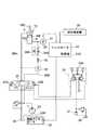
次に、23は図5に示すタンク24と共に油圧源を構成する可変容量型の油圧ポンプで、該油圧ポンプ23は、例えば斜板または弁板(図示せず)等からなる容量可変部23Aを有し、この容量可変部23Aは、後述の傾転アクチュエータ25で傾転駆動されることにより、油圧ポンプ23から吐出される圧油の吐出量を増減させるものである。そして、油圧ポンプ23は、上部旋回体3の建屋カバー6内に設けられた前記エンジンにより回転駆動され、油圧シリンダ16等に向けて圧油を供給するものである。  Next,reference numeral 23 denotes a variable displacement hydraulic pump that constitutes a hydraulic source together with thetank 24 shown in FIG. 5, and thehydraulic pump 23 includes adisplacement variable portion 23A made of, for example, a swash plate or a valve plate (not shown). Thecapacity variable portion 23A is configured to increase or decrease the discharge amount of the pressure oil discharged from thehydraulic pump 23 by being tilted by atilt actuator 25 described later. Thehydraulic pump 23 is rotationally driven by the engine provided in thebuilding cover 6 of theupper swing body 3 and supplies pressure oil toward thehydraulic cylinder 16 and the like.

25は油圧ポンプ23に付設された容量可変機構としての傾転アクチュエータで、該傾転アクチュエータ25は、油圧ポンプ23の容量可変部23Aを大傾転位置と小傾転位置との間で可変に傾転駆動する。これにより、油圧ポンプ23から吐出される圧油の流量(吐出量)は、容量可変部23Aが小傾転位置となったときに最小流量となり、大傾転位置となったときに最大流量となるように増減されるものである。  Reference numeral 25 denotes a tilt actuator as a capacity variable mechanism attached to thehydraulic pump 23. Thetilt actuator 25 can change thecapacity variable portion 23A of thehydraulic pump 23 between a large tilt position and a small tilt position. Tilt drive. As a result, the flow rate (discharge amount) of the pressure oil discharged from thehydraulic pump 23 becomes the minimum flow rate when thecapacity variable portion 23A is at the small tilt position, and the maximum flow rate when thecapacity variable portion 23A is at the large tilt position. It will be increased or decreased.

即ち、傾転アクチュエータ25は、後述するコントローラ34からの制御信号に従って油圧ポンプ23の容量可変部23Aを大傾転位置と小傾転位置との間で連続的に傾転駆動する。そして、容量可変部23Aが最小の傾転位置になると、油圧ポンプ23から吐出される圧油の流量は最小流量に抑えられ、これに伴って油圧シリンダ16の伸縮速度も遅い速度に抑えられるものである。  That is, the tiltingactuator 25 continuously drives thedisplacement variable portion 23A of thehydraulic pump 23 between the large tilting position and the small tilting position in accordance with a control signal from thecontroller 34 described later. When thecapacity variable portion 23A is at the minimum tilt position, the flow rate of the pressure oil discharged from thehydraulic pump 23 is suppressed to the minimum flow rate, and accordingly, the expansion / contraction speed of thehydraulic cylinder 16 is also suppressed to a slow speed. It is.

26A,26Bは油圧シリンダ16と油圧ポンプ23,タンク24との間に設けられた一対の主管路で、該主管路26A,26Bは、油圧ポンプ23からの圧油を後述の方向制御弁27を介して油圧シリンダ16の油室A,Bに給排するものである。  26A and 26B are a pair of main pipes provided between thehydraulic cylinder 16, thehydraulic pump 23 and thetank 24. Themain pipes 26A and 26B send pressure oil from thehydraulic pump 23 to adirectional control valve 27 which will be described later. The oil chambers A and B of thehydraulic cylinder 16 are supplied to and discharged from.

27は油圧ポンプ23,タンク24と油圧シリンダ16との間に位置して主管路26A,26Bの途中に設けられた方向制御弁で、該方向制御弁27は、例えば左,右両側に油圧パイロット部27A,27Bを有し、該油圧パイロット部27A,27Bに供給されるパイロット圧に従って中立位置(イ)から左,右の切換位置(ロ),(ハ)に切換えられる。  Adirectional control valve 27 is located between thehydraulic pump 23, thetank 24 and thehydraulic cylinder 16 and is provided in the middle of themain pipelines 26A and 26B. Thedirectional control valve 27 is, for example, a hydraulic pilot on both the left and right sides. 27A and 27B, and is switched from the neutral position (A) to the left and right switching positions (B) and (C) according to the pilot pressure supplied to thehydraulic pilot units 27A and 27B.

そして、方向制御弁27は、中立位置(イ)から切換位置(ロ)に切換えられると、油圧ポンプ23からの圧油を主管路26Bを介して油圧シリンダ16の油室Bに供給し、油室A内の油液を主管路26A側からタンク24に向けて排出させる。これにより、油圧シリンダ16のロッド16Cは、チューブ16Aから突出するように伸長する。  When thedirectional control valve 27 is switched from the neutral position (A) to the switching position (B), the pressure oil from thehydraulic pump 23 is supplied to the oil chamber B of thehydraulic cylinder 16 through themain pipeline 26B. The oil liquid in the chamber A is discharged toward thetank 24 from themain pipeline 26A side. Thereby, therod 16C of thehydraulic cylinder 16 extends so as to protrude from thetube 16A.

一方、方向制御弁27が中立位置(イ)から切換位置(ハ)に切換えられたときには、油圧ポンプ23からの圧油が主管路26Aを介して油圧シリンダ16の油室Aに供給され、油室B内の油液が主管路26A側からタンク24に向けて排出される。これにより、油圧シリンダ16のロッド16Cは、チューブ16A内向けて縮小するように変位する。  On the other hand, when thedirectional control valve 27 is switched from the neutral position (A) to the switching position (C), the pressure oil from thehydraulic pump 23 is supplied to the oil chamber A of thehydraulic cylinder 16 via themain pipeline 26A. The oil liquid in the chamber B is discharged toward thetank 24 from themain pipeline 26A side. Thereby, therod 16C of thehydraulic cylinder 16 is displaced so as to shrink toward the inside of thetube 16A.

28は主管路26Bの途中に設けられたパイロット作動式チェック弁で、該チェック弁28は、例えば方向制御弁27が中立位置(イ)にある間は閉弁状態を保ち、油圧シリンダ16の油室Bから主管路26Bを通じて油液が漏出するのを抑える。これにより、チェック弁28は、油圧シリンダ16のロッド16Cがカウンタウエイト8からの荷重(自重)で縮小方向に変位してしまうのを防ぐものである。  Reference numeral 28 denotes a pilot operated check valve provided in the middle of themain pipeline 26B. Thecheck valve 28 keeps the valve closed while thedirectional control valve 27 is in the neutral position (A), for example. The oil liquid is prevented from leaking from the chamber B through themain pipeline 26B. Thereby, thecheck valve 28 prevents therod 16C of thehydraulic cylinder 16 from being displaced in the reduction direction by the load (self-weight) from thecounterweight 8.

一方、方向制御弁27が中立位置(イ)から切換位置(ロ)に切換えられたときには、例えば主管路26A側に供給される圧油がパイロット圧となってチェック弁28に供給される。これにより、チェック弁28は強制開弁され、油圧シリンダ16の油室Bから主管路26Bを通じて油液が排出されるのを許す。また、方向制御弁27が切換位置(ハ)に切換えられたときには、油圧ポンプ23から圧油を主管路26Bを介して油圧シリンダ16の油室B内に供給するようにチェック弁28は開弁されるものである。  On the other hand, when thedirectional control valve 27 is switched from the neutral position (A) to the switching position (B), for example, pressure oil supplied to themain line 26A side is supplied to thecheck valve 28 as a pilot pressure. As a result, thecheck valve 28 is forcibly opened to allow the oil liquid to be discharged from the oil chamber B of thehydraulic cylinder 16 through themain line 26B. When thedirectional control valve 27 is switched to the switching position (c), thecheck valve 28 is opened so that the hydraulic oil is supplied from thehydraulic pump 23 into the oil chamber B of thehydraulic cylinder 16 via themain pipeline 26B. It is what is done.

29は主管路26Bの途中に設けられたスローリターンバルブで、該スローリターンバルブ29は、油圧シリンダ16とチェック弁28との間に位置して主管路26Bの途中に設けられた逆止弁29Aと、該逆止弁29Aに対して並列接続された可変絞り弁29Bとにより構成されている。そして、スローリターンバルブ29は、油圧シリンダ16の油室B内に主管路26B側から圧油を供給するときに逆止弁29Aが開くことにより、圧油の流れを円滑にする。  Reference numeral 29 denotes a slow return valve provided in the middle of themain pipeline 26B. Theslow return valve 29 is located between thehydraulic cylinder 16 and thecheck valve 28 and is acheck valve 29A provided in the middle of themain pipeline 26B. And avariable throttle valve 29B connected in parallel to thecheck valve 29A. Theslow return valve 29 smoothes the flow of pressure oil by opening thecheck valve 29A when pressure oil is supplied into the oil chamber B of thehydraulic cylinder 16 from themain line 26B side.

しかし、油圧シリンダ16の油室Bから主管路26Bを通じて油液を排出するときには、スローリターンバルブ29の逆止弁29Aが閉弁し、このときの油液は可変絞り弁29Bを通じてタンク24側に排出される。このため、可変絞り弁29Bを流通する油液には絞り作用が与えられ、油圧シリンダ16のロッド16Cがチューブ16A内に向けて縮小する動作は、可変絞り弁29Bにより遅い速度に抑えられる。  However, when the oil liquid is discharged from the oil chamber B of thehydraulic cylinder 16 through themain line 26B, thecheck valve 29A of theslow return valve 29 is closed, and the oil liquid at this time passes to thetank 24 side through thevariable throttle valve 29B. Discharged. For this reason, the oil liquid flowing through thevariable throttle valve 29B is throttled, and the operation of therod 16C of thehydraulic cylinder 16 contracting into thetube 16A is suppressed to a slow speed by thevariable throttle valve 29B.

30はチェック弁28とスローリターンバルブ29の間に位置して主管路26Bの途中に設けられた仕切り弁で、該仕切り弁30は、例えば手動式の開閉弁からなり、例えば長期間にわたって油圧シリンダ16を使用しない場合等に、操作上の安全性を確保するために手動で閉弁される。そして、油圧シリンダ16を前述の如く作動(伸縮動作)させるときには、仕切り弁30を開弁状態に保つものである。  Apartition valve 30 is located between thecheck valve 28 and theslow return valve 29 and is provided in the middle of themain pipeline 26B. Thepartition valve 30 is, for example, a manual on-off valve, and is, for example, a hydraulic cylinder over a long period of time. When not using 16 or the like, it is manually closed to ensure operational safety. When thehydraulic cylinder 16 is operated (expanded / contracted) as described above, thegate valve 30 is kept open.

31は補助ポンプとしてのパイロットポンプで、該パイロットポンプ31は、前記エンジンにより油圧ポンプ23と一緒に回転駆動され、後述のパイロット操作弁32に対するパイロット油圧源を構成するものである。  31 is a pilot pump as an auxiliary pump. Thepilot pump 31 is rotationally driven together with thehydraulic pump 23 by the engine, and constitutes a pilot hydraulic pressure source for apilot operation valve 32 described later.

32は減圧弁型パイロット弁からなるパイロット操作弁を示し、該パイロット操作弁32は、例えばキャブ5(図1参照)内に配設される操作レバー32Aを有し、オペレータが該操作レバー32Aを手動で傾転操作することにより、方向制御弁27の油圧パイロット部27A,27Bにパイロット圧を供給するものである。  Reference numeral 32 denotes a pilot operation valve composed of a pressure reducing valve type pilot valve. Thepilot operation valve 32 has anoperation lever 32A disposed in, for example, the cab 5 (see FIG. 1), and the operator operates theoperation lever 32A. The pilot pressure is supplied to thehydraulic pilot portions 27A and 27B of thedirection control valve 27 by performing a tilting operation manually.

即ち、オペレータが操作レバー32Aを図5中の矢示C方向に傾転すると、方向制御弁27は、油圧パイロット部27Aにパイロット圧が供給されることによって中立位置(イ)から切換位置(ロ)に切換わる。これにより、油圧シリンダ16は伸長方向に駆動され、カウンタウエイト8は、カウンタウエイト昇降機構10により上向きに持上げ操作される。  That is, when the operator tilts theoperation lever 32A in the direction indicated by the arrow C in FIG. 5, thedirection control valve 27 is supplied from the neutral position (A) to the switching position (RO) by supplying pilot pressure to thehydraulic pilot unit 27A. ). Thus, thehydraulic cylinder 16 is driven in the extending direction, and thecounterweight 8 is lifted up by thecounterweight lifting mechanism 10.

一方、オペレータが操作レバー32Aを図5中の矢示D方向に傾転すると、方向制御弁27は、油圧パイロット部27Bにパイロット圧が供給されることによって中立位置(イ)から切換位置(ハ)に切換わる。これにより、油圧シリンダ16は縮小方向に駆動され、カウンタウエイト8は、カウンタウエイト昇降機構10により下向きに吊り降ろし操作される。  On the other hand, when the operator tilts theoperation lever 32A in the direction indicated by the arrow D in FIG. 5, thedirection control valve 27 is supplied from the neutral position (A) to the switching position (C) by supplying the pilot pressure to thehydraulic pilot unit 27B. ). As a result, thehydraulic cylinder 16 is driven in the reduction direction, and thecounterweight 8 is suspended downward by thecounterweight lifting mechanism 10.

33は操作レバー32Aの操作を検出する操作検出器で、この操作検出器33は、例えば操作レバー32Aが中立位置にあるか、または図5中の矢示C方向と矢示D方向のいずれに傾転操作されたか否かを検出し、その検出信号を後述のコントローラ34に出力するものである。  Reference numeral 33 denotes an operation detector that detects the operation of theoperation lever 32A. Thisoperation detector 33 is, for example, whether theoperation lever 32A is in the neutral position or in the direction indicated by the arrow C or the arrow D in FIG. It is detected whether or not the tilting operation has been performed, and the detection signal is output to thecontroller 34 described later.

34はマイクロコンピュータ等からなる制御手段としてのコントローラで、該コントローラ34は、その入力側が角度センサ22および操作検出器33等に接続され、その出力側は傾転アクチュエータ25等に接続されている。また、コントローラ34は、ROM,RAM等からなる記憶部34Aを有し、該記憶部34A内には、後述の図6〜図8に示す処理プログラムと、回動角θx の判定角α,β等とが格納されている。  Reference numeral 34 denotes a controller as a control means composed of a microcomputer or the like. Thecontroller 34 has an input side connected to theangle sensor 22 and theoperation detector 33 and the like, and an output side connected to the tiltingactuator 25 and the like. Thecontroller 34 has astorage unit 34A composed of a ROM, a RAM, and the like. In thestorage unit 34A, processing programs shown in FIGS. 6 to 8 to be described later, and determination angles α and β of the rotation angle θx are stored. Etc. are stored.

ここで、コントローラ34は、図6〜図8の処理プログラムに従ってカウンタウエイト8の持上げ制御処理と吊り降ろし制御処理とを行う。そして、コントローラ34は、傾転アクチュエータ25を駆動制御することにより、油圧ポンプ23の容量可変部23Aを大傾転位置と小傾転位置との間で適宜に傾転させ、カウンタウエイト昇降機構10によるカウンタウエイト8の昇降動作時に衝撃等が発生するのを抑えるものである。  Here, thecontroller 34 performs lifting control processing and suspension control processing of thecounterweight 8 in accordance with the processing programs of FIGS. Then, thecontroller 34 drives and controls thetilt actuator 25 to appropriately tilt thedisplacement variable portion 23A of thehydraulic pump 23 between the large tilt position and the small tilt position. This prevents the occurrence of an impact or the like during the lifting / lowering operation of thecounterweight 8 due to.

本実施の形態による油圧ショベル1のカウンタウエイト着脱装置は、上述の如き構成を有するもので、次にその作動について説明する。  The counterweight attaching / detaching device of thehydraulic excavator 1 according to the present embodiment has the above-described configuration, and the operation thereof will be described next.

まず、カウンタウエイト昇降機構10を用いてカウンタウエイト8を旋回フレーム4の後端側に持上げる場合に、オペレータはパイロット操作弁32の操作レバー32Aを矢示C方向に傾転操作する。これにより方向制御弁27は、パイロット操作弁32からのパイロット圧が油圧パイロット部27Aに供給され、中立位置(イ)から切換位置(ロ)に切換わる。  First, when lifting thecounterweight 8 to the rear end side of theswing frame 4 using thecounterweight lifting mechanism 10, the operator tilts theoperation lever 32A of thepilot operation valve 32 in the direction indicated by the arrow C. As a result, thedirectional control valve 27 is supplied with the pilot pressure from thepilot operation valve 32 to thehydraulic pilot portion 27A, and is switched from the neutral position (A) to the switching position (B).

このため、油圧ポンプ23からの圧油は主管路26Bを介して油圧シリンダ16の油室Bに供給され、該油圧シリンダ16は、チューブ16A内からロッド16Cを伸長させることにより、カウンタウエイト昇降機構10の回動アーム12を図4中に実線で示す下降位置から二点鎖線で示す位置まで連結ピン13を中心として上向きに回動する。これによって回動アーム12は、図3に実線で示す上昇位置までカウンタウエイト8を持上げることができる。  For this reason, the pressure oil from thehydraulic pump 23 is supplied to the oil chamber B of thehydraulic cylinder 16 through themain pipeline 26B, and thehydraulic cylinder 16 extends therod 16C from the inside of thetube 16A. The 10rotating arms 12 are rotated upward about the connectingpin 13 from the lowered position indicated by the solid line in FIG. 4 to the position indicated by the two-dot chain line. As a result, therotating arm 12 can lift thecounterweight 8 to the raised position indicated by the solid line in FIG.

この場合、オペレータはパイロット操作弁32の操作レバー32Aを矢示C方向にゆっくりと微調整するように傾転操作(以下、微操作という)することにより、方向制御弁27が中立位置(イ)から切換位置(ロ)に切換わるときのストローク量を微調整することができる。そして、油圧シリンダ16の伸長速度は、このストローク量に応じて遅くなったり、速くなったりするように可変に制御することができる。  In this case, the operator tilts theoperation lever 32A of thepilot operation valve 32 so as to slowly finely adjust it in the direction of arrow C (hereinafter referred to as fine operation), so that thedirection control valve 27 is in the neutral position (A). It is possible to finely adjust the stroke amount when switching from the switch position to the switch position (b). The extension speed of thehydraulic cylinder 16 can be variably controlled so as to become slower or faster according to the stroke amount.

次に、カウンタウエイト8を図3に示す如く持上げた状態では、例えば長尺ボルト(図示せず)等によってカウンタウエイト8を旋回フレーム4の後部側に固定する。これにより、作業装置7に対する上部旋回体3全体の重量バランスをカウンタウエイト8で取ることができ、作業装置7による掘削作業時等に車両全体の安定性を確保することができる。  Next, in the state where thecounterweight 8 is lifted as shown in FIG. 3, thecounterweight 8 is fixed to the rear side of the revolvingframe 4 by, for example, a long bolt (not shown). As a result, the weight balance of the entireupper swing body 3 with respect to the work device 7 can be obtained by thecounterweight 8, and the stability of the entire vehicle can be ensured during excavation work by the work device 7.

一方、カウンタウエイト8を旋回フレーム4の後端側から地面に向けて吊り降ろす場合には、前記長尺ボルト等を取外した状態でオペレータがパイロット操作弁32の操作レバー32Aを矢示D方向に傾転操作する。これにより方向制御弁27は、パイロット操作弁32からのパイロット圧が油圧パイロット部27Bに供給され、中立位置(イ)から切換位置(ハ)に切換わる。  On the other hand, when thecounterweight 8 is suspended from the rear end side of the revolvingframe 4 toward the ground, the operator moves theoperation lever 32A of thepilot operation valve 32 in the direction of arrow D with the long bolts etc. removed. Tilt operation. As a result, thedirectional control valve 27 is supplied with the pilot pressure from thepilot operation valve 32 to thehydraulic pilot portion 27B, and is switched from the neutral position (A) to the switching position (C).

このため、油圧ポンプ23からの圧油は主管路26Aを介して油圧シリンダ16の油室Aに供給され、油室Bからは主管路26B、スローリターンバルブ29等を介して油液が排出される。これにより、油圧シリンダ16のロッド16Cはチューブ16A内へと縮小され、カウンタウエイト昇降機構10の回動アーム12を図3中に実線で示す上昇位置から二点鎖線で示す下降位置まで回動する。これにより回動アーム12は、図4に実線で示す下降位置までカウンタウエイト8を吊り降ろすことができる。  For this reason, the pressure oil from thehydraulic pump 23 is supplied to the oil chamber A of thehydraulic cylinder 16 through themain pipeline 26A, and the oil liquid is discharged from the oil chamber B through themain pipeline 26B, theslow return valve 29, and the like. The As a result, therod 16C of thehydraulic cylinder 16 is reduced into thetube 16A, and therotating arm 12 of thecounterweight lifting mechanism 10 is rotated from the raised position indicated by the solid line to the lowered position indicated by the two-dot chain line in FIG. . Thereby, therotating arm 12 can suspend thecounterweight 8 to the lowered position shown by the solid line in FIG.

そして、この場合でもオペレータは、パイロット操作弁32の操作レバー32Aを微操作することによって、方向制御弁27を中立位置(イ)から切換位置(ハ)に切換えるときのストローク量を微調整することができ、油圧シリンダ16の縮小速度をストローク量に応じて遅くしたり、速くしたりするように可変に制御することができる。  Even in this case, the operator finely adjusts the stroke amount when thedirection control valve 27 is switched from the neutral position (A) to the switching position (C) by finely operating theoperation lever 32A of thepilot operation valve 32. Therefore, the reduction speed of thehydraulic cylinder 16 can be variably controlled so as to be reduced or increased according to the stroke amount.

ところで、前述した操作レバー32Aの微操作は、熟練したオペレータでも難しく、不慣れなオペレータが操作レバー32Aを微操作しようとしても、油圧シリンダ16の伸縮速度が過度に速くなったり、過度に遅くなったりすることがある。そして、油圧シリンダ16の伸長速度が速くなってカウンタウエイト8の持上げ速度が過度に速くなると、大きな慣性力が生じて衝撃が発生し易くなる。  By the way, the above-described fine operation of theoperation lever 32A is difficult even for a skilled operator, and even if an unfamiliar operator tries to finely operate theoperation lever 32A, the expansion / contraction speed of thehydraulic cylinder 16 becomes excessively high or excessively slow. There are things to do. When the extension speed of thehydraulic cylinder 16 is increased and the lifting speed of thecounterweight 8 is excessively increased, a large inertia force is generated and an impact is easily generated.

即ち、カウンタウエイト8が速い速度で持上げられると、その慣性力で旋回フレーム4の後端側に強く衝突してしまい、例えば旋回フレーム4や建屋カバー6(図1参照)の一部が損傷される虞れがある。また、カウンタウエイト8を地面等に向けて吊り降ろす場合にも、下降速度が速くなって衝撃が発生し易くなる。  That is, when thecounterweight 8 is lifted at a high speed, the inertia force strongly collides with the rear end side of the revolvingframe 4, and for example, a part of the revolvingframe 4 and the building cover 6 (see FIG. 1) is damaged. There is a risk. In addition, when thecounterweight 8 is suspended toward the ground or the like, the descent speed is increased and an impact is easily generated.

そこで、本実施の形態では、油圧源を可変容量型の油圧ポンプ23により構成し、該油圧ポンプ23からの圧油で油圧シリンダ16のロッド16Cを伸縮させてカウンタウエイト8を昇降駆動するときに、ブラケット11と回動アーム12との間に設けた角度センサ22によりカウンタウエイト8の昇降位置を検出し、制御手段であるコントローラ34は、角度センサ22からの検出信号に従って油圧ポンプ23の傾転アクチュエータ25を駆動制御する構成としている。  Therefore, in the present embodiment, when the hydraulic source is configured by the variable displacementhydraulic pump 23 and therod 16C of thehydraulic cylinder 16 is expanded and contracted by the pressure oil from thehydraulic pump 23, thecounterweight 8 is driven to move up and down. Thecontroller 34, which is a control means, detects the elevation position of thecounterweight 8 by theangle sensor 22 provided between thebracket 11 and therotating arm 12, and tilts thehydraulic pump 23 according to the detection signal from theangle sensor 22. Theactuator 25 is driven and controlled.

そして、本実施の形態は、このような構成を採用することにより、カウンタウエイト8の昇降位置に従って油圧ポンプ23による圧油の吐出量を増減することができ、カウンタウエイト8の昇降速度が過度に速くなるの抑えることができると共に、衝撃等の発生を低減することができるものである。  And this Embodiment can increase / decrease the discharge amount of the pressure oil by thehydraulic pump 23 according to the raising / lowering position of thecounterweight 8 by employ | adopting such a structure, and the raising / lowering speed of thecounterweight 8 is excessive. It is possible to suppress the increase in speed, and to reduce the occurrence of impact and the like.

ここで、コントローラ34によるカウンタウエイト8の昇降制御処理、即ち持上げ制御処理と吊り降ろし制御処理とについて、図6〜図8の処理プログラムに従って説明する。  Here, the raising / lowering control processing of thecounterweight 8 by thecontroller 34, that is, the lifting control processing and the hanging control processing will be described in accordance with the processing program of FIGS.

まず、図6の処理動作がスタートすると、ステップ1で操作検出器33からの信号(操作検出信号)を読込み、次なるステップ2,3でパイロット操作弁32の操作レバー32Aが中立位置にあるか、または図5中の矢示C方向と矢示D方向のいずれに傾転操作されたか否かを判定する。  First, when the processing operation of FIG. 6 is started, a signal (operation detection signal) from theoperation detector 33 is read instep 1 and whether theoperation lever 32A of thepilot operation valve 32 is in the neutral position in thenext steps 2 and 3. Or, it is determined whether the tilting operation is performed in the direction indicated by the arrow C or the direction indicated by the arrow D in FIG.

そして、ステップ2で「YES」と判定したときには、操作レバー32Aが中立位置にあり、カウンタウエイト8の昇降制御は行われずに、油圧シリンダ16は停止しているので、ステップ1に戻る。一方、ステップ2で「NO」と判定したときには、次なるステップ3に移り、カウンタウエイト8の持上げ操作が行われたか否かを判定する。  If “YES” is determined instep 2, theoperation lever 32 </ b> A is in the neutral position, the lifting / lowering control of thecounterweight 8 is not performed, and thehydraulic cylinder 16 is stopped, so the process returns to step 1. On the other hand, if “NO” is determined in thestep 2, the process proceeds to thenext step 3 to determine whether or not a lifting operation of thecounterweight 8 has been performed.

即ち、ステップ3では、パイロット操作弁32の操作レバー32Aが図5中の矢示C方向と矢示D方向のいずれに傾転操作されたかを判定し、「YES」と判定したときには、操作レバー32Aが図5中の矢示C方向に傾転され、カウンタウエイト8の持上げ操作が行われているので、次なるステップ4に移って図7に示す持上げ制御処理を実行し、ステップ5に移ってリターンする。  That is, instep 3, it is determined whether theoperation lever 32A of thepilot operation valve 32 is tilted in the direction indicated by the arrow C or the direction indicated by the arrow D in FIG. Since 32A is tilted in the direction indicated by arrow C in FIG. 5 and the lifting operation of thecounterweight 8 is performed, the routine proceeds to thenext step 4 to execute the lifting control process shown in FIG. And return.

また、ステップ3で「NO」と判定したときには、操作レバー32Aが図5中の矢示D方向に傾転され、カウンタウエイト8の吊り降ろし操作が行われているので、次なるステップ6に移って図8に示す吊り降ろし制御処理を実行し、ステップ5に移ってリターンする。  If “NO” is determined inStep 3, theoperation lever 32A is tilted in the direction indicated by the arrow D in FIG. 5 and the operation of hanging thecounterweight 8 is performed. The suspension control process shown in FIG. 8 is executed, and the process proceeds to step 5 and returns.

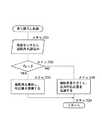
次に、図7に示すカウンタウエイト8の持上げ制御処理では、まず、ステップ11で角度センサ22から回動アーム12の回動角θx を読込む。そして、次なるステップ12では、回動アーム12の回動角θx が図4中に例示する判定角αよりも小さいか否かを判定する。  Next, in the lifting control process of thecounterweight 8 shown in FIG. 7, first, instep 11, the rotation angle θx of therotation arm 12 is read from theangle sensor 22. Then, in thenext step 12, it is determined whether or not the rotation angle θx of therotation arm 12 is smaller than the determination angle α illustrated in FIG.

そして、ステップ12で「YES」と判定する間は、カウンタウエイト昇降機構10により地面から持上げられたカウンタウエイト8が、旋回フレーム4のウエイト取付板4Aから十分に離れた位置にあるので、ステップ13に移って傾転アクチュエータ25に制御信号を出力し、該傾転アクチュエータ25により油圧ポンプ23の容量可変部23Aを予め決められた所定の傾転角(傾転位置)に保持する。  While the determination atstep 12 is “YES”, thecounterweight 8 lifted from the ground by thecounterweight lifting mechanism 10 is at a position sufficiently away from theweight mounting plate 4A of the revolvingframe 4. Then, a control signal is output to thetilt actuator 25, and thedisplacement actuator 25 holds thecapacity variable portion 23A of thehydraulic pump 23 at a predetermined tilt angle (tilt position).

これにより、油圧ポンプ23から吐出される圧油の吐出量(流量)は、カウンタウエイト8をカウンタウエイト昇降機構10で持上げるため、油圧シリンダ16を伸長させるのに適正な吐出量が確保できるように制御される。そして、その後はステップ14に移ってリターンされる。  As a result, the discharge amount (flow rate) of the pressure oil discharged from thehydraulic pump 23 lifts thecounterweight 8 with thecounterweight lifting mechanism 10, so that an appropriate discharge amount can be secured for extending thehydraulic cylinder 16. To be controlled. Then, the process proceeds to step 14 and returns.

次に、ステップ11以降の処理を繰返すうちに、ステップ12で「NO」と判定したときには、回動アーム12の回動角θx が図4中の判定角α以上に大きくなり、カウンタウエイト昇降機構10で持上げられたカウンタウエイト8が、旋回フレーム4のウエイト取付板4Aに近付いていると判断することができる。  Next, when it is determined “NO” instep 12 while the processing fromstep 11 onward is repeated, the rotation angle θx of therotation arm 12 becomes larger than the determination angle α in FIG. It can be determined that thecounterweight 8 lifted at 10 is approaching theweight mounting plate 4 </ b> A of the revolvingframe 4.

そこで、この場合にはステップ15に移って傾転角を小さくするように傾転アクチュエータ25に制御信号を出力し、該傾転アクチュエータ25により油圧ポンプ23の容量可変部23Aを小傾転側に駆動する。これによって、油圧ポンプ23から吐出される圧油の吐出量を低減させ、油圧シリンダ16の伸長速度が十分に遅い速度となるように制御する。  Therefore, in this case, the process proceeds to step 15 to output a control signal to the tiltingactuator 25 so as to reduce the tilting angle, and the tiltingactuator 25 moves thedisplacement variable portion 23A of thehydraulic pump 23 to the small tilting side. To drive. Thus, the discharge amount of the pressure oil discharged from thehydraulic pump 23 is reduced, and the extension speed of thehydraulic cylinder 16 is controlled to be sufficiently slow.

この結果、カウンタウエイト8は、旋回フレーム4のウエイト取付板4Aに近付くに従ってカウンタウエイト昇降機構10による持上げ速度が遅くなるように抑えられ、重量物であるカウンタウエイト8がウエイト取付板4Aに衝突するのを防ぐことができる。そして、その後はステップ14に移ってリターンする。  As a result, thecounterweight 8 is suppressed so that the lifting speed by thecounterweight lifting mechanism 10 becomes slower as it approaches theweight mounting plate 4A of theswivel frame 4, and thecounterweight 8 which is a heavy object collides with theweight mounting plate 4A. Can be prevented. Thereafter, the process proceeds to step 14 and returns.

次に、図8に示すカウンタウエイト8の吊り降ろし制御処理では、まず、ステップ21で角度センサ22から回動アーム12の回動角θx を読込む。そして、次なるステップ22では、回動アーム12の回動角θx が図3中に例示する判定角βよりも大きい否かを判定する。  Next, in the suspension control process of thecounterweight 8 shown in FIG. 8, first, instep 21, the rotation angle θx of therotation arm 12 is read from theangle sensor 22. In thenext step 22, it is determined whether or not the rotation angle θx of therotation arm 12 is larger than the determination angle β illustrated in FIG.

そして、ステップ22で「YES」と判定する間は、旋回フレーム4のウエイト取付板4Aからカウンタウエイト昇降機構10により地面に向け吊り降ろされているカウンタウエイト8が、例えば判定角βに相当する高さ以上に地面から離れているので、ステップ23に移って傾転アクチュエータ25に制御信号を出力し、該傾転アクチュエータ25により油圧ポンプ23の容量可変部23Aを予め決められた所定の傾転角(傾転位置)に保持する。  During the determination of “YES” instep 22, thecounterweight 8 suspended from theweight mounting plate 4 </ b> A of theturning frame 4 toward the ground by thecounterweight lifting mechanism 10 is, for example, a height corresponding to the determination angle β. Since it is further away from the ground, the process proceeds to step 23 to output a control signal to the tiltingactuator 25, and the tiltingactuator 25 causes thedisplacement variable portion 23A of thehydraulic pump 23 to be set at a predetermined tilting angle. Hold at (tilting position).

これにより、油圧ポンプ23から吐出される圧油の吐出量(流量)は、カウンタウエイト8をカウンタウエイト昇降機構10で吊り降ろすため、油圧シリンダ16を縮小させるのに適正な吐出量が確保できるように制御される。そして、その後はステップ24に移ってリターンされる。  As a result, the discharge amount (flow rate) of the pressure oil discharged from thehydraulic pump 23 suspends thecounterweight 8 by thecounterweight lifting mechanism 10, so that an appropriate discharge amount can be secured for reducing thehydraulic cylinder 16. Controlled. Then, the process proceeds to step 24 and returns.

次に、ステップ21以降の処理を繰返すうちに、ステップ22で「NO」と判定したときには、回動アーム12の回動角θx が図3中の判定角β以下となり、カウンタウエイト昇降機構10で吊り降ろされているカウンタウエイト8が、地面に近付いていると判断することができる。  Next, when it is determined “NO” instep 22 while the processing fromstep 21 is repeated, the rotation angle θx of therotation arm 12 becomes equal to or less than the determination angle β in FIG. It can be determined that thecounterweight 8 being suspended is approaching the ground.

そこで、この場合にはステップ25に移って傾転角を小さくするように傾転アクチュエータ25に制御信号を出力し、該傾転アクチュエータ25により油圧ポンプ23の容量可変部23Aを小傾転側に駆動する。これによって、油圧ポンプ23から吐出される圧油の吐出量を低減させ、油圧シリンダ16の縮小速度が十分に遅い速度となるように制御する。  Therefore, in this case, the control signal is outputted to the tiltingactuator 25 so as to decrease the tilting angle inStep 25, and thedisplacement actuator 23A of thehydraulic pump 23 is moved to the small tilting side by the tiltingactuator 25. To drive. Thus, the discharge amount of the pressure oil discharged from thehydraulic pump 23 is reduced, and the reduction speed of thehydraulic cylinder 16 is controlled to be sufficiently slow.

この結果、カウンタウエイト8は、その下面が地面に近付くに従ってカウンタウエイト昇降機構10による吊り降ろし速度が遅くなるように抑えられ、重量物であるカウンタウエイト8が地面に強く衝突するのを防止できると共に、カウンタウエイト8をゆっくりと地面に降ろすことができる。そして、その後はステップ24に移ってリターンする。  As a result, thecounterweight 8 is suppressed so that the suspension speed of thecounterweight lifting mechanism 10 is lowered as the lower surface thereof approaches the ground, and theheavyweight counterweight 8 can be prevented from strongly colliding with the ground. Thecounterweight 8 can be slowly lowered onto the ground. Thereafter, the process proceeds to step 24 and returns.

従って、本実施の形態によれば、カウンタウエイト昇降機構10の油圧シリンダ16(ロッド16C)を伸長または縮小させて、カウンタウエイト8を持上げまたは吊り降ろすように昇降駆動するときに、油圧ポンプ23の吐出量を可変に制御することができ、カウンタウエイト8の昇降速度が過度に速くなるのを抑えることができる。  Therefore, according to the present embodiment, when the hydraulic cylinder 16 (rod 16C) of thecounterweight lifting mechanism 10 is extended or contracted and lifted or lowered to lift or suspend thecounterweight 8, thehydraulic pump 23 The discharge amount can be variably controlled, and it is possible to prevent the lifting / lowering speed of thecounterweight 8 from becoming excessively high.

このため、例えば不慣れなオペレータがカウンタウエイト8の昇降操作を行う場合でも、カウンタウエイト8の昇降位置に応じて油圧シリンダ16の伸縮速度を適正に制御することができ、カウンタウエイト8が旋回フレーム4の後端側に衝突したり、地面側に衝突したりするのを防止できる。そして、旋回フレーム4に対するカウンタウエイト8の取付け、取外し作業を円滑に行うことができる。  Therefore, for example, even when an unfamiliar operator performs the lifting / lowering operation of thecounterweight 8, the expansion / contraction speed of thehydraulic cylinder 16 can be appropriately controlled according to the lifting / lowering position of thecounterweight 8. It is possible to prevent a collision with the rear end side or a collision with the ground side. And the attachment and removal work of thecounterweight 8 with respect to theturning frame 4 can be performed smoothly.

次に、図9ないし図11は本発明の第2の実施の形態を示し、本実施の形態の特徴は、油圧シリンダに給排する圧油の圧力を検出する圧力センサにより、カウンタウエイトの昇降位置を検出する位置検出手段を構成したことにある。なお、本実施の形態では、前述した第1の実施の形態と同一の構成要素に同一の符号を付し、その説明を省略するものとする。  Next, FIGS. 9 to 11 show a second embodiment of the present invention. The feature of this embodiment is that the counterweight is raised and lowered by a pressure sensor that detects the pressure of the pressure oil supplied to and discharged from the hydraulic cylinder. The position detecting means for detecting the position is configured. In the present embodiment, the same components as those in the first embodiment described above are denoted by the same reference numerals, and the description thereof is omitted.

図中、41は位置検出手段を構成する圧力センサで、該圧力センサ41は、例えば図9に示す如く、油圧シリンダ16のボトム側に位置する油室Bとスローリターンバルブ29との間で主管路26Bの途中に配置されている。そして、圧力センサ41は、油圧シリンダ16の油室Bに給排する圧油の圧力Pを、図10に示す特性線42のように検出する。  In the figure,reference numeral 41 denotes a pressure sensor that constitutes a position detecting means. Thepressure sensor 41 is connected between the oil chamber B located on the bottom side of thehydraulic cylinder 16 and theslow return valve 29, for example, as shown in FIG. It is arranged in the middle of thepath 26B. Thepressure sensor 41 detects the pressure P of the pressure oil supplied to and discharged from the oil chamber B of thehydraulic cylinder 16 as indicated by a characteristic line 42 shown in FIG.

即ち、本発明者は、図2〜図4に例示したカウンタウエイト昇降機構10による回動アーム12の回動角θx と油圧シリンダ16(油室B)の圧力Pとの関係を調査し、回動角θx が最小角θ0 から最大角θa まで変化するときに、圧力Pは、図10中の特性線42のように変動することを確認した。  That is, the inventor investigates the relationship between the rotation angle θx of therotation arm 12 by thecounterweight lifting mechanism 10 illustrated in FIGS. 2 to 4 and the pressure P of the hydraulic cylinder 16 (oil chamber B). When the dynamic angle θx changes from the minimum angle θ0 to the maximum angle θa, it was confirmed that the pressure P fluctuated as shown by the characteristic line 42 in FIG.

この場合、カウンタウエイト8を図4に示すように地面から持上げ始めるときに、回動アーム12の回動角θx は最小角θ0 であるが、油圧シリンダ16の圧力Pは、回動アーム12からのモーメント等に影響されて大きな圧力値P0 まで上昇する。そして、カウンタウエイト8を図3に示す上昇位置まで持上げ、回動角θx が最大角θa とるときには、油圧シリンダ16内の圧力Pは、漸次減少して圧力値Pa まで低下するものである。  In this case, when thecounterweight 8 starts to be lifted from the ground as shown in FIG. 4, the rotation angle θx of therotation arm 12 is the minimum angle θ0, but the pressure P of thehydraulic cylinder 16 is changed from therotation arm 12. As a result, the pressure rises to a large pressure value P0. When thecounterweight 8 is lifted to the raised position shown in FIG. 3 and the rotation angle θx reaches the maximum angle θa, the pressure P in thehydraulic cylinder 16 gradually decreases to a pressure value Pa.

43は制御手段としてのコントローラで、該コントローラ43は、第1の実施の形態で述べたコントローラ34とほぼ同様に構成されている。そして、コントローラ43は、その入力側が操作検出器33等に接続され、その出力側は傾転アクチュエータ25等に接続されている。しかし、この場合のコントローラ43は、その入力側に位置検出手段としての圧力センサ41が接続されている。  Reference numeral 43 denotes a controller as control means, and thecontroller 43 is configured in substantially the same manner as thecontroller 34 described in the first embodiment. Thecontroller 43 has an input side connected to theoperation detector 33 and the like, and an output side connected to thetilt actuator 25 and the like. However, thecontroller 43 in this case is connected to apressure sensor 41 as position detecting means on the input side.

また、コントローラ43は、ROM,RAM等からなる記憶部43Aを有し、該記憶部43A内には、前述した図6に示す処理プログラムに加えて、図11に示す持上げ制御処理用のプログラムと、圧力Pの判定値Pb 等とが格納されている。そして、油圧シリンダ16内の圧力Pが判定値Pb まで低下したときには、図10に示す特性線42から回動アーム12の回動角θx が角度θb となり、最大角θa に近付いていることを判定できるものである。  Thecontroller 43 has astorage unit 43A composed of a ROM, a RAM, and the like. In thestorage unit 43A, in addition to the processing program shown in FIG. 6, the lifting control processing program shown in FIG. And a determination value Pb of the pressure P and the like are stored. When the pressure P in thehydraulic cylinder 16 decreases to the determination value Pb, it is determined from the characteristic line 42 shown in FIG. 10 that the rotation angle θx of therotation arm 12 becomes the angle θb and approaches the maximum angle θa. It can be done.

ここで、コントローラ43は、図11の処理プログラムに従ってカウンタウエイト8の持上げ制御処理を行う。まず、ステップ31では圧力センサ41から油圧シリンダ16の圧力Pを読込む。そして、次なるステップ32では、このときの圧力Pが図10中に例示する判定値Pb よりも大きい圧力であるか否かを判定する。  Here, thecontroller 43 performs lifting control processing of thecounterweight 8 according to the processing program of FIG. First, instep 31, the pressure P of thehydraulic cylinder 16 is read from thepressure sensor 41. In thenext step 32, it is determined whether or not the pressure P at this time is larger than the determination value Pb illustrated in FIG.

そして、ステップ32で「YES」と判定する間は、カウンタウエイト昇降機構10により地面から持上げられたカウンタウエイト8が、旋回フレーム4のウエイト取付板4Aから離れた位置にあるので、ステップ33に移って傾転アクチュエータ25に制御信号を出力し、該傾転アクチュエータ25により油圧ポンプ23の容量可変部23Aを予め決められた所定の傾転角(傾転位置)に保持する。  While the determination atstep 32 is “YES”, since thecounterweight 8 lifted from the ground by thecounterweight lifting mechanism 10 is located away from theweight mounting plate 4A of theturning frame 4, the process proceeds to step33. Then, a control signal is output to the tiltingactuator 25, and thedisplacement actuator 25 holds thecapacity variable portion 23A of thehydraulic pump 23 at a predetermined tilting angle (tilting position).

これにより、油圧ポンプ23から吐出される圧油の吐出量(流量)は、カウンタウエイト8をカウンタウエイト昇降機構10で持上げるため、油圧シリンダ16を伸長させるのに適正な吐出量が確保できるように制御される。そして、その後はステップ34に移ってリターンされる。  As a result, the discharge amount (flow rate) of the pressure oil discharged from thehydraulic pump 23 lifts thecounterweight 8 with thecounterweight lifting mechanism 10, so that an appropriate discharge amount can be secured for extending thehydraulic cylinder 16. Controlled. Thereafter, the process proceeds to step 34 and returns.

次に、ステップ31以降の処理を繰返すうちに、ステップ32で「NO」と判定したときには、油圧シリンダ16の圧力Pが図10中の判定値Pb 以下まで下がり、カウンタウエイト昇降機構10で持上げられたカウンタウエイト8が、旋回フレーム4のウエイト取付板4Aに近付いていると判断することができる。  Next, when it is determined as “NO” instep 32 while the processing afterstep 31 is repeated, the pressure P of thehydraulic cylinder 16 is lowered to the determination value Pb or less in FIG. 10 and lifted by thecounterweight lifting mechanism 10. It can be determined that thecounterweight 8 is approaching theweight mounting plate 4 </ b> A of the revolvingframe 4.

そこで、この場合にはステップ35に移って傾転角を小さくするように傾転アクチュエータ25に制御信号を出力し、該傾転アクチュエータ25により油圧ポンプ23の容量可変部23Aを小傾転側に駆動する。これによって、油圧ポンプ23から吐出される圧油の吐出量を低減させ、油圧シリンダ16の伸長速度が十分に遅い速度となるように制御する。  Therefore, in this case, the control signal is output to thetilt actuator 25 so as to decrease the tilt angle in Step 35, and thedisplacement actuator 23A of thehydraulic pump 23 is moved to the small tilt side by thetilt actuator 25. To drive. Thus, the discharge amount of the pressure oil discharged from thehydraulic pump 23 is reduced, and the extension speed of thehydraulic cylinder 16 is controlled to be sufficiently slow.

この結果、カウンタウエイト8は、旋回フレーム4のウエイト取付板4Aに近付くに従ってカウンタウエイト昇降機構10による持上げ速度が遅くなるように抑えられ、重量物であるカウンタウエイト8がウエイト取付板4Aに衝突するのを防ぐことができる。そして、その後はステップ34に移ってリターンする。  As a result, thecounterweight 8 is restrained so that the lifting speed by thecounterweight lifting mechanism 10 becomes slower as it approaches theweight mounting plate 4A of the revolvingframe 4, and thecounterweight 8 that is a heavy object collides with theweight mounting plate 4A. Can be prevented. Then, the process proceeds to step 34 and returns.

かくして、このように構成される本実施の形態でも、コントローラ43は、圧力センサ41からの検出信号に基づき傾転アクチュエータ25を駆動制御することにより、油圧ポンプ23の容量可変部23Aを大傾転位置と小傾転位置との間で適宜に傾転させ、カウンタウエイト昇降機構10によるカウンタウエイト8の持上げ動作時に衝撃等が発生するのを抑えることができる。  Thus, also in the present embodiment configured as described above, thecontroller 43 controls thetilt actuator 25 based on the detection signal from thepressure sensor 41, thereby greatly tilting thedisplacement variable portion 23A of thehydraulic pump 23. By appropriately tilting between the position and the small tilt position, it is possible to suppress the occurrence of an impact or the like when thecounterweight 8 is lifted by thecounterweight lifting mechanism 10.

特に、本実施の形態では、圧力センサ41からの検出信号によりカウンタウエイト8の昇降位置を識別する構成としているので、例えば第1の実施の形態で述べた角度センサ22を不要にすることができ、比較的安価な圧力センサ41を用いて、カウンタウエイト8の位置を検出することができる。  In particular, in the present embodiment, since the lift position of thecounterweight 8 is identified by the detection signal from thepressure sensor 41, for example, theangle sensor 22 described in the first embodiment can be eliminated. The position of thecounterweight 8 can be detected using the relativelyinexpensive pressure sensor 41.

なお、前記第1の実施の形態では、角度センサ22を用いてカウンタウエイト8の昇降位置を検出する場合を例に挙げて説明した。しかし、本発明はこれに限るものではなく、例えば油圧シリンダ16のロッド16C等にストロークセンサ(位置検出手段)を設け、該ストロークセンサからの検出信号によりカウンタウエイト8の昇降位置を検出する構成としてもよい。  In the first embodiment, the case where the lift position of thecounterweight 8 is detected using theangle sensor 22 has been described as an example. However, the present invention is not limited to this. For example, a stroke sensor (position detecting means) is provided on therod 16C of thehydraulic cylinder 16 and the lift position of thecounterweight 8 is detected by a detection signal from the stroke sensor. Also good.

また、前記各実施の形態では、傾転アクチュエータ25をコントローラ34,43からの電気的な制御信号により駆動制御する場合を例に挙げて説明した。しかし、本発明はこれに限るものではなく、例えば電気信号を油圧信号に切換えて傾転アクチュエータを油圧力で作動させる構成としてもよいものである。  Further, in each of the above embodiments, the case where thetilt actuator 25 is driven and controlled by the electric control signals from thecontrollers 34 and 43 has been described as an example. However, the present invention is not limited to this. For example, the tilting actuator may be operated with the hydraulic pressure by switching the electric signal to the hydraulic signal.

一方、前記各実施の形態では、操作検出器33により操作レバー32Aが中立位置にあるか、または図5中の矢示C,D方向のいずれに傾転操作されたかを検出する場合を例に挙げて説明した。しかし、本発明はこれに限るものではなく、例えば方向制御弁27が中立位置(イ)、切換位置(ロ),(ハ)のいずれの位置にあるかを検出する操作検出器で構成してもよいものである。  On the other hand, in each of the above-described embodiments, an example in which theoperation detector 33 detects whether theoperation lever 32A is in the neutral position or is tilted in the directions indicated by arrows C and D in FIG. I gave it as an explanation. However, the present invention is not limited to this. For example, thedirectional control valve 27 is constituted by an operation detector that detects whether thedirectional control valve 27 is in the neutral position (A), the switching position (B), or (C). Is also good.

また、前記各実施の形態では、油圧ショベル1のカウンタウエイト8を旋回フレーム4の後端側から取付け、取外しする場合を例に挙げて説明した。しかし、本発明はこれに限らず、例えば油圧クレーン、ホイールローダ、ブルドーザまたは各種の作業機械等のように、車体の後端側等にカウンタウエイトを着脱可能に搭載する型式の種々の建設機械にも適用できるものである。  In each of the above embodiments, the case where thecounterweight 8 of theexcavator 1 is attached and removed from the rear end side of the revolvingframe 4 has been described as an example. However, the present invention is not limited to this. For example, various construction machines such as a hydraulic crane, a wheel loader, a bulldozer, or various work machines, in which a counterweight is detachably mounted on the rear end side of the vehicle body. Is also applicable.

本発明の第1の実施の形態によるカウンタウエイト昇降機構が適用された油圧ショベルを示す正面図である。1 is a front view showing a hydraulic excavator to which a counterweight lifting mechanism according to a first embodiment of the present invention is applied.カウンタウエイトを省略した状態で旋回フレームのウエイト取付板およびカウンタウエイト昇降機構等を図1中の矢示II−II方向からみた矢示図である。FIG. 2 is an arrow view of a swing frame weight mounting plate, a counter weight lifting mechanism and the like viewed from an arrow II-II direction in FIG. 1 with a counterweight omitted.旋回フレームの後端側にカウンタウエイトを持上げた状態の昇降機構を図2中の矢示 III−III 方向からみた断面図である。It is sectional drawing which looked at the raising / lowering mechanism of the state which lifted the counterweight to the rear end side of the turning frame from the arrow III-III direction in FIG.カウンタウエイト昇降機構によりカウンタウエイトを地面に吊り降ろした状態を示す図3と同様位置での断面図である。It is sectional drawing in the same position as FIG. 3 which shows the state which suspended the counterweight on the ground with the counterweight raising / lowering mechanism.昇降用の油圧シリンダを駆動制御するカウンタウエイト昇降用の油圧回路等を示す制御回路図である。FIG. 2 is a control circuit diagram showing a counterweight lifting hydraulic circuit and the like for driving and controlling a lifting hydraulic cylinder.図5中のコントローラによるカウンタウエイトの昇降制御処理を示す流れ図である。6 is a flowchart showing a counterweight raising / lowering control process by the controller in FIG. 5.図6に続くカウンタウエイトの持上げ制御処理を示す流れ図である。FIG. 7 is a flowchart showing a counterweight lifting control process following FIG. 6. FIG.図6に続くカウンタウエイトの吊り降ろし制御処理を示す流れ図である。FIG. 7 is a flowchart showing a counterweight hanging control process following FIG. 6. FIG.第2の実施の形態によるカウンタウエイト昇降用の油圧回路等を示す制御回路図である。It is a control circuit diagram which shows the hydraulic circuit etc. for counterweight raising / lowering by 2nd Embodiment.回動アームの回動角と油圧シリンダ側の圧力との関係を示す特性線図である。It is a characteristic diagram which shows the relationship between the rotation angle of a rotation arm, and the pressure of the hydraulic cylinder side.図9中のコントローラによるカウンタウエイトの持上げ制御処理を示す流れ図である。10 is a flowchart showing counterweight lifting control processing by the controller in FIG. 9.

符号の説明Explanation of symbols

1 油圧ショベル(建設機械)
2 下部走行体
3 上部旋回体(車体)
4 旋回フレーム
4A ウエイト取付板
5 キャブ
7 作業装置
8 カウンタウエイト
10 カウンタウエイト昇降機構
11 ブラケット
12 回動アーム
13,18,20 連結ピン
14 連結バー
15 吊り金具
16 油圧シリンダ
16A チューブ
16C ロッド
22 角度センサ(位置検出手段)
23 油圧ポンプ(油圧源)
23A 容量可変部
24 タンク
25 傾転アクチュエータ(容量可変アクチュエータ)
27 方向制御弁
29 スローリターンバルブ
32 パイロット操作弁
32A 操作レバー
34,43 コントローラ(制御手段)
41 圧力センサ(位置検出手段)
1 Excavator (construction machine)
2 Lower travelingbody 3 Upper turning body (vehicle body)
DESCRIPTION OFSYMBOLS 4Rotating frame 4A Weight mounting plate 5 Cab 7Working device 8Counter weight 10 Counter weight raising / loweringmechanism 11Bracket 12Rotating arm 13, 18, 20 Connectingpin 14 Connectingbar 15Hanging bracket 16Hydrauliccylinder 16ATube 16C Rod 22 Angle sensor ( Position detection means)
23 Hydraulic pump (hydraulic power source)
23A Capacityvariable part 24Tank 25 Tilt actuator (Capacity variable actuator)
27Directional control valve 29Slow return valve 32 Pilot operatedvalve32A Operating lever 34, 43 Controller (control means)
41 Pressure sensor (position detection means)

Claims (4)

Translated fromJapanese
作業装置が設けられた車体と、前記作業装置に対する該車体の重量バランスをとるため該車体のフレームに着脱可能に設けられるカウンタウエイトと、前記フレームに設けられ該カウンタウエイトをフレームに対して取付け、取外しするときに、油圧シリンダを用いて該カウンタウエイトを上,下に昇降させるカウンタウエイト昇降機構と、該カウンタウエイト昇降機構の油圧シリンダに圧油を供給する油圧源とを備えてなる建設機械において、
前記油圧源は、可変容量型の油圧ポンプにより構成し、
該可変容量型の油圧ポンプは、前記油圧シリンダによってカウンタウエイトを昇降駆動するときに、該カウンタウエイトの昇降位置に従って圧油の吐出量を可変に制御する構成としたことを特徴とする建設機械。
A vehicle body provided with a working device, a counterweight detachably provided on the frame of the vehicle body to balance the weight of the vehicle body with respect to the working device, and the counterweight provided on the frame attached to the frame; In a construction machine comprising a counterweight lifting mechanism that lifts and lowers the counterweight using a hydraulic cylinder when removing, and a hydraulic source that supplies pressure oil to the hydraulic cylinder of the counterweight lifting mechanism ,
The hydraulic source is composed of a variable displacement hydraulic pump,
The construction machine characterized in that the variable displacement hydraulic pump is configured to variably control the discharge amount of the pressure oil according to the lift position of the counterweight when the counterweight is driven up and down by the hydraulic cylinder.
前記カウンタウエイトの昇降位置を検出する位置検出手段と、該位置検出手段からの検出信号に従って前記油圧ポンプの容量可変アクチュエータを駆動制御する制御手段とを備えてなる請求項1に記載の建設機械。  2. The construction machine according to claim 1, further comprising position detecting means for detecting the raising / lowering position of the counterweight, and control means for driving and controlling the displacement variable actuator of the hydraulic pump according to a detection signal from the position detecting means. 前記カウンタウエイト昇降機構は、前記車体のフレームに固定して設けられたブラケットと、基端側が該ブラケットに回動可能に取付けられ先端側が前記カウンタウエイトに連結される回動アームと、前記油圧ポンプからの圧油で伸縮されることにより該回動アームを上,下方向に回動して前記カウンタウエイトを昇降させる前記油圧シリンダとを含んで構成し、前記回動アームまたは油圧シリンダの回動部位には、前記カウンタウエイトの昇降位置を検出する位置検出手段を設ける構成としてなる請求項1または2に記載の建設機械。  The counterweight raising / lowering mechanism includes a bracket fixed to the frame of the vehicle body, a pivot arm having a proximal end rotatably attached to the bracket and a distal end connected to the counterweight, and the hydraulic pump. And the hydraulic cylinder that lifts and lowers the counterweight by rotating the rotary arm upward and downward by being expanded and contracted by pressure oil from the rotary arm. The construction machine according to claim 1 or 2, wherein the part is provided with a position detecting means for detecting a lifted position of the counterweight. 前記位置検出手段は、前記油圧ポンプから油圧シリンダに供給する圧油の圧力を検出する圧力センサにより構成してなる請求項2に記載の建設機械。  The construction machine according to claim 2, wherein the position detection unit is configured by a pressure sensor that detects a pressure of pressure oil supplied from the hydraulic pump to a hydraulic cylinder.
JP2007097429A2007-04-032007-04-03 Construction machineryPendingJP2008255611A (en)

Priority Applications (1)

Application NumberPriority DateFiling DateTitle
JP2007097429AJP2008255611A (en)2007-04-032007-04-03 Construction machinery

Applications Claiming Priority (1)

Application NumberPriority DateFiling DateTitle
JP2007097429AJP2008255611A (en)2007-04-032007-04-03 Construction machinery

Publications (1)

Publication NumberPublication Date
JP2008255611Atrue JP2008255611A (en)2008-10-23

Family

ID=39979466

Family Applications (1)

Application NumberTitlePriority DateFiling Date
JP2007097429APendingJP2008255611A (en)2007-04-032007-04-03 Construction machinery

Country Status (1)

CountryLink
JP (1)JP2008255611A (en)

Cited By (3)

* Cited by examiner, † Cited by third party
Publication numberPriority datePublication dateAssigneeTitle
JP2011236592A (en)*2010-05-072011-11-24Hitachi Constr Mach Co LtdHydraulic circuit for attaching and detaching counterweight of work machine
JP2015178732A (en)*2014-03-192015-10-08日本車輌製造株式会社Construction machine
WO2016139226A1 (en)*2015-03-022016-09-09Caterpillar SarlMoving device for counterweight

Cited By (6)

* Cited by examiner, † Cited by third party
Publication numberPriority datePublication dateAssigneeTitle
JP2011236592A (en)*2010-05-072011-11-24Hitachi Constr Mach Co LtdHydraulic circuit for attaching and detaching counterweight of work machine
JP2015178732A (en)*2014-03-192015-10-08日本車輌製造株式会社Construction machine
WO2016139226A1 (en)*2015-03-022016-09-09Caterpillar SarlMoving device for counterweight
CN107257772A (en)*2015-03-022017-10-17卡特彼勒Sarl mobile device for counterweight
US10407283B2 (en)2015-03-022019-09-10Caterpillar SarlMoving device for counterweight
CN107257772B (en)*2015-03-022019-12-27卡特彼勒SarlMoving device for counterweight

Similar Documents

PublicationPublication DateTitle
JP5969379B2 (en) Excavator and excavator control method
JP5410373B2 (en) Double-armed work machine
WO2011046184A1 (en)Hydraulic system for operating machine
CN104619999B (en) construction machinery
WO2011105027A1 (en)Hydraulic pressure control device
JP6625575B2 (en) Construction machinery
WO2021085477A1 (en)Construction machine
JP6605316B2 (en) Drive device for work machine
WO2017061220A1 (en)Construction machinery
JP2008255611A (en) Construction machinery
JP2011038298A (en)Hydraulic controller of construction machine
JP6585012B2 (en) Excavator
JP6781181B2 (en) Work machine with telescopic arm
JP6953216B2 (en) Excavator
JP2021088896A (en)Hydraulic circuit of construction machine
JP2001199676A (en)Hydraulic circuit for operation system of construction machine
JP6585013B2 (en) Excavator
JP2010242306A (en)Hydraulic control device for construction machinery
JPH08302754A (en) Boom speed controller for work equipment
JP2015059301A (en)Gravity center variable device
JP3634601B2 (en) Hydraulic pump control device for swivel construction machine
JP2013113035A (en)Impact prevention control method and impact prevention control device for bucket cylinder of loading shovel
JP5320003B2 (en) Hydraulic control device for work machine
JP5328279B2 (en) Float control system for work equipment
CN113874584A (en)Working machine

[8]ページ先頭

©2009-2025 Movatter.jp