JP2008249431A - 3D image correction method and apparatus - Google Patents
3D image correction method and apparatusDownload PDFInfo
- Publication number
- JP2008249431A JP2008249431AJP2007089759AJP2007089759AJP2008249431AJP 2008249431 AJP2008249431 AJP 2008249431AJP 2007089759 AJP2007089759 AJP 2007089759AJP 2007089759 AJP2007089759 AJP 2007089759AJP 2008249431 AJP2008249431 AJP 2008249431A
- Authority
- JP
- Japan
- Prior art keywords
- image
- dimensional
- distance
- camera
- subject
- Prior art date
- Legal status (The legal status is an assumption and is not a legal conclusion. Google has not performed a legal analysis and makes no representation as to the accuracy of the status listed.)
- Granted
Links
Images


Landscapes
- Length Measuring Devices By Optical Means (AREA)
- Measurement Of Optical Distance (AREA)
- Optical Radar Systems And Details Thereof (AREA)
Abstract
Translated fromJapaneseDescription
Translated fromJapanese本発明は、3次元画像補正方法及びその装置に関し、3次元カメラで被写体の輝度画像と距離画像を補正して被写体の3次元座標を演算する3次元画像補正方法及びその装置に関する。 The present invention relates to a three-dimensional image correction method and apparatus, and to a three-dimensional image correction method and apparatus for correcting a luminance image and a distance image of a subject with a three-dimensional camera and calculating three-dimensional coordinates of the subject.
2次元画像センサを用いた高速な3次元情報検出装置は、多くの産業分野で応用が期待されている。例えば、放送や映画、デジタルシネマにおいては、得られた3次元情報を用いた映像表現や3次元コンピュータグラフィックス、ゲーム制作など、新たな映像コンテンツ制作への応用が可能である。 A high-speed three-dimensional information detection apparatus using a two-dimensional image sensor is expected to be applied in many industrial fields. For example, in broadcasting, movies, and digital cinema, application to new video content production such as video expression using the obtained 3D information, 3D computer graphics, and game production is possible.
また、センシング用途としては、カメラから被写体までの距離や形状、障害物の有無を画像として検知できるため、セキュリティや交通監視、ナビゲーション、ロポットビジョン、災害時の救助探索などへの利用が考えられる。 As sensing applications, since the distance and shape from the camera to the subject and the presence or absence of obstacles can be detected as images, it can be used for security, traffic monitoring, navigation, robot vision, and rescue search in the event of a disaster.
更に、3次元情報の精度向上により、医療の診断や治療、CAD、部品検査、3次元モデリング、人体計測など、応用分野は広く、社会に大きく貢献できると期待される。 Furthermore, by improving the accuracy of three-dimensional information, it is expected that it can contribute greatly to society in a wide range of application fields such as medical diagnosis and treatment, CAD, parts inspection, three-dimensional modeling, and human body measurement.
従来の3次元情報検出方法を大別すると、複数の撮影画像より距離を求める受動型方式と、空問的もしくは時間的に変調された光を被写体に照射して距雌を検出する能動型方式がある。 The conventional three-dimensional information detection method can be roughly divided into a passive method for obtaining a distance from a plurality of captured images, and an active method for detecting a distance female by irradiating a subject with a spatially or temporally modulated light. There is.
受動型方式にはマルチカメラステレオ法やレンズ焦点法があるこの方法は、光照射が不用で、屋外でも使用できるメリットがある一方、3次元情報を求めるには煩雑で時間を要する画像処理が必要である。 There are multi-camera stereo methods and lens focus methods for passive methods. This method does not require light irradiation and has the advantage that it can be used outdoors, but it requires complicated and time-consuming image processing to obtain 3D information. It is.
近年の高速演算プロセッサやソフトウェアの進歩や、安価で高性能なカメラの普及により、距離検出速度と精度が向上し、画素数256(H)×240(V)、フレームレート30Hz、7ビット精度の距離画像検出が報告されている(例えば非特許文献1参照。)。 With recent advances in high-speed arithmetic processors and software, and the spread of inexpensive and high-performance cameras, distance detection speed and accuracy have improved, with a pixel count of 256 (H) × 240 (V), a frame rate of 30 Hz, and a 7-bit accuracy. Distance image detection has been reported (for example, see Non-Patent Document 1).
一方、能動型方式のものでは、光照射が必要であるため外乱光や被写体表面の反射特性の影響を受けやすいものの、光飛行時間計測法など、シンプルな構成で高精度な距離検出ができる。 On the other hand, the active type requires light irradiation and is easily affected by disturbance light and the reflection characteristics of the subject surface, but can detect a distance with high accuracy with a simple configuration such as an optical time-of-flight measurement method.
しかしながら、被写体の3次元情報を得るには、レーザービームを2次元スキャンする必要がある。そのため、リアルタイム検出は難しく、動く被写体の3次元形状を検出するのは困難である。 However, in order to obtain three-dimensional information of the subject, it is necessary to scan the laser beam two-dimensionally. Therefore, real-time detection is difficult, and it is difficult to detect the three-dimensional shape of a moving subject.
また、近年、実時間で距離画像を検出できるカメラが開発されている(例えば特許文献1参照)。
しかし、それらより、被写体の正確な3次元情報を求めるには、カメラレンズのフォーカスデータやズ一ムデータを基に幾何学歪みを補正しなければならない。特にズームレンズの場合、ズーム量やフォーカス量を変化すると、それに応じて歪み特性が大きく変化し、主光線の入射角などが変化し、幾何学歪みを補正するのは困難であるという問題があった。 However, in order to obtain accurate three-dimensional information of the subject, it is necessary to correct geometric distortion based on the focus data and zoom data of the camera lens. Particularly in the case of a zoom lens, if the zoom amount or the focus amount is changed, the distortion characteristics change correspondingly, the incident angle of the chief ray changes, and it is difficult to correct geometric distortion. It was.
本発明は、上記の点に鑑みなされたもので、幾何学歪みを補正して高精度な3次元情報を検出する3次元画像補正方法及びその装置を提供することを目的とする。 The present invention has been made in view of the above points, and an object thereof is to provide a three-dimensional image correction method and apparatus for correcting highly accurate three-dimensional information by correcting geometric distortion.
本発明の一実施態様による3次元画像補正方法は、3次元カメラで被写体の輝度画像と距離画像を撮影し、
前記3次元カメラのレンズデータに応じた歪曲係数を用いて前記輝度画像と前記距離画像を補正し、
補正された輝度画像と距離画像、及び前記3次元カメラのレンズデータに応じた主光線入射角を用いて被写体の3次元座標を演算することにより、幾何学歪みを補正して高精度な3次元情報を検出することができる。A three-dimensional image correction method according to an embodiment of the present invention takes a luminance image and a distance image of a subject with a three-dimensional camera,
Correcting the luminance image and the distance image using a distortion coefficient according to lens data of the three-dimensional camera;
By correcting the geometric distortion by calculating the three-dimensional coordinates of the subject using the corrected luminance image, the distance image, and the chief ray incident angle corresponding to the lens data of the three-dimensional camera, high-precision three-dimensional Information can be detected.
また、本発明の他の実施態様による3次元画像補正方法は、3次元カメラで被写体の輝度画像と距離画像を撮影し、
前記3次元カメラのカメラレンズのズーム値とフォーカス値に応じて予め計測された歪曲係数と主光線入射角と前側主点距離を格納したテーブルから撮影時のズーム値とフォーカス値に応じて歪曲係数と主光線入射角と前側主点距離を検索し、
前記歪曲係数を用いて前記輝度画像と前記距離画像を補正し、
補正された輝度画像と距離画像、及び前記テーブルから検索した主光線入射角と前側主点距離を用いて被写体の3次元座標を演算することにより、幾何学歪みを補正して高精度な3次元情報を検出することができる。In addition, a 3D image correction method according to another embodiment of the present invention takes a luminance image and a distance image of a subject with a 3D camera,
A distortion coefficient according to a zoom value and a focus value at the time of photographing from a table storing a distortion coefficient, a chief ray incident angle and a front principal point distance measured in advance according to a zoom value and a focus value of a camera lens of the three-dimensional camera And the principal ray incident angle and the front principal point distance,
Correcting the luminance image and the distance image using the distortion coefficient;
By correcting the geometric distortion by calculating the three-dimensional coordinates of the subject using the corrected luminance image, the distance image, and the principal ray incident angle and the front principal point distance retrieved from the table, a highly accurate three-dimensional Information can be detected.
本発明の一実施態様による3次元画像補正装置は、被写体の輝度画像と距離画像を撮影する3次元カメラと、
前記3次元カメラのカメラレンズのズーム値とフォーカス値を測定するカメラレンズ測定手段と、
前記3次元カメラのカメラレンズのズーム値とフォーカス値に応じて予め計測された歪曲係数と主光線入射角と前側主点距離を格納したテーブルと、
前記カメラレンズ測定手段で測定された撮影時のズーム値とフォーカス値に応じて前記テーブルから歪曲係数と主光線入射角と前側主点距離を得るテーブル検索手段と、
前記歪曲係数を用いて前記輝度画像と前記距離画像を補正する補正手段と、
前記補正手段で補正された輝度画像と距離画像、及び前記テーブル検索手段で得た主光線入射角と前側主点距離を用いて被写体の3次元座標を演算する3次元座標演算手段とを有することにより、幾何学歪みを補正して高精度な3次元情報を検出することができる。A three-dimensional image correction apparatus according to an embodiment of the present invention includes a three-dimensional camera that captures a luminance image and a distance image of a subject,
Camera lens measuring means for measuring a zoom value and a focus value of a camera lens of the three-dimensional camera;
A table storing a distortion coefficient, a chief ray incident angle, and a front principal point distance measured in advance according to a zoom value and a focus value of a camera lens of the three-dimensional camera;
Table search means for obtaining a distortion coefficient, chief ray incident angle, and front principal point distance from the table according to the zoom value and focus value at the time of photographing measured by the camera lens measurement means,
Correction means for correcting the luminance image and the distance image using the distortion coefficient;
A luminance image and a distance image corrected by the correction means, and a three-dimensional coordinate calculation means for calculating the three-dimensional coordinates of the subject using the principal ray incident angle and the front principal point distance obtained by the table search means. Thus, the geometric distortion can be corrected and highly accurate three-dimensional information can be detected.
前記3次元画像補正装置において、
前記3次元カメラは、被写体の輝度画像と距離画像を同じ画角で撮影する構成とすることができる。In the three-dimensional image correction apparatus,
The three-dimensional camera can be configured to take a luminance image of a subject and a distance image at the same angle of view.
前記3次元画像補正装置において、
前記テーブルは、3次元カメラのカメラレンズのズーム値とフォーカス値に応じて予め計測された複数の像高についての歪曲係数と主光線入射角を格納しており、
前記テーブル検索手段は、前記カメラレンズ測定手段で測定されたズーム値とフォーカス値に応じて前記テーブルから複数の像高についての歪曲係数と主光線入射角を得、
前記補正手段は、前記複数の歪曲係数のうち被写体の像高に対応する歪曲係数で前記輝度画像と前記距離画像を補正し、
前記3次元座標演算手段は、前記複数の歪曲係数のうち被写体の像高に対応する主光線入射角を用いて被写体の3次元座標を演算することができる。In the three-dimensional image correction apparatus,
The table stores distortion coefficients and chief ray incident angles for a plurality of image heights measured in advance according to a zoom value and a focus value of a camera lens of a three-dimensional camera,
The table search means obtains distortion coefficients and principal ray incident angles for a plurality of image heights from the table according to the zoom value and the focus value measured by the camera lens measurement means,
The correction means corrects the luminance image and the distance image with a distortion coefficient corresponding to the image height of a subject among the plurality of distortion coefficients,
The three-dimensional coordinate calculation means can calculate the three-dimensional coordinates of the subject using a chief ray incident angle corresponding to the image height of the subject among the plurality of distortion coefficients.
本発明によれば、幾何学歪みを補正して高精度な3次元情報を検出することができる。 According to the present invention, geometric distortion can be corrected and highly accurate three-dimensional information can be detected.
以下、図面を参照して本発明の実施形態について説明する。 Hereinafter, embodiments of the present invention will be described with reference to the drawings.
図1は、本発明方法を適用した装置の概要を説明するためのブロック図を示す。同図中、3次元カメラ12は被写体の輝度画像と距離画像を取得する。ここでいう輝度画像は、通常のビデオ映像であるカラー画像や、単に画像の輝度だけを表現した濃淡画像(モノクロ画像)を示しており、輝度画像の撮影フレームレートは、一般的なビデオと同等の30Hz〜60Hz程度である。 FIG. 1 is a block diagram for explaining an outline of an apparatus to which the method of the present invention is applied. In the figure, the three-
一方、距離画像とは、カメラの撮像面から被写体までの距離の値を画像の濃淡や、カラー表示などで表現したものである。距離画像の取得には多くの手法があるが、ここで示す3次元カメラ12のように、1つのカメラレンズ13で輝度画像と距離画像の両方を取得するには、光飛行時間計測法を使用した方法が望ましい。 On the other hand, the distance image is an expression of the value of the distance from the imaging surface of the camera to the subject by the shading or color display of the image. There are many methods for acquiring the distance image, but the optical time-of-flight measurement method is used to acquire both the luminance image and the distance image with one
また、様々な大きさや距離にある被写体を撮影して3次元情報を検出する場合は、カメラレンズ13としてズームレンズを用いる。特に、広画角で空間解像度の高い距離情報を実現するには、ハイビジョンテレビ用ズームレンズが適している。このズームレンズとしては、予め焦点距離つまりフォーカスデータと、物体距離(光軸上での対物レンズと物体との距離)つまりズームデータ等のレンズデータをパラメータとし、画像の歪量Dの値を予め測定しておく。 In addition, a zoom lens is used as the
D=(ho−h’)/ho …(1)
ただし、hoは像高、h’は歪み後の像高である。D = (ho−h ′) / ho (1)
However, ho is the image height, and h ′ is the image height after distortion.
カメラレンズ13には、エンコーダ15が取り付けられており、エンコーダ15は、ズームリング及びフォーカスリングの回転に応じて、常時、焦点距離と物体距離の値が出力する。これにより、レンズデータ(焦点距離と物体距離)を常に3次元情報演算部16での演算に反映させることが可能となる。 An
3次元カメラ12は、上記カメラレンズ13が使用でき、輝度画像と距離画像において同じサイズの画像を得ることができる。特にカメラレンズ13のフォーカスやズームを可変した場合においても、同じサイズの輝度画像と距離画像が得られる。 The three-
3次元カメラ12のセンサ部の画素数としては、横方向の分解能を得るには高精細な必要があり、例えばVGAからハイビジョン映像クラス以上の画素数が望ましい。3次元カメラ12の性能としては、輝度画像と距離画像をビデオフレームレート(1/30秒もしくは1/60秒以上)で出カする。実時間処理の場合は、専用のDSP(Digital Signal Processor)もしくはFPGA(Field Programmable Gate Array)を用いてリアルタイムに3次元情報を算出する。 The number of pixels in the sensor unit of the three-
もしくは、撮影した画像を一度メモリやハードディスクに蓄積し、撮影後のオフライン処理によりメモリやハードディスクから画像を読み出して、ソフトウェア演算処理で時間をかけて処理してもよい。 Alternatively, the captured image may be once stored in a memory or a hard disk, and the image may be read out from the memory or the hard disk by offline processing after shooting and processed over time by software calculation processing.
撮影中にズームやフォーカスを変化させる場合、画像データと共にレンズデータを随時保存し、3次元情報演算部16の演算に利用する。動く被写体を計測する場合は、少なくとも1/30秒以下の間隔で、輝度画像と距離画像とレンズデータを取得する。 When the zoom or focus is changed during shooting, the lens data is saved together with the image data as needed and used for the calculation of the three-dimensional
<中心射影モデル>
図2に、中心投影モデルを示す。同図中、結像面20が3次元カメラ12の撮像素子面に相当する。この結像面20上の画像座標P(x,y)に対し、焦点距離flのカメラレンズ23を透過した反対側に仮想画像平面24を想定する。この仮想画像平面24は、カメラレンズ23の前側主点25から焦点距離flの位置に想定する。<Center projection model>
FIG. 2 shows a central projection model. In the figure, the imaging plane 20 corresponds to the imaging element surface of the three-
画像座標P{x,y)21と前側主点25を通る直線が仮想画像平面24と交わる点が仮想画像座標P(x,y)である。なお、この直線が光軸となす角度(主光線入射角)がθである。更に、距離画像で得られる奥行き距離(結像面からカメラ座標までの距離)を考慮することで、3次元物体のカメラ座標P(X,Y,Z)が求められる。 A point where a straight line passing through the image coordinate P {x, y) 21 and the front principal point 25 intersects the virtual image plane 24 is a virtual image coordinate P (x, y). The angle (chief ray incident angle) formed by this straight line with the optical axis is θ. Further, the camera coordinates P (X, Y, Z) of the three-dimensional object can be obtained by considering the depth distance (distance from the imaging plane to the camera coordinates) obtained from the distance image.
<ズームレンズを用いた結像モデル>
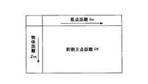
図3に、ズームレンズ32を用いた結像モデルを示す。同図中、結像面30が3次元カメラ12の撮像素子面に相当する。画像座標P(x,y)31は撮像素子面30上の点であり、ズームレンズ32の場合、結像面30と後側主点33間の距離が焦点距離fmである。また、ズームレンズ32の前玉頂点35から前側主点36までの距離(前側主点距離)がPfであり、カメラ座標P(X,Y,Z)と前側主点36を結ぶ直線と光軸のなす角度(主光線入射角)がθである。<Image model using zoom lens>
FIG. 3 shows an imaging model using the zoom lens 32. In the figure, the imaging plane 30 corresponds to the image sensor surface of the three-
ズームレンズ32の場合に輝度画像と距離画像を補正するのに必要なテーブルは、図4に示す歪み後の像高h’の離散的な値をパラメータとしてそれぞれ設けられ焦点距離fmと物体距離Zmをパラメータとして主光線入射角tanθを得る主光線入射角テーブルと、図5に示す焦点距離fmと物体距離Zmをパラメータとして前側主点距離Pfを得る前側主点距離テープルと、図6に示す物体距離Zmの離散的な値をパラメータとしてそれぞれ設けられ焦点距離fmと歪み後の像高h’をパラメータとして歪曲係数Dを得る歪曲係数テープルである。 In the case of the zoom lens 32, the tables necessary for correcting the luminance image and the distance image are respectively provided with discrete values of the image height h ′ after distortion shown in FIG. 4 as parameters, and the focal distance fm and the object distance Zm. A principal ray incident angle table for obtaining a principal ray incident angle tan θ using as a parameter, a front principal point distance table for obtaining a front principal point distance Pf using the focal length fm and the object distance Zm shown in FIG. 5 as parameters, and the object shown in FIG. This is a distortion coefficient table provided with discrete values of the distance Zm as parameters, and obtaining the distortion coefficient D with the focal length fm and the image height h ′ after distortion as parameters.
図7に、本発明方法を適用した装置の一実施形態のブロック図を示す。同図中、3次元カメラ70は、撮影用のズームレンズ71と、輝度画像データを取得する輝度画像撮影部73と、距離画像データを撮影する距離画像撮影部75から構成されている。 FIG. 7 shows a block diagram of an embodiment of an apparatus to which the method of the present invention is applied. In the figure, the three-dimensional camera 70 includes a zoom lens 71 for photographing, a luminance
ここで、距離画像の取得方法の一例について説明する。距離dに置かれた被写体に、図8(A)に示すように、時間と共に係数sで光強度が増加する強度変調光A1を照射し、被写体からの反射光A2を時刻tsにパルス状撮像ゲインA3で短時間撮像した場合、カメラで検出される信号量E+(d,ts)は、(2)式で表される。 Here, an example of a distance image acquisition method will be described. As shown in FIG. 8A, the subject placed at the distance d is irradiated with intensity-modulated light A1 whose light intensity increases with a factor s over time, and the reflected light A2 from the subject is pulsed at time ts. When the image is captured for a short time with the gain A3, the signal amount E + (d, ts) detected by the camera is expressed by equation (2).

ここで、TLはカメラレンズなどのレンズ光学系の透過率、ρは被写体の表面の反射特性係数、F0は光の最大照射強度、Δtは撮像時間幅であり、光変調周期に対して十分小さい値である。また、cは光速、2d/cはカメラから被写体までの距離dを光が往復する時間、lはカメラレンズから被写体までの距離であり、式の分母は光の拡散による減衰を考慮した項である。
Here,TL is the transmittance of a lens optical system such as a camera lens, ρ is the reflection characteristic coefficient of the surface of the object, F0 is the maximum irradiation intensity of light, and Δt is the imaging time width. It is a sufficiently small value. Also, c is the speed of light, 2d / c is the time for the light to travel back and forth between the distance d from the camera to the subject, l is the distance from the camera lens to the subject, and the denominator is a term that takes into account attenuation due to light diffusion. is there.
次に、図8(B)に示すように、時間と共に係数sで光強度が減少する強度変調光A4を照射し、被写体からの反射光A5を時刻tsにパルス状撮像ゲインA3で短時間撮像した場合、カメラで検出される信号量E−(d,ts)は、(3)式で表される。 Next, as shown in FIG. 8B, the intensity-modulated light A4 whose light intensity decreases with a coefficient s with time is irradiated, and the reflected light A5 from the subject is imaged for a short time at the time ts with the pulsed imaging gain A3. In this case, the signal amount E- (d, ts) detected by the camera is expressed by equation (3).
(2)式と(3)式より、光強度の異なる2枚の画像間での強度比R=E+/E−をとり、距離dを求めると、(4)式となる。 When the intensity ratio R = E + / E− between two images having different light intensities is obtained from the expressions (2) and (3) and the distance d is obtained, the expression (4) is obtained.
輝度画像データ及び距離画像データは、放迭規格の映像信号か、もしくは、Camera LinkやLVDS(Low Voltage Differential Signaling)など、高精細画像の高速転送が可能なデジタル信号規格を使用して3次元情報演算部77に供給される。 Luminance image data and distance image data are 3D information using a radio standard video signal or a digital signal standard capable of high-speed transfer of high-definition images, such as Camera Link and LVDS (Low Voltage Differential Signaling). It is supplied to the
3次元カメラ70から出力されたこれらの信号は、DSPやFPGAを用いた専用のハードウエアで構成された3次元情報演算部77で実時間処理される。もしくは、パソコンのメモリやハードディスクに入力して蓄積され、オフラインで読出されて画像処理される。 These signals output from the three-dimensional camera 70 are processed in real time by a three-dimensional
ズームレンズ71にはエンコーダ76が取り付けられており、エンコーダ76は、ズーム値としての物体距離データZmと、フォーカス値としての焦点距離データfmとのレンズデータを測定して、電気信号として3次元情報演算部77に供給する。このレンズデータは、電圧計でモニタし演算に反映させるか、もしくはA/D変換器などのインタフェースを介してデータを取込み、3次元情報演算部77の演算に反映させることができる。このエンコーダ76の出力誤差は、形状算出の誤差となるため、高精度なデータ検出を行う。 An
ズームレンズ71に関しては、予めレンズ特性や歪み特性が実測されている。その測定値から主光線入射角テーブル79と前側主点距離テーブル80、歪曲係数テーブル81が作成されている。これらのテーブル79,80,81から物体距離データZmと焦点距離データfmに基づいて読み出した歪み後の像高h’をパラメータとする複数の主光線入射角tanθ,前側主点距離Pf,歪み後の像高h’をパラメータとする複数の歪曲係数Dの各データを、物体距離データZmと焦点距離データfmに応じて補間部83,84,85にて補間を行い、複数の主光線入射角tanθ、前側主点距離Pf、複数の歪曲係数Dを求める。 Regarding the zoom lens 71, lens characteristics and distortion characteristics are actually measured in advance. A chief ray incident angle table 79, a front principal point distance table 80, and a distortion coefficient table 81 are created from the measured values. A plurality of principal ray incident angles tan θ, front principal point distances Pf, and post-distortion using the image height h ′ after distortion read out from these tables 79, 80, and 81 based on the object distance data Zm and the focal distance data fm. Are interpolated by the
<中心射影モデルでの補正>
輝度画像撮影部73の出力する輝度画像データは、まず、図2に示す中心射影モデルを用いて、画像座標計算部86で画像座標計算を行う。その後、2次元歪み補正部87において、補間部85の出力する歪曲係数Dを用いて2次元画像の歪み補正を行い、仮想画像平面(空間)上の被写体の2次元座標(x,y)を求める。<Correction with central projection model>
The luminance image data output from the luminance
距離画像撮影部75の出力する距離画像データについては、非線形歪み補正部89にて距離検出時に生じる被写体距離と検出値間の非線形歪みを補正する。ここで、横軸に被写体距離、縦軸に距離画像の検出値を取ったグラフは、直線ではなく曲線となる。この曲線は、距離画像を撮影するカメラの特性や撮影時の駆動条件で異なる。非線形歪み補正部89では、この曲線を直線に変換する補正を行っている。 For the distance image data output from the distance
更に、2次元歪み補正部90において、補間部85の出力する歪曲係数Dを用いて2次元歪み補正を行って撮像素子上の結像面から被写体までの距離Rを求める。 Further, the two-dimensional distortion correction unit 90 performs two-dimensional distortion correction using the distortion coefficient D output from the
以上の処理から得られた2次元座標(x,y)、距離R、主光線入射角tanθ、前側主点距離Pfを3次元座標演算部92に供給してカメラ座標P(X,Y,Z)を算出する。 The two-dimensional coordinates (x, y), the distance R, the principal ray incident angle tan θ, and the front principal point distance Pf obtained from the above processing are supplied to the three-dimensional coordinate calculation unit 92 to supply the camera coordinates P (X, Y, Z ) Is calculated.
<ズームレンズを用いた結像モデルでの補正>
次に、ズームレンズの歪曲収差を補正する方法を説明する。はじめに、撮像素子から出力される画像座標x’=kxu,y’=kyvを計算する。ここで、uは撮像画像上のx座標(単位は画素ピッチ)、vは撮像画像上のy座標(単位は画素ピッチ)である。次に、(5)式から歪み後の像高h’を計算する。<Correction with imaging model using zoom lens>
Next, a method for correcting the distortion aberration of the zoom lens will be described. First, image coordinates x ′ = kx u, y ′ = ky v output from the image sensor are calculated. Here, u is the x coordinate (unit is pixel pitch) on the captured image, and v is the y coordinate (unit is pixel pitch) on the captured image. Next, the image height h ′ after distortion is calculated from the equation (5).
h’=(x’2+y’2)1/2 …(5)
焦点距離fm,物体距離Zm,歪み後の像高h’を用いてテーブル81から歪曲係数Dを求める。これより、(6),(7)式で補正した画像座標x,yを計算する。h ′ = (x ′2 + y ′2 )1/2 (5)
A distortion coefficient D is obtained from the table 81 using the focal length fm, the object distance Zm, and the image height h ′ after distortion. From this, the image coordinates x and y corrected by the equations (6) and (7) are calculated.
h=h’/(1+D) …(6)
x=x’/(1+D) …(7)
y=y’/(1+D) …(8)
|ΔD|=|Δh(1+D)2/h’| …(9)
なお、Δhは像高の変化分であり、ΔDは歪曲係数の変化分であるが、Δhを像高の精度、ΔDを歪曲係数の精度と見ることができる。つまり、どの程度の精度でΔDの値が検出できれば、何画素程度の精度で補正できるかの目安を得ている。例えば、1画面の画素数を横1936×縦1086とすると、Dの精度ΔDが小数点以下3桁程度まで有効であれば、歪曲収差の補正精度Δx,Δy,Δhをおおよそ1画素以内に収められることが(8)式から見積もることができる。h = h ′ / (1 + D) (6)
x = x ′ / (1 + D) (7)
y = y ′ / (1 + D) (8)
| ΔD | = | Δh (1 + D)2 / h ′ | (9)
Note that Δh is a change in the image height and ΔD is a change in the distortion coefficient. However, Δh can be regarded as the accuracy of the image height and ΔD can be regarded as the accuracy of the distortion coefficient. In other words, a standard of how much accuracy can be corrected if the value of ΔD can be detected with high accuracy is obtained. For example, if the number of pixels on one screen is 1936 × 1086, and if the D accuracy ΔD is effective up to about 3 digits after the decimal point, the distortion correction accuracy Δx, Δy, Δh can be within one pixel. Can be estimated from the equation (8).
次に、ズームレンズで取得した距離画像Z(x,y)から被写体の3次元情報(X,Y,Z)を計算する方法を説明する。ここで、x,yは結像面の画像座標、X,Y,Zはカメラ座標系における3次元座標である。 Next, a method for calculating the three-dimensional information (X, Y, Z) of the subject from the distance image Z (x, y) acquired by the zoom lens will be described. Here, x and y are image coordinates of the imaging plane, and X, Y, and Z are three-dimensional coordinates in the camera coordinate system.
はじめに、画像座標x’=kxu,y’=kyvを計算し、次に、(5)式で歪み後の像高h’を求める。First, the image coordinates x ′ = kx u, y ′ = ky v are calculated, and then the image height h ′ after distortion is obtained by equation (5).
図5に示した前側主点距離テーブル80から前側焦点位置Pfを求め、図6に示した歪曲係数テーブル81から歪曲係数Dを求め、図4に示した主光線入射角テーブル79から主光線入射角tanθを求める。次にx’,y’,Dより歪曲収差を補正したx,yを(7),(8)式で計算する。 The front focal point position Pf is obtained from the front principal point distance table 80 shown in FIG. 5, the distortion coefficient D is obtained from the distortion coefficient table 81 shown in FIG. 6, and the principal ray incidence is obtained from the principal ray incident angle table 79 shown in FIG. The angle tan θ is obtained. Next, x and y, in which the distortion is corrected from x ', y' and D, are calculated by the equations (7) and (8).
3次元座標演算部92では、2次元座標(x,y)、距離R、主光線入射角tanθ、前側主点距離Pfから中心射影モデルによりX,Y,Zを計算する。 The three-dimensional coordinate calculation unit 92 calculates X, Y, and Z from the two-dimensional coordinates (x, y), the distance R, the principal ray incident angle tan θ, and the front principal point distance Pf using a central projection model.
形状検出の基本原理は光学系の近軸近似と射影モデルに基づいている。一般に肉厚レンズの光学結像系は、レンズの前側主点36と後側主点33を用いて図3のような近軸結像モデルを適用することができる。ズームレンズ32により、前後の主点位置33,36、及び焦点距離fmが変化する。また、座標Zは、結像面30を原点としているが、分かりやすくするために前側主点36を原点とした座標Z’を加えている。 The basic principle of shape detection is based on paraxial approximation and projection model of the optical system. In general, a thick lens optical imaging system can apply a paraxial imaging model as shown in FIG. 3 using the front principal point 36 and the rear principal point 33 of the lens. The front and rear principal point positions 33 and 36 and the focal length fm are changed by the zoom lens 32. Also, the coordinate Z has the image plane 30 as the origin, but for the sake of clarity, the coordinate Z ′ with the front principal point 36 as the origin is added.
形状検出で用いる座標系は、結像面30を原点とする2次元の画像座標系(x,y)と3次元のカメラ座標系(X,Y,Z)である。物体上の点P(X,Y,Z)はズームレンズ32により画像平面上のp(x,y)に結像される。従って、3次元画像センサが取得する輝度画像と距離画像におけるP(X,Y,Z)の情報は、結像面30の画像座標(x,y)と原点つまり結像面30からP(X,Y,Z)までの距離Rである。3次元座標演算部92は、2次元座標(x,y)、距離R、主光線入射角tanθ、前側主点距離Pf、焦点距離fmから図2に示す中心射影モデルを用いて(10),(11),(12)式により3次元座標(X,Y,Z)を求める。 The coordinate system used for shape detection is a two-dimensional image coordinate system (x, y) with the image plane 30 as the origin and a three-dimensional camera coordinate system (X, Y, Z). A point P (X, Y, Z) on the object is imaged at p (x, y) on the image plane by the zoom lens 32. Therefore, the information of P (X, Y, Z) in the luminance image and the distance image acquired by the three-dimensional image sensor is obtained from the image coordinates (x, y) and the origin of the image plane 30, that is, P (X , Y, Z). The three-dimensional coordinate calculation unit 92 uses the central projection model shown in FIG. 2 from the two-dimensional coordinates (x, y), the distance R, the principal ray incident angle tan θ, the front principal point distance Pf, and the focal distance fm (10), The three-dimensional coordinates (X, Y, Z) are obtained from equations (11) and (12).
本発明方法によれば、同時に撮影されるカラー映像と距離映像を、ズームレンズのデータを基に補正して高速かつ高精度に3次元情報を求めることが可能となり、これまで、不可能であった動く被写体の3次元情報も可能となることで、人物等の形状計測や高速な部品検査、大型測定物の高速測定等の幅広い産業分野に活用することができる。 According to the method of the present invention, it is possible to obtain a three-dimensional information with high speed and high accuracy by correcting a color image and a distance image that are simultaneously photographed based on zoom lens data. 3D information of a moving subject is also possible, so that it can be used in a wide range of industrial fields such as shape measurement of humans, high-speed component inspection, and high-speed measurement of large objects.
なお、上記実施形態では、カメラレンズ測定手段の一例としてエンコーダ15を用い、テーブル及びテーブル検索手段の一例として主光線入射角テーブル79,前側主点距離テーブル80,歪曲係数テーブル81を用い、補正手段の一例として2次元歪み補正部87,90を用い、3次元座標演算手段の一例として3次元座標演算部92を用いている。 In the above-described embodiment, the
12,70 3次元カメラ
13 カメラレンズ
15 エンコーダ
16 3次元情報演算部
71,77 ズームレンズ
73 輝度画像撮影部
75 距離画像撮影部
76 エンコーダ
77 3次元情報演算部
79 主光線入射角テーブル
80 前側主点距離テーブル
81 歪曲係数テーブル
83,84,85 補間部
86 画像座標計算部
87,90 2次元歪み補正部
89 非線形歪み補正部
92 3次元座標演算部DESCRIPTION OF
Claims (5)
Translated fromJapanese前記3次元カメラのレンズデータに応じた歪曲係数を用いて前記輝度画像と前記距離画像を補正し、
補正された輝度画像と距離画像、及び前記3次元カメラのレンズデータに応じた主光線入射角を用いて被写体の3次元座標を演算することを特徴とする3次元画像補正方法。Take a luminance image and distance image of the subject with a 3D camera,
Correcting the luminance image and the distance image using a distortion coefficient according to lens data of the three-dimensional camera;
A three-dimensional image correction method comprising: calculating a three-dimensional coordinate of a subject using a corrected luminance image, a distance image, and a principal ray incident angle corresponding to lens data of the three-dimensional camera.
前記3次元カメラのカメラレンズのズーム値とフォーカス値に応じて予め計測された歪曲係数と主光線入射角と前側主点距離を格納したテーブルから撮影時のズーム値とフォーカス値に応じて歪曲係数と主光線入射角と前側主点距離を検索し、
前記歪曲係数を用いて前記輝度画像と前記距離画像を補正し、
補正された輝度画像と距離画像、及び前記テーブルから検索した主光線入射角と前側主点距離を用いて被写体の3次元座標を演算することを特徴とする3次元画像補正方法。Take a luminance image and distance image of the subject with a 3D camera,
A distortion coefficient according to a zoom value and a focus value at the time of photographing from a table storing a distortion coefficient, a chief ray incident angle and a front principal point distance measured in advance according to a zoom value and a focus value of a camera lens of the three-dimensional camera And the principal ray incident angle and the front principal point distance,
Correcting the luminance image and the distance image using the distortion coefficient;
3. A three-dimensional image correction method, comprising: calculating a three-dimensional coordinate of a subject using a corrected luminance image and a distance image, and a principal ray incident angle and a front principal point distance retrieved from the table.
前記3次元カメラのカメラレンズのズーム値とフォーカス値を測定するカメラレンズ測定手段と、
前記3次元カメラのカメラレンズのズーム値とフォーカス値に応じて予め計測された歪曲係数と主光線入射角と前側主点距離を格納したテーブルと、
前記カメラレンズ測定手段で測定された撮影時のズーム値とフォーカス値に応じて前記テーブルから歪曲係数と主光線入射角と前側主点距離を得るテーブル検索手段と、
前記歪曲係数を用いて前記輝度画像と前記距離画像を補正する補正手段と、
前記補正手段で補正された輝度画像と距離画像、及び前記テーブル検索手段で得た主光線入射角と前側主点距離を用いて被写体の3次元座標を演算する3次元座標演算手段と
を有することを特徴とする3次元画像補正装置。A three-dimensional camera that captures a luminance image and a distance image of the subject;
Camera lens measuring means for measuring a zoom value and a focus value of a camera lens of the three-dimensional camera;
A table storing a distortion coefficient, a chief ray incident angle, and a front principal point distance measured in advance according to a zoom value and a focus value of a camera lens of the three-dimensional camera;
Table search means for obtaining a distortion coefficient, chief ray incident angle and front principal point distance from the table according to the zoom value and focus value at the time of photographing measured by the camera lens measurement means,
Correction means for correcting the luminance image and the distance image using the distortion coefficient;
A luminance image and a distance image corrected by the correcting means, and a three-dimensional coordinate calculating means for calculating the three-dimensional coordinates of the subject using the principal ray incident angle and the front principal point distance obtained by the table searching means. A three-dimensional image correction apparatus.
前記3次元カメラは、被写体の輝度画像と距離画像を同じ画角で撮影することを特徴とする3次元画像補正装置。The three-dimensional image correction apparatus according to claim 3,
The three-dimensional camera corrects a luminance image of a subject and a distance image at the same angle of view.
前記テーブルは、3次元カメラのカメラレンズのズーム値とフォーカス値に応じて予め計測された複数の像高についての歪曲係数と主光線入射角を格納しており、
前記テーブル検索手段は、前記カメラレンズ測定手段で測定されたズーム値とフォーカス値に応じて前記テーブルから複数の像高についての歪曲係数と主光線入射角を得、
前記補正手段は、前記複数の歪曲係数のうち被写体の像高に対応する歪曲係数で前記輝度画像と前記距離画像を補正し、
前記3次元座標演算手段は、前記複数の歪曲係数のうち被写体の像高に対応する主光線入射角を用いて被写体の3次元座標を演算することを特徴とする3次元画像補正装置。The three-dimensional image correction apparatus according to claim 3 or 4,
The table stores distortion coefficients and chief ray incident angles for a plurality of image heights measured in advance according to a zoom value and a focus value of a camera lens of a three-dimensional camera,
The table search means obtains distortion coefficients and principal ray incident angles for a plurality of image heights from the table according to the zoom value and the focus value measured by the camera lens measurement means,
The correction means corrects the luminance image and the distance image with a distortion coefficient corresponding to the image height of a subject among the plurality of distortion coefficients,
3. The three-dimensional image correction apparatus according to claim 3, wherein the three-dimensional coordinate calculation means calculates a three-dimensional coordinate of the subject using a chief ray incident angle corresponding to the image height of the subject among the plurality of distortion coefficients.
Priority Applications (1)
| Application Number | Priority Date | Filing Date | Title |
|---|---|---|---|
| JP2007089759AJP4843544B2 (en) | 2007-03-29 | 2007-03-29 | 3D image correction method and apparatus |
Applications Claiming Priority (1)
| Application Number | Priority Date | Filing Date | Title |
|---|---|---|---|
| JP2007089759AJP4843544B2 (en) | 2007-03-29 | 2007-03-29 | 3D image correction method and apparatus |
Publications (2)
| Publication Number | Publication Date |
|---|---|
| JP2008249431Atrue JP2008249431A (en) | 2008-10-16 |
| JP4843544B2 JP4843544B2 (en) | 2011-12-21 |
Family
ID=39974567
Family Applications (1)
| Application Number | Title | Priority Date | Filing Date |
|---|---|---|---|
| JP2007089759AExpired - Fee RelatedJP4843544B2 (en) | 2007-03-29 | 2007-03-29 | 3D image correction method and apparatus |
Country Status (1)
| Country | Link |
|---|---|
| JP (1) | JP4843544B2 (en) |
Cited By (8)
| Publication number | Priority date | Publication date | Assignee | Title |
|---|---|---|---|---|
| JP2012039255A (en)* | 2010-08-04 | 2012-02-23 | Olympus Corp | Image processing apparatus, image processing method, imaging apparatus and program |
| JP2013195185A (en)* | 2012-03-19 | 2013-09-30 | Nec System Technologies Ltd | Object detector, object detection method, and program |
| CN105953741A (en)* | 2016-07-13 | 2016-09-21 | 中冶建筑研究总院有限公司 | Steel structure local geometric deformation measurement system and method |
| WO2017138291A1 (en)* | 2016-02-09 | 2017-08-17 | 富士フイルム株式会社 | Distance image acquisition device, and application thereof |
| KR101996226B1 (en)* | 2018-04-30 | 2019-07-05 | 재단법인대구경북과학기술원 | Apparatus for measuring three-dimensional position of subject and method thereof |
| CN111311742A (en)* | 2020-03-27 | 2020-06-19 | 北京百度网讯科技有限公司 | Three-dimensional reconstruction method, three-dimensional reconstruction device and electronic equipment |
| KR102349837B1 (en)* | 2021-06-22 | 2022-01-11 | 엔쓰리엔 주식회사 | Method and apparatus for displaying real location information in image captured by camera |
| CN114125434A (en)* | 2021-11-26 | 2022-03-01 | 重庆盛泰光电有限公司 | 3D correcting unit of TOF camera |
Families Citing this family (1)
| Publication number | Priority date | Publication date | Assignee | Title |
|---|---|---|---|---|
| US9675430B2 (en) | 2014-08-15 | 2017-06-13 | Align Technology, Inc. | Confocal imaging apparatus with curved focal surface |
Citations (6)
| Publication number | Priority date | Publication date | Assignee | Title |
|---|---|---|---|---|
| JP2002071309A (en)* | 2000-08-24 | 2002-03-08 | Asahi Optical Co Ltd | 3D image detection device |
| JP2002202122A (en)* | 2001-01-05 | 2002-07-19 | Olympus Optical Co Ltd | Calibration method for two-dimensional distance image sensor |
| JP2004045266A (en)* | 2002-07-12 | 2004-02-12 | Nippon Hoso Kyokai <Nhk> | Method and apparatus for detecting three-dimensional information |
| JP2004157044A (en)* | 2002-11-07 | 2004-06-03 | Nippon Signal Co Ltd:The | Scanning type laser radar |
| JP2004163271A (en)* | 2002-11-13 | 2004-06-10 | Tokyo Denki Univ | Non-contact image measurement device |
| JP2005321278A (en)* | 2004-05-07 | 2005-11-17 | Konica Minolta Sensing Inc | Three dimensional shape input apparatus |
- 2007
- 2007-03-29JPJP2007089759Apatent/JP4843544B2/ennot_activeExpired - Fee Related
Patent Citations (6)
| Publication number | Priority date | Publication date | Assignee | Title |
|---|---|---|---|---|
| JP2002071309A (en)* | 2000-08-24 | 2002-03-08 | Asahi Optical Co Ltd | 3D image detection device |
| JP2002202122A (en)* | 2001-01-05 | 2002-07-19 | Olympus Optical Co Ltd | Calibration method for two-dimensional distance image sensor |
| JP2004045266A (en)* | 2002-07-12 | 2004-02-12 | Nippon Hoso Kyokai <Nhk> | Method and apparatus for detecting three-dimensional information |
| JP2004157044A (en)* | 2002-11-07 | 2004-06-03 | Nippon Signal Co Ltd:The | Scanning type laser radar |
| JP2004163271A (en)* | 2002-11-13 | 2004-06-10 | Tokyo Denki Univ | Non-contact image measurement device |
| JP2005321278A (en)* | 2004-05-07 | 2005-11-17 | Konica Minolta Sensing Inc | Three dimensional shape input apparatus |
Cited By (14)
| Publication number | Priority date | Publication date | Assignee | Title |
|---|---|---|---|---|
| JP2012039255A (en)* | 2010-08-04 | 2012-02-23 | Olympus Corp | Image processing apparatus, image processing method, imaging apparatus and program |
| US8724015B2 (en) | 2010-08-04 | 2014-05-13 | Olympus Corporation | Image processing apparatus, image processing method, imaging apparatus, and information storage medium |
| JP2013195185A (en)* | 2012-03-19 | 2013-09-30 | Nec System Technologies Ltd | Object detector, object detection method, and program |
| US10764487B2 (en) | 2016-02-09 | 2020-09-01 | Fujifilm Corporation | Distance image acquisition apparatus and application thereof |
| WO2017138291A1 (en)* | 2016-02-09 | 2017-08-17 | 富士フイルム株式会社 | Distance image acquisition device, and application thereof |
| CN108700662A (en)* | 2016-02-09 | 2018-10-23 | 富士胶片株式会社 | Distance Image Acquisition Device and Its Application |
| JPWO2017138291A1 (en)* | 2016-02-09 | 2018-12-06 | 富士フイルム株式会社 | Range image acquisition device and its application |
| CN108700662B (en)* | 2016-02-09 | 2022-02-11 | 富士胶片株式会社 | Distance image acquisition device and application thereof |
| CN105953741A (en)* | 2016-07-13 | 2016-09-21 | 中冶建筑研究总院有限公司 | Steel structure local geometric deformation measurement system and method |
| CN105953741B (en)* | 2016-07-13 | 2024-03-12 | 中冶建筑研究总院有限公司 | System and method for measuring local geometric deformation of steel structure |
| KR101996226B1 (en)* | 2018-04-30 | 2019-07-05 | 재단법인대구경북과학기술원 | Apparatus for measuring three-dimensional position of subject and method thereof |
| CN111311742A (en)* | 2020-03-27 | 2020-06-19 | 北京百度网讯科技有限公司 | Three-dimensional reconstruction method, three-dimensional reconstruction device and electronic equipment |
| KR102349837B1 (en)* | 2021-06-22 | 2022-01-11 | 엔쓰리엔 주식회사 | Method and apparatus for displaying real location information in image captured by camera |
| CN114125434A (en)* | 2021-11-26 | 2022-03-01 | 重庆盛泰光电有限公司 | 3D correcting unit of TOF camera |
Also Published As
| Publication number | Publication date |
|---|---|
| JP4843544B2 (en) | 2011-12-21 |
Similar Documents
| Publication | Publication Date | Title |
|---|---|---|
| JP4843544B2 (en) | 3D image correction method and apparatus | |
| KR101590778B1 (en) | Method and camera for the real-time acquisition of visual information from three-dimensional scenes | |
| US9965870B2 (en) | Camera calibration method using a calibration target | |
| JP5580164B2 (en) | Optical information processing apparatus, optical information processing method, optical information processing system, and optical information processing program | |
| US7342669B2 (en) | Three-dimensional shape measuring method and its device | |
| JP5633058B1 (en) | 3D measuring apparatus and 3D measuring method | |
| JP6589636B2 (en) | 3D shape measuring apparatus, 3D shape measuring method, and 3D shape measuring program | |
| KR102438078B1 (en) | Apparatus and method for providing around view | |
| JP6304244B2 (en) | 3D shape measuring apparatus, 3D shape measuring method, and 3D shape measuring program | |
| WO2014044126A1 (en) | Coordinate acquisition device, system and method for real-time 3d reconstruction, and stereoscopic interactive device | |
| CN109883391B (en) | Monocular distance measurement method based on digital imaging of microlens array | |
| JP2011160421A (en) | Method and apparatus for creating stereoscopic image, and program | |
| JP2018044942A (en) | Camera parameter calculation device, camera parameter calculation method, program and recording medium | |
| JP2022024688A (en) | Depth map generator and its program, and depth map generation system | |
| JP5487946B2 (en) | Camera image correction method, camera apparatus, and coordinate transformation parameter determination apparatus | |
| JP5727969B2 (en) | Position estimation apparatus, method, and program | |
| Ringaby et al. | Scan rectification for structured light range sensors with rolling shutters | |
| KR101857977B1 (en) | Image apparatus for combining plenoptic camera and depth camera, and image processing method | |
| Štolc et al. | Depth and all-in-focus images obtained by multi-line-scan light-field approach | |
| JP2024072284A (en) | 3D calibration method and apparatus for multi-view phase shift profilometry - Patents.com | |
| Mure-Dubois et al. | Fusion of time of flight camera point clouds | |
| KR20140117808A (en) | Device and method for calibrating image distortion of all around survillance camera | |
| Gottfried et al. | Time of flight motion compensation revisited | |
| WO2017057426A1 (en) | Projection device, content determination device, projection method, and program | |
| Agarwal et al. | Three dimensional image reconstruction using interpolation of distance and image registration |
Legal Events
| Date | Code | Title | Description |
|---|---|---|---|
| A621 | Written request for application examination | Free format text:JAPANESE INTERMEDIATE CODE: A621 Effective date:20090728 | |
| A977 | Report on retrieval | Free format text:JAPANESE INTERMEDIATE CODE: A971007 Effective date:20110629 | |
| A131 | Notification of reasons for refusal | Free format text:JAPANESE INTERMEDIATE CODE: A131 Effective date:20110705 | |
| A711 | Notification of change in applicant | Free format text:JAPANESE INTERMEDIATE CODE: A711 Effective date:20110812 | |
| A521 | Request for written amendment filed | Free format text:JAPANESE INTERMEDIATE CODE: A523 Effective date:20110825 | |
| A521 | Request for written amendment filed | Free format text:JAPANESE INTERMEDIATE CODE: A821 Effective date:20110812 | |
| TRDD | Decision of grant or rejection written | ||
| A01 | Written decision to grant a patent or to grant a registration (utility model) | Free format text:JAPANESE INTERMEDIATE CODE: A01 Effective date:20110913 | |
| A01 | Written decision to grant a patent or to grant a registration (utility model) | Free format text:JAPANESE INTERMEDIATE CODE: A01 | |
| A61 | First payment of annual fees (during grant procedure) | Free format text:JAPANESE INTERMEDIATE CODE: A61 Effective date:20111007 | |
| R150 | Certificate of patent or registration of utility model | Ref document number:4843544 Country of ref document:JP Free format text:JAPANESE INTERMEDIATE CODE: R150 Free format text:JAPANESE INTERMEDIATE CODE: R150 | |
| FPAY | Renewal fee payment (event date is renewal date of database) | Free format text:PAYMENT UNTIL: 20141014 Year of fee payment:3 | |
| R250 | Receipt of annual fees | Free format text:JAPANESE INTERMEDIATE CODE: R250 | |
| R250 | Receipt of annual fees | Free format text:JAPANESE INTERMEDIATE CODE: R250 | |
| R250 | Receipt of annual fees | Free format text:JAPANESE INTERMEDIATE CODE: R250 | |
| R250 | Receipt of annual fees | Free format text:JAPANESE INTERMEDIATE CODE: R250 | |
| R250 | Receipt of annual fees | Free format text:JAPANESE INTERMEDIATE CODE: R250 | |
| R250 | Receipt of annual fees | Free format text:JAPANESE INTERMEDIATE CODE: R250 | |
| R250 | Receipt of annual fees | Free format text:JAPANESE INTERMEDIATE CODE: R250 | |
| LAPS | Cancellation because of no payment of annual fees |