JP2008247081A - Hybrid vehicle - Google Patents
Hybrid vehicleDownload PDFInfo
- Publication number
- JP2008247081A JP2008247081AJP2007088164AJP2007088164AJP2008247081AJP 2008247081 AJP2008247081 AJP 2008247081AJP 2007088164 AJP2007088164 AJP 2007088164AJP 2007088164 AJP2007088164 AJP 2007088164AJP 2008247081 AJP2008247081 AJP 2008247081A
- Authority
- JP
- Japan
- Prior art keywords
- amount
- remaining
- power storage
- fuel
- storage device
- Prior art date
- Legal status (The legal status is an assumption and is not a legal conclusion. Google has not performed a legal analysis and makes no representation as to the accuracy of the status listed.)
- Pending
Links
Images


Classifications
- B—PERFORMING OPERATIONS; TRANSPORTING
- B60—VEHICLES IN GENERAL
- B60L—PROPULSION OF ELECTRICALLY-PROPELLED VEHICLES; SUPPLYING ELECTRIC POWER FOR AUXILIARY EQUIPMENT OF ELECTRICALLY-PROPELLED VEHICLES; ELECTRODYNAMIC BRAKE SYSTEMS FOR VEHICLES IN GENERAL; MAGNETIC SUSPENSION OR LEVITATION FOR VEHICLES; MONITORING OPERATING VARIABLES OF ELECTRICALLY-PROPELLED VEHICLES; ELECTRIC SAFETY DEVICES FOR ELECTRICALLY-PROPELLED VEHICLES
- B60L2250/00—Driver interactions
- B60L2250/16—Driver interactions by display
- Y—GENERAL TAGGING OF NEW TECHNOLOGICAL DEVELOPMENTS; GENERAL TAGGING OF CROSS-SECTIONAL TECHNOLOGIES SPANNING OVER SEVERAL SECTIONS OF THE IPC; TECHNICAL SUBJECTS COVERED BY FORMER USPC CROSS-REFERENCE ART COLLECTIONS [XRACs] AND DIGESTS
- Y02—TECHNOLOGIES OR APPLICATIONS FOR MITIGATION OR ADAPTATION AGAINST CLIMATE CHANGE
- Y02T—CLIMATE CHANGE MITIGATION TECHNOLOGIES RELATED TO TRANSPORTATION
- Y02T10/00—Road transport of goods or passengers
- Y02T10/60—Other road transportation technologies with climate change mitigation effect
- Y02T10/62—Hybrid vehicles
- Y—GENERAL TAGGING OF NEW TECHNOLOGICAL DEVELOPMENTS; GENERAL TAGGING OF CROSS-SECTIONAL TECHNOLOGIES SPANNING OVER SEVERAL SECTIONS OF THE IPC; TECHNICAL SUBJECTS COVERED BY FORMER USPC CROSS-REFERENCE ART COLLECTIONS [XRACs] AND DIGESTS
- Y02—TECHNOLOGIES OR APPLICATIONS FOR MITIGATION OR ADAPTATION AGAINST CLIMATE CHANGE
- Y02T—CLIMATE CHANGE MITIGATION TECHNOLOGIES RELATED TO TRANSPORTATION
- Y02T10/00—Road transport of goods or passengers
- Y02T10/80—Technologies aiming to reduce greenhouse gasses emissions common to all road transportation technologies
- Y02T10/84—Data processing systems or methods, management, administration
Landscapes
- Hybrid Electric Vehicles (AREA)
- Control Of Vehicle Engines Or Engines For Specific Uses (AREA)
- Electric Propulsion And Braking For Vehicles (AREA)
Abstract
Translated fromJapaneseDescription
Translated fromJapaneseこの発明は、ハイブリッド車両に関し、特に、ハイブリッド車両におけるエネルギー残量の表示技術に関する。 The present invention relates to a hybrid vehicle, and more particularly to a technique for displaying the remaining amount of energy in a hybrid vehicle.
近年、環境に配慮した車両として、ハイブリッド車両(Hybrid Vehicle)が注目されている。ハイブリッド車両は、従来の内燃機関に加え、蓄電装置とインバータとインバータによって駆動される電動機とを車両走行用の動力源として搭載する。 In recent years, hybrid vehicles have attracted attention as environmentally friendly vehicles. In addition to a conventional internal combustion engine, a hybrid vehicle is equipped with a power storage device, an inverter, and an electric motor driven by the inverter as a power source for traveling the vehicle.
このようなハイブリッド車両について、特開2001−231103号公報(特許文献1)は、車両の走行可能距離や走行可能時間を正確に予測して運転者に表示可能な表示装置を開示する(特許文献1参照)。
ハイブリッド車両は、内燃機関の燃料と蓄電装置に蓄えられた電力とを走行用のエネルギー源として有するので、燃料残量と蓄電装置の蓄電残量とを利用者に対して適切に表示する必要がある。 Since the hybrid vehicle has the fuel of the internal combustion engine and the electric power stored in the power storage device as an energy source for traveling, it is necessary to appropriately display the remaining fuel amount and the remaining power storage amount of the power storage device to the user. is there.
上記特開2001−231103号公報に記載の表示装置は、車両の走行可能距離および走行可能時間のいずれか一方を表示するものであるが、燃料残量および蓄電装置の蓄電残量の具体的な表示方法については開示していない。 The display device described in JP-A-2001-231103 displays either a travelable distance or a travelable time of a vehicle, but is specific for the remaining amount of fuel and the remaining amount of power stored in the power storage device. The display method is not disclosed.
特に、近年、車両外部の電源(系統電源など)から蓄電装置を充電可能ないわゆるプラグイン・ハイブリッド車両においては、蓄電装置に蓄えられた電力のみを用いての走行距離が拡大されるので、燃料残量とともに蓄電装置の蓄電残量も利用者に対して適切に表示する必要がある。 In particular, in recent years, in so-called plug-in hybrid vehicles that can charge a power storage device from a power source (such as a system power source) external to the vehicle, the mileage using only the power stored in the power storage device is increased. In addition to the remaining amount, the remaining amount of power stored in the power storage device needs to be appropriately displayed to the user.
そこで、この発明は、かかる課題を解決するためになされたものであり、その目的は、燃料残量および走行用の蓄電残量を利用者に対して適切に表示可能なハイブリッド車両を提供することである。 Accordingly, the present invention has been made to solve such a problem, and an object of the present invention is to provide a hybrid vehicle that can appropriately display the remaining amount of fuel and the remaining amount of power for traveling to the user. It is.
この発明によれば、ハイブリッド車両は、内燃機関と、充放電可能な蓄電装置と、充電装置と、電動機と、告知装置とを備える。充電装置は、車両外部から供給される電力を受けて蓄電装置を充電可能に構成される。電動機は、蓄電装置から電力の供給を受けて車両走行用の駆動力を発生する。告知装置は、内燃機関の燃料残量および蓄電装置の蓄電残量を告知するとともに、燃料残量および蓄電残量の少なくとも一方が低下したときに利用者に対して警告可能なように構成される。そして、告知装置は、燃料残量および蓄電残量のいずれか一方が低下した場合と燃料残量および蓄電残量の双方が低下した場合とで利用者に対する警告方法の態様を変更する。 According to this invention, the hybrid vehicle includes an internal combustion engine, a chargeable / dischargeable power storage device, a charging device, an electric motor, and a notification device. The charging device is configured to be able to charge the power storage device by receiving electric power supplied from the outside of the vehicle. The electric motor receives a supply of electric power from the power storage device and generates a driving force for traveling the vehicle. The notification device is configured to notify the remaining amount of fuel in the internal combustion engine and the remaining amount of electricity stored in the power storage device, and to warn the user when at least one of the remaining amount of fuel and the remaining amount of power storage decreases. . Then, the notification device changes the mode of the warning method for the user when either one of the remaining amount of fuel and the remaining amount of electricity stored decreases and when both the remaining fuel amount and the remaining amount of stored electricity decrease.
この発明においては、車両走行用のエネルギー源として、燃料と、車両外部から充電可能な蓄電装置に蓄えられた電力とを有するので、燃料残量および蓄電残量のいずれか一方が低下しても十分な距離を走行できる。そして、告知装置は、燃料残量および蓄電残量のいずれか一方が低下した場合と双方が低下した場合とで警告方法の態様を変更するので、燃料残量および蓄電残量のいずれか一方が低下しているけれどもまだ十分走行可能な場合と、燃料補給および蓄電装置の充電の少なくとも一方を行なう必要がある場合とが区別されて利用者に警告される。 In the present invention, as the energy source for running the vehicle, the fuel and the electric power stored in the power storage device that can be charged from the outside of the vehicle are included. You can travel a sufficient distance. And since the notification device changes the mode of the warning method when either one of the remaining fuel amount and the remaining power amount is reduced or when both are lowered, either the remaining fuel amount or the remaining stored electricity amount is The user is warned by distinguishing between the case where the vehicle has been lowered but the vehicle can still travel sufficiently and the case where at least one of refueling and charging of the power storage device needs to be performed.
したがって、この発明によれば、エネルギー残量(燃料残量および蓄電残量)の低下を利用者に対して適切に警告することができる。 Therefore, according to the present invention, it is possible to appropriately warn the user of a decrease in the remaining energy level (the remaining fuel level and the remaining power level).
また、この発明によれば、ハイブリッド車両は、内燃機関と、充放電可能な蓄電装置と、充電装置と、電動機と、告知装置と、入力装置とを備える。充電装置は、車両外部から供給される電力を受けて蓄電装置を充電可能に構成される。電動機は、蓄電装置から電力の供給を受けて車両走行用の駆動力を発生する。告知装置は、内燃機関の燃料残量および蓄電装置の蓄電残量を告知するとともに、燃料残量および蓄電残量の少なくとも一方が低下したときに利用者に対して警告可能なように構成される。入力装置は、燃料残量が低下した場合の利用者に対する警告方法と蓄電残量が低下した場合の利用者に対する警告方法とを利用者が設定するために設けられる。 According to the invention, the hybrid vehicle includes an internal combustion engine, a chargeable / dischargeable power storage device, a charging device, an electric motor, a notification device, and an input device. The charging device is configured to be able to charge the power storage device by receiving electric power supplied from the outside of the vehicle. The electric motor receives a supply of electric power from the power storage device and generates a driving force for traveling the vehicle. The notification device is configured to notify the remaining amount of fuel in the internal combustion engine and the remaining amount of electricity stored in the power storage device, and to warn the user when at least one of the remaining amount of fuel and the remaining amount of power storage decreases. . The input device is provided for the user to set a warning method for the user when the remaining fuel amount is reduced and a warning method for the user when the remaining power amount is reduced.
この発明においては、告知装置は、燃料残量および蓄電残量の少なくとも一方が低下したときに利用者に対して警告を行なうところ、利用者は、燃料残量が低下した場合の警告方法と蓄電残量が低下した場合の警告方法とを入力装置から設定することができる。 In this invention, the notification device warns the user when at least one of the remaining amount of fuel and the remaining amount of power storage is reduced. A warning method when the remaining amount is reduced can be set from the input device.
したがって、この発明によれば、燃料補給を行なわない利用者(すなわち電動機での走行を好む利用者)や蓄電装置の充電を行なわない利用者(すなわち内燃機関での走行を好む利用者)の好みに合わせて警告方法を設定することができる。 Therefore, according to the present invention, the preference of a user who does not refuel (that is, a user who prefers running on an electric motor) or a user who does not charge a power storage device (ie, a user who prefers running on an internal combustion engine). The warning method can be set according to.
好ましくは、ハイブリッド車両は、蓄電装置と異なる補機用蓄電装置をさらに備える。告知装置は、補機用蓄電装置の蓄電残量をさらに告知する。 Preferably, the hybrid vehicle further includes an auxiliary power storage device different from the power storage device. The notification device further notifies the power storage remaining amount of the auxiliary power storage device.
好ましくは、告知装置は、燃料残量および蓄電装置の蓄電残量の双方が低下した場合にのみ警告を出力する。 Preferably, the notification device outputs a warning only when both the remaining amount of fuel and the remaining amount of power stored in the power storage device are reduced.
好ましくは、告知装置は、燃料残量に応じた走行可能距離と蓄電装置の蓄電残量に応じた走行可能距離との総和が規定値を下回ったとき、燃料残量および蓄電装置の蓄電残量の双方が低下した場合と同様の警告を出力する。 Preferably, the notification device, when the sum of the travelable distance according to the remaining amount of fuel and the travelable distance according to the remaining amount of power stored in the power storage device falls below a specified value, the remaining fuel amount and the remaining power storage amount of the power storage device A warning similar to the case where both of them fall is output.
また、好ましくは、告知装置は、燃料残量および蓄電装置の蓄電残量のいずれか一方が低下した場合、燃料残量に応じた走行可能距離と蓄電装置の蓄電残量に応じた走行可能距離との総和が規定値を下回っている場合に限り、警告を出力する。 Preferably, the notification device, when either one of the remaining amount of fuel and the remaining amount of electricity stored in the power storage device decreases, the travelable distance according to the remaining amount of fuel and the travelable distance according to the remaining amount of power stored in the power storage device. A warning is output only when the sum of and is less than the specified value.
また、この発明によれば、ハイブリッド車両は、内燃機関と、充放電可能な蓄電装置と、蓄電装置と異なる補機用蓄電装置と、充電装置と、電動機と、告知装置とを備える。充電装置は、車両外部から供給される電力を受けて蓄電装置を充電可能に構成される。電動機は、蓄電装置から電力の供給を受けて車両走行用の駆動力を発生する。告知装置は、蓄電装置の蓄電残量を告知するとともに、蓄電装置の蓄電残量が低下したときに利用者に対して警告を出力する。 According to the invention, the hybrid vehicle includes an internal combustion engine, a chargeable / dischargeable power storage device, an auxiliary power storage device different from the power storage device, a charging device, an electric motor, and a notification device. The charging device is configured to be able to charge the power storage device by receiving electric power supplied from the outside of the vehicle. The electric motor receives a supply of electric power from the power storage device and generates a driving force for traveling the vehicle. The notification device notifies the remaining power storage amount of the power storage device and outputs a warning to the user when the remaining power storage amount of the power storage device decreases.
この発明においては、車両走行用の電力を供給する蓄電装置の蓄電残量が低下すると、利用者に対して警告が出力される。したがって、この発明によれば、車両外部から充電可能な蓄電装置の充電要否を適切に判断することができる。 In the present invention, a warning is output to the user when the remaining amount of power stored in the power storage device that supplies power for driving the vehicle decreases. Therefore, according to the present invention, it is possible to appropriately determine whether or not a power storage device that can be charged from the outside of the vehicle needs to be charged.
また、この発明によれば、ハイブリッド車両は、内燃機関と、充放電可能な蓄電装置と、充電装置と、電動機と、表示装置とを備える。充電装置は、車両外部から供給される電力を受けて蓄電装置を充電可能に構成される。電動機は、蓄電装置から電力の供給を受けて車両走行用の駆動力を発生する。表示装置は、内燃機関の燃料残量および蓄電装置の蓄電残量を表示する。表示装置は、第1および第2の表示部を含む。第1の表示部は、燃料残量を所定の状態量に換算して燃料満量状態からの乖離量を示しつつ表示する。第2の表示部は、蓄電残量を上記所定の状態量に換算して満充電状態からの乖離量を示しつつ表示する。 According to the invention, the hybrid vehicle includes an internal combustion engine, a chargeable / dischargeable power storage device, a charging device, an electric motor, and a display device. The charging device is configured to be able to charge the power storage device by receiving electric power supplied from the outside of the vehicle. The electric motor receives a supply of electric power from the power storage device and generates a driving force for traveling the vehicle. The display device displays the remaining fuel amount of the internal combustion engine and the remaining power amount of the power storage device. The display device includes first and second display units. The first display unit converts the remaining fuel amount into a predetermined state quantity and displays the deviation amount from the fuel full state. The second display unit converts the remaining power storage amount into the predetermined state quantity and displays the deviation amount from the fully charged state.
この発明においては、第1の表示部は、燃料残量を燃料満量状態からの乖離量を示しつつ表示するので、燃料残量が適切に表示される。また、第2の表示部は、蓄電装置の蓄電残量を満充電状態からの乖離量を示しつつ表示するので、蓄電残量が適切に表示される。そして、第1および第2の表示部は、それぞれ燃料残量および蓄電残量を同じ所定の状態量に換算して表示するので、表示された燃料残量および蓄電残量から燃料残量および蓄電残量間のエネルギー比が把握可能である。 In the present invention, the first display unit displays the remaining fuel amount while indicating the amount of deviation from the fuel full state, so that the remaining fuel amount is appropriately displayed. In addition, since the second display unit displays the remaining amount of power stored in the power storage device while indicating the amount of deviation from the fully charged state, the remaining amount of stored power is appropriately displayed. Since the first and second display units convert the remaining fuel amount and the remaining power amount into the same predetermined state quantity and display them, the remaining fuel amount and the stored electricity amount are displayed from the displayed remaining fuel amount and the remaining electricity amount. The energy ratio between the remaining amounts can be grasped.
したがって、この発明によれば、燃料残量および蓄電残量とともに、燃料残量および蓄電残量間のエネルギー比を直感的に把握することができる。 Therefore, according to the present invention, it is possible to intuitively grasp the energy ratio between the remaining amount of fuel and the remaining amount of stored electricity together with the remaining amount of fuel and the remaining amount of stored electricity.
好ましくは、所定の状態量は、走行可能距離である。
さらに好ましくは、第1および第2の表示部は、隣接して配置される。燃料満量状態に応じた走行可能距離と蓄電装置の満充電状態に応じた走行可能距離との比率に応じて、それぞれ第1および第2の表示部の相対的な表示長さまたは表示面積が設定される。Preferably, the predetermined state quantity is a travelable distance.
More preferably, the first and second display units are arranged adjacent to each other. The relative display lengths or display areas of the first and second display units are respectively in accordance with the ratio of the travelable distance according to the fuel full state and the travelable distance according to the fully charged state of the power storage device. Is set.
好ましくは、第1および第2の表示部は、第1の表示部において燃料残量が零であることを示す基準線と第2の表示部において蓄電残量が零であることを示す基準線とが同一線上に位置するように配置される。 Preferably, the first and second display units include a reference line indicating that the remaining fuel amount is zero in the first display unit and a reference line indicating that the remaining power amount is zero in the second display unit. Are arranged on the same line.
さらに好ましくは、第1および第2の表示部は、それぞれ燃料残量および蓄電残量を同一線から同方向に表示する。 More preferably, the first and second display units display the remaining fuel amount and the remaining power storage amount in the same direction from the same line.
また、さらに好ましくは、第1および第2の表示部は、それぞれ燃料残量および蓄電残量を同一線から互いに逆方向に表示する。 More preferably, the first and second display units respectively display the remaining fuel amount and the remaining power storage amount in the opposite directions from the same line.
好ましくは、燃料残量および蓄電残量は、同一軸上に積層して表示される。第1の表示部は、第1の表示領域と、第1の表示メモリとから成る。第1の表示領域は、燃料残量を表示する。第1の表示メモリは、第1の表示領域に隣接して表示され、燃料満量状態に対する燃料残量の相対量を指示するために設けられる。第2の表示部は、第2の表示領域と、第2の表示メモリとから成る。第2の表示領域は、蓄電残量を表示する。第2の表示メモリは、第2の表示領域に隣接して表示され、蓄電装置の満充電状態に対する蓄電残量の相対量を指示するために設けられる。 Preferably, the remaining fuel amount and the remaining power storage amount are displayed on the same axis. The first display unit includes a first display area and a first display memory. The first display area displays the remaining amount of fuel. The first display memory is displayed adjacent to the first display area and is provided for instructing the relative amount of the remaining fuel amount with respect to the fuel full state. The second display unit includes a second display area and a second display memory. The second display area displays the remaining power amount. The second display memory is displayed adjacent to the second display area, and is provided for instructing the relative amount of the remaining power with respect to the fully charged state of the power storage device.
また、この発明によれば、ハイブリッド車両は、内燃機関と、充放電可能な蓄電装置と、電動機と、告知装置とを備える。電動機は、蓄電装置から電力の供給を受けて車両走行用の駆動力を発生する。告知装置は、内燃機関の燃料残量および蓄電装置の蓄電残量を告知するとともに、燃料残量および蓄電残量の少なくとも一方が低下したときに利用者に対して警告可能なように構成される。そして、告知装置は、燃料残量および蓄電残量のいずれか一方が低下した場合と燃料残量および蓄電残量の双方が低下した場合とで利用者に対する警告方法の態様を変更する。 According to the invention, the hybrid vehicle includes an internal combustion engine, a chargeable / dischargeable power storage device, an electric motor, and a notification device. The electric motor receives a supply of electric power from the power storage device and generates a driving force for traveling the vehicle. The notification device is configured to notify the remaining amount of fuel in the internal combustion engine and the remaining amount of electricity stored in the power storage device, and to warn the user when at least one of the remaining amount of fuel and the remaining amount of power storage decreases. . Then, the notification device changes the mode of the warning method for the user when either one of the remaining amount of fuel and the remaining amount of electricity stored decreases and when both the remaining fuel amount and the remaining amount of stored electricity decrease.
また、この発明によれば、ハイブリッド車両は、内燃機関と、充放電可能な蓄電装置と、電動機と、表示装置とを備える。電動機は、蓄電装置から電力の供給を受けて車両走行用の駆動力を発生する。表示装置は、内燃機関の燃料残量および蓄電装置の蓄電残量を表示する。表示装置は、第1および第2の表示部を含む。第1の表示部は、燃料残量を所定の状態量に換算して燃料満量状態からの乖離量を示しつつ表示する。第2の表示部は、蓄電残量を上記所定の状態量に換算して満充電状態からの乖離量を示しつつ表示する。 According to the invention, the hybrid vehicle includes an internal combustion engine, a chargeable / dischargeable power storage device, an electric motor, and a display device. The electric motor receives a supply of electric power from the power storage device and generates a driving force for traveling the vehicle. The display device displays the remaining fuel amount of the internal combustion engine and the remaining power amount of the power storage device. The display device includes first and second display units. The first display unit converts the remaining fuel amount into a predetermined state quantity and displays the deviation amount from the fuel full state. The second display unit converts the remaining power storage amount into the predetermined state quantity and displays the deviation amount from the fully charged state.
この発明によれば、燃料残量および走行用の蓄電残量を利用者に対して適切に表示することができる。 According to the present invention, it is possible to appropriately display the remaining amount of fuel and the remaining amount of stored power for traveling to the user.
以下、本発明の実施の形態について、図面を参照しながら詳細に説明する。なお、図中同一または相当部分には同一符号を付してその説明は繰返さない。 Hereinafter, embodiments of the present invention will be described in detail with reference to the drawings. In the drawings, the same or corresponding parts are denoted by the same reference numerals and description thereof will not be repeated.
[実施の形態1]
図1は、この発明の実施の形態1によるハイブリッド車両の全体ブロック図である。図1を参照して、このハイブリッド車両100は、エンジン4と、モータジェネレータMG1,MG2と、動力分割機構3と、車輪2とを備える。また、ハイブリッド車両100は、蓄電装置B1と、システムメインリレーSMRと、昇圧コンバータ10と、インバータ20,30と、正極線PL1,PL2と、負極線NL1,NL2と、コンデンサC1,C2とを備える。さらに、ハイブリッド車両100は、電力線ACL1,ACL2と、充電プラグ40と、ECU(Electronic Control Unit)60と、表示部70とをさらに備える。また、さらに、ハイブリッド車両100は、電圧センサ72と、電流センサ74と、DC/DCコンバータ50と、補機用蓄電装置B2とをさらに備える。[Embodiment 1]
FIG. 1 is an overall block diagram of a hybrid vehicle according to
動力分割機構3は、エンジン4とモータジェネレータMG1,MG2とに結合されてこれらの間で動力を分配する。たとえば、動力分割機構3として、サンギヤ、プラネタリキャリヤおよびリングギヤの3つの回転軸を有する遊星歯車を用いることができる。この3つの回転軸がエンジン4およびモータジェネレータMG1,MG2の各回転軸にそれぞれ接続される。たとえば、モータジェネレータMG1のロータを中空としてその中心にエンジン4のクランク軸を通すことによって、エンジン4およびモータジェネレータMG1,MG2を動力分割機構3に機械的に接続することができる。 Power split device 3 is coupled to
エンジン4が発生する運動エネルギーは、動力分割機構3によって車輪2とモータジェネレータMG1とに分配される。すなわち、エンジン4は、車輪2を駆動するとともにモータジェネレータMG1を駆動する動力源としてハイブリッド車両100に組込まれる。モータジェネレータMG1は、エンジン4によって駆動される発電機として動作し、かつ、エンジン4の始動を行ない得る電動機として動作するものとしてハイブリッド車両100に組込まれ、モータジェネレータMG2は、車輪2を駆動する動力源としてハイブリッド車両100に組込まれる。 Kinetic energy generated by the
蓄電装置B1は、システムメインリレーSMRを介して正極線PL1および負極線NL1に接続される。昇圧コンバータ10は、正極線PL1および負極線NL1と正極線PL2および負極線NL2との間に接続される。コンデンサC1は、正極線PL1と負極線NL1との間に接続され、コンデンサC2は、正極線PL2と負極線NL2との間に接続される。インバータ20は、正極線PL2および負極線NL2とモータジェネレータMG1との間に接続される。インバータ30は、正極線PL2および負極線NL2とモータジェネレータMG2との間に接続される。DC/DCコンバータ50は、正極線PL1および負極線NL1に接続され、補機用蓄電装置B2は、DC/DCコンバータ50に接続される。 Power storage device B1 is connected to positive electrode line PL1 and negative electrode line NL1 through system main relay SMR.
モータジェネレータMG1,MG2は、それぞれY結線された三相コイル7,8をステータコイルとして含む。三相コイル7は、インバータ20に接続され、三相コイル7の中性点N1に電力線ACL1が接続される。三相コイル8は、インバータ30に接続され、三相コイル8の中性点N2に電力線ACL2が接続される。そして、中性点接続端と異なる電力線ACL1,ACL2の端部に充電プラグ40が接続される。 Motor generators MG1 and MG2 include Y-connected three-
充電プラグ40は、ハイブリッド車両100の外部の外部電源80(たとえば系統電源)から供給される電力を受電するための外部充電インターフェースである。この外部充電インターフェースは、電力授受が可能な構成であれば、無線式や有線式など如何なる方式でもよい。 Charging
蓄電装置B1は、充放電可能な直流電源であり、たとえば、ニッケル水素やリチウムイオン等の二次電池から成る。蓄電装置B1は、システムメインリレーSMRのオン時、昇圧コンバータ10へ電力を供給する。また、蓄電装置B1は、DC/DCコンバータ50へも電力を供給する。また、蓄電装置B1は、モータジェネレータMG1および/またはモータジェネレータMG2の発電時、または外部電源80からの給電時、昇圧コンバータ10から正極線PL1および負極線NL1へ出力される電力を受けて充電される。なお、蓄電装置B1として、大容量のキャパシタも採用可能であり、モータジェネレータMG1,MG2による発電電力や外部からの電力を一時的に蓄え、その蓄えた電力をモータジェネレータMG2へ供給可能な電力バッファであれば如何なるものでもよい。 The power storage device B1 is a DC power source that can be charged and discharged, and includes, for example, a secondary battery such as nickel metal hydride or lithium ion. Power storage device B1 supplies power to boost
電圧センサ72は、蓄電装置B1の電圧VBを検出し、その検出値をECU60へ出力する。電流センサ74は、蓄電装置B1に入出力される電流IBを検出し、その検出値をECU60へ出力する。
システムメインリレーSMRは、蓄電装置B1と正極線PL1および負極線NL1との電気的な接続/切離しを行なう。システムメインリレーSMRは、補機用蓄電装置B2から動作電力を受け、ECU60からの制御信号に応じてオン/オフされる。コンデンサC1は、正極線PL1と負極線NL1との間の電圧変動を平滑化する。 System main relay SMR electrically connects / disconnects power storage device B1 with positive electrode line PL1 and negative electrode line NL1. System main relay SMR receives operating power from auxiliary power storage device B2 and is turned on / off in response to a control signal from
昇圧コンバータ10は、ECU60からの信号PWMCに基づいて、蓄電装置B1から出力される直流電力を昇圧して正極線PL2へ出力する。また、昇圧コンバータ10は、信号PWMCに基づいて、インバータ20,30から供給される電力を蓄電装置B1の電圧レベルに降圧して蓄電装置B1を充電する。昇圧コンバータ10は、たとえば、昇降圧型のチョッパ回路によって構成される。
コンデンサC2は、正極線PL2と負極線NL2との間の電圧変動を平滑化する。インバータ20,30は、正極線PL2および負極線NL2から供給される直流電力を交流電力に変換してそれぞれモータジェネレータMG1,MG2へ出力する。また、インバータ20,30は、それぞれモータジェネレータMG1,MG2により発電された電力を直流電力に変換して正極線PL2および負極線NL2へ出力する。 Capacitor C2 smoothes voltage fluctuation between positive electrode line PL2 and negative electrode line NL2.
なお、各インバータ20,30は、たとえば、三相分のスイッチング素子を含むブリッジ回路から成る。そして、インバータ20,30は、それぞれECU60からの信号PWMI1,PWMI2に応じてスイッチング動作を行なうことにより、対応のモータジェネレータを駆動する。 In addition, each
また、インバータ20,30は、充電プラグ40が接続される外部電源80から蓄電装置B1の充電が行なわれるとき、外部電源80から電力線ACL1,ACL2を介して中性点N1,N2に与えられる交流電力をECU60からの信号PWMI1,PWMI2に基づいて直流電力に変換し、その変換した直流電力を正極線PL2へ出力する。 Further,
モータジェネレータMG1,MG2は、三相交流電動機であり、たとえばロータに永久磁石が埋設された三相交流同期電動機から成る。モータジェネレータMG1は、エンジン4により生成された運動エネルギーを電気エネルギーに変換してインバータ20へ出力する。また、モータジェネレータMG1は、インバータ20から受ける三相交流電力によって駆動力を発生し、エンジン4の始動を行なう。 Motor generators MG1 and MG2 are three-phase AC motors, for example, three-phase AC synchronous motors in which a permanent magnet is embedded in a rotor. Motor generator MG1 converts the kinetic energy generated by
モータジェネレータMG2は、インバータ30から受ける三相交流電力によって車両の駆動トルクを発生する。また、モータジェネレータMG2は、車両の回生制動時や下り斜面での加速度低減時、運動エネルギーや位置エネルギーとして車両に蓄えられた力学的エネルギーを電気エネルギーに変換してインバータ30へ出力する。 Motor generator MG <b> 2 generates vehicle driving torque by the three-phase AC power received from
エンジン4は、燃料の燃焼による熱エネルギーをピストンやロータなどの運動子の運動エネルギーに変換し、その変換された運動エネルギーを動力分割機構3へ出力する。たとえば、運動子がピストンであり、その運動が往復運動であれば、いわゆるクランク機構を介して往復運動が回転運動に変換され、ピストンの運動エネルギーが動力分割機構3に伝達される。なお、エンジン4の燃料としては、ガソリンや軽油、エタノール、液体水素、天然ガスなどの炭化水素系燃料、または、液体もしくは気体の水素燃料が好適である。 The
燃料タンク5は、燃料補給口12を介して外部から供給される燃料を貯蔵し、貯蔵された燃料をエンジン4へ供給する。燃料残量センサ14は、燃料タンク5内の燃料の残量を検知し、その検知された残量を示す信号FUELをECU60へ出力する。この燃料残量センサ14としては、燃料が液体燃料であれば、燃料タンク5内の液面レベルを検知する構成が好適であり、気体燃料であれば、燃料タンク5内の圧力や温度に基づき燃料タンク5内の燃料を推定する構成が好適である。また、燃料残量センサ14は、燃料タンク5内の状態を直接検知することなく、燃料補給口12から供給された燃料や、エンジン4に供給された燃料の流量に基づいて残量を推定する構成であってもよい。そして、後述するように、燃料残量センサ14によって検知された燃料の残量は、表示部70を介して利用者に告知される。 The
DC/DCコンバータ50は、正極線PL1および負極線NL1から供給される電力を補機電圧(たとえば14Vや42V)に降圧して補機用蓄電装置B2へ出力する。補機用蓄電装置B2は、充放電可能な低圧直流電源であり、たとえば、鉛やニッケル水素、リチウムイオン等の二次電池から成る。補機用蓄電装置B2は、DC/DCコンバータ50によって充電される。また、補機用蓄電装置B2は、システムメインリレーSMRやECU60、その他各補機の動作電力を供給する。なお、補機用蓄電装置B2として、キャパシタを用いてもよい。 DC /
ECU60は、昇圧コンバータ10を駆動するための信号PWMCおよびモータジェネレータMG1,MG2をそれぞれ駆動するための信号PWMI1,PWMI2を生成し、その生成した信号PWMC,PWMI1,PWMI2をそれぞれ昇圧コンバータ10およびインバータ20,30へ出力する。
また、ECU60は、このハイブリッド車両100の走行モードを制御する。すなわち、ECU60は、エンジン4を停止してモータジェネレータMG2のみを用いて走行するか(電動機走行モード)、それともエンジン4を動作させて走行するか(ハイブリッド走行モード)の切替を制御する(以下では、電動機走行モードを「EVモード」とも称し、ハイブリッド走行モードを「HVモード」とも称する)。 The
また、ECU60は、外部電源80から蓄電装置B1の充電が行なわれるとき、外部電源80から充電プラグ40および電力線ACL1,ACL2を介して中性点N1,N2に与えられる交流電力を直流電力に変換して正極線PL2へ出力するように、インバータ20,30を制御するための信号PWMI1,PWMI2を生成する。
また、ECU60は、電圧センサ72からの電圧VBおよび電流センサ74からの電流IBに基づいて、蓄電装置B1の充電状態(以下「SOC(State of Charge)」とも称する。)を算出する。このSOCは、蓄電装置B1の満充電状態に対する蓄電量を0〜100%で表わしたものであり、蓄電装置B1の蓄電残量を示す。なお、SOCの算出方法については、種々の公知の手法を用いることができる。さらに、ECU60は、蓄電装置B1と同様に補機用蓄電装置B2のSOCも算出する。 Further,
そして、ECU60は、算出された蓄電装置B1のSOCおよび補機用蓄電装置B2のSOCをそれぞれ蓄電装置B1の蓄電残量および補機用蓄電装置B2の蓄電残量として、燃料残量センサ14から受ける燃料タンク5の燃料残量とともに表示部70へ出力し、表示部70の表示状態を制御する。 Then,
表示部70は、ECU60から受ける燃料タンク5の燃料残量、蓄電装置B1の蓄電残量および補機用蓄電装置B2の蓄電残量をECU60からの表示指令に基づいて表示する。なお、表示部70の構成については、後ほど詳しく説明する。
図2は、図1に示したハイブリッド車両100の走行モードの変化を示した図である。図2を参照して、外部電源80から蓄電装置B1の満充電後、ハイブリッド車両100の走行が開始されるものとする。蓄電装置B1のSOCが規定値Sthを下回るまでは、急加速や登坂走行をしない限りエンジン4は停止し、ハイブリッド車両100はEVモードで走行する。そして、EVモードでの走行中は、蓄電装置B1のSOCは特に管理されず、走行距離の増加に伴ない蓄電装置B1のSOCは減少する。 FIG. 2 is a diagram showing changes in the travel mode of
蓄電装置B1のSOCが規定値Sthを下回ると、エンジン4が起動され、走行モードはEVモードからHVモードに切替わる。そして、HVモードでの走行中は、エンジン4の動力を用いてモータジェネレータMG1による発電を行なうことにより、蓄電装置B1のSOCが規定値Sthに近づくように蓄電装置B1の充放電が管理される。 When the SOC of power storage device B1 falls below specified value Sth,
なお、特に図示していないが、EVモードでの走行中においても、車両の回生制動時や下り斜面での加速度低減時は、モータジェネレータMG2からの回生電力により、蓄電装置B1のSOCは上昇し得る。また、HVモード時、規定値Sthを制御中心とする所定の範囲内に蓄電装置B1のSOCが入るように蓄電装置B1の充放電が管理されるようにしてもよい。 Although not specifically shown, the SOC of power storage device B1 rises due to regenerative power from motor generator MG2 during regenerative braking of the vehicle or when reducing acceleration on a downward slope even during traveling in EV mode. obtain. In the HV mode, charging / discharging of the power storage device B1 may be managed so that the SOC of the power storage device B1 falls within a predetermined range with the specified value Sth as the control center.
このように、外部電源80から蓄電装置B1を充電可能なこのハイブリッド車両100においては、満充電状態からEVモードで走行を開始することができるので、外部充電機能を有しないハイブリッド車両よりもEVモードでの走行距離が拡大し得る。このハイブリッド車両100では、EVモードでの走行距離拡大のため、蓄電装置B1は、満充電状態から少なくとも10km以上EVモードで走行可能な容量を有する。 Thus, in this
そして、このような外部充電が可能でありEVモードで長距離走行可能なハイブリッド車両100においては、蓄電装置B1は、相当量の走行用エネルギーを蓄積したエネルギー源であり、燃料残量とともに蓄電装置B1の蓄電残量を利用者に表示する必要がある。さらに、燃料および蓄電電力の2つの走行用エネルギー源が存在することを考慮して、燃料残量および/または蓄電残量が低下したときに利用者に対して適切に警告を発する必要がある。 In
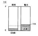
図3は、図1に示した表示部70の表示構成を示した図である。図3を参照して、表示部70は、走行用エネルギー残量表示部110と、補機蓄電残量表示部120とを含む。走行用エネルギー残量表示部110は、燃料残量表示部112と、蓄電残量表示部114とから成る。 FIG. 3 is a diagram showing a display configuration of the
燃料残量表示部112は、ECU60(図1)から燃料残量の検出値を受け、燃料満タン時(F)に対する燃料残量を表示する。蓄電残量表示部114は、ECU60から蓄電装置B1の蓄電残量を受け、蓄電装置B1の満充電時(F)に対する蓄電残量を表示する。点線で示されるしきい値116は、燃料残量および蓄電残量の低下を示す値であり、燃料残量および/または蓄電残量がしきい値116を下回ると、後述のように警告表示がなされる。なお、燃料満タン時(F)に対する燃料残量の低下を示すしきいレベルと蓄電装置B1の満充電時(F)に対する蓄電残量の低下を示すしきいレベルとは、互いに異なってもよい。補機蓄電残量表示部120は、ECU60から補機用蓄電装置B2の蓄電残量を受け、補機用蓄電装置B2の満充電時(F)に対する蓄電残量を表示する。 The fuel remaining
図4〜図6は、燃料タンク5の燃料残量および蓄電装置B1の蓄電残量の少なくとも一方が低下した場合の走行用エネルギー残量表示部110の表示状態を示した図である。図4を参照して、蓄電装置B1の蓄電残量が低下してしきい値116を下回ると、蓄電残量表示部114が点滅し、蓄電装置B1の蓄電残量の低下が利用者に対して警告される。 4 to 6 are diagrams showing display states of the traveling energy remaining
一方、図5を参照して、燃料タンク5の燃料残量が低下してしきい値116を下回ると、燃料残量表示部112が点滅し、燃料残量の低下が利用者に対して警告される。さらに、図6を参照して、燃料タンク5の燃料残量および蓄電装置B1の蓄電残量の双方が低下してしきい値116を下回ると、燃料残量表示部112および蓄電残量表示部114の双方が点滅し、燃料残量および蓄電装置B1の蓄電残量の双方の低下が利用者に対して警告される。 On the other hand, referring to FIG. 5, when the remaining amount of fuel in the
このように、燃料残量および蓄電装置B1の蓄電残量のいずれか一方が低下すると、その低下した方に対応する表示のみが点滅し、燃料残量および蓄電装置B1の蓄電残量の双方が低下すると、双方の表示が点滅する。 As described above, when either one of the remaining amount of fuel and the remaining amount of electricity stored in the power storage device B1 decreases, only the display corresponding to the decreased amount blinks, and both the remaining amount of fuel and the remaining power storage amount of the power storage device B1 are displayed. When it drops, both displays blink.
なお、燃料残量および蓄電装置B1の蓄電残量のいずれか一方のみが低下した場合には、警告を行なわないようにしてもよい。本実施例のように走行駆動用のエネルギー源として燃料および電力が外部から補給されるハイブリッド車両においては、燃料残量および蓄電残量のいずれか一方が低下しても他方の残量が低下していなければ、まだ十分な距離を走行することができるからである。たとえば、燃料補給を行なう意思のない利用者(EVモードでの走行を好む利用者)にとって燃料残量低下の警告は不要と考えられるので、燃料残量のみが低下しても燃料残量表示部112を点滅させず、燃料残量および蓄電装置B1の蓄電残量の双方が低下したときにはじめて燃料残量表示部112および蓄電残量表示部114の双方を点滅させるようにしてもよい。 Note that when only one of the remaining amount of fuel and the remaining amount of electricity stored in the electricity storage device B1 is lowered, the warning may not be performed. In a hybrid vehicle in which fuel and electric power are replenished from the outside as an energy source for driving driving as in the present embodiment, the remaining amount of the other is reduced even if either the remaining amount of fuel or the remaining amount of stored electricity is reduced. If not, it is still possible to travel a sufficient distance. For example, since it is considered unnecessary for a user who does not intend to refuel (a user who likes to travel in the EV mode) to warn of a decrease in the remaining amount of fuel, even if only the remaining amount of fuel decreases, the remaining fuel amount display section It is also possible to cause both the remaining fuel
また、燃料残量および蓄電装置B1の蓄電残量のいずれか一方のみが低下している場合、燃料残量および蓄電残量に応じた総走行可能距離が規定値を下回っている場合に限り、燃料残量表示部112および蓄電残量表示部114の双方を点滅させるようにしてもよい。 In addition, when only one of the remaining amount of fuel and the remaining amount of electricity stored in the electricity storage device B1 is reduced, only when the total travelable distance according to the remaining amount of fuel and the remaining amount of electricity stored is less than the specified value, You may make it blink both the fuel residual
再び図1を参照して、この場合、ECU60は、燃料タンク5の燃料残量に応じた走行可能距離および蓄電装置B1の蓄電残量に応じた走行可能距離を算出し、燃料残量および蓄電装置B1の蓄電残量に応じた総走行可能距離を算出する。そして、ECU60は、その算出された総走行可能距離が規定値を下回っているとき、その旨の通知を表示部70へ出力する。 Referring to FIG. 1 again, in this case,
そして、図7に示すように、燃料残量が低下している場合、蓄電装置B1の蓄電残量はしきい値116を下回っていないけれども燃料残量および蓄電装置B1の蓄電残量に応じた総走行可能距離が規定値を下回っているときは、表示部70は、ECU60からの通知に基づいて、燃料残量表示部112および蓄電残量表示部114の双方を点滅させる。 As shown in FIG. 7, when the remaining amount of fuel is decreasing, the remaining amount of power stored in power storage device B1 is not lower than
また、図8に示すように、燃料残量および蓄電装置B1の蓄電残量のいずれか一方が低下しても、燃料残量および蓄電残量に応じた総走行可能距離が規定値を超えている場合には、燃料残量表示部112および蓄電残量表示部114を点滅させないようにしてもよい。この場合にも、燃料残量および蓄電装置B1の蓄電残量に応じた総走行可能距離がECU60により算出され、その算出された総走行可能距離が規定値を超えているか否かがECU60から表示部70へ通知される。 Further, as shown in FIG. 8, even if either the remaining amount of fuel or the remaining amount of electricity stored in power storage device B1 decreases, the total travelable distance according to the remaining amount of fuel and the remaining amount of electricity stored exceeds the specified value. If there is, the remaining fuel
次に、外部電源80から蓄電装置B1の充電が行なわれるときのインバータ20,30の動作について説明する。 Next, the operation of
図9は、図1に示したインバータ20,30およびモータジェネレータMG1,MG2の零相等価回路を示した図である。三相ブリッジ回路から成る各インバータ20,30においては、6個のスイッチング素子のオン/オフの組合わせは8パターン存在する。その8つのスイッチングパターンのうち2つは相間電圧が零となり、そのような電圧状態は零電圧ベクトルと称される。零電圧ベクトルについては、上アームの3つのスイッチング素子は互いに同じスイッチング状態(全てオンまたはオフ)とみなすことができ、また、下アームの3つのスイッチング素子も互いに同じスイッチング状態とみなすことができる。したがって、この図9では、インバータ20の上アームの3つのスイッチング素子は上アーム20Aとしてまとめて示され、インバータ20の下アームの3つのスイッチング素子は下アーム20Bとしてまとめて示されている。同様に、インバータ30の上アームの3つのスイッチング素子は上アーム30Aとしてまとめて示され、インバータ30の下アームの3つのスイッチング素子は下アーム30Bとしてまとめて示されている。 FIG. 9 is a diagram showing a zero-phase equivalent circuit of
図9に示されるように、この零相等価回路は、電力線ACL1,ACL2を介して中性点N1,N2に与えられる単相交流電力を入力とする単相PWMコンバータとみることができる。そこで、インバータ20,30の各々において零電圧ベクトルを変化させ、インバータ20,30を単相PWMコンバータのアームとして動作するようにスイッチング制御することによって、電力線ACL1,ACL2から入力される外部電源80からの交流電力を直流電力に変換して正極線PL2および負極線NL2へ出力し、蓄電装置B1(図示せず)を充電することができる。 As shown in FIG. 9, this zero-phase equivalent circuit can be regarded as a single-phase PWM converter that receives single-phase AC power applied to neutral points N1 and N2 via power lines ACL1 and ACL2. Therefore, by changing the zero voltage vector in each of
なお、上記においては、表示部70における警告方法は、燃料残量表示部112および蓄電残量表示部114を点滅表示させるものとしたが、点滅表示に代えて表示色を変更するようにしてもよい。また、表示に代えて音声による警告としてもよい。 In the above description, the warning method on the
以上のように、この実施の形態1においては、車両走行用のエネルギー源として、燃料と蓄電装置B1に蓄えられた電力とを有するので、燃料残量および蓄電装置B1の蓄電残量のいずれか一方が低下しても十分な距離を走行できる。そして、表示部70は、燃料残量表示部112と蓄電残量表示部114とを含み、燃料残量および蓄電残量のいずれか一方が低下した場合と双方が低下した場合とで警告方法の態様を変更するので、燃料残量および蓄電残量のいずれか一方が低下しているけれどもまだ十分走行可能な場合と、燃料補給および蓄電装置B1の充電の少なくとも一方を行なう必要がある場合とが区別されて利用者に警告される。したがって、この実施の形態1によれば、走行用エネルギー残量の低下を利用者に対して適切に警告することができる。 As described above, in the first embodiment, since the fuel and the electric power stored in power storage device B1 are used as the energy source for vehicle travel, either the remaining amount of fuel or the remaining power storage amount of power storage device B1 is used. Even if one of them falls, it can travel a sufficient distance. The
[実施の形態1の変形例1]
図10は、実施の形態1の変形例1によるハイブリッド車両の全体ブロック図である。図10を参照して、このハイブリッド車両100Aは、図1に示したハイブリッド車両100の構成において、入力装置75をさらに備える。[
FIG. 10 is an overall block diagram of a hybrid vehicle according to the first modification of the first embodiment. Referring to FIG. 10,
入力装置75は、図4〜図8に示した走行用エネルギー残量表示部110における警告表示の態様を利用者が選択するための装置である。入力装置75は、利用者により設定された警告表示モードに応じた信号をECU60へ出力する。そして、ECU60は、入力装置75から受ける信号に応じて表示部70における警告表示を制御する。 The
具体的には、たとえば、燃料給油を行なわない利用者(EVモードでの走行を好む利用者)は、燃料残量のみが低下しても燃料残量表示部112が点滅しないように入力装置75から設定することができる。また、外部電源80から蓄電装置B1の充電を行なわない利用者(HVモードでの走行を好む利用者)は、蓄電装置B1の充電残量のみが低下しても蓄電残量表示部114が点滅しないように入力装置75から設定することができる。 Specifically, for example, a user who does not refuel (a user who prefers to travel in the EV mode) inputs the
以上のように、この実施の形態1の変形例1によれば、燃料補給を行なわない利用者や外部電源80から蓄電装置B1の充電を行なわない利用者の好みに合わせて、表示部70における警告表示の態様を利用者が選択することができる。 As described above, according to the first modification of the first embodiment, according to the preference of a user who does not refuel or a user who does not charge power storage device B1 from
[実施の形態2]
実施の形態1では、走行用エネルギー残量表示部110の燃料残量表示部112および蓄電残量表示部114は、同じ高さで併設されている。一方、燃料の有するエネルギー量と蓄電装置B1に蓄えられた電力の有するエネルギー量とは同じではない。たとえば、燃料残量および蓄電装置B1の蓄電残量の各々が満量に対して1/2であっても、燃料残量に応じた走行可能距離と蓄電残量に応じた走行可能距離とは等しくない。そこで、この実施の形態2では、燃料残量と蓄電残量とが同じ状態量(走行可能距離)に変換されて表示部に表示される。[Embodiment 2]
In the first embodiment, the remaining fuel
この実施の形態2によるハイブリッド車両の全体構成は、図1に示した実施の形態1によるハイブリッド車両100と同じである。そして、実施の形態2におけるECU60Aは、燃料残量センサ14から受ける燃料タンク5の燃料残量に応じた走行可能距離を算出し、その算出値を表示部70Aへ出力する。また、ECU60Aは、蓄電装置B1の蓄電残量に応じた走行可能距離を算出し、その算出値を表示部70Aへ出力する。すなわち、ECU60Aは、燃料残量および蓄電装置B1の蓄電残量の各々を走行可能距離に換算して表示部70Aへ出力する。 The overall configuration of the hybrid vehicle according to the second embodiment is the same as that of
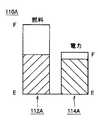
図11は、実施の形態2における表示部70Aの走行用エネルギー残量表示部の表示状態を示した図である。図11を参照して、走行用エネルギー残量表示部110Aは、燃料残量表示部112Aと、蓄電残量表示部114Aとから成る。燃料残量表示部112Aおよび蓄電残量表示部114Aは、隣接して配置され、燃料残量表示部112Aにおいて燃料残量が零であることを示す基準線と蓄電残量表示部114Aにおいて蓄電残量が零であることを示す基準線とが同一線上に配置される。そして、燃料残量表示部112Aおよび蓄電残量表示部114Aは、燃料満タン時の走行可能距離と蓄電装置B1が満充電時の走行可能距離との比率に応じた表示スケールで燃料残量および蓄電装置B1の蓄電残量をそれぞれ表示する。 FIG. 11 is a diagram showing a display state of the traveling energy remaining amount display portion of
より具体的には、燃料残量表示部112Aは、燃料タンク5の燃料残量に応じた走行可能距離を燃料満量状態からの乖離量を示しつつ表示する。また、蓄電残量表示部114Aは、蓄電装置B1の蓄電残量に応じた走行可能距離を満充電状態からの乖離量を示しつつ表示する。 More specifically, the remaining fuel
以上のように、この実施の形態2においては、燃料残量表示部112Aおよび蓄電残量表示部114Aは、それぞれ燃料残量および蓄電装置B1の蓄電残量を同じ状態量(走行可能距離)に換算して表示するので、表示された燃料残量および蓄電残量から燃料残量および蓄電残量間のエネルギー比が把握可能である。したがって、この実施の形態2によれば、燃料残量および蓄電残量とともに、燃料残量および蓄電残量間のエネルギー比を直感的に把握することができる。 As described above, in the second embodiment, the remaining fuel
[実施の形態2の変形例1]
図12は、実施の形態2の変形例1における走行用エネルギー残量表示部の表示状態を示した図である。図12を参照して、走行用エネルギー残量表示部110Bは、燃料残量表示部112Bと、蓄電残量表示部114Bとから成る。燃料残量表示部112Bおよび蓄電残量表示部114Bは、同一軸上に配置され、共通の基準線を零点として互いに逆方向に燃料残量および蓄電装置B1の蓄電残量を表示する。[
FIG. 12 is a diagram showing a display state of the traveling energy remaining amount display section in the first modification of the second embodiment. Referring to FIG. 12, traveling energy remaining
そして、燃料残量表示部112Bおよび蓄電残量表示部114Bは、燃料満タン時の走行可能距離と蓄電装置B1が満充電時の走行可能距離との比率に応じた表示スケールで燃料残量および蓄電装置B1の蓄電残量をそれぞれ表示する。より具体的には、燃料残量表示部112Bは、燃料タンク5の燃料残量に応じた走行可能距離を燃料満量状態からの乖離量を示しつつ表示し、蓄電残量表示部114Bは、蓄電装置B1の蓄電残量に応じた走行可能距離を満充電状態からの乖離量を示しつつ表示する。 The remaining fuel
この実施の形態2の変形例1によれば、燃料残量および蓄電残量間のエネルギー比を直感的に把握可能であるとともに、燃料残量および蓄電残量による総走行可能距離をより直感的に把握することができる。 According to the first modification of the second embodiment, it is possible to intuitively grasp the energy ratio between the remaining amount of fuel and the remaining amount of electricity stored, and more intuitively determine the total travelable distance based on the remaining amount of fuel and the remaining amount of electricity stored. Can grasp.
[実施の形態2の変形例2]
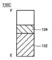
図13は、実施の形態2の変形例2における走行用エネルギー残量表示部の表示状態を示した図である。図13を参照して、走行用エネルギー残量表示部110Cは、燃料満タン時の走行可能距離と蓄電装置B1が満充電時の走行可能距離との総和をフルスケールとして、燃料残量に応じた走行可能距離と蓄電残量に応じた走行可能距離とを積層して表示する。すなわち、走行用エネルギー残量表示部110Cは、燃料残量に応じた走行可能距離を領域132に表示し、蓄電残量に応じた走行可能距離を領域134に表示する。[
FIG. 13 is a diagram showing a display state of the travel energy remaining amount display section in the second modification of the second embodiment. Referring to FIG. 13, traveling energy remaining
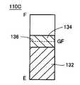
なお、図14に示すように、燃料満タン時の走行可能距離を示すレベル値136を走行用エネルギー残量表示部110Cに表示してもよい。 As shown in FIG. 14, the
この実施の形態2の変形例2によれば、燃料残量および蓄電装置B1の蓄電残量に応じた総走行可能距離を直感的に把握することができる。 According to the second modification of the second embodiment, the total travelable distance according to the remaining fuel amount and the remaining power storage amount of the power storage device B1 can be intuitively grasped.
[実施の形態2の変形例3]
図15は、実施の形態2の変形例3における走行用エネルギー残量表示部の表示状態を示した図である。図15を参照して、走行用エネルギー残量表示部110Dは、燃料残量表示部112Cと、蓄電残量表示部114Cとから成る。[Modification 3 of Embodiment 2]
FIG. 15 is a diagram showing a display state of the travel energy remaining amount display section in the third modification of the second embodiment. Referring to FIG. 15, traveling energy remaining
燃料残量表示部112Cは、燃料タンク5の燃料残量に応じた走行可能距離を燃料満量状態からの乖離量を示しつつ表示する。蓄電残量表示部114Cは、蓄電装置B1の蓄電残量に応じた走行可能距離を満充電状態からの乖離量を示しつつ表示する。そして、燃料残量表示部112Cおよび蓄電残量表示部114Cは、同一軸上に積層して配置される。すなわち、この走行用エネルギー残量表示部110Dは、図11に示した走行用エネルギー残量表示部110Aにおいて、燃料残量表示部と蓄電残量表示部とを同一軸上で同方向に積層して配置したものに相当する。 The remaining fuel
この実施の形態2の変形例3によっても、燃料残量および蓄電残量とともに、燃料残量および蓄電残量間のエネルギー比を直感的に把握することができる。 Also according to the third modification of the second embodiment, the energy ratio between the remaining fuel amount and the remaining power amount can be intuitively grasped together with the remaining fuel amount and the remaining power amount.
[実施の形態2の変形例4]
図16は、実施の形態2の変形例4における走行用エネルギー残量表示部の表示状態を示した図である。図16を参照して、この走行用エネルギー残量表示部110Eは、図13に示した変形例2における走行用エネルギー残量表示部110Cの表示構成において、燃料残量メモリ138と、蓄電残量メモリ140とをさらに含む。[
FIG. 16 is a diagram showing a display state of the travel energy remaining amount display section in the fourth modification of the second embodiment. Referring to FIG. 16, this traveling energy remaining
燃料残量メモリ138は、燃料残量に応じた走行可能距離が表示される領域132に隣接して表示され、燃料残量に応じた走行可能距離が零に相当するレベル(GE)と満タン状態に相当するレベル(GF)とを示す。 The fuel remaining
また、蓄電残量メモリ140は、蓄電残量に応じた走行可能距離が表示される領域134に隣接して表示される。そして、蓄電残量メモリ140は、燃料残量に応じて変動する領域134に連動し、蓄電残量に応じた走行可能距離が零に相当するレベル(PE)と満充電状態に相当するレベル(PF)とを示す。 Further, the remaining
この実施の形態2の変形例4によれば、燃料残量および蓄電残量に応じた総走行可能距離を直感的に把握可能であるとともに、燃料満タン時に対する燃料残量および蓄電装置B1の満充電状態に対する蓄電残量を同時に把握することができる。 According to the fourth modification of the second embodiment, the total travelable distance according to the remaining fuel amount and the remaining power storage amount can be intuitively grasped, and the remaining fuel amount and the power storage device B1 when the fuel is full are stored. It is possible to simultaneously grasp the remaining amount of electricity stored in the fully charged state.
なお、上記の実施の形態2およびその変形例1〜4においては、燃料残量および蓄電残量を同一の状態量としての走行可能距離に換算して表示部に表示するものとしたが、燃料残量および蓄電残量を同一のエネルギー量(J)に単位換算して表示部に表示してもよい。この表示によっても、燃料補給および蓄電装置B1の充電のいずれを行なうべきかを直感的に判断することが可能である。 In the second embodiment and the first to fourth modifications thereof, the remaining fuel amount and the remaining power storage amount are converted to the travelable distance as the same state quantity and displayed on the display unit. The remaining amount and the remaining power storage amount may be converted into the same energy amount (J) and displayed on the display unit. This display also makes it possible to intuitively determine whether to refuel or charge the power storage device B1.
なお、上記の各実施の形態においては、外部電源80から蓄電装置B1の充電が行なわれるとき、モータジェネレータMG1,MG2の中性点N1,N2から充電電力を入力するものとしたが、充電用の専用インバータを別途設けてもよい。 In each of the above embodiments, when power storage device B1 is charged from
図17は、充電用インバータを別途備えたハイブリッド車両の全体ブロック図である。図17を参照して、ハイブリッド車両100Bは、図1に示したハイブリッド車両100の構成において充電用インバータ90をさらに備える。 FIG. 17 is an overall block diagram of a hybrid vehicle separately provided with a charging inverter. Referring to FIG. 17,
充電用インバータ90は、正極線PL2および負極線NL2に接続され、ECU60からの信号PWMI3に基づいて、外部電源80から充電プラグ40に与えられる交流電力を直流電力に変換して正極線PL2および負極線NL2へ出力する。 Charging
そして、充電用インバータ90から供給される直流電力を昇圧コンバータ10により蓄電装置B1の電圧レベルに変換して蓄電装置B1を充電することができる。なお、ハイブリッド車両100Bのその他の構成は、ハイブリッド車両100と同じである。 Then, DC power supplied from charging
なお、上記の各実施の形態においては、外部電源80から蓄電装置B1を充電可能なハイブリッド車両について説明したが、この発明の適用範囲は、そのような外部充電機能を有するハイブリッド車両に限定されるものではない。但し、外部充電機能を有するハイブリッド車両においては、上述のように、燃料残量とともに蓄電装置B1の蓄電残量を利用者に表示し、かつ、燃料残量および/または蓄電残量が低下したときに利用者に対して適切に警告を発することが特に要請されると考えられるので、この発明は、外部充電機能を有するハイブリッド車両に特に好適である。 In each of the above embodiments, a hybrid vehicle that can charge power storage device B1 from
また、上記においては、動力分割機構3によりエンジン4の動力を車軸とモータジェネレータMG1とに分割して伝達可能なシリーズ/パラレル型のハイブリッド車両について説明したが、この発明は、その他の形式のハイブリッド車両にも適用可能である。すなわち、たとえば、モータジェネレータMG1を駆動するためにのみエンジン4を用い、モータジェネレータMG2でのみ車両の駆動力を発生する、いわゆるシリーズ型のハイブリッド車両や、エンジン4が生成した運動エネルギーのうち回生エネルギーのみが電気エネルギーとして回収されるハイブリッド車両、エンジンを主動力として必要に応じてモータがアシストするモータアシスト型のハイブリッド車両などにもこの発明は適用可能である。 In the above description, the series / parallel type hybrid vehicle in which the power of the
すなわち、この発明は、内燃機関と蓄電装置と電動機とを有する車両であって、内燃機関による運動エネルギーを電気エネルギーとして蓄電した蓄電装置から電動機に供給される電力を動力源とする車両全般に適用可能である。 That is, this invention is a vehicle having an internal combustion engine, a power storage device, and an electric motor, and is applied to all vehicles that use electric power supplied to the motor from the power storage device that stores kinetic energy from the internal combustion engine as electric energy. Is possible.
なお、この発明は、昇圧コンバータ10を備えないハイブリッド車両にも適用可能である。 The present invention is also applicable to a hybrid vehicle that does not include
なお、上記において、エンジン4は、この発明における「内燃機関」の一実施例に対応し、蓄電装置B1は、この発明における「蓄電装置」の一実施例に対応する。また、充電プラグ40、電力線ACL1,ACL2、モータジェネレータMG1,MG2およびインバータ20,30は、この発明における「充電装置」の一実施例を構成し、充電プラグ40および充電用インバータ90も、この発明における「充電装置」の一実施例を構成する。さらに、モータジェネレータMG2は、この発明における「電動機」の一実施例に対応し、ECU60および表示部70は、この発明における「告知装置」の一実施例を構成する。 In the above,
また、さらに、ECU60Aおよび表示部70Aは、この発明における「表示装置」の一実施例を構成する。また、さらに、燃料残量表示部112A(112B,112C)は、この発明における「第1の表示部」の一実施例に対応し、蓄電残量表示部114A(114B,114C)は、この発明における「第2の表示部」の一実施例に対応する。また、さらに、領域132は、この発明における「第1の表示領域」の一実施例に対応し、燃料残量メモリ138は、この発明における「第1の表示メモリ」の一実施例に対応する。また、さらに、領域134は、この発明における「第2の表示領域」の一実施例に対応し、蓄電残量メモリ140は、この発明における「第2の表示メモリ」の一実施例に対応する。 Furthermore,
今回開示された実施の形態は、すべての点で例示であって制限的なものではないと考えられるべきである。本発明の範囲は、上記した実施の形態の説明ではなくて特許請求の範囲によって示され、特許請求の範囲と均等の意味および範囲内でのすべての変更が含まれることが意図される。 The embodiment disclosed this time should be considered as illustrative in all points and not restrictive. The scope of the present invention is shown not by the above description of the embodiment but by the scope of claims for patent, and is intended to include all modifications within the meaning and scope equivalent to the scope of claims for patent.
2 車輪、3 動力分割機構、4 エンジン、5 燃料タンク、7,8 三相コイル、10 昇圧コンバータ、12 燃料補給口、14 燃料残量センサ、20,30 インバータ、20A,30A 上アーム、20B,30B 下アーム、40 充電プラグ、50 DC/DCコンバータ、60,60A ECU、70,70A 表示部、72 電圧センサ、74 電流センサ、75 入力装置、80 外部電源、90 充電用インバータ、100,100A,100B ハイブリッド車両、110,110A〜110E 走行用エネルギー残量表示部、112,112A〜112C 燃料残量表示部、114,114A〜114C 蓄電残量表示部、116 しきい値、120 補機蓄電残量表示部、132,134 領域、138 燃料残量メモリ、140 蓄電残量メモリ、B1 蓄電装置、B2 補機用蓄電装置、SMR システムメインリレー、PL1,PL2 正極線、NL1,NL2 負極線、C1,C2 コンデンサ、MG1,MG2 モータジェネレータ、N1,N2 中性点、ACL1,ACL2 電力線。 2 wheels, 3 power split mechanism, 4 engine, 5 fuel tank, 7, 8 three-phase coil, 10 boost converter, 12 fuel supply port, 14 remaining fuel sensor, 20, 30 inverter, 20A, 30A upper arm, 20B, 30B Lower arm, 40 Charging plug, 50 DC / DC converter, 60, 60A ECU, 70, 70A Display unit, 72 Voltage sensor, 74 Current sensor, 75 Input device, 80 External power supply, 90 Charging inverter, 100, 100A, 100B Hybrid vehicle, 110, 110A to 110E Remaining energy display section for travel, 112, 112A to 112C Remaining fuel display section, 114, 114A to 114C Remaining power display section, 116 threshold, 120 Auxiliary power storage capacity Display section, 132, 134 area, 138 Fuel remaining amount memory, 14 Remaining power storage memory, B1 power storage device, B2 Auxiliary power storage device, SMR system main relay, PL1, PL2 positive line, NL1, NL2 negative line, C1, C2 capacitor, MG1, MG2 motor generator, N1, N2 neutral point , ACL1, ACL2 power lines.
Claims (16)
Translated fromJapanese充放電可能な蓄電装置と、
車両外部から供給される電力を受けて前記蓄電装置を充電可能に構成された充電装置と、
前記蓄電装置から電力の供給を受けて車両走行用の駆動力を発生する電動機と、
前記内燃機関の燃料残量および前記蓄電装置の蓄電残量を告知するとともに、前記燃料残量および前記蓄電残量の少なくとも一方が低下したときに利用者に対して警告可能なように構成された告知装置とを備え、
前記告知装置は、前記燃料残量および前記蓄電残量のいずれか一方が低下した場合と前記燃料残量および前記蓄電残量の双方が低下した場合とで利用者に対する警告方法の態様を変更する、ハイブリッド車両。An internal combustion engine;
A chargeable / dischargeable power storage device;
A charging device configured to receive power supplied from outside the vehicle and charge the power storage device;
An electric motor that receives a supply of electric power from the power storage device and generates a driving force for traveling the vehicle;
The fuel remaining amount of the internal combustion engine and the remaining amount of electricity stored in the power storage device are notified, and at least one of the remaining amount of fuel and the remaining amount of stored electricity can be warned to the user. A notification device,
The notification device changes a mode of a warning method for a user when either one of the remaining fuel amount and the remaining power storage amount decreases and when both the remaining fuel amount and the remaining power storage amount decrease. , Hybrid vehicle.
充放電可能な蓄電装置と、
車両外部から供給される電力を受けて前記蓄電装置を充電可能に構成された充電装置と、
前記蓄電装置から電力の供給を受けて車両走行用の駆動力を発生する電動機と、
前記内燃機関の燃料残量および前記蓄電装置の蓄電残量を告知するとともに、前記燃料残量および前記蓄電残量の少なくとも一方が低下したときに利用者に対して警告可能なように構成された告知装置と、
前記燃料残量が低下した場合の利用者に対する警告方法と前記蓄電残量が低下した場合の利用者に対する警告方法とを利用者が設定可能な入力装置とを備えるハイブリッド車両。An internal combustion engine;
A chargeable / dischargeable power storage device;
A charging device configured to receive power supplied from outside the vehicle and charge the power storage device;
An electric motor that receives a supply of electric power from the power storage device and generates a driving force for traveling the vehicle;
The fuel remaining amount of the internal combustion engine and the remaining amount of electricity stored in the power storage device are notified, and at least one of the remaining amount of fuel and the remaining amount of stored electricity can be warned to the user. A notification device;
A hybrid vehicle comprising: an input device that allows a user to set a warning method for a user when the remaining fuel amount decreases and a warning method for a user when the remaining power amount decreases.
前記告知装置は、前記補機用蓄電装置の蓄電残量をさらに告知する、請求項1または請求項2に記載のハイブリッド車両。Further comprising an auxiliary power storage device different from the power storage device,
The hybrid vehicle according to claim 1, wherein the notification device further notifies the remaining power storage amount of the auxiliary power storage device.
充放電可能な蓄電装置と、
前記蓄電装置と異なる補機用蓄電装置と、
車両外部から供給される電力を受けて前記蓄電装置を充電可能に構成された充電装置と、
前記蓄電装置から電力の供給を受けて車両走行用の駆動力を発生する電動機と、
前記蓄電装置の蓄電残量を告知するとともに、前記蓄電装置の蓄電残量が低下したときに利用者に対して警告を出力する告知装置とを備えるハイブリッド車両。An internal combustion engine;
A chargeable / dischargeable power storage device;
Auxiliary power storage device different from the power storage device,
A charging device configured to receive power supplied from outside the vehicle and charge the power storage device;
An electric motor that receives a supply of electric power from the power storage device and generates a driving force for traveling the vehicle;
A hybrid vehicle comprising: a notification device that notifies the user of a remaining amount of electricity stored in the power storage device and outputs a warning to a user when the remaining amount of power stored in the power storage device decreases.
充放電可能な蓄電装置と、
車両外部から供給される電力を受けて前記蓄電装置を充電可能に構成された充電装置と、
前記蓄電装置から電力の供給を受けて車両走行用の駆動力を発生する電動機と、
前記内燃機関の燃料残量および前記蓄電装置の蓄電残量を表示する表示装置とを備え、
前記表示装置は、
前記燃料残量を所定の状態量に換算して燃料満量状態からの乖離量を示しつつ表示する第1の表示部と、
前記蓄電残量を前記所定の状態量に換算して満充電状態からの乖離量を示しつつ表示する第2の表示部とを含む、ハイブリッド車両。An internal combustion engine;
A chargeable / dischargeable power storage device;
A charging device configured to receive power supplied from outside the vehicle and charge the power storage device;
An electric motor that receives a supply of electric power from the power storage device and generates a driving force for traveling the vehicle;
A display device for displaying a remaining fuel amount of the internal combustion engine and a remaining power amount of the power storage device,
The display device
A first display unit that converts the remaining fuel amount into a predetermined state amount and displays the amount of deviation from the fuel full state;
A hybrid vehicle comprising: a second display unit that converts the remaining amount of electricity storage into the predetermined state amount and displays the amount of deviation from the fully charged state.
燃料満量状態に応じた走行可能距離と前記蓄電装置の満充電状態に応じた走行可能距離との比率に応じて、それぞれ前記第1および第2の表示部の相対的な表示長さまたは表示面積が設定される、請求項9に記載のハイブリッド車両。The first and second display units are arranged adjacent to each other,
Relative display lengths or displays of the first and second display units, respectively, according to the ratio of the travelable distance according to the fuel full state and the travelable distance according to the fully charged state of the power storage device The hybrid vehicle according to claim 9, wherein the area is set.
前記第1の表示部は、
前記燃料残量を表示する第1の表示領域と、
前記第1の表示領域に隣接して表示され、燃料満量状態に対する前記燃料残量の相対量を指示するための第1の表示メモリとから成り、
前記第2の表示部は、
前記蓄電残量を表示する第2の表示領域と、
前記第2の表示領域に隣接して表示され、前記蓄電装置の満充電状態に対する前記蓄電残量の相対量を指示するための第2の表示メモリとから成る、請求項8または請求項9に記載のハイブリッド車両。The remaining amount of fuel and the remaining amount of electricity stored are displayed stacked on the same axis,
The first display unit includes:
A first display area for displaying the remaining amount of fuel;
A first display memory which is displayed adjacent to the first display area and which indicates a relative amount of the remaining fuel amount with respect to a fuel full state;
The second display unit includes:
A second display area for displaying the remaining amount of electricity stored;
10. The display device according to claim 8, further comprising: a second display memory that is displayed adjacent to the second display area and that indicates a relative amount of the remaining power storage amount with respect to a fully charged state of the power storage device. The described hybrid vehicle.
充放電可能な蓄電装置と、
前記蓄電装置から電力の供給を受けて車両走行用の駆動力を発生する電動機と、
前記内燃機関の燃料残量および前記蓄電装置の蓄電残量を告知するとともに、前記燃料残量および前記蓄電残量の少なくとも一方が低下したときに利用者に対して警告可能なように構成された告知装置とを備え、
前記告知装置は、前記燃料残量および前記蓄電残量のいずれか一方が低下した場合と前記燃料残量および前記蓄電残量の双方が低下した場合とで利用者に対する警告方法の態様を変更する、ハイブリッド車両。An internal combustion engine;
A chargeable / dischargeable power storage device;
An electric motor that receives a supply of electric power from the power storage device and generates a driving force for traveling the vehicle;
The fuel remaining amount of the internal combustion engine and the remaining amount of electricity stored in the power storage device are notified, and at least one of the remaining amount of fuel and the remaining amount of stored electricity can be warned to the user. A notification device,
The notification device changes a mode of a warning method for a user when either one of the remaining fuel amount and the remaining power storage amount decreases and when both the remaining fuel amount and the remaining power storage amount decrease. , Hybrid vehicle.
充放電可能な蓄電装置と、
前記蓄電装置から電力の供給を受けて車両走行用の駆動力を発生する電動機と、
前記内燃機関の燃料残量および前記蓄電装置の蓄電残量を表示する表示装置とを備え、
前記表示装置は、
前記燃料残量を所定の状態量に換算して燃料満量状態からの乖離量を示しつつ表示する第1の表示部と、
前記蓄電残量を前記所定の状態量に換算して満充電状態からの乖離量を示しつつ表示する第2の表示部とを含む、ハイブリッド車両。An internal combustion engine;
A chargeable / dischargeable power storage device;
An electric motor that receives a supply of electric power from the power storage device and generates a driving force for traveling the vehicle;
A display device for displaying a remaining fuel amount of the internal combustion engine and a remaining power amount of the power storage device,
The display device
A first display unit that converts the remaining fuel amount into a predetermined state amount and displays the amount of deviation from the fuel full state;
A hybrid vehicle comprising: a second display unit that converts the remaining amount of electricity storage into the predetermined state amount and displays the amount of deviation from the fully charged state.
Priority Applications (1)
| Application Number | Priority Date | Filing Date | Title |
|---|---|---|---|
| JP2007088164AJP2008247081A (en) | 2007-03-29 | 2007-03-29 | Hybrid vehicle |
Applications Claiming Priority (1)
| Application Number | Priority Date | Filing Date | Title |
|---|---|---|---|
| JP2007088164AJP2008247081A (en) | 2007-03-29 | 2007-03-29 | Hybrid vehicle |
Publications (1)
| Publication Number | Publication Date |
|---|---|
| JP2008247081Atrue JP2008247081A (en) | 2008-10-16 |
Family
ID=39972555
Family Applications (1)
| Application Number | Title | Priority Date | Filing Date |
|---|---|---|---|
| JP2007088164APendingJP2008247081A (en) | 2007-03-29 | 2007-03-29 | Hybrid vehicle |
Country Status (1)
| Country | Link |
|---|---|
| JP (1) | JP2008247081A (en) |
Cited By (17)
| Publication number | Priority date | Publication date | Assignee | Title |
|---|---|---|---|---|
| WO2009031397A1 (en)* | 2007-09-06 | 2009-03-12 | Toyota Jidosha Kabushiki Kaisha | Hybrid vehicle |
| WO2010100736A1 (en)* | 2009-03-05 | 2010-09-10 | トヨタ自動車株式会社 | Charge/discharge control system for hybrid vehicle, and control method therefor |
| JP2011057116A (en)* | 2009-09-11 | 2011-03-24 | Toyota Motor Corp | Display device and hybrid vehicle equipped with the same |
| JP2011098638A (en)* | 2009-11-05 | 2011-05-19 | Toyota Motor Corp | Hybrid vehicle and control method |
| WO2011136076A1 (en)* | 2010-04-28 | 2011-11-03 | トヨタ自動車株式会社 | Hybrid vehicle control device and hybrid vehicle equipped with same |
| JP2012081834A (en)* | 2010-10-08 | 2012-04-26 | Toyota Motor Corp | Hybrid automobile and information output method |
| CN102741088A (en)* | 2011-01-06 | 2012-10-17 | 福特全球技术公司 | Information display system and method |
| WO2012175839A1 (en)* | 2011-06-21 | 2012-12-27 | Peugeot Citroen Automobiles Sa | Man/machine interface and display device for a hybrid motor vehicle |
| WO2013011596A1 (en)* | 2011-07-15 | 2013-01-24 | 三菱電機株式会社 | Vehicle charging system and vehicle charging method |
| WO2015005483A1 (en)* | 2013-07-11 | 2015-01-15 | 三菱自動車工業株式会社 | Possible travel distance calculation device |
| JP2015126657A (en)* | 2013-12-27 | 2015-07-06 | パナソニックIpマネジメント株式会社 | Power storage system |
| US9493150B2 (en) | 2010-04-07 | 2016-11-15 | Toyota Jidosha Kabushiki Kaisha | Control device for hybrid vehicle, and hybrid vehicle incorporating control device |
| CN110962598A (en)* | 2018-09-28 | 2020-04-07 | 本田技研工业株式会社 | Vehicle information display device |
| CN111332124A (en)* | 2020-04-04 | 2020-06-26 | 东风汽车集团有限公司 | Fuel cell system bleeder circuit based on two-stage protection |
| JP2020183204A (en)* | 2019-05-09 | 2020-11-12 | マツダ株式会社 | Meter display and vehicles equipped with it |
| CN112848930A (en)* | 2021-03-11 | 2021-05-28 | 深圳市福瑞电气有限公司 | Circuit and method for switching pure electric operation mode of hydrogen fuel cell automobile |
| CN113276695A (en)* | 2020-02-03 | 2021-08-20 | 丰田自动车株式会社 | Vehicle with a steering wheel |
Citations (2)
| Publication number | Priority date | Publication date | Assignee | Title |
|---|---|---|---|---|
| JPH07111702A (en)* | 1993-10-12 | 1995-04-25 | Honda Motor Co Ltd | Remote indicator of residual battery capacity of motor vehicle |
| JP2007068358A (en)* | 2005-09-01 | 2007-03-15 | Toyota Motor Corp | Electric vehicle |
- 2007
- 2007-03-29JPJP2007088164Apatent/JP2008247081A/enactivePending
Patent Citations (2)
| Publication number | Priority date | Publication date | Assignee | Title |
|---|---|---|---|---|
| JPH07111702A (en)* | 1993-10-12 | 1995-04-25 | Honda Motor Co Ltd | Remote indicator of residual battery capacity of motor vehicle |
| JP2007068358A (en)* | 2005-09-01 | 2007-03-15 | Toyota Motor Corp | Electric vehicle |
Cited By (32)
| Publication number | Priority date | Publication date | Assignee | Title |
|---|---|---|---|---|
| US8289143B2 (en) | 2007-09-06 | 2012-10-16 | Toyota Jidosha Kabushiki Kaisha | Hybrid vehicle |
| WO2009031397A1 (en)* | 2007-09-06 | 2009-03-12 | Toyota Jidosha Kabushiki Kaisha | Hybrid vehicle |
| WO2010100736A1 (en)* | 2009-03-05 | 2010-09-10 | トヨタ自動車株式会社 | Charge/discharge control system for hybrid vehicle, and control method therefor |
| JP4868088B2 (en)* | 2009-03-05 | 2012-02-01 | トヨタ自動車株式会社 | Charge / discharge control system and control method for hybrid vehicle |
| US8229616B2 (en) | 2009-03-05 | 2012-07-24 | Toyota Jidosha Kabushiki Kaisha | Charging/discharging control system for hybrid vehicle and method for controlling same |
| JP2011057116A (en)* | 2009-09-11 | 2011-03-24 | Toyota Motor Corp | Display device and hybrid vehicle equipped with the same |
| JP2011098638A (en)* | 2009-11-05 | 2011-05-19 | Toyota Motor Corp | Hybrid vehicle and control method |
| US9493150B2 (en) | 2010-04-07 | 2016-11-15 | Toyota Jidosha Kabushiki Kaisha | Control device for hybrid vehicle, and hybrid vehicle incorporating control device |
| US10065630B2 (en) | 2010-04-07 | 2018-09-04 | Toyota Jidosha Kabushiki Kaisha | Control device for hybrid vehicle, and hybrid vehicle incorporating control device |
| WO2011136076A1 (en)* | 2010-04-28 | 2011-11-03 | トヨタ自動車株式会社 | Hybrid vehicle control device and hybrid vehicle equipped with same |
| CN102958775A (en)* | 2010-04-28 | 2013-03-06 | 丰田自动车株式会社 | Hybrid vehicle control device and hybrid vehicle equipped with same |
| JP2011230662A (en)* | 2010-04-28 | 2011-11-17 | Toyota Motor Corp | Control device for hybrid vehicle and hybrid vehicle including the same |
| JP2012081834A (en)* | 2010-10-08 | 2012-04-26 | Toyota Motor Corp | Hybrid automobile and information output method |
| CN102741088A (en)* | 2011-01-06 | 2012-10-17 | 福特全球技术公司 | Information display system and method |
| CN102741088B (en)* | 2011-01-06 | 2016-05-04 | 福特全球技术公司 | Information Display System And Method |
| WO2012175839A1 (en)* | 2011-06-21 | 2012-12-27 | Peugeot Citroen Automobiles Sa | Man/machine interface and display device for a hybrid motor vehicle |
| FR2976889A1 (en)* | 2011-06-21 | 2012-12-28 | Peugeot Citroen Automobiles Sa | MAN INTERFACE / MACHINE OF A HYBRID MOTOR VEHICLE. |
| WO2013011596A1 (en)* | 2011-07-15 | 2013-01-24 | 三菱電機株式会社 | Vehicle charging system and vehicle charging method |
| US9242569B2 (en) | 2011-07-15 | 2016-01-26 | Mitsubishi Electric Corporation | Vehicle charge system and vehicle charge method |
| JP2015016811A (en)* | 2013-07-11 | 2015-01-29 | 三菱自動車エンジニアリング株式会社 | Driving distance calculation device |
| US9758045B2 (en) | 2013-07-11 | 2017-09-12 | Mitsubishi Jidosha Kogyo Kabushiki Kaisha | Travelable distance calculation apparatus |
| WO2015005483A1 (en)* | 2013-07-11 | 2015-01-15 | 三菱自動車工業株式会社 | Possible travel distance calculation device |
| JP2015126657A (en)* | 2013-12-27 | 2015-07-06 | パナソニックIpマネジメント株式会社 | Power storage system |
| CN110962598A (en)* | 2018-09-28 | 2020-04-07 | 本田技研工业株式会社 | Vehicle information display device |
| JP2020183204A (en)* | 2019-05-09 | 2020-11-12 | マツダ株式会社 | Meter display and vehicles equipped with it |
| CN113276695A (en)* | 2020-02-03 | 2021-08-20 | 丰田自动车株式会社 | Vehicle with a steering wheel |
| JP2021123176A (en)* | 2020-02-03 | 2021-08-30 | トヨタ自動車株式会社 | vehicle |
| JP7310630B2 (en) | 2020-02-03 | 2023-07-19 | トヨタ自動車株式会社 | vehicle |
| CN113276695B (en)* | 2020-02-03 | 2023-10-03 | 丰田自动车株式会社 | Vehicle with a vehicle body having a vehicle body support |
| CN111332124A (en)* | 2020-04-04 | 2020-06-26 | 东风汽车集团有限公司 | Fuel cell system bleeder circuit based on two-stage protection |
| CN111332124B (en)* | 2020-04-04 | 2021-09-10 | 东风汽车集团有限公司 | Fuel cell system bleeder circuit based on two-stage protection |
| CN112848930A (en)* | 2021-03-11 | 2021-05-28 | 深圳市福瑞电气有限公司 | Circuit and method for switching pure electric operation mode of hydrogen fuel cell automobile |
Similar Documents
| Publication | Publication Date | Title |
|---|---|---|
| JP2008247081A (en) | Hybrid vehicle | |
| US7933695B2 (en) | Electric vehicle power source selection | |
| JP4910917B2 (en) | HYBRID VEHICLE, HYBRID VEHICLE CONTROL METHOD, AND COMPUTER-READABLE RECORDING MEDIUM CONTAINING PROGRAM FOR CAUSING COMPUTER TO EXECUTE THE CONTROL METHOD | |
| JP4211860B2 (en) | ELECTRIC VEHICLE CHARGE CONTROL DEVICE, ELECTRIC VEHICLE, ELECTRIC VEHICLE CHARGE CONTROL METHOD, AND COMPUTER-READABLE RECORDING MEDIUM CONTAINING PROGRAM FOR CAUSING COMPUTER TO EXECUTE THE CHARGE CONTROL | |
| JP6130634B2 (en) | Apparatus and method for charging an electric vehicle | |
| JP5024454B2 (en) | Electric vehicle power supply system and control method thereof | |
| JP6194164B2 (en) | Apparatus and method for quickly charging an electric vehicle | |
| JP5099230B2 (en) | Electric vehicle power supply system and control method thereof | |
| CN101516700B (en) | Display device for hybrid vehicle, hybrid vehicle, and display method for hybrid vehicle | |
| JP4962184B2 (en) | Vehicle power supply | |
| CN102202930B (en) | Electric vehicle and control method for electric vehicle | |
| US8538616B2 (en) | Power supply system for electrically powered vehicle, electrically powered vehicle, and method for controlling the same | |
| JP2008247080A (en) | Hybrid vehicle display system | |
| CN102458907A (en) | Power supply system for electric vehicle and control method thereof | |
| JP2008087516A (en) | Hybrid vehicle and drive control method of the same | |
| WO2008065837A1 (en) | Hybrid vehicle, control method of hybrid vehicle and computer readable recording medium recording program for making computer execute that control method | |
| WO2010143279A1 (en) | Power supply system for electric vehicle, electric vehicle, and control method of power supply system for electric vehicle | |
| JP2008230409A (en) | Hybrid vehicle and control method of hybrid vehicle | |
| JP5205962B2 (en) | Battery capacity determination support system and battery capacity determination support method | |
| JP2007274785A (en) | Vehicle drive power supply system | |
| JP4877047B2 (en) | Hybrid vehicle | |
| JP2013158082A (en) | Vehicle and method for controlling vehicle | |
| JP2009042157A (en) | Electric vehicle, storage device deterioration detection method, and computer-readable recording medium storing a program for causing a computer to execute the deterioration detection method | |
| JP5155916B2 (en) | Electric vehicle | |
| JP2007274840A (en) | Power supply device and control method of power supply device |
Legal Events
| Date | Code | Title | Description |
|---|---|---|---|
| A621 | Written request for application examination | Free format text:JAPANESE INTERMEDIATE CODE: A621 Effective date:20090416 | |
| A131 | Notification of reasons for refusal | Free format text:JAPANESE INTERMEDIATE CODE: A131 Effective date:20101207 | |
| A521 | Written amendment | Free format text:JAPANESE INTERMEDIATE CODE: A523 Effective date:20110202 | |
| A02 | Decision of refusal | Free format text:JAPANESE INTERMEDIATE CODE: A02 Effective date:20110322 |