JP2008246061A - System for processing fraudulent putout of token, method for processing fraudulent putout of token and game machine - Google Patents
System for processing fraudulent putout of token, method for processing fraudulent putout of token and game machineDownload PDFInfo
- Publication number
- JP2008246061A JP2008246061AJP2007093296AJP2007093296AJP2008246061AJP 2008246061 AJP2008246061 AJP 2008246061AJP 2007093296 AJP2007093296 AJP 2007093296AJP 2007093296 AJP2007093296 AJP 2007093296AJP 2008246061 AJP2008246061 AJP 2008246061A
- Authority
- JP
- Japan
- Prior art keywords
- medal
- rotating disk
- medals
- hopper
- hopper motor
- Prior art date
- Legal status (The legal status is an assumption and is not a legal conclusion. Google has not performed a legal analysis and makes no representation as to the accuracy of the status listed.)
- Pending
Links
Images


Landscapes
- Slot Machines And Peripheral Devices (AREA)
- Game Rules And Presentations Of Slot Machines (AREA)
Abstract
Description
Translated fromJapanese本発明は、ホッパ装置におけるたとえばメダルの不正な払い出しの対処に適したメダル不正払出処理システム、メダル不正払出処理方法及び遊技機に関する。 The present invention relates to a medal illegal payout processing system, a medal illegal payout processing method, and a gaming machine suitable for dealing with, for example, illegal medal payout in a hopper device.
遊技機の一種として回胴式遊技機である、たとえばスロットマシンがある。スロットマシンは、複数の図柄が付された回転体としての複数のリールを備え、遊技者がメダルを投入してスタートレバーを操作することで各リールが回転を開始する。各リールが回転を開始した後、ストップボタンを操作したり所定時間が経過したりすることで、各リールが順次停止する。 One type of gaming machine is a spinning machine, for example, a slot machine. The slot machine includes a plurality of reels as rotating bodies with a plurality of symbols attached thereto, and each reel starts rotating when a player inserts a medal and operates a start lever. After each reel starts rotating, each reel is sequentially stopped by operating a stop button or elapse of a predetermined time.
また、スロットマシンでは、メダル(又はコインとも呼ばれている)の投入とスタートレバーの操作を条件として抽選を行い、その抽選結果が当選であり、かつ予め設定された有効ライン上に遊技者が当選した図柄を停止させることを条件として所定枚数のメダルが払い出されたり、遊技者に有利な特別遊技状態(ボーナスゲーム等)が発生する。 In the slot machine, a lottery is performed on condition that a medal (or coin) is inserted and a start lever is operated, and the lottery result is a win, and a player is placed on a preset active line. A predetermined number of medals are paid out on condition that the winning symbol is stopped, or a special game state (such as a bonus game) advantageous to the player occurs.
また、このようなスロットマシンは、前面側に開口を有する箱形の筐体と、この筐体の前面側に開閉自在に取り付けられた前扉とを備え、筐体の内部に遊技構成装置が配設されて、前扉が開口を覆う状態で遊技に供されるようになっている。また、その筐体の内部には、スロットマシンの各部に電力を供給するための電源装置が設けられており、この電源装置から供給される電力によりスロットマシンが作動するようになっている。 In addition, such a slot machine includes a box-shaped housing having an opening on the front side, and a front door attached to the front side of the housing so as to be openable and closable. It is arranged and used for games with the front door covering the opening. In addition, a power supply device for supplying power to each part of the slot machine is provided inside the casing, and the slot machine is operated by the power supplied from the power supply device.
また、このようなスロットマシンでは、ゲームの演出に係る制御を主に行うサブ制御基板と、リールの回転駆動を制御する回胴装置基板と、ベットボタン、スタートレバー及びストップボタンによる操作信号を転送する中央表示基板と、各駆動部等への電力供給を制御する電源装置基板とを備え、これらの基板は主制御基板により集中制御されている。 Also, in such a slot machine, a sub-control board that mainly performs control related to game effects, a spinning device board that controls the rotation of the reel, and operation signals from the bet button, start lever, and stop button are transferred. A central display substrate and a power supply device substrate that controls power supply to each drive unit and the like, and these substrates are centrally controlled by a main control substrate.
また、主制御基板には、システムプログラムやスロットマシンゲーム用のプログラム等が書き込まれているROM(Read Only Memory)、このROMから所定のプログラムを読み出して所定の制御を行うCPU(Central Processing Unit)、このCPUによる演算結果等を保持するRAM(Random Access Memory)等の電子素子等が搭載されており、ゲームの進行に合わせそのROMから読み出したプログラムに基づき、上述した各種基板への制御が行われるようになっている。 The main control board also has a ROM (Read Only Memory) in which system programs, programs for slot machine games, and the like are written, and a CPU (Central Processing Unit) that reads out a predetermined program from the ROM and performs predetermined control. In addition, an electronic device such as a RAM (Random Access Memory) that holds the calculation results by the CPU is mounted, and the above-described various substrates are controlled based on a program read from the ROM as the game progresses. It has come to be.
ところで、このようなスロットマシンでは、上述したように、各リールに揃った図柄や遊技者に有利な特別遊技状態(ボーナスゲーム等)になったときに、所定の枚数のメダルが払い出されることになる。この場合、メダル払出装置であるホッパのホッパモータの駆動により、回転ディスクが回転し、ホッパの所定位置に設けられているメダル排出スリットからメダルが払い出されることになる。 By the way, in such a slot machine, as described above, a predetermined number of medals are paid out when a special game state (bonus game or the like) advantageous to the player or symbols arranged on each reel is reached. Become. In this case, the rotating disk rotates by driving the hopper motor of the hopper that is the medal payout device, and the medals are paid out from the medal discharge slit provided at a predetermined position of the hopper.
ここで、ホッパの所定位置に設けられているメダル排出スリットは、前扉の下部の受皿ユニットに設けられているメダル排出口に挿通している。なお、この受皿ユニットに設けられているメダル排出口は、スロットマシンの筐体の内部に通じる唯一の穴である。そのため、遊戯中等において、その受皿ユニットに設けられているメダル排出口にたとえばセルや針金等の道具が差し込まれ、たとえばホッパモータの所定の配線がショートされ、ホッパモータが強制的に駆動されてメダルが不正に抜き取られることがある。 Here, the medal discharge slit provided at a predetermined position of the hopper is inserted into the medal discharge port provided in the tray unit below the front door. The medal discharge port provided in the tray unit is the only hole that communicates with the inside of the slot machine housing. For this reason, during play, a tool such as a cell or wire is inserted into the medal outlet provided in the tray unit, for example, a predetermined wiring of the hopper motor is short-circuited, and the hopper motor is forcibly driven so that the medal is illegal. May be extracted.
また、通常、メダルの払い出し枚数は、たとえばホッパのメダル排出スリットの近傍に設けられているセンサによる検出によって判別されるようになっているが、上記同様に、受皿ユニットに設けられているメダル排出口からセルや針金等の道具が差し込まれてそのセンサがマスクされ、上述したホッパモータを強制的に駆動させてメダルを不正に抜き取ったことを検出できないような不正が行われてしまうこともある。 Normally, the number of medals to be paid out is determined, for example, by detection by a sensor provided in the vicinity of the hopper's medal discharge slit. A tool such as a cell or wire is inserted from the outlet and the sensor is masked, and a fraud may be performed in which it is impossible to detect that the above-mentioned hopper motor is forcibly driven and the medal is illegally removed.
このような不正を防止するものとして、特許文献1では、ホッパ部のコイン払出口の上部位置に、その基端が枢支され、かつ常時はその自重によってコイン払出口を閉鎖する進入防止板を設けることにより、コインの払い出しには支障なく、かつ針金等の進入物によるゴト行為を防止するようにした機構のコイン払出口専用不正払出防止具を提案している。 In order to prevent such injustice, in Patent Document 1, an entry preventing plate is provided that pivots at the upper position of the coin payout opening of the hopper portion and normally closes the coin payout opening by its own weight. Providing a coin payout prevention tool dedicated to coin payout outlets with a mechanism that does not interfere with coin payout and prevents gotten acts due to entering objects such as wires.
また、特許文献2では、スロットマシン側からメダル検知信号、メダル補給要求信号、メダル投入信号、メダルIN信号及びメダル払出し信号を出力し、これら五つの信号を押しボタンランプ装置内の制御手段に入力し、この制御手段により実際にスロットマシンから出たメダル枚数とメダル検知枚数及びメダルのクレジット枚数とからメダル枚数を管理し、異常検出時に異常信号を出力して異常表示すると共に、メダルの補給要求をカットしてメダル補給を停止するようにしたスロットマシンの自動補給メダル枚数管理システムを提案している。 In Patent Document 2, a medal detection signal, a medal replenishment request signal, a medal insertion signal, a medal IN signal, and a medal payout signal are output from the slot machine side, and these five signals are input to the control means in the push button lamp device. The control means manages the number of medals from the number of medals actually issued from the slot machine, the number of medals detected and the number of credits of medals, outputs an abnormality signal when abnormality is detected, displays an abnormality, and requests to supply medals. Proposal of a slot machine automatic supply medal count management system that cuts the medals and stops medal supply.
このように、上述した特許文献1に示されているコイン払出口専用不正払出防止具では、コインの払い出しに支障のないようにコイン払出口を進入防止板で閉鎖するようにしているので、セルや針金等の道具の進入物によるゴト行為を防止することができる。 As described above, in the coin payout prevention tool for exclusive use for coin payout shown in Patent Document 1 described above, the coin payout exit is closed with the entry preventing plate so as not to hinder the coin payout. It is possible to prevent goto action due to the entry of tools such as wire and wire.
ところが、このようなコイン払出口専用不正払出防止具では、コインの払い出し時に、コイン払出口に少なくともコインが通過するスペースが形成されることになるため、そのスペースからセルや針金等の道具が差し込まれてしまうと、上述したように、たとえばホッパモータの所定の配線がショートされ、ホッパモータが強制的に駆動されてメダルが不正に抜き取られてしまう。 However, in such a coin payout prevention tool for coin payout, at the time of coin payout, at least a space for coins to pass through is formed at the coin payout exit, so a tool such as a cell or wire is inserted from the space. If this happens, as described above, for example, a predetermined wiring of the hopper motor is short-circuited, and the hopper motor is forcibly driven, and the medal is illegally extracted.
また、上述した特許文献2に示されている自動補給メダル枚数管理システムでは、払い出されたメダル枚数とメダル検知枚数及びメダルのクレジット枚数とからメダル枚数を管理しているので、クレジット時に異常となることなく、ゴト師による不正行為だけを確実に異常として検出できるとともに、異常検出時にメダルの補給を停止することができるようになっている。 Further, in the automatic replenishment medal number management system disclosed in Patent Document 2 described above, the medal number is managed from the number of medals paid out, the medal detection number, and the medal credit number. Thus, it is possible to reliably detect only an illegal act by Goto as an abnormality, and to stop supplying medals when an abnormality is detected.
ところが、このような自動補給メダル枚数管理システムでは、上述したように、たとえば受皿ユニットに設けられているメダル排出口からセルや針金等の道具が差し込まれ、払い出されたメダルの枚数を検知するセンサがマスクされてしまうと、たとえばホッパモータの所定の配線がショートされ、ホッパモータが強制的に駆動されてメダルが不正に抜き取られてもその不正行為を確実に異常として検出することができなくなってしまう。 However, in such an automatic replenishment medal number management system, as described above, for example, a tool such as a cell or a wire is inserted from a medal discharge port provided in the tray unit, and the number of medals paid out is detected. If the sensor is masked, for example, a predetermined wiring of the hopper motor is short-circuited, and even if the hopper motor is forcibly driven and the medal is taken out illegally, the illegal act cannot be reliably detected as abnormal. .
このようなメダルの不正な抜き取りを防止するためには、ゲームの進行に伴うメダルの払い出し時以外に、メダルが前扉に設けられているメダル排出口から払い出されてしまうことがないようにすればよいと考えられることから、このような装置の開発が望まれていた。 In order to prevent such unauthorized removal of medals, medals are not paid out from the medal outlet provided on the front door, except when the medals are paid out as the game progresses. Therefore, development of such a device has been desired.
本発明は、このような状況に鑑みてなされたものであり、ゲームの進行に伴うメダルの払い出し時以外には、メダルが前扉に設けられているメダル排出口から払い出されないようにすることができるメダル不正払出処理システム、メダル不正払出処理方法及び遊技機を提供することを目的とする。 The present invention has been made in view of such a situation, and prevents a medal from being paid out from a medal discharge port provided on the front door except when a medal is paid out as the game progresses. An object of the present invention is to provide an illegal medal payout processing system, an illegal medal payout processing method, and a gaming machine.
本発明のメダル不正払出処理システムは、前扉によって閉塞されている遊技機の筐体の内部に配置されたホッパ装置からのメダル不正払出に対する処理を行うメダル不正払出処理システムであって、前記ホッパ装置のメダルの払い出しを行う回転ディスクを駆動するホッパモータに駆動電源を供給する電源供給制御手段と、前記ホッパモータのメダルの払い出しの信号を検知すると、前記回転ディスクを一方向へ回転させ、前記ホッパモータのメダルの払い出しの信号を検知しないとき、前記回転ディスクを他方向への回転させる検知制御手段と、前記回転ディスクの一方向への回転に合わせ、該回転ディスクからのメダルを前記前扉に設けられている第1メダル排出口に搬送する第1搬送ガイド手段と、前記回転ディスクの他方向への回転に合わせ、該回転ディスクからのメダルを前記筐体の前記第1メダル排出口とは別な個所に設けられている第2メダル排出口に搬送する第2搬送ガイド手段と、少なくともゲームの進行に合わせて前記メダルの払い出しの信号を出力するメイン制御手段とを備えることを特徴とする。 The medal illegal payout processing system of the present invention is a medal illegal payout processing system that performs processing for illegal medal payout from a hopper device arranged inside a housing of a gaming machine closed by a front door. When a power supply control means for supplying driving power to a hopper motor for driving a rotating disk for paying out a medal of the apparatus and a signal for paying out a medal of the hopper motor are detected, the rotating disk is rotated in one direction, and the hopper motor A detection control means for rotating the rotating disk in the other direction when a medal payout signal is not detected, and a medal from the rotating disk is provided on the front door in accordance with the rotation of the rotating disk in one direction. First conveying guide means for conveying to the first medal outlet, and rotation of the rotating disk in the other direction And a second transport guide means for transporting a medal from the rotating disk to a second medal discharge port provided at a location different from the first medal discharge port of the housing, at least in accordance with the progress of the game And a main control means for outputting a medal payout signal.
本発明のメダル不正払出処理方法は、前扉によって閉塞されている遊技機の筐体の内部に配置されたホッパ装置からのメダル不正払出に対する処理を行うメダル不正払出処理方法であって、前記ホッパ装置のメダルの払い出しを行う回転ディスクを駆動するホッパモータに駆動電源を供給する工程と、前記ホッパモータのメダルの払い出しの信号を検知すると、前記回転ディスクを一方向へ回転させ、前記ホッパモータのメダルの払い出しの信号を検知しないとき、前記回転ディスクを他方向への回転させる工程と、前記回転ディスクの一方向への回転に合わせ、該回転ディスクからのメダルを前記前扉に設けられている第1メダル排出口に搬送する工程と、前記回転ディスクの他方向への回転に合わせ、該回転ディスクからのメダルを前記筐体の前記第1メダル排出口とは別な個所に設けられている第2メダル排出口に搬送する工程と、少なくともゲームの進行に合わせて前記メダルの払い出しの信号を出力する工程とを有することを特徴とする。 The medal illegal payout processing method of the present invention is a medal illegal payout processing method for performing a process for an illegal medal payout from a hopper device arranged inside a housing of a gaming machine closed by a front door, the hopper A step of supplying driving power to a hopper motor that drives a rotating disk for paying out a medal of the apparatus; and when a signal for paying out a medal of the hopper motor is detected, the rotating disk is rotated in one direction to pay out a medal of the hopper motor. When the signal is not detected, the medal from the rotating disk is provided on the front door in accordance with the step of rotating the rotating disk in the other direction and the rotation of the rotating disk in one direction. In accordance with the step of conveying to the discharge port and the rotation of the rotating disk in the other direction, the medal from the rotating disk is Transporting to a second medal outlet provided at a location different from the first medal outlet of the body, and outputting a signal for paying out the medal at least in accordance with the progress of the game. It is characterized by.
本発明の遊技機は、請求項1に記載のメダル不正払出処理システムを搭載していることを特徴とする。 A gaming machine according to the present invention is equipped with the illegal medal payout processing system according to claim 1.
本発明のメダル不正払出処理システム、メダル不正払出処理方法及び遊技機では、通常のメダルの払い出し時にホッパモータに駆動電源が供給されて回転ディスクが一方向へ回転し、これに合わせて回転ディスクからのメダルが前扉に設けられている第1メダル排出口に搬送されるが、通常のメダルの払い出し時以外は回転ディスクが他方向へ回転し、回転ディスクからのメダルが筐体の第1メダル排出口とは別な個所に設けられている第2メダル排出口に搬送される。 In the medal illegal payout processing system, the medal illegal payout processing method, and the gaming machine according to the present invention, when a normal medal is paid out, a driving power is supplied to the hopper motor so that the rotating disk rotates in one direction. The medals are transported to the first medal discharge port provided on the front door, but the rotating disk rotates in the other direction except when the normal medal is paid out, and the medals from the rotating disk are discharged from the first medal of the housing. It is transported to a second medal outlet provided at a location different from the exit.
本発明のメダル不正払出処理システム、メダル不正払出処理方法及び遊技機によれば、通常のメダルの払い出し時にホッパモータに駆動電源が供給されて回転ディスクが一方向へ回転し、これに合わせて回転ディスクからのメダルが前扉に設けられている第1メダル排出口に搬送されるが、通常のメダルの払い出し時以外は回転ディスクが他方向へ回転し、回転ディスクからのメダルが筐体の第1メダル排出口とは別な個所に設けられている第2メダル排出口に搬送されるようにしたので、ゲームの進行に伴うメダルの払い出し時以外には、メダルが前扉に設けられているメダル排出口から払い出されないようにすることができる。 According to the medal illegal payout processing system, the medal illegal payout processing method and the gaming machine of the present invention, when a normal medal is paid out, a driving power is supplied to the hopper motor so that the rotating disk rotates in one direction, and the rotating disk is adjusted accordingly. Are transferred to the first medal outlet provided in the front door, but the rotating disk rotates in the other direction except when the normal medal is paid out, and the medal from the rotating disk is the first of the casing. Since it is transported to the second medal outlet provided at a location different from the medal outlet, the medal is provided on the front door except when the medal is paid out as the game progresses. It can be prevented from being paid out from the outlet.
本実施形態では、通常のメダルの払い出し時に、メイン制御手段としてのたとえば主制御基板300からのメダルの払い出しの信号があると、電源供給制御手段としてのたとえば電源装置基板430からホッパ装置600のホッパモータ620へ駆動電源が供給される。このとき、検知制御手段としての駆動電力検知制御回路431により主制御基板300からのメダルの払い出しの信号が検知されると、駆動電力検知制御回路431によって回転ディスク640が一方向(たとえば正回転)に回転され、これに合わせて第1搬送ガイド手段としての搬送ガイド部材658により回転ディスク640からのメダルが前扉3に設けられている第1メダル排出口であるメダル排出口18aに搬送される。 In this embodiment, when there is a signal for paying out medals from, for example, the
一方、主制御基板300からのメダルの払い出しの信号がないときにホッパ装置600のホッパモータ620が駆動される場合は、駆動電力検知制御回路431により回転ディスク640が他方向(たとえば逆回転)に回転され、これに合わせて第2搬送ガイド手段としての搬送ガイド部材659により回転ディスク640からのメダルがたとえば筐体2の背面側に設けられている第2メダル排出口であるメダル排出口18bに搬送される。 On the other hand, when the
ここで、メダルの払い出しの信号がないときにホッパ装置600のホッパモータ620が駆動される場合として、たとえばメダル管理の際に操作される強制メダル払出の操作や、たとえばホッパモータ620の所定の配線をショートさせるなどの不正行為によることがある。 Here, as a case where the
このような場合は、全て回転ディスク640が他方向(たとえば逆回転)に回転することで、メダルがたとえば筐体2の背面側に設けられているメダル排出口18bに搬送されることから、メダルが前扉3に設けられているメダル排出口18aから払い出されないようにすることができる。 In such a case, all the
以下、本発明の実施例の詳細について説明する。図1は本発明のメダル不正払出処理システムが適用される回胴式遊技装置の一例を示す正面図、図2は図1の回胴式遊技装置の内部構成を示す断面図である。 Details of the embodiments of the present invention will be described below. FIG. 1 is a front view showing an example of a spinning type gaming machine to which the illegal medal payout processing system of the present invention is applied, and FIG. 2 is a cross-sectional view showing an internal configuration of the spinning type gaming machine of FIG.
これらの図に示すように、回胴式遊技装置であるスロットマシン1は、遊技者側に面する、いわゆるフロントマスクを構成する前扉3が略矩形状の箱体である筐体2の開口側に対し、蝶番機構2aにより左側端部側を回動支点として開閉可能に取り付けられている。前扉3は、上部パネル部3A、中部パネル部3B、操作卓部3C及び下部パネル部3Dに概ね分けられ、これらは化粧板として視覚効果を高めてデザインされた硬質プラスチックにより一体的に形成されている。 As shown in these drawings, the slot machine 1 that is a spinning-reel game machine has an opening of a housing 2 that faces a player, and that has a
筐体2の内部には、スロットマシン1全体の動作を統括制御する主制御基板300と、3個の円筒状のメインリール521,522,523を備える回胴装置520と、スロットマシン1の各部に電力を供給するための後述の電源装置530と、ゲームの入賞に応じてメダルの払い出しを行うホッパ装置600と、ホッパ装置600から溢れたメダルを収納する補助貯留部(図示省略)等とが設けられている。 Inside the housing 2 are a
ここで、回胴装置520は、主制御基板300からの回転駆動開始制御信号や回転駆動停止制御信号等を受ける後述の回胴装置基板420によって各メインリール521,522,523の回転や回転停止が制御されるようになっている。また、回胴装置520は、筐体2の内部に取り付けられている台座524に対し引き出し及び押し戻し自在に載置されている。 Here, the
また、回胴装置520は、メインリール521,522,523を回転可能に取り付ける板状のユニット板524a,524b,524cと、これらのユニット板524a,524b,524cをボルト525aを介して取り付ける基板525と、これらのユニット板524a,524b,524cをボルト526aを介して取り付ける天板526とを備えて構成されている。なお、これらのユニット板24a,524b,524c、基板525及び天板526はいずれも硬質プラスチックで一体形成されている。 Further, the
また、筐体2の内部に設けられている後述の電源装置530のたとえば側面には、いわゆる配電盤に相当する後述の電源装置基板430が設けられている。この電源装置基板430には、電源装置530で発生される各種電源電圧をホッパ装置600等の各所に配電する配電回路が形成されており、かかる配電回路からスロットマシン1の動作に必要なシステム電源を供給する。また、後述の電源装置基板430は、主制御基板300からのメダルの払い出しを行わせるべき旨の指令を受けると、ホッパ装置600を制御してメダルの払い出しを行わせる。 In addition, a power
なお、主制御基板300は、メダルの払い出しを行わせるべき旨の指令を出していないにも関わらず、たとえば後述のホッパモータ620の所定の配線をショートさせるなどの不正行為に対して所定の処理を行うようになっているが、その詳細については後述する。 Note that the
また、前扉3は、筐体2の開口を閉塞する位置で、操作卓部3Cに設けられている鍵穴4を有する図示しない施錠装置によりロックされ、ホールスタッフ等が主制御基板300上の各電子素子等の状態の確認を含むメンテナンス作業や出玉管理作業等を行う場合、前扉3の鍵穴4に専用鍵を差し込んでそのロックを解除すると、前扉3が開放されるようになっている。 In addition, the
前扉3の上部パネル部3Aには、遊技に伴った演出を行う演出表示部100が取り付けられている。演出表示部100には、たとえばゲームの進行に応じた動画像等を表示する表示部101と、この表示部101を覆う表示パネル102とが設けられている。この表示パネル102は、中央部に表示部101を視認可能とする略長方形の透明窓103を有し、その透明窓103の周囲が映像を表示可能な液晶パネルで構成されている。また、演出表示部100には、意匠的に遊技者の視覚に訴える形状及び色彩、模様、絵柄等を施してデザイン設計された複数の演出用ランプ104〜108と、演出用の効果音を発する後述のスピーカ109a,110aを有する放音部109,110が設けられている。 On the
そして、前扉3の上部パネル部3Aの背面に設けられているサブ制御基板400に、主制御基板300から演出開始を示唆する制御信号が供給されると、そのサブ制御基板400により表示部101による動画像等の表示と、演出用ランプ104〜108による点滅又は点灯によっての演出と、放音部109,110からの効果音による演出とが行われるようになっている。 Then, when a control signal indicating start of production is supplied from the
前扉3の中部パネル部3Bには、回胴装置520の各メインリール521,522,523の確認を行える確認窓201を有するパネル202を備えたメイン演出部200が設けられている。また、中部パネル部3Bの両側には、高輝度発光ダイオードを内蔵したサイドランプ5a,5bが配置されている。これらのサイドランプ5a,5bは、リーチや大当たり等の際に点灯又は点滅して遊技者の視覚に訴える演出を行うものである。 The
前扉3の操作卓部3Cには、ゲームに使用するメダルを投入するための投入口を有するメダル投入部6、メダルをベットするベットボタン7、ゲームの操作を指示するスタートレバー8、演出表示部100の後述のメインリール521,522,523をストップさせるストップボタン9a,9b,9c等が設けられている。 An
ここで、現状のスロットマシン1では、1ゲームに必要とされるメダルがたとえば3枚となっているため、メダル投入部6から3枚を超えてメダルが連続投入されると、最大50枚までクレジットされるようになっている。 Here, in the current slot machine 1, there are, for example, three medals required for one game, and when more than three medals are continuously inserted from the
ベットボタン7は、スロットマシン1のゲームに賭けるメダルの枚数を提示するための押圧式の操作スイッチであり、MAXベットボタンと呼ばれている。すなわち、メダルがクレジットされているとき、ゲーム開始時にベットボタン7を操作すると、そのクレジットされているメダルのうち3枚がベットされるようになっている。 The
スタートレバー8は、演出表示部100の後述のメインリール521,522,523を一斉に回転させる指示をするためのレバースイッチであり、先端に設けられている球形の操作ノブを上下左右のいずれかの方向に傾倒操作するとオン作動し、その操作ノブから手が離されるとスプリングの付勢力によって自動的に元の位置に戻ってオフするように構成されている。 The
ストップボタン9a,9b,9cは、回胴装置520の各メインリール521,522,523の回転停止を個別に指示するための押圧式スイッチであり、各メインリール521,522,523の配列に対応してそれぞれ並設されている。 The
また、前扉3の操作卓部3Cの背面には、操作卓部3Cのベットボタン7、スタートレバー8、ストップボタン9a,9b,9c等の各種メインスイッチが電気的に接続された中央表示制御基板410が設けられており、これらのスイッチの出力信号が中央表示制御基板410から主制御基板300に転送されるようになっている。 Further, a central display control in which various main switches such as a
前扉3の下部パネル部3Dには、スロットマシン1のモデルタイプ等を遊技者へ認識させるため、たとえば登場キャラクターの絵等を表示するパネル10が設けられている。
下部パネル部3Dの上方には、入賞時等においてメダルを排出するメダル排出スリット18aを有する上部受皿ユニット17が設けられている。ここで、メダル排出スリット18aは、筐体2の底部2bに取り付けられるガイドレール16に引き出し自在に載置されたホッパ装置600のメダル検出センサ658aを有する搬送ガイド部材658の開口部658bに連通している。搬送ガイド部材658は、主制御基板300からの払い出しの指令を受けてホッパ装置600の回転ディスク640が後述のホッパモータ620の駆動によりたとえば正回転するとき、メダルタンク体655の内部に配置されている回転ディスク640からのメダルをメダル排出スリット18a側に搬送するものである。これにより、所定の枚数のメダルの払い出しが行われ、その払い出されたメダルは上部受皿ユニット17に収容される。The
An upper tray unit 17 having a medal discharge slit 18a for discharging medals at the time of winning or the like is provided above the
また、搬送ガイド部材658の開口部658bのメダル検出センサ658aにより、その払い出されたメダルが検出され、所定の枚数のメダルの払い出しが検出されると、電源装置基板430によるホッパ装置600の後述のホッパモータ620の駆動が停止される。 Further, when the paid-out medals are detected by the
なお、上部受皿ユニット17にメダルを排出するメダル排出スリット18aは、垂直方向に延びた搬送ガイド部材658に対して鋭角状に交わっているため、たとえばそのメダル排出スリット18aからセルや針金等の不正行為治具が差し込まれようとしても、そのセルや針金等の不正行為治具が搬送ガイド部材658の開口部658b付近で折り曲がるばかりか、搬送ガイド部材658内部への侵入が困難となることから、セルや針金等の不正行為治具を用いての不正行為を防止することができる。 Since the medal discharge slit 18a for discharging the medal to the upper tray unit 17 intersects the
また、ホッパ装置600には、上述した搬送ガイド部材658に加え、筐体2の背面側に設けられているメダル排出スリット18b側にメダルを搬送する搬送ガイド部材659が設けられている。なお、筐体2の背面側には、たとえばスロットマシン1の島毎に設けられているメダル自動回収施設が設けられていて、メダル排出スリット18bから排出されたメダルはそのメダル自動回収施設により回収されるようになっている。なお、搬送ガイド部材659によって搬送されるメダルは、筐体2の内部に設けられているホッパ装置600から溢れたメダルを収納する補助貯留部(図示省略)等に戻されるようにしてもよい。この搬送ガイド部材659には、メダル排出スリット18bに連通する開口部659と、この開口部659から排出されるメダルを検出するメダル検出センサ659aとが設けられている。 Further, the
また、この搬送ガイド部材659は、主制御基板300からの払い出しの指令を受けていないとき、後述の駆動電力検知制御回路431によって後述のホッパモータ620が強制的に駆動される際のたとえば駆動電流電圧が検知されると、その駆動電力検知制御回路431によって後述のホッパモータ620が逆駆動し、メダルタンク体655の内部に配置されている回転ディスク640が逆回転することに合わせ、メダルを筐体2の背面側に設けられているメダル排出スリット18b側に搬送するものである。 In addition, the
このような回転ディスク640の逆回転によりメダルが筐体2の背面側に設けられているメダル排出スリット18b側に搬送されるようにすることで、たとえば筐体2の隙間からたとえばセルや針金等の道具が差し込まれ、たとえばホッパ装置600の後述のホッパモータ620の所定の配線がショートされ、メダルを不正に抜き取ろうとしてしてもメダルが上部受皿ユニット17側に排出されないため、後述のホッパモータ620を強制的に駆動させることによる不正行為が防止される。 By rotating the
また、搬送ガイド部材659の開口部659bのメダル検出センサ659aにより、搬送ガイド部材659によって搬送されたメダルが検出され、その検出されたメダルが所定の枚数に達すると、電源装置基板430によるホッパ装置600の後述のホッパモータ620の駆動が停止される。これにより、ホッパモータ620の所定の配線がショートされ続けていても、ホッパモータ620の駆動が停止されることで、たとえばホッパモータ620の故障等を防げる。 The
また、メダル検出センサ659aにより、搬送ガイド部材659によって搬送されたメダルが検出された場合は、後述の駆動電力検知制御回路431とともに、後述のホッパモータ620が強制的に駆動されることによる不正行為があったことを検知することができる。 Further, when the medal detected by the
また、筐体2の背面側に設けられているメダル排出スリット18bは、垂直方向に延びた搬送ガイド部材659に対して鋭角状に交わっているため、たとえばそのメダル排出スリット18bからセルや針金等の不正行為治具が差し込まれようとしても、そのセルや針金等の不正行為治具が搬送ガイド部材659の開口部659b付近で折り曲がるばかりか、搬送ガイド部材659内部への侵入が困難となることから、セルや針金等の不正行為治具を用いての不正行為を防止することができる。 Further, since the medal discharge slit 18b provided on the back side of the housing 2 intersects the
下部パネル部3Dの下方には、下部受皿ユニット11と、後述のスピーカ13a,13bを内蔵しゲームの進行に応じて演出効果音を発生させる演出効果音部13,14と、灰皿15等とがそれぞれ配設されている。 Below the
ここで、下部受皿ユニット11は、上部受皿ユニット17とともに、メダルを収容しておくものである。このような下部受皿ユニット11を設けることで、ゲーム中に上部受皿ユニット17からメダルが溢れそうになっても、その上部受皿ユニット17内のメダルを掴んで下部受皿ユニット11に移し換えようにすれば、上部受皿ユニット17からメダルが溢れて足下に落としてしまうようなこともなくなる。また、下部受皿ユニット11にメダルを収容しておけば、上部受皿ユニット17内にメダルが無くなっても下部受皿ユニット11内のメダルを取り出して、次のゲームに進むことができる。 Here, the
また、下部受皿ユニット11にメダルを収容しない場合は、その下部受皿ユニット11にタバコ、ライター、携帯電話等の私物を収容しておくことも可能である。このように、下部受皿ユニット11に私物を収容しておけば、上部受皿ユニット17にメダルが収容されていなくても、その台を占有中であることの意思表示となるため、その台からしばらく離れていても、他の遊技者にその台をとられてしまうというようなこともなくなる。 Further, when no medal is accommodated in the
また、前扉3の下部パネル部3Dの背面には、メダル投入部6より投入される投入物を正規のメダルか異物かを判別して振り分ける後述のセレクト機構500等が設けられている。また、下部パネル部3Dの下方の背面には、後述のスピーカ13a,14aが設けられている。 Further, on the back surface of the
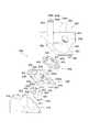
図3は、上述したホッパ装置600の詳細を説明するための斜視図である。同図に示すように、ホッパ装置600は、上述したガイドレール16上に支持固定されるフレーム体610と、ホッパモータ620と、回転ディスク載置プレート630と、回転ディスク640と、メダルタンク650とを有している。 FIG. 3 is a perspective view for explaining details of the
フレーム体610には、ホッパモータ620、回転ディスク載置プレート630、回転ディスク640等を収容する収容部611と、回転ディスク載置プレート630の後述する係合片631を係合する4個の係合片612とが設けられている。ここで、フレーム体610の収容部611は、回転ディスク載置プレート630、回転ディスク640等を収容する際、これらの回転ディスク載置プレート630や回転ディスク640等が上述したホッパ装置600から溢れたメダルを収納する図示しない補助貯留部側に向けて傾けられるようになっている。 In the
ホッパモータ620には、ねじ挿通穴を有する4個の取付部622が回転ディスク載置プレート630側に向けて突設されたプレート621が設けられている。このプレート621の下面側には、モータ本体623が取り付けられている。また、プレート621の上面側には、先端にねじ穴624aを有するモータ軸624が回転ディスク載置プレート630側に向けて突き出るように設けられている。なお、モータ本体623とモータ軸624との間には、ギヤ等が介在されており、モータ本体623からの駆動力がそのギヤ等を介してモータ軸624に伝達されるようになっている。また、プレート621の取付部622のねじ挿通穴に挿通される図示しないねじが回転ディスク載置プレート630側に螺着されることで、ホッパモータ620が回転ディスク載置プレート630の下面側に取り付けられるようになっている。 The
回転ディスク載置プレート630の外周には、上述したフレーム体610の係合片612に係合される4個の係合片612がフレーム体610側に向けて設けられている。回転ディスク載置プレート630の上面には、回転ディスク640を収容する円形の収容部632が設けられている。また、その収容部632の中心部分には、上述したホッパモータ620のモータ軸624が挿通される挿通穴632aが設けられている。 Four engaging
なお、その挿通穴632aから突出したホッパモータ620のモータ軸624には、ねじ挿通穴633aを有するとともに、コイルバネ634が介装され、回転ディスク640を支持して回転ディスク640を回転させる回転支持体633が取り付けられるようになっている。また、回転ディスク載置プレート630には、搬送ガイド部材658,659に連通する一対のメダル排出スリット636が設けられている。なお、図3では、搬送ガイド部材658に対応するメダル排出スリット636のみを示しているが、そのメダル排出スリット636と対向する側にもメダル排出スリット636と同様に搬送ガイド部材659に対応するメダル排出スリット(図示せず)が設けられている。 The
また、これらのメダル排出スリット636の近傍には、付勢手段637が設けられており、この付勢手段637によって下記のようにメダルの放出が行われるようになっている。 Further, an urging means 637 is provided in the vicinity of these medal discharge slits 636, and the medals are discharged by the urging means 637 as described below.
また、これらのメダル排出スリット636は、回転ディスク640の後述の8個のメダル穴642のうちの1個のメダル穴642に位置合わせされており、回転ディスク640の回転に合わせ、その回転ディスク640の後述のメダル穴642が上述した付勢手段637の位置に到達するすると、この付勢手段637により放出されるようになっている。なお、回転ディスク640は、上述したように、主制御基板300からのメダルの払い出しを行わせるべき旨の指令を受けるとったとき、たとえば正回転する。このとき、後述の8個のメダル穴642のうちの1個のメダル穴642からのメダルが搬送ガイド部材658に対応するメダル排出スリット636から放出されると、その搬送ガイド部材658により前扉3のメダル排出スリット18a側に搬送されて払い出される。 These medal discharge slits 636 are aligned with one
一方、主制御基板300からメダルの払い出しを行わせるべき旨の指令が出ていないにも関わらず、たとえばメダル管理の際に操作される強制メダル払出の操作や、たとえばホッパモータ620の所定の配線をショートさせるなどの不正行為があるとき、後述の駆動電力検知制御回路431により、ホッパモータ620の逆駆動により回転ディスク640が逆回転する。このとき、後述の8個のメダル穴642のうちの1個のメダル穴642が上述した付勢手段637の位置に到達するすると、この付勢手段637により搬送ガイド部材659に放出され、その搬送ガイド部材659により筐体2の背面側に設けられているメダル排出スリット18b側に搬送される。 On the other hand, although the
このように、たとえばホッパモータ620が強制的に駆動されてメダルが不正に抜き取られようとしても、メダルが上部受皿ユニット17側に排出されないため、ホッパモータ620を強制的に駆動させることによる不正行為が防止される。 In this way, for example, even if the
すなわち、たとえばメダル管理の際に操作される強制メダル払出の操作や、たとえばホッパモータ620の所定の配線をショートさせるなどの不正行為ににより、ホッパモータ620が強制的に駆動されるとき、ホッパモータ620を逆駆動させて回転ディスク640を逆回転させる制御は、後述の駆動電力検知制御回路431によって行われる。この場合、後述の駆動電力検知制御回路431は、ホッパモータ620が強制的に駆動される際のたとえば駆動電流電圧を検出したとき、後述の電源装置基板430からホッパ装置600に供給される駆動電源の極性を反転させるような制御を行う。 In other words, when the
また、回転ディスク載置プレート630の四隅には、メダルタンク650の後述の係合片652を係合する係合凹部635が設けられている。回転ディスク640の中心部には、上述したホッパモータ620のモータ軸624のねじ穴624aに螺着されるねじによって取り付けられる取付部641が設けられている。 Engagement recesses 635 for engaging engagement pieces 652 (to be described later) of the
また、回転ディスク640には、円周方向に一定間隔をもって形成された8個のメダル穴642が設けられている。これらのメダル穴642は、メダルの形状に合わせてほぼ円形に形成されているとともに、表面から裏面まで貫通するように形成されている。すなわち、回転ディスク640が正回転又は逆回転すると、メダルタンク650内のメダルが回転ディスク640の各メダル穴642に1枚ずつ収容され、メダルを収容したメダル穴642が上述したメダル排出スリット636の付勢手段637の位置に到達すると、この付勢手段637により搬送ガイド部材658又は659側に放出されるようになっている。 The
メダルタンク650には、上述した回転ディスク載置プレート630の係合凹部635に係合される係合片652を下面側に有したプレート651が設けられている。プレート651の上面側には、回転ディスク640等を収容する収容部653と、メダルタンク650から溢れたメダルを図示しない補助貯留部側に排出するオーバーフロー口654を有したメダルタンク体655とが設けられている。 The
ここで、搬送ガイド部材658は、主制御基板300からの払い出しの指令を受けてホッパ装置600の回転ディスク640がホッパモータ620の駆動によりたとえば正回転するとき、その回転ディスク640の正回転に合わせて回転ディスク640のメダル排出スリット636から受け渡されたメダルを上述したメダル排出スリット18a側に搬送するものである。搬送ガイド部材658のメダルの搬送構造としては、たとえば受け渡されたメダルを保持する穴や係合部等の保持部を有したベルト等が搬送ガイド部材658内部を上下方向に周回するような構造とすることができる。 Here, when the
このような構造とすることで、主制御基板300からの払い出しの指令を受けたとき、回転ディスク640がたとえば正回転し、これに合わせて搬送ガイド部材658により回転ディスク640のメダル排出スリット636から受け渡されたメダルがメダル排出スリット18a側に搬送されることにより、所定の枚数のメダルの払い出しが行われる。 With such a structure, when receiving a payout command from the
また、搬送ガイド部材658の開口部658bのメダル検出センサ658aにより、その払い出されたメダルの枚数が検出されると、電源装置基板430によるホッパ装置600のホッパモータ620の駆動が停止される。 When the
なお、搬送ガイド部材658は、メダルタンク650から垂直方向に延びているため、上述した上部受皿ユニット17にメダルを排出するメダル排出スリット18aに対して鋭角状に交わることになり、上述したように、そのメダル排出スリット18aからセルや針金等の不正行為治具が差し込まれようとしても、そのセルや針金等の不正行為治具が搬送ガイド部材658の開口部658b付近で折り曲がるばかりか、搬送ガイド部材658内部への侵入が困難となることから、セルや針金等の不正行為治具を用いての不正行為を防止することができる。 Since the
一方、搬送ガイド部材659は、主制御基板300からの払い出しの指令を受けていないとき、後述の駆動電力検知制御回路431によってホッパモータ620が強制的に駆動される際のたとえば駆動電流電圧が検知されると、その駆動電力検知制御回路431によってホッパモータ620が逆駆動され、回転ディスク640が逆回転することに合わせ、メダルを筐体2の背面側に設けられているメダル排出スリット18b側に搬送するものである。搬送ガイド部材659のメダルの搬送構造としては、搬送ガイド部材658と同様に、たとえば受け渡されたメダルを保持する穴や係合部等の保持部を有したベルト等が搬送ガイド部材659内部を上下方向に周回するような構造とすることができる。 On the other hand, the
このような構造とすることで、主制御基板300からの払い出しの指令を受けていないとき、ホッパモータ620が強制的に駆動されるような不正行為があると、回転ディスク640がたとえば逆回転し、これに合わせて搬送ガイド部材659により回転ディスク640の図示しないメダル排出スリットから受け渡されたメダルが筐体2の背面側に設けられているメダル排出スリット18b側に搬送される。 With such a structure, when there is an illegal act such that the
このような回転ディスク640の逆回転によりメダルが筐体2の背面側に設けられているメダル排出スリット18b側に搬送されるようにすることで、たとえば筐体2の隙間からたとえばセルや針金等の道具が差し込まれ、たとえばホッパ装置600のホッパモータ620の所定の配線がショートされ、メダルを不正に抜き取ろうとしてしてもメダルが上部受皿ユニット17側に排出されないため、ホッパモータ620を強制的に駆動させることによる不正行為が防止される。 By rotating the
また、搬送ガイド部材659の開口部659bのメダル検出センサ659aにより、搬送ガイド部材659によって搬送されたメダルが検出され、その検出されたメダルが所定の枚数に達すると、電源装置基板430によるホッパ装置600の後述のホッパモータ620の駆動が停止される。これにより、ホッパモータ620の所定の配線がショートされ続けていても、ホッパモータ620の駆動が停止されることで、たとえばホッパモータ620の故障等を防げる。 The
また、筐体2の背面側に設けられているメダル排出スリット18bは、垂直方向に延びた搬送ガイド部材659に対して鋭角状に交わっているため、たとえばそのメダル排出スリット18bからセルや針金等の不正行為治具が差し込まれようとしても、そのセルや針金等の不正行為治具が搬送ガイド部材659の開口部659b付近で折り曲がるばかりか、搬送ガイド部材659内部への侵入が困難となることから、セルや針金等の不正行為治具を用いての不正行為を防止することができる。 Further, since the medal discharge slit 18b provided on the back side of the housing 2 intersects the
また、メダル検出センサ659aにより、搬送ガイド部材659によって搬送されたメダルが検出された場合は、後述の駆動電力検知制御回路431とともに、後述のホッパモータ620が強制的に駆動されることによる不正行為があったことを検知することができる。 Further, when the medal detected by the
この場合、主制御基板300がメダル検出センサ659aによる検出結果、又は駆動電力検知制御回路431によるホッパモータ620の強制駆動の検知結果を受けて、サブ制御基板400に不正行為に対するエラー処理を指示する信号が出力される。これにより、サブ制御基板400により、たとえば上述した表示部101にエラー発生を示す内容がたとえばエラーコードとともに表示されたり、演出用ランプ104〜108によるエラーを示す点滅又は点灯が行われたり、放音部109,110からのエラーを示すエラー音の出力が行われたりする。 In this case, the
なお、この場合には、表示部101に表示されるエラーコードによってメダルの不正な抜き取りがあったことを確認できるが、演出用ランプ104〜108によるエラーを示す点滅又は点灯を通常のエラー処理とは異なるように行わせたり、放音部109,110からのエラーを示すエラー音の出力を通常のエラー処理とは異なるように行わせたりすることで、メダルの不正な抜き取りがあったことを直ちに確認することができる。 In this case, the error code displayed on the
このようなホッパ装置600では、上述した前扉3の操作卓部3Cのメダル投入部6から投入されたメダルがセレクト機構500で振り分けられた後、ガイド部材501によってメダルタンク体655内に収容される。 In such a
そして、ゲームの進行に応じて、電源装置基板430が主制御基板300からのメダルの払い出しを行わせるべき旨の指令を受けると、ホッパモータ620を駆動させて回転ディスク640を回転(この場合、正回転)させる。このとき、回転ディスク640の回転により、メダルタンク650内のメダルが回転ディスク640の各メダル穴642に1枚ずつ収容され、メダルを収容したメダル穴642が上述したメダル排出スリット636の付勢手段637の位置に到達すると、この付勢手段637により搬送ガイド部材658側に放出される。 Then, when the power
このとき、搬送ガイド部材658により、メダルがメダル排出スリット18a側に搬送されると、上部受皿ユニット17に排出される。また、搬送ガイド部材658の開口部658bのメダル検出センサ658aにより、その払い出されたメダルが検出され、所定の枚数のメダルの払い出しが検出されると、電源装置基板430によるホッパ装置600の後述のホッパモータ620の駆動が停止される。 At this time, when the medal is conveyed to the medal discharge slit 18 a side by the
また、そのメダル検出センサ658aによって所定枚数に到達したことが検出されると、電源装置基板430から主制御基板300に対して払い出し完了を示す信号が送出される。 When the
なお、そのメダル検出センサ658aによって、メダルが回転ディスク640のメダル穴642等に詰まるなどして、回転ディスク640の回転がぎこちなかったり、メダルの払い出しが所定枚数に到達しないことなどが所定時間続くと、電源装置基板430によるホッパモータ620の駆動が停止されるとともに、電源装置基板430から主制御基板300にエラーが発生したことを示す信号が送出される。 The
この場合、主制御基板300による通常のエラー処理が実行される。このエラー処理では、たとえば主制御基板300からサブ制御基板400にエラー処理を指示する信号が出力される。このとき、サブ制御基板400により、たとえば上述した表示部101にエラー発生を示す内容がたとえばエラーコードとともに表示されたり、演出用ランプ104〜108によるエラーを示す点滅又は点灯が行われたり、放音部109,110からのエラーを示すエラー音の出力が行われたりする。 In this case, normal error processing by the
以上のようにして、通常のメダルの払い出しと、メダルの払い出し等が旨く行かなかったときの通常のエラー処理とが行われる。 As described above, the normal medal payout and the normal error processing when the medal payout is not successful are performed.
図4は、スロットマシン1に設けられている制御システムを説明するためのブロック図である。制御システムは、主として主制御基板300、サブ制御基板400、回胴装置基板420、中央表示制御基板410、電源装置基板430、外部集中端子基板440を備え、それぞれが配線ケーブルによって接続されている。 FIG. 4 is a block diagram for explaining a control system provided in the slot machine 1. The control system mainly includes a
主制御基板300は、CPU(Central Processing Unit)301、半導体メモリであるROM(Read Only Memory)302、RAM(Random Access Memory)303等を備えている。 The
主制御基板300のCPU301は、ROM302に予め記憶されているシステムプログラムやスロットマシンゲーム用のプログラム等を読み込み、ゲームの進行に合わせて、サブ制御基板400、回胴装置基板420、中央表示制御基板410、電源装置基板430等に対する分散制御を行う。 The
ここで、CPU301による主な制御としては、メダルの投入(又はベットボタン7によるベット)とスタートレバー8の操作を条件として抽選を行い、その抽選結果が当選であり、かつ予め設定された有効ライン上にストップボタン9a,9b,9cの操作でその当選した図柄が停止したことを条件として所定枚数のメダルが払い出されるように、電源装置基板430を介してホッパ装置600を制御することである。 Here, as the main control by the
このとき、電源装置基板430からホッパ装置600のホッパモータ620に電源装置530からの駆動電源が与えられ、回転ディスク640の回転により所定枚数のメダルが払い出される。また、ホッパ装置600側に設けられているメダル検出センサ658aによって払い出されたメダルの枚数が所定枚数に到達したことが検出されると、ホッパモータ620駆動が停止されるとともに、電源装置基板430から主制御基板300に対して払い出し完了を示す信号が送出される。これにより、主制御基板300のCPU301は、メダルの払い出しが正常に行われたことを認識し、次のゲームの進行に合わせた制御に移ることができる。 At this time, driving power from the
また、CPU301による主な制御としては、ゲームの進行に合わせ、内部抽選した役の情報をサブ制御基板400へ供給し、その役に相当する演出を、上述した演出用ランプ104〜108、サイドランプ5a,5b、スピーカ13a,14a,109a,110a、表示部101を介して行わせることである。 In addition, as the main control by the
また、CPU301による主な制御としては、電源装置基板430に対し、所定枚数のメダルが払い出されるように指示を出してから、所定時間経過しても電源装置基板430からのメダルの払い出し完了を示す信号を受け取ることができなかった場合等において、通常のエラー処理を実行することである。すなわち、ホッパ装置600側において、メダルが回転ディスク640のメダル穴642等に詰まるなどして、回転ディスク640の回転がぎこちなかったり、ホッパ装置600側のメダル検出センサ658aによるメダルの払出枚数の検知が所定枚数に到達しないことなどが所定時間続くと、電源装置基板430によるホッパモータ620の駆動が停止されるとともに、電源装置基板430から主制御基板300にエラーが発生したことを示す信号が送出される。 The main control by the
この場合には、主制御基板300のCPU301からサブ制御基板400に通常のエラー処理を指示する信号が出力され、サブ制御基板400により、たとえば上述した表示部101にエラー発生を示す内容がたとえばエラーコードとともに表示されたり、演出用ランプ104〜108によるエラーを示す点滅又は点灯が行われたり、放音部109,110からのエラーを示すエラー音の出力が行われたりする。 In this case, the
また、CPU301による主な制御としては、電源装置基板430に対し、所定枚数のメダルが払い出されるように指示を出していないにも関わらず、後述の駆動電力検知制御回路431によってホッパモータ620における駆動電流電圧が検知されるか、又はメダル検出センサ659aによってメダルが検出されると、不正行為に対するエラー処理を実行することである。 In addition, as the main control by the
すなわち、たとえばホッパモータ620の所定の配線がショートされ、ホッパモータ620が強制的に駆動されたとき、後述の駆動電力検知制御回路431によりホッパモータ620への駆動電流電圧が検知される。このとき、後述の駆動電力検知制御回路431によってホッパモータ620が逆駆動され、回転ディスク640が逆回転し、メダルが搬送ガイド部材659により筐体2の背面側に設けられているメダル排出スリット18b側に搬送される。その際、搬送ガイド部材659に設けられているメダル検出センサ659aによりメダル排出スリット18b側に搬送されたメダルが検出される。なお、ホッパモータ620が逆駆動して回転ディスク640が逆回転する動作は、たとえばメダル管理の際に操作される強制メダル払出の操作によっても行われる。また、ホッパモータ620が逆駆動して回転ディスク640が逆回転した場合でも、主制御基板300による統括制御は継続して行われるようになっている。 That is, for example, when a predetermined wiring of the
このようなホッパ装置600側のホッパモータ620における駆動電流電圧の検知、あるいはメダル検出センサ659aによるメダルの検出は、たとえばメダルが不正に抜き取られる際に行われるものであるため、この場合には主制御基板300のCPU301からサブ制御基板400に不正行為に対するエラー処理を指示する信号が出力される。これにより、サブ制御基板400により、たとえば上述した表示部101にエラー発生を示す内容がたとえばエラーコードとともに表示されたり、演出用ランプ104〜108によるエラーを示す点滅又は点灯が行われたり、放音部109,110からのエラーを示すエラー音の出力が行われたりする。ただし、たとえばメダル管理の際に操作される強制メダル払出の操作があった場合は、主制御基板300によるエラー処理は行われない。 Such detection of the drive current voltage in the
なお、この場合には、表示部101に表示されるエラーコードによってメダルの不正な抜き取りがあったことを確認できるが、演出用ランプ104〜108によるエラーを示す点滅又は点灯を通常のエラー処理とは異なるように行わせたり、放音部109,110からのエラーを示すエラー音の出力を通常のエラー処理とは異なるように行わせたりすることで、メダルの不正な抜き取りがあったことを直ちに確認することができる。 In this case, the error code displayed on the
サブ制御基板400には、演出用ランプ104〜108と、サイドランプ5a,5bと、スピーカ13a,14a,109a,110aと、表示部101とが接続されている。そして、サブ制御基板400は、主制御基板300のCPU301からのゲームの進行に合わせた制御に基づき、上述した演出用ランプ104〜108を点滅又は点灯させたり、サイドランプ5a,5bを点滅又は点灯させたり、スピーカ13a,14a,109a,110aから効果音等を発生させたり、表示部101での所定の演出映像等の表示を行わせたりする。これにより、遊技者の視覚と聴覚に訴える演出を行うことができる。 The
回胴装置基板420には、上述したメインリール521,522,523を回転駆動するステッピングモータ521b,522b,523bと、メインリール521,522,523の各回転位置を検出する、たとえばフォトセンサ521a,522a,523aとが接続されている。 On the
そして、回胴装置基板420は、フォトセンサ521a,522a,523aからの検出信号と、ステッピングモータ521b,522b,523bへ出力した駆動パルス信号のパルス数との情報に基づいて、メインリール521,522,523の回転と制動、及び停止の制御を適切に行うようになっている。 The
また、回胴装置基板420は、上述したスタートレバー8、ストップボタン9a,9b,9c等の操作に伴って、主制御基板300からメインリール521,522,523のそれぞれの回転又は停止させるべき旨の制御信号が供給されると、フォトセンサ521a,522a,523aからの検出信号を取り込みながら、各メインリール521,522,523の回転位置を適切に把握しつつ、ステッピングモータ521b,522b,523bへの駆動パルス信号を制御して各メインリール521,522,523の回転動作を制御する。 Further, the
中央表示制御基板410には、上述したベットボタン7、スタートレバー8及びストップボタン9a,9b,9cが接続されている。中央表示制御基板410は、これらベットボタン7、スタートレバー8及びストップボタン9a,9b,9cからの出力信号を主制御基板300へ転送する中継基板として機能する。また、中央表示制御基板410は、セレクト機構500に設けられている図示しない遊技メダル検出センサからの出力信号を主制御基板300へ転送し、上述のメダル投入部6に投入されたメダル枚数を知らせるとともに、異物の投入や目詰まりの発生等を知らせる。 The central
そして、主制御基板300は、ベットボタン7又はセレクト機構500のメダルセンサが動作し、当該ゲームへの賭け枚数を検知し、スタートレバー8がオン操作されると、リール回転開始の指示がなされたことを検知する。さらに、ストップボタン9a,9b,9cが任意の順番でストップ操作されると、その順番でメインリール521,522,523を停止させるべき指示がなされたことを検知する。 Then, the
電源装置基板430には、ホッパ装置600と、駆動電力検知制御回路431と、電源装置530とが接続されている。電源装置基板430は、電源装置530で発生される各種電源電圧をホッパ装置600等の各所に配電する配電回路が形成されており、かかる配電回路からスロットマシン1の動作に必要なシステム電源を供給する。また、電源装置基板430は、主制御基板300からメダルの払い出しをすべき旨の指令を受けると、ホッパ装置600を制御してメダルの払い出しを行わせる。 A
ここで、駆動電力検知制御回路431は、ホッパモータ620の停止時において、たとえばホッパモータ620の所定の配線がショートされ、ホッパモータ620が強制的に駆動されたとき、ホッパモータ620への駆動電流電圧を検知する。また、駆動電力検知制御回路431は、ホッパモータ620への駆動電流電圧を検知すると、上述したように、ホッパモータ620を逆駆動させ、回転ディスク640を逆回転させる。 Here, the drive power
この場合、電源装置基板430は、主制御基板300から所定枚数のメダルの払い出しの指示を受けていないとき、駆動電力検知制御回路431によってホッパ装置600側のホッパモータ620への駆動電流電圧が検知されるか、あるいは上述したメダル検出センサ659aによってメダルが検出されると、主制御基板300へメダルが不正に抜き取られたことを示すエラー信号を出力する。 In this case, when the power
なお、たとえばメダル管理の際に操作される強制メダル払出の操作があるときは、主制御基板300へのエラー信号は出力されない。ここでは駆動電力検知制御回路431が電源装置基板430に接続されている場合で示しているが、その駆動電力検知制御回路431は電源装置基板430に組み込んでいてもよいし、ホッパ装置600側に組み込んでいてもよいし、主制御基板300側に組み込んでいてもよい。 For example, when there is a forced medal payout operation operated during medal management, an error signal is not output to the
外部集中端子基板440は、主制御基板300から出力されるスロットマシン1の状態信号又はゲームの進行状況等を示す信号を、図示しないホールコンピュータへ送出するための端子基板である。 The external concentrated
次に、スロットマシン1のメダル不正払出処理方法について説明する。なお、以下では、主制御基板300から電源装置基板430に所定枚数のメダルの払い出しの指示が出されることにより、ホッパ装置600が駆動されて所定枚数のメダルの払い出しが行われる場合を中心にして説明する。 Next, an illegal medal payout processing method for the slot machine 1 will be described. In the following, focusing on the case where the
まず、図5に示すように、主制御基板300のCPU301により、メダルの投入(又はベットボタン7によるベット)とスタートレバー8の操作を条件とした抽選が行われ、その抽選結果が当選であり、かつ予め設定された有効ライン上にストップボタン9a,9b,9cの操作でその当選した図柄が停止したことを条件として所定枚数のメダルが払い出されるように、電源装置基板430が制御される(ステップS1:yes)。 First, as shown in FIG. 5, the
このとき、電源装置基板430からホッパ装置600のホッパモータ620に電源装置530からの駆動電力が供給され(ステップS2)、ホッパモータ620の駆動により回転ディスク640が回転(この場合、正回転)する。ここで、回転ディスク640の回転により、メダルタンク650内のメダルが回転ディスク640の各メダル穴642に1枚ずつ収容され、メダルを収容したメダル穴642がメダル排出スリット636の上述した付勢手段637の位置に到達するすると、この付勢手段637により搬送ガイド部材658に放出され、その搬送ガイド部材658により前扉3のメダル排出スリット18a側に搬送されて払い出される。 At this time, drive power from the
このとき、搬送ガイド部材658の開口部658bに設けられているメダル検出センサ658aにより、メダル排出スリット18a側へのメダルの枚数である払い出し枚数が検出され、所定枚数に到達したことが検出されると(ステップS3)、電源装置基板430によるホッパモータ620の駆動が停止される(ステップS4)。 At this time, the
また、そのメダル検出センサ658aによって所定枚数に到達したことが検出されると、電源装置基板430から主制御基板300に対して払い出し完了を示す信号が送出される(ステップS5)。 When the
主制御基板300のCPU301がその払い出し完了を示す信号を受け取ると、次のメダルの投入(又はベットボタン7によるベット)とスタートレバー8の操作を条件とした抽選を行い、当選し、かつ予め設定された有効ライン上にストップボタン9a,9b,9cの操作でその当選した図柄が停止すると、上記同様に、電源装置基板430を制御することで、ホッパ装置600からの所定枚数のメダルの払い出しが行われる。 When the
ここで、ホッパ装置600でのメダルの払い出しにおいて、メダルが回転ディスク640のメダル穴642等に詰まるなどして、回転ディスク640の回転がぎこちなかったり、メダルの払い出しが所定枚数に到達しないことなどが所定時間続くと、電源装置基板430によるホッパモータ620の駆動が停止されるとともに、電源装置基板430から主制御基板300に通常のエラーが発生したことを示す信号が送出される(ステップS6)。 Here, in the payout of medals by the
この場合、主制御基板300による通常のエラー処理が実行される(ステップS7)。このエラー処理では、たとえば主制御基板300からサブ制御基板400にエラー処理を指示する信号が出力される。このとき、サブ制御基板400により、たとえば上述した表示部101にエラー発生を示す内容がたとえばエラーコードとともに表示されたり、演出用ランプ104〜108によるエラーを示す点滅又は点灯が行われたり、放音部109,110からのエラーを示すエラー音の出力が行われたりする。 In this case, normal error processing by the
このようなメダルの詰まりなどによるエラーが発生した場合は、前扉3を開放して図2で説明したように、ホッパ装置600を筐体2の底部2bに取り付けられるガイドレール16に沿って手前側に引き出すことで、メダルの詰まりなどを確認することができる。ここで、メダルの詰まりなどを解消した後、たとえば電源装置530に設けられているリセットボタンを操作することで、リセット処理が完了し(ステップS8)、通常のゲームの進行に移ることができる。 When such an error due to clogging of medals occurs, the
これに対し、通常のゲームの進行中に、主制御基板300のCPU301により、メダルの投入(又はベットボタン7によるベット)とスタートレバー8の操作を条件とした抽選が繰り返され、その抽選結果が当選でなかったり、その抽選結果が当選であっても予め設定された有効ライン上にストップボタン9a,9b,9cの操作でその当選した図柄が停止しなければメダルの払い出しが指示されないことになる(ステップS1:no)。 On the other hand, during the normal game, the
ここで、主制御基板300のCPU301から電源装置基板430側に所定枚数のメダルの払い出しの指示が出されていないとき、駆動電力検知制御回路431によってホッパ装置600側のホッパモータ620の不正駆動、すなわちホッパモータ620における駆動電流電圧が検知されると(ステップS9:yes)、駆動電力検知制御回路431によりホッパモータ620が逆駆動され、回転ディスク640が逆回転する(ステップS10)。このとき、回転ディスク640のメダル穴642からのメダルが図示しないメダル排出スリットの上述した付勢手段637の位置に到達するすると、この付勢手段637により搬送ガイド部材659に放出され、その搬送ガイド部材659により筐体2の背面側に設けられているメダル排出スリット18b側に搬送される。 Here, when the instruction for paying out a predetermined number of medals is not issued from the
このように、ホッパモータ620が強制的に駆動されてメダルが不正に抜き取られようとしても、メダルが上部受皿ユニット17側に排出されないため、ホッパモータ620を強制的に駆動させることによる不正行為が防止される。このとき、搬送ガイド部材659の開口部659bのメダル検出センサ659aにより、搬送ガイド部材659によって搬送されたメダルが検出され、その検出されたメダルが所定の枚数に達すると、電源装置基板430によるホッパ装置600の後述のホッパモータ620の駆動が停止される。ただし、上述したように、たとえばメダル管理の際に操作される強制メダル払出の操作がある場合も、上記同様に、回転ディスク640が逆回転してメダルが筐体2の背面側に設けられているメダル排出スリット18b側に搬送される。 In this way, even if the
また、メダル検出センサ659aにより、搬送ガイド部材659によって搬送されたメダルが検出された場合は、駆動電力検知制御回路431とともに、ホッパモータ620が強制的に駆動されることによるたとえば不正行為があったことを検知することができる。 Further, when a medal conveyed by the
このようなホッパ装置600側のホッパモータ620における駆動電力検知制御回路431によっての駆動電流電圧の検知、あるいはメダル検出センサ659aによるメダルの検出は、たとえばメダルが不正に抜き取られる際に行われるものであるため、電源装置基板430から主制御基板300へメダルが不正に抜き取られたことを示すエラー信号が出力される。ただし、上述したように、たとえばメダル管理の際に操作される強制メダル払出の操作がある場合は、エラー信号の出力は行われない。 The detection of the driving current voltage by the driving power
主制御基板300のCPU301がこのようなメダルが不正に抜き取られたことを示すエラー信号を受け取ると、不正行為に対するエラー処理を実行する(ステップS11)。この場合、上述した通常のエラー処理と同様に、サブ制御基板400により、たとえば上述した表示部101にエラー発生を示す内容がたとえばエラーコードとともに表示されたり、演出用ランプ104〜108によるエラーを示す点滅又は点灯が行われたり、放音部109,110からのエラーを示すエラー音の出力が行われたりするようにしてもよい。ただし、この場合には、たとえば表示部101にメダルが不正に抜き取られたことを示すエラーコードが表示されるようにすれば、ホールスタッフ等がそのエラーコードからメダルが不正に抜き取られたことを即座に判断することができる。 When the
なお、この場合には、表示部101に表示されるエラーコードによってメダルの不正な抜き取りがあったことを確認できるが、演出用ランプ104〜108によるエラーを示す点滅又は点灯を通常のエラー処理とは異なるように行わせたり、放音部109,110からのエラーを示すエラー音の出力を通常のエラー処理とは異なるように行わせたりすることで、メダルの不正な抜き取りがあったことを直ちに確認することができる。 In this case, the error code displayed on the
このように、本実施例では、通常のメダルの払い出し時に、メイン制御手段としてのたとえば主制御基板300からのメダルの払い出しの信号があると、電源供給制御手段としてのたとえば電源装置基板430からホッパ装置600のホッパモータ620へ駆動電源が供給され、このとき、検知制御手段としての駆動電力検知制御回路431により主制御基板300からのメダルの払い出しの信号が検知されると、駆動電力検知制御回路431によって回転ディスク640が一方向(たとえば正回転)に回転され、これに合わせて第1搬送ガイド手段としての搬送ガイド部材658により回転ディスク640からのメダルが前扉3に設けられている第1メダル排出口であるメダル排出口18aに搬送されるようにした。 As described above, in this embodiment, when a medal payout signal is received from, for example, the
一方、主制御基板300からのメダルの払い出しの信号がないときにホッパ装置600のホッパモータ620が駆動される場合は、駆動電力検知制御回路431により回転ディスク640が他方向(たとえば逆回転)に回転され、これに合わせて第2搬送ガイド手段としての搬送ガイド部材659により回転ディスク640からのメダルが筐体2のたとえば背面側に設けられている第2メダル排出口であるメダル排出口18bに搬送されるようにした。 On the other hand, when the
ここで、メダルの払い出しの信号がないときにホッパ装置600のホッパモータ620が駆動される場合として、上述したように、たとえばメダル管理の際に操作される強制メダル払出の操作や、たとえばホッパモータ620の所定の配線をショートさせるなどの不正行為によることがある。 Here, as a case where the
このような場合は、全て回転ディスク640が他方向(たとえば逆回転)に回転することで、メダルが筐体2のたとえば背面側に設けられているメダル排出口18bに搬送されることから、メダルが前扉3に設けられているメダル排出口18aから払い出されないようにすることができる。 In such a case, all the
これにより、たとえばホッパモータ620の所定の配線をショートさせるなどの不正行為がある場合は、前扉3に設けられているメダル排出口18aからの払い出しが行われないため、メダルの不正な抜き取りが防止される。 As a result, for example, when there is an illegal act such as short-circuiting a predetermined wiring of the
一方、たとえばメダル管理の際に操作される強制メダル払出の操作があったときも、メダルが筐体2のたとえば背面側に設けられているメダル排出口18bに搬送されることから、ホッパ装置600内のメダルをケース等に移し換えるような作業を行わなくてもよくなる。 On the other hand, for example, even when a forced medal payout operation is performed during medal management, the medal is transported to the
スロットマシンに限らず、パチンコ機、ピンボールゲーム機、アレンジボールゲーム機、じゃん球といった他の遊技機にも適用可能である。 Not only slot machines but also other game machines such as pachinko machines, pinball game machines, arrange ball game machines, and ball balls are applicable.
1 スロットマシン
2 筐体
3 前扉
5a,5b サイドランプ
6 メダル投入部
7 ベットボタン
8 スタートレバー
9a,9b,9c ストップボタン
11 下部受皿ユニット
12 メダル排出スリット
13,14 演出効果音部
13a,14a スピーカ
16 ガイドレール
17 上部受皿ユニット
18a,18b メダル排出スリット
100 演出表示部
101 表示部
102 表示パネル
104〜108 演出用ランプ
109,110 放音部
109a,110a スピーカ
200 メイン演出部
300 主制御基板
301 CPU
400 サブ制御基板
410 中央表示制御基板
420 回胴装置基板
430 電源装置基板
431 駆動電力検知回路
440 外部集中端子基板
500 セレクト機構
520 回胴装置
521,522,523 メインリール
530 電源装置
600 ホッパ装置
610 フレーム体
611 収容部
612 係合片
620 ホッパモータ
623 モータ本体
624 モータ軸
630 回転ディスク載置プレート
640 回転ディスク
642 メダル穴
650 メダルタンク
655 メダルタンク体
658,659 搬送ガイド部材
658a,659a メダル検出センサDESCRIPTION OF SYMBOLS 1 Slot machine 2
400
Claims (3)
Translated fromJapanese前記ホッパ装置のメダルの払い出しを行う回転ディスクを駆動するホッパモータに駆動電源を供給する電源供給制御手段と、
前記ホッパモータのメダルの払い出しの信号を検知すると、前記回転ディスクを一方向へ回転させ、前記ホッパモータのメダルの払い出しの信号を検知しないとき、前記回転ディスクを他方向への回転させる検知制御手段と、
前記回転ディスクの一方向への回転に合わせ、該回転ディスクからのメダルを前記前扉に設けられている第1メダル排出口に搬送する第1搬送ガイド手段と、
前記回転ディスクの他方向への回転に合わせ、該回転ディスクからのメダルを前記筐体の前記第1メダル排出口とは別な個所に設けられている第2メダル排出口に搬送する第2搬送ガイド手段と、
少なくともゲームの進行に合わせて前記メダルの払い出しの信号を出力するメイン制御手段とを備える
ことを特徴とするメダル不正払出処理システム。A medal illegal payout processing system that performs processing for an illegal medal payout from a hopper device arranged inside a housing of a gaming machine that is closed by a front door,
Power supply control means for supplying drive power to a hopper motor that drives a rotating disk for paying out medals of the hopper device;
A detection control means for rotating the rotating disk in one direction when detecting a signal for paying out a medal of the hopper motor, and for rotating the rotating disk in the other direction when detecting a signal for paying out a medal of the hopper motor;
First conveying guide means for conveying a medal from the rotating disk to a first medal discharge port provided in the front door in accordance with the rotation of the rotating disk in one direction;
Second transport for transporting medals from the rotating disk to a second medal discharge port provided at a location different from the first medal discharge port of the housing in accordance with the rotation of the rotating disk in the other direction. Guide means;
A medal illegal payout processing system comprising: main control means for outputting a signal for paying out the medal in accordance with the progress of the game.
前記ホッパ装置のメダルの払い出しを行う回転ディスクを駆動するホッパモータに駆動電源を供給する工程と、
前記ホッパモータのメダルの払い出しの信号を検知すると、前記回転ディスクを一方向へ回転させ、前記ホッパモータのメダルの払い出しの信号を検知しないとき、前記回転ディスクを他方向への回転させる工程と、
前記回転ディスクの一方向への回転に合わせ、該回転ディスクからのメダルを前記前扉に設けられている第1メダル排出口に搬送する工程と、
前記回転ディスクの他方向への回転に合わせ、該回転ディスクからのメダルを前記筐体の前記第1メダル排出口とは別な個所に設けられている第2メダル排出口に搬送する工程と、
少なくともゲームの進行に合わせて前記メダルの払い出しの信号を出力する工程とを有する
ことを特徴とするメダル不正払出処理方法。A medal illegal payout processing method for performing a process for illegal medal payout from a hopper device arranged inside a housing of a gaming machine closed by a front door,
Supplying drive power to a hopper motor that drives a rotating disk for paying out medals of the hopper device;
Rotating the rotating disk in one direction when detecting a signal for paying out a medal of the hopper motor, and rotating the rotating disk in another direction when not detecting a signal for paying out a medal of the hopper motor;
In accordance with the rotation of the rotating disk in one direction, a medal from the rotating disk is conveyed to a first medal outlet provided in the front door;
A step of conveying medals from the rotating disk to a second medal outlet provided at a location different from the first medal outlet of the housing in accordance with the rotation of the rotating disk in the other direction;
A medal payout processing method comprising: outputting a medal payout signal at least in accordance with the progress of the game.
Priority Applications (1)
| Application Number | Priority Date | Filing Date | Title |
|---|---|---|---|
| JP2007093296AJP2008246061A (en) | 2007-03-30 | 2007-03-30 | System for processing fraudulent putout of token, method for processing fraudulent putout of token and game machine |
Applications Claiming Priority (1)
| Application Number | Priority Date | Filing Date | Title |
|---|---|---|---|
| JP2007093296AJP2008246061A (en) | 2007-03-30 | 2007-03-30 | System for processing fraudulent putout of token, method for processing fraudulent putout of token and game machine |
Publications (1)
| Publication Number | Publication Date |
|---|---|
| JP2008246061Atrue JP2008246061A (en) | 2008-10-16 |
Family
ID=39971717
Family Applications (1)
| Application Number | Title | Priority Date | Filing Date |
|---|---|---|---|
| JP2007093296APendingJP2008246061A (en) | 2007-03-30 | 2007-03-30 | System for processing fraudulent putout of token, method for processing fraudulent putout of token and game machine |
Country Status (1)
| Country | Link |
|---|---|
| JP (1) | JP2008246061A (en) |
Cited By (41)
| Publication number | Priority date | Publication date | Assignee | Title |
|---|---|---|---|---|
| US8628086B2 (en) | 2004-09-14 | 2014-01-14 | Shfl Entertainment, Inc. | Shuffling devices including one or more sensors for detecting operational parameters and related methods |
| JP5688719B1 (en)* | 2013-10-08 | 2015-03-25 | 山佐株式会社 | Slot machine |
| US9220971B2 (en) | 2006-05-31 | 2015-12-29 | Bally Gaming, Inc. | Automatic system and methods for accurate card handling |
| US9220972B2 (en) | 2001-09-28 | 2015-12-29 | Bally Gaming, Inc. | Multiple mode card shuffler and card reading device |
| US9233298B2 (en) | 2009-04-07 | 2016-01-12 | Bally Gaming, Inc. | Playing card shuffler |
| US9259640B2 (en) | 2007-06-06 | 2016-02-16 | Bally Gaming, Inc. | Apparatus, system, method, and computer-readable medium for casino card handling with multiple hand recall feature |
| US9266012B2 (en) | 1998-04-15 | 2016-02-23 | Bally Gaming, Inc. | Methods of randomizing cards |
| US9266011B2 (en) | 1997-03-13 | 2016-02-23 | Bally Gaming, Inc. | Card-handling devices and methods of using such devices |
| US9320964B2 (en) | 2006-11-10 | 2016-04-26 | Bally Gaming, Inc. | System for billing usage of a card handling device |
| US9333415B2 (en) | 2002-02-08 | 2016-05-10 | Bally Gaming, Inc. | Methods for handling playing cards with a card handling device |
| US9345951B2 (en) | 2001-09-28 | 2016-05-24 | Bally Gaming, Inc. | Methods and apparatuses for an automatic card handling device and communication networks including same |
| US9345952B2 (en) | 2006-03-24 | 2016-05-24 | Shuffle Master Gmbh & Co Kg | Card handling apparatus |
| US9370710B2 (en) | 1998-04-15 | 2016-06-21 | Bally Gaming, Inc. | Methods for shuffling cards and rack assemblies for use in automatic card shufflers |
| US9378766B2 (en) | 2012-09-28 | 2016-06-28 | Bally Gaming, Inc. | Card recognition system, card handling device, and method for tuning a card handling device |
| US9387390B2 (en) | 2005-06-13 | 2016-07-12 | Bally Gaming, Inc. | Card shuffling apparatus and card handling device |
| USD764599S1 (en) | 2014-08-01 | 2016-08-23 | Bally Gaming, Inc. | Card shuffler device |
| US9452346B2 (en) | 2001-09-28 | 2016-09-27 | Bally Gaming, Inc. | Method and apparatus for using upstream communication in a card shuffler |
| US9474957B2 (en) | 2014-05-15 | 2016-10-25 | Bally Gaming, Inc. | Playing card handling devices, systems, and methods for verifying sets of cards |
| US9504905B2 (en) | 2014-09-19 | 2016-11-29 | Bally Gaming, Inc. | Card shuffling device and calibration method |
| US9511274B2 (en) | 2012-09-28 | 2016-12-06 | Bally Gaming Inc. | Methods for automatically generating a card deck library and master images for a deck of cards, and a related card processing apparatus |
| US9539494B2 (en) | 2009-04-07 | 2017-01-10 | Bally Gaming, Inc. | Card shuffling apparatuses and related methods |
| US9566501B2 (en) | 2014-08-01 | 2017-02-14 | Bally Gaming, Inc. | Hand-forming card shuffling apparatuses including multi-card storage compartments, and related methods |
| US9623317B2 (en) | 2006-07-05 | 2017-04-18 | Bally Gaming, Inc. | Method of readying a card shuffler |
| US9713761B2 (en) | 2011-07-29 | 2017-07-25 | Bally Gaming, Inc. | Method for shuffling and dealing cards |
| US9731190B2 (en) | 2011-07-29 | 2017-08-15 | Bally Gaming, Inc. | Method and apparatus for shuffling and handling cards |
| US9764221B2 (en) | 2006-05-31 | 2017-09-19 | Bally Gaming, Inc. | Card-feeding device for a card-handling device including a pivotable arm |
| US9802114B2 (en) | 2010-10-14 | 2017-10-31 | Shuffle Master Gmbh & Co Kg | Card handling systems, devices for use in card handling systems and related methods |
| US9849368B2 (en) | 2012-07-27 | 2017-12-26 | Bally Gaming, Inc. | Batch card shuffling apparatuses including multi card storage compartments |
| US9993719B2 (en) | 2015-12-04 | 2018-06-12 | Shuffle Master Gmbh & Co Kg | Card handling devices and related assemblies and components |
| US10022617B2 (en) | 2001-09-28 | 2018-07-17 | Bally Gaming, Inc. | Shuffler and method of shuffling cards |
| US10279245B2 (en) | 2014-04-11 | 2019-05-07 | Bally Gaming, Inc. | Method and apparatus for handling cards |
| US10339765B2 (en) | 2016-09-26 | 2019-07-02 | Shuffle Master Gmbh & Co Kg | Devices, systems, and related methods for real-time monitoring and display of related data for casino gaming devices |
| US10456659B2 (en) | 2000-04-12 | 2019-10-29 | Shuffle Master Gmbh & Co Kg | Card handling devices and systems |
| US10532272B2 (en) | 2001-09-28 | 2020-01-14 | Bally Gaming, Inc. | Flush mounted card shuffler that elevates cards |
| US10933300B2 (en) | 2016-09-26 | 2021-03-02 | Shuffle Master Gmbh & Co Kg | Card handling devices and related assemblies and components |
| US11173383B2 (en) | 2019-10-07 | 2021-11-16 | Sg Gaming, Inc. | Card-handling devices and related methods, assemblies, and components |
| US11338194B2 (en) | 2018-09-28 | 2022-05-24 | Sg Gaming, Inc. | Automatic card shufflers and related methods of automatic jam recovery |
| US11376489B2 (en) | 2018-09-14 | 2022-07-05 | Sg Gaming, Inc. | Card-handling devices and related methods, assemblies, and components |
| US11898837B2 (en) | 2019-09-10 | 2024-02-13 | Shuffle Master Gmbh & Co Kg | Card-handling devices with defect detection and related methods |
| US11896891B2 (en) | 2018-09-14 | 2024-02-13 | Sg Gaming, Inc. | Card-handling devices and related methods, assemblies, and components |
| US12290745B2 (en) | 2018-09-14 | 2025-05-06 | Sg Gaming, Inc. | Card-handling devices and related methods, assemblies, and components |
Citations (4)
| Publication number | Priority date | Publication date | Assignee | Title |
|---|---|---|---|---|
| JP2002222446A (en)* | 2001-01-25 | 2002-08-09 | Juki Corp | Coin ejection device |
| JP2004215952A (en)* | 2003-01-16 | 2004-08-05 | Yamasa Kk | Medal putting out apparatus, and slot machine using the same |
| JP2005034221A (en)* | 2003-07-16 | 2005-02-10 | Daiichi Shokai Co Ltd | Game machine |
| JP2005052430A (en)* | 2003-08-05 | 2005-03-03 | San Kiko Kk | System for detecting illegality in game hall |
- 2007
- 2007-03-30JPJP2007093296Apatent/JP2008246061A/enactivePending
Patent Citations (4)
| Publication number | Priority date | Publication date | Assignee | Title |
|---|---|---|---|---|
| JP2002222446A (en)* | 2001-01-25 | 2002-08-09 | Juki Corp | Coin ejection device |
| JP2004215952A (en)* | 2003-01-16 | 2004-08-05 | Yamasa Kk | Medal putting out apparatus, and slot machine using the same |
| JP2005034221A (en)* | 2003-07-16 | 2005-02-10 | Daiichi Shokai Co Ltd | Game machine |
| JP2005052430A (en)* | 2003-08-05 | 2005-03-03 | San Kiko Kk | System for detecting illegality in game hall |
Cited By (96)
| Publication number | Priority date | Publication date | Assignee | Title |
|---|---|---|---|---|
| US9266011B2 (en) | 1997-03-13 | 2016-02-23 | Bally Gaming, Inc. | Card-handling devices and methods of using such devices |
| US9266012B2 (en) | 1998-04-15 | 2016-02-23 | Bally Gaming, Inc. | Methods of randomizing cards |
| US9561426B2 (en) | 1998-04-15 | 2017-02-07 | Bally Gaming, Inc. | Card-handling devices |
| US9370710B2 (en) | 1998-04-15 | 2016-06-21 | Bally Gaming, Inc. | Methods for shuffling cards and rack assemblies for use in automatic card shufflers |
| US9861881B2 (en) | 1998-04-15 | 2018-01-09 | Bally Gaming, Inc. | Card handling apparatuses and methods for handling cards |
| US10456659B2 (en) | 2000-04-12 | 2019-10-29 | Shuffle Master Gmbh & Co Kg | Card handling devices and systems |
| US10022617B2 (en) | 2001-09-28 | 2018-07-17 | Bally Gaming, Inc. | Shuffler and method of shuffling cards |
| US10004976B2 (en) | 2001-09-28 | 2018-06-26 | Bally Gaming, Inc. | Card handling devices and related methods |
| US10226687B2 (en) | 2001-09-28 | 2019-03-12 | Bally Gaming, Inc. | Method and apparatus for using upstream communication in a card shuffler |
| US10549177B2 (en) | 2001-09-28 | 2020-02-04 | Bally Gaming, Inc. | Card handling devices comprising angled support surfaces |
| US9345951B2 (en) | 2001-09-28 | 2016-05-24 | Bally Gaming, Inc. | Methods and apparatuses for an automatic card handling device and communication networks including same |
| US9220972B2 (en) | 2001-09-28 | 2015-12-29 | Bally Gaming, Inc. | Multiple mode card shuffler and card reading device |
| US10343054B2 (en) | 2001-09-28 | 2019-07-09 | Bally Gaming, Inc. | Systems including automatic card handling apparatuses and related methods |
| US10086260B2 (en) | 2001-09-28 | 2018-10-02 | Bally Gaming, Inc. | Method and apparatus for using upstream communication in a card shuffler |
| US10532272B2 (en) | 2001-09-28 | 2020-01-14 | Bally Gaming, Inc. | Flush mounted card shuffler that elevates cards |
| US10569159B2 (en) | 2001-09-28 | 2020-02-25 | Bally Gaming, Inc. | Card shufflers and gaming tables having shufflers |
| US9452346B2 (en) | 2001-09-28 | 2016-09-27 | Bally Gaming, Inc. | Method and apparatus for using upstream communication in a card shuffler |
| US10092821B2 (en) | 2002-02-08 | 2018-10-09 | Bally Technology, Inc. | Card-handling device and method of operation |
| US9700785B2 (en) | 2002-02-08 | 2017-07-11 | Bally Gaming, Inc. | Card-handling device and method of operation |
| US9333415B2 (en) | 2002-02-08 | 2016-05-10 | Bally Gaming, Inc. | Methods for handling playing cards with a card handling device |
| US9616324B2 (en) | 2004-09-14 | 2017-04-11 | Bally Gaming, Inc. | Shuffling devices including one or more sensors for detecting operational parameters and related methods |
| US8628086B2 (en) | 2004-09-14 | 2014-01-14 | Shfl Entertainment, Inc. | Shuffling devices including one or more sensors for detecting operational parameters and related methods |
| US10576363B2 (en) | 2005-06-13 | 2020-03-03 | Bally Gaming, Inc. | Card shuffling apparatus and card handling device |
| US9387390B2 (en) | 2005-06-13 | 2016-07-12 | Bally Gaming, Inc. | Card shuffling apparatus and card handling device |
| US9908034B2 (en) | 2005-06-13 | 2018-03-06 | Bally Gaming, Inc. | Card shuffling apparatus and card handling device |
| US9345952B2 (en) | 2006-03-24 | 2016-05-24 | Shuffle Master Gmbh & Co Kg | Card handling apparatus |
| US10220297B2 (en) | 2006-03-24 | 2019-03-05 | Shuffle Master Gmbh & Co Kg | Card handling apparatus and associated methods |
| US9789385B2 (en) | 2006-03-24 | 2017-10-17 | Shuffle Master Gmbh & Co Kg | Card handling apparatus |
| US9901810B2 (en) | 2006-05-31 | 2018-02-27 | Bally Gaming, Inc. | Playing card shuffling devices and related methods |
| US10525329B2 (en) | 2006-05-31 | 2020-01-07 | Bally Gaming, Inc. | Methods of feeding cards |
| US9220971B2 (en) | 2006-05-31 | 2015-12-29 | Bally Gaming, Inc. | Automatic system and methods for accurate card handling |
| US10926164B2 (en) | 2006-05-31 | 2021-02-23 | Sg Gaming, Inc. | Playing card handling devices and related methods |
| US9764221B2 (en) | 2006-05-31 | 2017-09-19 | Bally Gaming, Inc. | Card-feeding device for a card-handling device including a pivotable arm |
| US10226686B2 (en) | 2006-07-05 | 2019-03-12 | Bally Gaming, Inc. | Automatic card shuffler with pivotal card weight and divider gate |
| US9623317B2 (en) | 2006-07-05 | 2017-04-18 | Bally Gaming, Inc. | Method of readying a card shuffler |
| US10639542B2 (en) | 2006-07-05 | 2020-05-05 | Sg Gaming, Inc. | Ergonomic card-shuffling devices |
| US10286291B2 (en) | 2006-11-10 | 2019-05-14 | Bally Gaming, Inc. | Remotely serviceable card-handling devices and related systems and methods |
| US9320964B2 (en) | 2006-11-10 | 2016-04-26 | Bally Gaming, Inc. | System for billing usage of a card handling device |
| US10410475B2 (en) | 2007-06-06 | 2019-09-10 | Bally Gaming, Inc. | Apparatus, system, method, and computer-readable medium for casino card handling with multiple hand recall feature |
| US9633523B2 (en) | 2007-06-06 | 2017-04-25 | Bally Gaming, Inc. | Apparatus, system, method, and computer-readable medium for casino card handling with multiple hand recall feature |
| US10504337B2 (en) | 2007-06-06 | 2019-12-10 | Bally Gaming, Inc. | Casino card handling system with game play feed |
| US9922502B2 (en) | 2007-06-06 | 2018-03-20 | Balley Gaming, Inc. | Apparatus, system, method, and computer-readable medium for casino card handling with multiple hand recall feature |
| US9259640B2 (en) | 2007-06-06 | 2016-02-16 | Bally Gaming, Inc. | Apparatus, system, method, and computer-readable medium for casino card handling with multiple hand recall feature |
| US10137359B2 (en) | 2009-04-07 | 2018-11-27 | Bally Gaming, Inc. | Playing card shufflers and related methods |
| US9233298B2 (en) | 2009-04-07 | 2016-01-12 | Bally Gaming, Inc. | Playing card shuffler |
| US10166461B2 (en) | 2009-04-07 | 2019-01-01 | Bally Gaming, Inc. | Card shuffling apparatuses and related methods |
| US9744436B2 (en) | 2009-04-07 | 2017-08-29 | Bally Gaming, Inc. | Playing card shuffler |
| US9539494B2 (en) | 2009-04-07 | 2017-01-10 | Bally Gaming, Inc. | Card shuffling apparatuses and related methods |
| US10814212B2 (en) | 2010-10-14 | 2020-10-27 | Shuffle Master Gmbh & Co Kg | Shoe devices and card handling systems |
| US10583349B2 (en) | 2010-10-14 | 2020-03-10 | Shuffle Master Gmbh & Co Kg | Card handling systems, devices for use in card handling systems and related methods |
| US10722779B2 (en) | 2010-10-14 | 2020-07-28 | Shuffle Master Gmbh & Co Kg | Methods of operating card handling devices of card handling systems |
| US9802114B2 (en) | 2010-10-14 | 2017-10-31 | Shuffle Master Gmbh & Co Kg | Card handling systems, devices for use in card handling systems and related methods |
| US12090388B2 (en) | 2010-11-10 | 2024-09-17 | LNW Gaming | Playing card handling devices |
| US10933301B2 (en) | 2011-07-29 | 2021-03-02 | Sg Gaming, Inc. | Method for shuffling and dealing cards |
| US9731190B2 (en) | 2011-07-29 | 2017-08-15 | Bally Gaming, Inc. | Method and apparatus for shuffling and handling cards |
| US9713761B2 (en) | 2011-07-29 | 2017-07-25 | Bally Gaming, Inc. | Method for shuffling and dealing cards |
| US10668362B2 (en) | 2011-07-29 | 2020-06-02 | Sg Gaming, Inc. | Method for shuffling and dealing cards |
| US9849368B2 (en) | 2012-07-27 | 2017-12-26 | Bally Gaming, Inc. | Batch card shuffling apparatuses including multi card storage compartments |
| US10668361B2 (en) | 2012-07-27 | 2020-06-02 | Sg Gaming, Inc. | Batch card shuffling apparatuses including multi-card storage compartments, and related methods |
| US10668364B2 (en) | 2012-07-27 | 2020-06-02 | Sg Gaming, Inc. | Automatic card shufflers and related methods |
| US9861880B2 (en) | 2012-07-27 | 2018-01-09 | Bally Gaming, Inc. | Card-handling methods with simultaneous removal |
| US10124241B2 (en) | 2012-07-27 | 2018-11-13 | Bally Gaming, Inc. | Batch card shuffling apparatuses including multi card storage compartments, and related methods |
| US10403324B2 (en) | 2012-09-28 | 2019-09-03 | Bally Gaming, Inc. | Card recognition system, card handling device, and method for tuning a card handling device |
| US9378766B2 (en) | 2012-09-28 | 2016-06-28 | Bally Gaming, Inc. | Card recognition system, card handling device, and method for tuning a card handling device |
| US9511274B2 (en) | 2012-09-28 | 2016-12-06 | Bally Gaming Inc. | Methods for automatically generating a card deck library and master images for a deck of cards, and a related card processing apparatus |
| US9679603B2 (en) | 2012-09-28 | 2017-06-13 | Bally Gaming, Inc. | Card recognition system, card handling device, and method for tuning a card handling device |
| US10398966B2 (en) | 2012-09-28 | 2019-09-03 | Bally Gaming, Inc. | Methods for automatically generating a card deck library and master images for a deck of cards, and a related card processing apparatus |
| JP5688719B1 (en)* | 2013-10-08 | 2015-03-25 | 山佐株式会社 | Slot machine |
| US10279245B2 (en) | 2014-04-11 | 2019-05-07 | Bally Gaming, Inc. | Method and apparatus for handling cards |
| US9474957B2 (en) | 2014-05-15 | 2016-10-25 | Bally Gaming, Inc. | Playing card handling devices, systems, and methods for verifying sets of cards |
| US10092819B2 (en) | 2014-05-15 | 2018-10-09 | Bally Gaming, Inc. | Playing card handling devices, systems, and methods for verifying sets of cards |
| US10238954B2 (en) | 2014-08-01 | 2019-03-26 | Bally Gaming, Inc. | Hand-forming card shuffling apparatuses including multi-card storage compartments, and related methods |
| USD764599S1 (en) | 2014-08-01 | 2016-08-23 | Bally Gaming, Inc. | Card shuffler device |
| US9566501B2 (en) | 2014-08-01 | 2017-02-14 | Bally Gaming, Inc. | Hand-forming card shuffling apparatuses including multi-card storage compartments, and related methods |
| US10864431B2 (en) | 2014-08-01 | 2020-12-15 | Sg Gaming, Inc. | Methods of making and using hand-forming card shufflers |
| US10486055B2 (en) | 2014-09-19 | 2019-11-26 | Bally Gaming, Inc. | Card handling devices and methods of randomizing playing cards |
| US10857448B2 (en) | 2014-09-19 | 2020-12-08 | Sg Gaming, Inc. | Card handling devices and associated methods |
| US11358051B2 (en) | 2014-09-19 | 2022-06-14 | Sg Gaming, Inc. | Card handling devices and associated methods |
| US12029969B2 (en) | 2014-09-19 | 2024-07-09 | Lnw Gaming, Inc. | Card handling devices and associated methods |
| US9504905B2 (en) | 2014-09-19 | 2016-11-29 | Bally Gaming, Inc. | Card shuffling device and calibration method |
| US9993719B2 (en) | 2015-12-04 | 2018-06-12 | Shuffle Master Gmbh & Co Kg | Card handling devices and related assemblies and components |
| US10668363B2 (en) | 2015-12-04 | 2020-06-02 | Shuffle Master Gmbh & Co Kg | Card handling devices and related assemblies and components |
| US10632363B2 (en) | 2015-12-04 | 2020-04-28 | Shuffle Master Gmbh & Co Kg | Card handling devices and related assemblies and components |
| US10885748B2 (en) | 2016-09-26 | 2021-01-05 | Shuffle Master Gmbh & Co Kg | Devices, systems, and related methods for real time monitoring and display of related data for casino gaming devices |
| US11462079B2 (en) | 2016-09-26 | 2022-10-04 | Shuffle Master Gmbh & Co Kg | Devices, systems, and related methods for real-time monitoring and display of related data for casino gaming devices |
| US11577151B2 (en) | 2016-09-26 | 2023-02-14 | Shuffle Master Gmbh & Co Kg | Methods for operating card handling devices and detecting card feed errors |
| US10933300B2 (en) | 2016-09-26 | 2021-03-02 | Shuffle Master Gmbh & Co Kg | Card handling devices and related assemblies and components |
| US10339765B2 (en) | 2016-09-26 | 2019-07-02 | Shuffle Master Gmbh & Co Kg | Devices, systems, and related methods for real-time monitoring and display of related data for casino gaming devices |
| US11376489B2 (en) | 2018-09-14 | 2022-07-05 | Sg Gaming, Inc. | Card-handling devices and related methods, assemblies, and components |
| US11896891B2 (en) | 2018-09-14 | 2024-02-13 | Sg Gaming, Inc. | Card-handling devices and related methods, assemblies, and components |
| US12290745B2 (en) | 2018-09-14 | 2025-05-06 | Sg Gaming, Inc. | Card-handling devices and related methods, assemblies, and components |
| US11338194B2 (en) | 2018-09-28 | 2022-05-24 | Sg Gaming, Inc. | Automatic card shufflers and related methods of automatic jam recovery |
| US12097423B2 (en) | 2018-09-28 | 2024-09-24 | Lnw Gaming, Inc. | Automatic card shufflers and related methods of automatic jam recovery |
| US11898837B2 (en) | 2019-09-10 | 2024-02-13 | Shuffle Master Gmbh & Co Kg | Card-handling devices with defect detection and related methods |
| US11173383B2 (en) | 2019-10-07 | 2021-11-16 | Sg Gaming, Inc. | Card-handling devices and related methods, assemblies, and components |
| US12138528B2 (en) | 2019-10-07 | 2024-11-12 | Sg Gaming, Inc. | Card-handling devices and related methods, assemblies, and components |
Similar Documents
| Publication | Publication Date | Title |
|---|---|---|
| JP2008246061A (en) | System for processing fraudulent putout of token, method for processing fraudulent putout of token and game machine | |
| JP2008246059A (en) | System for error processing for fraudulent putout of token, method for error processing for fraudulent putout of token and game machine | |
| JP5046361B2 (en) | Game machine | |
| JP2008295797A (en) | Mini-game device and game machine | |
| JP2009131390A (en) | Game machine | |
| JP2008167769A (en) | Game machine | |
| JP5030220B2 (en) | Gaming machine and payout control method | |
| JP2008246060A (en) | Token fraudulent putout error processing system, token fraudulent putout error processing method and game machine | |
| JP4822402B2 (en) | Game machine | |
| JP5019587B2 (en) | Gaming machines and slot machines | |
| JP2008055103A (en) | Game machine | |
| JP4999082B2 (en) | Operation switch device and game machine | |
| JP4849548B2 (en) | Game machine | |
| JP2007014526A (en) | Game machine | |
| JP2008246065A (en) | Apparatus and method for operating position adjustment and game machine | |
| JP2008246066A (en) | Apparatus and method for operation button performance and game machine | |
| JP2008054729A (en) | Game machine | |
| JP2008246062A (en) | Fraudulent action detection system, fraudulent action detection method and game machine | |
| JP2009017955A (en) | Setting value display system, game machine, and setting value display method | |
| JP4925051B2 (en) | Slot machine | |
| JP2009131394A (en) | Game machine | |
| JP2003190379A (en) | Gaming machine | |
| JP2009095373A (en) | Game machine | |
| JP2009131391A (en) | Game machine | |
| JP2023078517A (en) | game machine |
Legal Events
| Date | Code | Title | Description |
|---|---|---|---|
| A621 | Written request for application examination | Free format text:JAPANESE INTERMEDIATE CODE: A621 Effective date:20100107 | |
| RD02 | Notification of acceptance of power of attorney | Free format text:JAPANESE INTERMEDIATE CODE: A7422 Effective date:20100107 | |
| RD04 | Notification of resignation of power of attorney | Free format text:JAPANESE INTERMEDIATE CODE: A7424 Effective date:20100714 | |
| A977 | Report on retrieval | Free format text:JAPANESE INTERMEDIATE CODE: A971007 Effective date:20110831 | |
| A131 | Notification of reasons for refusal | Free format text:JAPANESE INTERMEDIATE CODE: A131 Effective date:20110902 | |
| A521 | Written amendment | Free format text:JAPANESE INTERMEDIATE CODE: A523 Effective date:20111018 | |
| A02 | Decision of refusal | Free format text:JAPANESE INTERMEDIATE CODE: A02 Effective date:20120406 |