JP2008245206A - Optical communication system and configuration setting method - Google Patents
Optical communication system and configuration setting methodDownload PDFInfo
- Publication number
- JP2008245206A JP2008245206AJP2007086651AJP2007086651AJP2008245206AJP 2008245206 AJP2008245206 AJP 2008245206AJP 2007086651 AJP2007086651 AJP 2007086651AJP 2007086651 AJP2007086651 AJP 2007086651AJP 2008245206 AJP2008245206 AJP 2008245206A
- Authority
- JP
- Japan
- Prior art keywords
- optical communication
- setting
- setting information
- sdh
- parameter
- Prior art date
- Legal status (The legal status is an assumption and is not a legal conclusion. Google has not performed a legal analysis and makes no representation as to the accuracy of the status listed.)
- Pending
Links
- 238000004891communicationMethods0.000titleclaimsabstractdescription67
- 230000003287optical effectEffects0.000titleclaimsabstractdescription64
- 238000000034methodMethods0.000titleclaimsdescription19
- 238000009434installationMethods0.000claimsdescription2
- RGNPBRKPHBKNKX-UHFFFAOYSA-NhexaflumuronChemical compoundC1=C(Cl)C(OC(F)(F)C(F)F)=C(Cl)C=C1NC(=O)NC(=O)C1=C(F)C=CC=C1FRGNPBRKPHBKNKX-UHFFFAOYSA-N0.000claims1
- 230000006870functionEffects0.000abstractdescription9
- 230000005540biological transmissionEffects0.000description24
- 238000012544monitoring processMethods0.000description16
- 230000001360synchronised effectEffects0.000description4
- 230000008859changeEffects0.000description2
- 238000005516engineering processMethods0.000description2
- 239000000835fiberSubstances0.000description2
- 238000012545processingMethods0.000description2
- 230000008901benefitEffects0.000description1
- 238000006243chemical reactionMethods0.000description1
- 238000010586diagramMethods0.000description1
- 238000011156evaluationMethods0.000description1
- 238000009432framingMethods0.000description1
- 238000013507mappingMethods0.000description1
- 238000012986modificationMethods0.000description1
- 230000004048modificationEffects0.000description1
- 239000013307optical fiberSubstances0.000description1
- 230000008569processEffects0.000description1
- 230000000644propagated effectEffects0.000description1
- 238000012546transferMethods0.000description1
Images


Landscapes
- Data Exchanges In Wide-Area Networks (AREA)
Abstract
Description
Translated fromJapanese本発明は、光通信装置及びコンフィグレーション設定方法に係り、特にSONET/SDH通信網において、対向装置のコンフィグレーション設定を行う光通信装置及びコンフィグレーション設定方法に関する。 The present invention relates to an optical communication device and a configuration setting method, and more particularly to an optical communication device and a configuration setting method for performing configuration setting of a counter device in a SONET / SDH communication network.
光ファイバ通信システム(以下、「光通信システム」という)においては、伝送量の大容量化のために多重化が行われている。そして、その多重化では、世界的に統一された同期多重化方式であるSDH(Synchronous Digital Hierarchy)と呼ばれる方式や、SDH方式と互換性が高い米国独自規格のSONET(Synchronous Optical Network)と呼ばれる方式が用いられている。 In an optical fiber communication system (hereinafter referred to as “optical communication system”), multiplexing is performed in order to increase the transmission capacity. In the multiplexing, a method called SDH (Synchronous Digital Hierarchy), which is a globally unified synchronous multiplexing method, and a method called SONET (Synchronous Optical Network), a US proprietary standard that is highly compatible with the SDH method. Is used.
SDHは各種の高速サービスや既存の低速サービスを有効に多重化するためのインターフェースであり、基本速度155.52Mbps(以下、「156Mbps」とも表記する)の整数倍で規定されている。すなわち、156Mbps×N(N=1,4,16,64)を伝送速度とし、それぞれSTM(Synchronous Transfer Mode)−1(155.52Mbps)、STM−4(622.08Mbps)、STM−16(2.488Gbps)、STM−64(9.953Gbps)と表記され、連続コンカチネーション(VC4、VC4−4c、VC4−16c、VC4−64c)の組み合わせで通信される。 SDH is an interface for effectively multiplexing various high-speed services and existing low-speed services, and is defined by an integral multiple of a basic speed of 155.52 Mbps (hereinafter also referred to as “156 Mbps”). That is, the transmission speed is 156 Mbps × N (N = 1, 4, 16, 64), and STM (Synchronous Transfer Mode) -1 (155.52 Mbps), STM-4 (622.08 Mbps), STM-16 (2 .488 Gbps) and STM-64 (9.953 Gbps), and communication is performed using a combination of continuous concatenations (VC4, VC4-4c, VC4-16c, VC4-64c).
SONETは基本速度を51.84Mbpsとした米国独自規格のSDHであり、伝送速度は上記STMに当たるOC(Optical Carrier)で表現され、OC−3、OC−12、OC−48、OC−192はSDHのSTM−1、STM−4、STM−16、STM−64にそれぞれ該当する。OC−1(51.84Mbps)に対しては、JapanモードのSTM−0(51.84Mbps)のフレーム構成があり、VC3と表記される。SDHとSONETは統一したデジタルハイアラーキ(階層構造)で構築され、厳密には両者の仕様は一部異なるものの、以下の説明では特に断りがない限りSDHで記述する。 SONET is a US-standard SDH with a basic speed of 51.84 Mbps, and the transmission speed is expressed by OC (Optical Carrier) corresponding to the above STM. OC-3, OC-12, OC-48, and OC-192 are SDH. STM-1, STM-4, STM-16, and STM-64 respectively. For OC-1 (51.84 Mbps), there is a STM-0 (51.84 Mbps) frame structure in Japan mode, which is denoted as VC3. SDH and SONET are constructed with a unified digital hierarchy (hierarchical structure). Although the specifications of both are strictly different, they will be described in SDH in the following description unless otherwise specified.
一方、これらの連続コンカチネーションに対して、SDHの帯域を効率的に収容するバーチャルコンカチネーション(VC:Virtual Concatenation)がある。これはVC3−XvもしくはVC4−Xv(Xは整数)と表記され、VC3(48.96Mbps)もしくはVC4(150.336Mbps)を基本パスとし、任意数(X)を多重化して帯域を確保する技術である。 On the other hand, for these continuous concatenations, there is a virtual concatenation (VC) that efficiently accommodates the SDH bandwidth. This is expressed as VC3-Xv or VC4-Xv (X is an integer), VC3 (48.96 Mbps) or VC4 (150.336 Mbps) is used as a basic path, and an arbitrary number (X) is multiplexed to secure a bandwidth. It is.
バーチャルコンカチネーションは、SDHと異なる伝送速度を持つ他インターフェース、例えば、ファースト・イーサーネット(登録商標)、ギガビット・イーサーネット(登録商標)(GbE)や、ストレージ信号であるFibre Channel、ESCON(Enterprise System CONnection)等をSDHフレームに収容する場合に有効であり、その構成や実現手段は様々に開示されている(特許文献1及び特許文献2参照)。 Virtual concatenation includes other interfaces having a transmission rate different from that of SDH, such as Fast Ethernet (registered trademark), Gigabit Ethernet (registered trademark) (GbE), and Fiber Channel and ESCON (Enterprise System) which are storage signals. CONnection) is effective when accommodated in an SDH frame, and various configurations and implementation means are disclosed (see
例えば、伝送速度が2.488GbpsであるSTM−16にギガビット・イーサーネット(登録商標)の帯域を収容させる場合、伝送速度が1GbpsであるVC4−16cの連続コンカチネーションでは1Gbpsを確保しても、残りの帯域は使用できず無駄になる。一方、バーチャルコンカチネーションを適用すれば、1Gbpsの伝送速度であるVC4−7vをギガビット・イーサーネット(登録商標)に帯域を割り当て、残りのVC4−9v分を別信号として自由に確保することができる。 For example, when the bandwidth of Gigabit Ethernet (registered trademark) is accommodated in STM-16 having a transmission speed of 2.488 Gbps, even if 1 Gbps is secured in the continuous concatenation of VC4-16c having a transmission speed of 1 Gbps, The remaining bandwidth cannot be used and is wasted. On the other hand, if virtual concatenation is applied, it is possible to allocate a bandwidth of 1 to 4 Gbps VC4-7v to Gigabit Ethernet (registered trademark) and to secure the remaining VC4-9v as a separate signal. .
このように2.488Gbpsの伝送速度であるSTM−16を例にすれば、VC4は最大16パス(VC4−16v)まで、伝送速度がVC4の1/3であるVC3では最大48パス(VC3−48v)まで自由に組み合わせて帯域を確保することが可能であり、非常によく利用されている。
ところが、STM−64にもなると、収容可能なパスは、最大64パス(VC4−64v)となる。さらにシステム規模が大きくなると、実装するモジュール数やポート数、その他の内部で設定すべき項目数が増えるので、設定が膨大かつ煩雑になり、設定のための時間を要したりするといった課題がある。これまでクライアント端末は個々の装置にアクセスし装置設定を行っていたが、実装するモジュール台数やポート数が多い場合、設定が煩雑になるので、簡素化が求められている。また、大規模な商用システムでは監視システムにサーバーを設け、設定情報をデータベース化することもあるが、サーバーの負荷を低減したり、簡易的な監視システム(システム評価環境を含む)が必要であったりする場合、別の設定手段が要求される。 However, with STM-64, the maximum number of paths that can be accommodated is 64 (VC4-64v). Furthermore, as the system scale increases, the number of modules to be installed, the number of ports, and the number of other items that must be set internally increase, making the setting enormous and cumbersome and requiring time for setting. . Up to now, the client terminal has accessed the individual devices to make the device settings. However, if the number of modules to be installed and the number of ports are large, the setting becomes complicated, so simplification is required. In large-scale commercial systems, a server may be installed in the monitoring system and the setting information may be stored in a database. However, it is necessary to reduce the load on the server or to provide a simple monitoring system (including a system evaluation environment). In other cases, another setting means is required.
本発明は、以上のような状況に鑑みなされたものであって、その目的は、光通信装置のコンフィグレーション設定時に、対向装置のコンフィグレーション設定を簡素化する技術を提供することにある。 The present invention has been made in view of the above situation, and an object of the present invention is to provide a technique for simplifying the configuration setting of the opposite device when the configuration of the optical communication device is set.
本発明に係る装置は、光通信に用いられる光通信装置であって、光通信のための設定情報として複数のパラメータを設定するパラメータ設定部と、光通信に関する内部構成に当該光通信装置と対称性を有する他の光通信装置に設定すべき他装置用設定情報を、前記対称性を有する内部構成に関する所定のパラメータを入れ替えて生成する他装置用パラメータ生成部と、を備える。
前記他装置用パラメータ生成部は、前記他装置用の設定情報を、前記他の光通信装置に対して伝送する外部インターフェースを備えてもよい。
また、光通信の方式として、SONET方式又はSDH方式が用いられてもよい。
また、主信号系として、第1及び第2の主信号系を有し、前記他装置用パラメータ生成部は、前記第1又は第2の主信号系に設定されている設定情報を選別し、選別された設定情報の所定のパラメータを、前記対称性を反映させて入れ替えてもよい。
また、前記他装置用パラメータ生成部において、入れ替えられる前記所定のパラメータは、光通信のために実装されるモジュールの設置位置に関連づけられてもよい。
本発明に係る別の装置は、光通信に用いられる光通信装置であって、光通信のための設定情報を、光通信に関する内部構成に対称性を有している他の光通信装置から、対称性を有している内部構成に関するパラメータを入れ替て取得する手段を備えている。
本発明に係る方法は、光通信に関する構成に互いに対称性を有する二つの光通信装置が接続された光通信システムにおいて設定情報を設定するコンフィグレーション設定方法であって、一方の光通信装置において、光通信のために必要となる設定情報として複数のパラメータを設定する第1の設定工程と、前記設定情報として設定された複数のパラメータのうち、対称性を有する装置内の構成に関するパラメータをその対称性を反映させて入れ替え、他方の光通信装置用の設定情報を生成する他装置設定情報生成工程と、前記他方の光通信装置に前記他装置設定情報生成工程で生成された設定情報を反映させる第2の設定工程とを有する。An apparatus according to the present invention is an optical communication apparatus used for optical communication, and is symmetric to the optical communication apparatus in a parameter setting unit that sets a plurality of parameters as setting information for optical communication, and an internal configuration related to optical communication Another apparatus parameter generation unit that generates the setting information for the other apparatus to be set in the other optical communication apparatus having the characteristics by exchanging predetermined parameters related to the symmetrical internal configuration.
The other device parameter generation unit may include an external interface that transmits the setting information for the other device to the other optical communication device.
Further, the SONET method or the SDH method may be used as the optical communication method.
The main signal system includes first and second main signal systems, and the other apparatus parameter generation unit selects setting information set in the first or second main signal system, Predetermined parameters of the selected setting information may be replaced while reflecting the symmetry.
In the other apparatus parameter generation unit, the predetermined parameter to be replaced may be associated with an installation position of a module mounted for optical communication.
Another apparatus according to the present invention is an optical communication apparatus used for optical communication, and setting information for optical communication is obtained from another optical communication apparatus having symmetry in the internal configuration related to optical communication. Means are provided for acquiring parameters relating to the internal structure having symmetry.
A method according to the present invention is a configuration setting method for setting setting information in an optical communication system in which two optical communication devices having symmetry with respect to a configuration related to optical communication are connected, and in one optical communication device, A first setting step for setting a plurality of parameters as setting information necessary for optical communication, and a parameter related to the configuration in the apparatus having symmetry among the plurality of parameters set as the setting information. The other apparatus setting information generation step for generating the setting information for the other optical communication apparatus and the setting information generated in the other apparatus setting information generation step are reflected on the other optical communication apparatus. A second setting step.
本発明によれば、複数の光通信装置が接続される環境において、接続される光通信装置同士の内部構成の対称性を利用することで、対向装置のコンフィグレーション設定を簡素化できる。 ADVANTAGE OF THE INVENTION According to this invention, the configuration setting of an opposing apparatus can be simplified by utilizing the symmetry of the internal structure of the optical communication apparatuses connected in the environment where a some optical communication apparatus is connected.
次に、本発明を実施するための最良の形態(以下、単に「実施形態」という)を、図面を参照して具体的に説明する。 Next, the best mode for carrying out the present invention (hereinafter simply referred to as “embodiment”) will be specifically described with reference to the drawings.
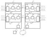
図1にPoint−to−Pointの一般的な光通信システム構成を示す。このシステムは、第1及び第2のSDH終端中継装置1,2を備え、機能別に分担されたモジュールが装置内スロットに実装されて通信が実現される。 FIG. 1 shows a general point-to-point optical communication system configuration. This system includes first and second SDH
第1のSDH終端中継装置1は、図上側のWest側15wと図下側のEast側15eとの二つの主信号系を有する。同様に、第2のSDH終端中継装置2は、図下側のWest側25wと図上側のEast側25eとの二つの主信号系を有する。そして第1及び第2のSDH終端中継装置1,2は伝送路3を通じて、第1のSDH終端中継装置1のWest側15wと第2のSDH終端中継装置2のEast側25eとが双方向通信し、第1のSDH終端中継装置1のEast側15eと第2のSDH終端中継装置2のWest側25wとが双方向通信し、運用系と非運用系が構成されている。 The first
第1のSDH終端中継装置1のWest側15wは、低速側モジュール11wと、クロスコネクト・モジュール12wと、高速側モジュール13wとを備えバス14で直列に接続され、同様にEast側15eは、低速側モジュール11eと、クロスコネクト・モジュール12eと、高速側モジュール13eとを備えバス14で直列に接続されている。また第2のSDH終端中継装置2のWest側25wは、低速側モジュール21wと、クロスコネクト・モジュール22wと、高速側モジュール23wとを備えバス24で直列に接続され、同様にEast側25eは、低速側モジュール21eと、クロスコネクト・モジュール22eと、高速側モジュール23eとを備えバス24によって直列に接続されている。 The
それぞれの低速側モジュール11w,11e,21w,21eは、外部装置との入出力ポートを二つ備え、伝送路3よりも狭帯域のインターフェース(例えば、STM−0、STM−1、ファースト・イーサーネット(登録商標)やギガビット・イーサーネット(登録商標)、ストレージ信号フォーマット等)を扱う。 Each of the low-
これらの入出力ポートから入力された信号(伝送データ)は、低速側モジュール11w,11e,21w,21eの内部で光−電気変換され、一旦GFP(Generic Framing Procedure)フレームにマッピングされた後、バーチャルコンカチネーション機能を用いて複数パス(VC3−XvまたはVC4−Xv)に集約され、クロスコネクト・モジュール12w,12e,22w,22eに送信される。なお、GFPは汎用フレームをSONET/SDHのフレームにマッピングする技術で、ITU(国際電気通信連合)において標準化されたものである。対応可能な汎用フレームの種類として、例えば、主にストレージ・ネットワークに使用されているギガビット級ネットワーク技術のファイバーチャネルのフレームや、イーサーネット(登録商標)のフレームがある。 Signals (transmission data) input from these input / output ports are photoelectrically converted in the low-
クロスコネクト・モジュール12w,12e,22w,22eは、低速側モジュール11w,11e,21w,21eから入力された伝送データを、所望のデータ伝送経路に設定し、高速側モジュール13w,13e,23w,23eへ送信する。 The
高速側モジュール13w,13e,23w,23eは、伝送データに対してSDH終端処理としてセクション・オーバーヘッドの付与や警報処理を施し、電気−光変換した後、伝送データをSTMパケットとして伝送路3へ送信する。 The high-
受信側は概ね送信側の逆の処理を行っており、ここでは説明を省略する。なお、本実施形態では入出力ポート数を2ポート(ポート1,ポート2)で記載しているが、これに限る趣旨ではない。また、クロスコネクト・モジュール12w,12e,22w,22eに接続する低速側モジュール11w,11e,21w,21eを1台で記載したが、複数台接続されてもよい。 The receiving side generally performs the reverse process of the transmitting side, and a description thereof is omitted here. In this embodiment, the number of input / output ports is described as two ports (
また、クライアント端末4が、第1のSDH終端中継装置1に備わる監視モジュール10と配線され、装置内バス(図示せず)を通じて第1のSDH終端中継装置1内の各モジュールの設定情報を読み書きしたり警報監視を行ったりする。さらに、クライアント端末4は、監視網5を通じて第2のSDH終端中継装置2内の監視モジュール20にアクセスし、対向装置である第2のSDH終端中継装置2の設定や監視を行う。 Further, the
つぎに、パスがバーチャルコカチネーションで集約され伝播する様子と、各モジュールの設定パラメータを説明する。図2は、パス構成の例を示している。ここでは図1の上段の主信号系(15w,25e)のみを表し、下段は同様であるので説明を省略する。 Next, how the paths are aggregated and propagated by virtual co-caching and the setting parameters of each module will be described. FIG. 2 shows an example of the path configuration. Here, only the upper main signal system (15w, 25e) in FIG. 1 is shown, and the lower part is the same, and the description is omitted.
図示のように、低速側モジュール11w,21eのポート1にVC4−5v(VC4#1〜#5)の帯域を、ポート2にVC4−2v(VC4#6,#7)の帯域を設け、各ポートはそれぞれVC終端点1、VC終端点2において、多重化されている。なお、#1〜#7は、タイムスロット番号ともいい、ある低速側モジュールにおいて集約されているバーチャルコカチネーションに対して順に付した番号である。チャンネルID(CH ID)はパケット多重分離時の宛先として使用される。チャンネルID1,3の伝送経路は、ポート1における第1のSDH終端中継装置1のWest側15wから、第2のSDH終端中継装置2のEast側25eへの伝送への向き(本図左から右)となっており、チャンネルID2,4の伝送経路はその反対向き(本図右から左)となっている。以下、主にチャンネルID1について説明する。 As shown in the figure, the VC4-5v (
低速側モジュール11wは、VC4に対し、高次VCの先頭位置である旨を示すAU(管理ユニット:administrative unit)ポインタを付与してAU4とする。例えば、VC4#1は、AU4#1となる。なお、ITU−T勧告では、2種類のAUが定義されており、VC3にその先頭位置を指示するポインタを付加したものをAU3といい、VC4にポインタを付加したものをAU4という。 The low-
つぎに、クロスコネクト・モジュール12wは、これらAUパスを高速側モジュール13w,23eのAU4フレームに順番に割り当て、SDH信号(VC4−7v)として第1のSDH終端中継装置1の高速側モジュール13wから、伝送路3を経由して第2のSDH終端中継装置2のに高速側モジュール23eに送信する。 Next, the
ところで、装置設定(コンフィグレーションの設定)の際には、従来はクライアント端末4から第1及び第2のSDH終端中継装置1,2に個別にアクセスしコンフィグレーション設定していた。そのような作業は、上述の通り、第1及び第2のSDH終端中継装置1,2に装着されるモジュール数やポート数によっては膨大になり、作業負担が大きかった。そこで、対向する装置同士の構成の対象性を利用して、自装置(例えば第1のSDH終端中継装置1)の設定情報を元に対向装置(例えば第2のSDH終端中継装置2)に反映させる。これによって、SDH終端中継装置の設定の煩雑さを低減する By the way, at the time of device setting (configuration setting), conventionally, the
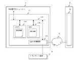
図3は、第1のSDH終端中継装置1の監視モジュール10の構成を示した図であり、クライアント端末4は第1のSDH終端中継装置1の監視モジュール10とLAN接続されており、外部インターフェースであるLAN終端回路101で終端された後、CPU102、メモリ103、第1のSDH終端中継装置1内の各モジュールとバス回線100によって並列に接続されている。 FIG. 3 is a diagram illustrating the configuration of the
CPU102はクライアント端末4からの指示に従い、メモリ103に設定情報(パラメータ)を書き込んで第1のSDH終端中継装置1内の各モジュールにコマンドを発する。したがって、CPU102とメモリ103はパラメータ設定部として機能する。 In accordance with an instruction from the
一方、本実施形態の特徴としてCPU102内に設定情報の一部を反転(入替)する演算機能を有しており、クライアント端末4の指示に基づき、メモリ103に保持している第1のSDH終端中継装置1の設定パラメータ情報をCPU102に読み出し、パラメータの所定箇所を入れ替える。つまり、CPU102とメモリ103は、他装置用パラメータ生成部として機能する。さらにCPU102は、入れ替え情報(入れ替えずそのまま適用する共通設定情報を含む)を対向装置である第2のSDH終端中継装置2に送信させる。 On the other hand, as a feature of the present embodiment, the
対向装置である第2のSDH終端中継装置2では、この入れ替え情報(第2のSDH終端中継装置2の設定パラメータ情報)を第2のSDH終端中継装置2のメモリに書き込み、第2のSDH終端中継装置2の各モジュールにコマンド実行することによって、第2のSDH終端中継装置2の設定を完了する。なお、監視モジュール10,20の内部構成は同一であるので、監視モジュール20の内部は省略して記載している。 In the second SDH
クライアント端末4から第1及び第2のSDH終端中継装置1,2に指示するメッセージとして、テレコミニュケーション分野で一般的に使用されるTL1(トランザクション言語1)を用いている。TL1のメッセージは主にモジュールやファシリティ(ライン(ポート)などの回線)を特定するAID(アクセスID)をコマンド後に付与する形式となっており、人間に読解可能な特徴がある。 As a message for instructing the first and second SDH
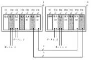
そこで図1のシステム構成を例に、第1及び第2のSDH終端中継装置1,2に実装するモジュールの配置を図4に示す。第1及び第2のSDH終端中継装置1,2は、それぞれスロット番号0から6(SL0〜SL6)まで7個のスロットルを備えている。監視モジュール10,20はスロット番号0(SL0)に実装され、West側15w,25wのモジュールは奇数のスロット番号(SL1,SL3,SL5)に、East側15e,25eのモジュールは偶数のスロット番号(SL2,SL4,SL6)に実装するよう、予め決められている。 Therefore, taking the system configuration of FIG. 1 as an example, the arrangement of modules mounted on the first and second SDH
また、同一機能を有するモジュールは隣り合うスロットに実装される。具体的には、スロット番号1(SL1)には、West側15w,25wの低速側モジュール11w,21wが実装される。スロット番号2(SL2)には、East側15e,25eの低速側モジュール11e,21eが実装される。スロット番号3(SL3)には、West側15w,25wのクロスコネクト・モジュール12w,22wが実装される。スロット番号4(SL4)には、East側15e,25eのクロスコネクト・モジュール12e,22eが実装される。スロット番号5(SL5)には、West側15w,25wの高速側モジュール13w,23wが実装される。スロット番号6(SL6)には、East側15e,25eの高速側モジュール13e,23eが実装される。 Modules having the same function are mounted in adjacent slots. Specifically, the low-
従って、自装置(第1のSDH終端中継装置1)と対向装置(第2のSDH終端中継装置2)で同一機能を有するモジュールのスロット番号の組み合わせ、つまり隣り合うスロットの組合せは、(SL1,SL2)、(SL3,SL4)、(SL5,SL6)となり、スロット番号はこの組み合わせの中で入れ替わる。例えば、自装置のある機能のモジュールが実装されているスロット番号が「SL1」であれば、対向装置側は「SL2」となる。 Therefore, the combination of slot numbers of modules having the same function in the own device (first SDH termination relay device 1) and the opposite device (second SDH termination relay device 2), that is, the combination of adjacent slots is (SL1, SL2), (SL3, SL4), (SL5, SL6), and the slot numbers are switched in this combination. For example, if the slot number in which a module of a certain function of the own device is mounted is “SL1”, the opposite device side is “SL2”.
図4において、墨塗りして示しているたモジュール(11w〜13w,21e〜23e)は、図1の上段の主信号経路(15w,25e)を示している。一方、スロット番号SL0を除いた墨塗りされていないモジュール(11e〜13e,21w〜23w)は、図1の下段の主信号経路(15e,25w)を示している。 In FIG. 4, the modules (11w to 13w, 21e to 23e) shown in black are the main signal paths (15w and 25e) in the upper part of FIG. On the other hand, the modules (11e to 13e, 21w to 23w) not excluding the slot number SL0 indicate the main signal paths (15e, 25w) in the lower part of FIG.
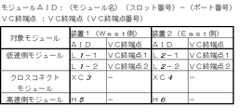
図5〜図7は図1の上段側の主信号系(15w,25e)を例にした設定情報(AIDを含む)を示しており、この設定情報を設定することをコンフィグレーション設定という。本来、AIDには架番号、シェルフ番号などが付与されたり、図1の構成例では部分的に固定値であったりするが、ここでは簡略化して記載している。 5 to 7 show setting information (including AID) taking the upper main signal system (15w, 25e) of FIG. 1 as an example, and setting this setting information is called configuration setting. Originally, AID is assigned a rack number, a shelf number, or the like, or in the configuration example of FIG.
図5〜図7において、第2のSDH終端中継装置2に対し第1のSDH終端中継装置1でパラメータが入れ替わっている箇所を斜体字で示している。なお、第1及び第2のSDH終端中継装置1,2の共通した設定パラメータ、例えば伝送方式の種別(SONET又はSDH)、信号波長(850nm又は1310nm)、レーザーの駆動制御方法(オートレーザーシャットダウンなど)等はここでは省略している。 In FIG. 5 to FIG. 7, the portions where the parameters are switched in the first SDH
図5は、モジュール登録(ポートを含む)とVC終端点登録に関する情報を示した表である。AIDは、スロット番号とポート番号(クロスコネクト・モジュール、高速側モジュールでは省略)で表現しており、VC終端点1、VC終端点2をポート1,2に割り当てた状態を示している。なお、表中のL、XC、Hはそれぞれ低速側モジュール、クロスコネクト・モジュール、高速側モジュールの略称である。また、表中の「装置1」は「第1のSDH終端中継装置1」を、「装置2」は「第2のSDH終端中継装置2」を意味している。例えば、表中における「L1−2」は、低速モジュール(L)がスロット番号1(SL1)に実装されており、ポート番号がポート2である旨を示している。また、表中の「XC3」は、クロスコネクト・モジュール(XC)が、スロット番号3(SL3)に実装されていることを示し、「H5」は高速側モジュールがスロット番号5(SL5)に実装されていることを示している。本図で示すように、第1のSDH終端中継装置1と第2のSDH終端中継装置2とでは、それぞれのAIDのスロット番号が、上述した組み合わせとなるように入れ替わっている。なお、入れ替わっている箇所を斜体字で示しており、この入れ替えが上述した「設定情報の一部を反転する演算」にあたる。 FIG. 5 is a table showing information related to module registration (including ports) and VC termination point registration. The AID is expressed by a slot number and a port number (omitted in the cross-connect module and the high-speed module), and indicates a state in which the
図6はチャンネルIDの設定を示した表であり、スロット番号が入れ替わるだけでなく送信元と送信先も入れ替わることに注意が必要である。 FIG. 6 is a table showing channel ID settings. Note that not only the slot numbers are switched, but also the transmission source and the transmission destination are switched.
図7は低速モジュールと高速モジュールのAU登録ならびに、クロスコネクト・モジュール(XC)で双方のAUパスがタイムスロット番号順に割り当てられていることを示す。AU4もまた、AIDで表記されている。 FIG. 7 shows that the AU registration of the low-speed module and the high-speed module and that both AU paths are assigned in the order of time slot numbers in the cross-connect module (XC). AU4 is also indicated by AID.
図3において、クライアント端末4から第1のSDH終端中継装置1を設定する場合、CPU102はバス100を通じてメモリ103に、AIDを含む全ての設定情報(West側15wとEast側15e)を書き込み、AIDで指定された対象にTL1メッセージを実行する。すなわちメモリ103には第1のSDH終端中継装置1の全ての設定情報が書き込まれ、保存されている。 In FIG. 3, when setting the first SDH
対向装置である第2のSDH終端中継装置2を設定する場合、クライアント端末4は第1のSDH終端中継装置1にアクセスし、第1のSDH終端中継装置1のCPU102にメモリ103に保存された全設定情報(West側とEast側)を読み込ませ、該当する箇所(図5〜図7の斜線字部分)を入れ替えて第2のSDH終端中継装置2へ送信する。なお、第1及び第2のSDH終端中継装置1,2で共通の設定情報も送信される。 When setting the second SDH
第2のSDH終端中継装置2では第2のSDH終端中継装置2内の作業領域としてのメモリに、入れ替え情報が書き込まれ、第2のSDH終端中継装置2内のCPUが指定された対象にTL1メッセージを実行することによって、パラメータ設定部として機能するメモリに記憶され、第2のSDH終端中継装置2の設定が完了する。 In the second SDH
以上、本実施形態によれば、光通信装置のコンフィグレーション設定時に、自装置と対向して接続される対向装置の設定情報が、自装置との対称性を利用した情報をもとに設定できるので、対向装置の設定が簡素化できる。 As described above, according to the present embodiment, when configuring the configuration of the optical communication apparatus, the setting information of the opposite apparatus connected to face the own apparatus can be set based on information using symmetry with the own apparatus. Therefore, the setting of the opposing device can be simplified.
なお、本発明は上記した実施形態に限定されるものではなく、本発明の要旨を逸脱しない範囲内において種々変更を加え得ることは勿論である。例えば、第2の実施形態として、図8に示すように装置がタンデム接続するシステム構成の場合、West側又はEast側を選別してCPUがメモリから設定パラメータ情報を読み出しても良い。その場合、第2のSDH終端中継装置2のWest側、East側の設定パラメータは第1のSDH終端中継装置1のEast側、第3のSDH終端中継装置6のWest側をそれぞれ入れ替えた情報となる。モジュールの実装位置はWest側、East側でスロット番号が奇数、偶数で分かれているので、容易に選別することができる。 Note that the present invention is not limited to the above-described embodiment, and it is needless to say that various modifications can be made without departing from the gist of the present invention. For example, as a second embodiment, in the case of a system configuration in which the devices are connected in tandem as shown in FIG. 8, the CPU may read out the setting parameter information from the memory by selecting the West side or the East side. In this case, the setting parameters on the West side and the East side of the second SDH
また、対向装置用設定情報は、監視網5を経由して、自装置から対向装置へ伝送されたがこれに限らず、例えば、記録メディアに対向装置用設定情報を書き込み、対向装置に接続された所定の記録装置によって読み出し、読み出した対向装置用設定情報を、対向装置の設定情報として反映させる態様であってもよい。 In addition, the counter device setting information is transmitted from the own device to the counter device via the
本発明は、光通信装置において広く利用できる。 The present invention can be widely used in optical communication apparatuses.
1・・・第1のSDH終端中継装置
2・・・第2のSDH終端中継装置
3・・・伝送路
4・・・クライアント端末
5・・・監視網
6・・・第3のSDH終端中継装置
10,20・・・監視モジュール
11e,11w,21e,21w・・・低速側モジュール
12e,12w,22e,22w・・・クロスコネクト・モジュール
13e,13w,23e,23w・・・高速側モジュール
14,24・・・バス
15e,25e・・・East側
15w,25w・・・West側
100・・・バス回線
101・・・LAN終端回路
102・・・CPU
103・・・メモリDESCRIPTION OF
103 ... Memory
Claims (7)
Translated fromJapanese光通信のための設定情報として複数のパラメータを設定するパラメータ設定部と、
光通信に関する内部構成に当該光通信装置と対称性を有する他の光通信装置に設定すべき他装置用の設定情報を、対称性を有する内部構成に関する所定のパラメータを入れ替えて生成する他装置用パラメータ生成部と、
を備えることを特徴とする光通信装置。An optical communication device used for optical communication,
A parameter setting unit for setting a plurality of parameters as setting information for optical communication;
For other devices that generate setting information for other devices that should be set in another optical communication device that has symmetry with the optical communication device in the internal configuration related to optical communication, by replacing predetermined parameters related to the inner configuration that has symmetry A parameter generator;
An optical communication device comprising:
前記他装置用パラメータ生成部は、前記第1又は第2の主信号系に設定されている設定情報を選別し、選別された設定情報の所定のパラメータを前記対称性を反映させて入れ替えることを特徴とする請求項1から3までのいずれかに記載の光通信装置。As the main signal system, it has first and second main signal systems,
The other apparatus parameter generation unit selects the setting information set in the first or second main signal system, and replaces a predetermined parameter of the selected setting information to reflect the symmetry. 4. The optical communication device according to claim 1, wherein the optical communication device is characterized in that:
光通信のための設定情報を光通信に関する内部構成に対称性を有している他の光通信装置から、対称性を有している内部構成に関するパラメータを入れ替えて取得する手段を備えたことを特徴とする光通信装置。An optical communication device used for optical communication,
Means for obtaining setting information for optical communication by exchanging parameters relating to the internal configuration having symmetry from another optical communication device having symmetry in the internal configuration relating to optical communication; An optical communication device.
一方の光通信装置において、光通信のために必要となる設定情報として複数のパラメータを設定する第1の設定工程と、
前記設定情報として設定された複数のパラメータのうち、対称性を有する装置内の構成に関するパラメータをその対称性を反映させて入れ替え、他方の光通信装置の設定情報を生成する他装置設定情報生成工程と、
前記他方の光通信装置に、前記他装置設定情報生成工程で生成された設定情報を反映させる第2の設定工程と
を有することを特徴とするとコンフィグレーション設定方法。A configuration setting method for setting setting information in an optical communication system in which two optical communication devices having symmetry with each other in a configuration related to optical communication are connected,
In one optical communication apparatus, a first setting step for setting a plurality of parameters as setting information necessary for optical communication;
Other device setting information generation step of generating a setting information of the other optical communication device by replacing a parameter related to the configuration in the device having the symmetry among the plurality of parameters set as the setting information to reflect the symmetry When,
A configuration setting method comprising: a second setting step of reflecting the setting information generated in the other device setting information generation step in the other optical communication device.
Priority Applications (1)
| Application Number | Priority Date | Filing Date | Title |
|---|---|---|---|
| JP2007086651AJP2008245206A (en) | 2007-03-29 | 2007-03-29 | Optical communication system and configuration setting method |
Applications Claiming Priority (1)
| Application Number | Priority Date | Filing Date | Title |
|---|---|---|---|
| JP2007086651AJP2008245206A (en) | 2007-03-29 | 2007-03-29 | Optical communication system and configuration setting method |
Publications (1)
| Publication Number | Publication Date |
|---|---|
| JP2008245206Atrue JP2008245206A (en) | 2008-10-09 |
Family
ID=39915934
Family Applications (1)
| Application Number | Title | Priority Date | Filing Date |
|---|---|---|---|
| JP2007086651APendingJP2008245206A (en) | 2007-03-29 | 2007-03-29 | Optical communication system and configuration setting method |
Country Status (1)
| Country | Link |
|---|---|
| JP (1) | JP2008245206A (en) |
- 2007
- 2007-03-29JPJP2007086651Apatent/JP2008245206A/enactivePending
Similar Documents
| Publication | Publication Date | Title |
|---|---|---|
| US11700083B2 (en) | Method and apparatus for processing service data in optical transport network | |
| US7826741B2 (en) | Optical network system | |
| JP5061667B2 (en) | Optical transmission device accommodating multirate signals | |
| JPWO2006106973A1 (en) | Optical communication method, optical communication apparatus, and optical communication system | |
| JP2003188919A (en) | Network, switch device, method for processing otn frame to be used therefor, its circuit and integrated circuit | |
| US11223422B2 (en) | Method and apparatus for processing ethernet data in optical network, and system | |
| WO2019047110A1 (en) | Delay measurement method and apparatus, and system in optical transport network | |
| US12407438B2 (en) | Signal frame processing method and related device | |
| US20050117905A1 (en) | Optical transponder which can be reconfigured in accordance with various types of client networks | |
| EP2472803B1 (en) | Method, apparatus, system for hybrid-transmitting and bridging of circuit service and packet service | |
| EP2579520A1 (en) | Bandwidth allocation method and device for realizing bandwidth allocation | |
| CN120167112A (en) | Bandwidth adjustment method and device | |
| JP2008245206A (en) | Optical communication system and configuration setting method | |
| WO2020001497A1 (en) | Optical transport system device, conversion unit, conversion method, and storage medium | |
| US8374500B2 (en) | SONET/SDH transmission apparatus | |
| US9077469B2 (en) | Adapting apparatus and method | |
| CN115314103B (en) | Data transmission method, device and chip of optical transmission network | |
| WO2020051851A1 (en) | Data transmission method and apparatus in optical transport network | |
| US7639677B2 (en) | Optical transponder having switching function | |
| CN116489704A (en) | Method for transmitting data | |
| JP3816909B2 (en) | Node monitoring and control device for optical network | |
| EP4593311A1 (en) | Data transmission method and apparatus | |
| KR100628330B1 (en) | Optical transponder having switching function | |
| WO2022194290A1 (en) | Method, apparatus and system for processing ethernet data in optical network | |
| Berger et al. | Versatile bandwidth management: The design, development, and deployment of LambdaUnite® |