JP2008242544A - Collision avoidance apparatus and method - Google Patents
Collision avoidance apparatus and methodDownload PDFInfo
- Publication number
- JP2008242544A JP2008242544AJP2007078122AJP2007078122AJP2008242544AJP 2008242544 AJP2008242544 AJP 2008242544AJP 2007078122 AJP2007078122 AJP 2007078122AJP 2007078122 AJP2007078122 AJP 2007078122AJP 2008242544 AJP2008242544 AJP 2008242544A
- Authority
- JP
- Japan
- Prior art keywords
- collision avoidance
- safety ensuring
- ensuring area
- area
- avoidance device
- Prior art date
- Legal status (The legal status is an assumption and is not a legal conclusion. Google has not performed a legal analysis and makes no representation as to the accuracy of the status listed.)
- Pending
Links
Images


Classifications
- G—PHYSICS
- G08—SIGNALLING
- G08G—TRAFFIC CONTROL SYSTEMS
- G08G1/00—Traffic control systems for road vehicles
- G08G1/16—Anti-collision systems
- G08G1/167—Driving aids for lane monitoring, lane changing, e.g. blind spot detection
- G—PHYSICS
- G08—SIGNALLING
- G08G—TRAFFIC CONTROL SYSTEMS
- G08G1/00—Traffic control systems for road vehicles
- G08G1/16—Anti-collision systems
- G08G1/165—Anti-collision systems for passive traffic, e.g. including static obstacles, trees
- G—PHYSICS
- G08—SIGNALLING
- G08G—TRAFFIC CONTROL SYSTEMS
- G08G1/00—Traffic control systems for road vehicles
- G08G1/16—Anti-collision systems
- G08G1/166—Anti-collision systems for active traffic, e.g. moving vehicles, pedestrians, bikes
Landscapes
- Physics & Mathematics (AREA)
- General Physics & Mathematics (AREA)
- Traffic Control Systems (AREA)
- Steering Control In Accordance With Driving Conditions (AREA)
- Control Of Driving Devices And Active Controlling Of Vehicle (AREA)
Abstract
Translated fromJapaneseDescription
Translated fromJapanese本発明は、移動体における衝突回避技術に関する。 The present invention relates to a collision avoidance technique in a moving body.
移動体の安全性向上のために、衝突回避技術が様々に開発されている。例えばレーダやカメラにより他の移動物体(以下「他移動体」とする)を検出し、検出した他移動体までの距離と相対速度により衝突するまでの予測時間を計算し、その予測時間が閾値以下の場合に減速を行うことが知られている。 Various collision avoidance techniques have been developed to improve the safety of moving objects. For example, another moving object (hereinafter referred to as “another moving object”) is detected by a radar or a camera, and the predicted time until the collision is detected based on the detected distance to the other moving object and the relative speed is calculated. It is known to perform deceleration in the following cases.
このような衝突回避装置の課題の一つとして、複数の他移動体が存在する場合の減速判定が難しいこと、またその制御が複雑であることが挙げられる。これを解決するために、自分の移動体(以下「自移動体」とする)の近傍に安全確保領域を定め、その安全確保領域に他移動体が進入する場合に衝突回避や警報を行うことが知られており、その具体例として、安全確保領域を自移動体に一つ設定する方法(例えば特許文献1)、また自移動体ではなく、他移動体それぞれに安全確保領域を設定する方法(例えば特許文献2)が知られている。 One of the problems with such a collision avoidance device is that it is difficult to determine deceleration when there are a plurality of other moving bodies, and that the control is complicated. In order to solve this problem, a safety area is set near the user's own mobile body (hereinafter referred to as “own mobile body”), and collision avoidance and warning are given when another mobile body enters the safety area. As a specific example, there is a method for setting one safety ensuring area in the own mobile body (for example, Patent Document 1), and a method for setting a safety ensuring area in each of the other mobile bodies instead of the self mobile body. (For example, patent document 2) is known.
また安全確保領域の形状としては、安全確保領域を自移動体の現在の進路方向の形状に合わせ安全確保領域を変形させる方法(例えば特許文献3)が知られている。 As a shape of the safety ensuring area, there is known a method (for example, Patent Document 3) in which the safety ensuring area is deformed by matching the safety ensuring area with the current shape of the moving body.
しかし、上記従来技術は、例えば自移動体から横方向に遠ざかる他移動体に対しても減速制御を行う可能性があること、また自移動体の進路変更予定を他移動体が持つ安全確保領域に反映させることが困難であったため、安全確保領域を設定した後に、別途自車の進行予定方向を反映させるロジック判定が必要となり、計算量の観点から好ましくなかった。 However, the above-mentioned conventional technology has a possibility of performing deceleration control even for other moving bodies moving away from the own moving body, for example, and a safety ensuring area in which the other moving body has a course change schedule of the own moving body. Since it was difficult to reflect this in the vehicle, it was not preferable from the viewpoint of the calculation amount because it was necessary to separately make a logic determination that reflected the planned traveling direction of the vehicle after setting the safety ensuring area.
本発明は、より簡易で精度の高い衝突回避技術を提供することを目的とする。 An object of the present invention is to provide a collision avoidance technique that is simpler and more accurate.
本発明は、対象物と自移動体との間の相対物理量に応じて自移動体の周囲の仮想的な安全確保領域を決定し、当該安全確保領域に他移動体が進入すると判定した場合に、回避制御または警報を行う。 The present invention determines a virtual safety ensuring area around the moving object according to the relative physical quantity between the object and the moving object, and determines that another moving object enters the safety ensuring area. , Do avoidance control or alarm.
本発明によれば、より簡易で精度の高い衝突回避技術が得られる。 According to the present invention, a simpler and more accurate collision avoidance technique can be obtained.
以下、移動体として自動車に適用した場合の実施形態を示すが、本発明はこれに限らず、移動体であれば適用可能である。 Hereinafter, although the embodiment at the time of applying to a car as a mobile object is shown, the present invention is not limited to this, and can be applied to any mobile object.
図1は、本発明の一実施形態をなす衝突回避装置のブロック構成図を示す。 FIG. 1 is a block diagram of a collision avoidance device according to an embodiment of the present invention.
本システムでは、車両に設置されたレーダ101,カメラ102により他車や歩行者を検出し、自車前方道路形状取得部105により取得した自車の前方と横方向の道路形状,自車の位置,速度,進行方向取得部104により取得した自車の位置とレーンを、入力部111を介して入力し、安全確保領域延伸計算部106で安全確保領域を計算する。そして、他車安全確保領域進入判定部107にて他車が安全確保領域に進入している、または進入すると予測される場合に、自車の減速度・速度・ハンドル設定部108により、回避行動のプランを立て、出力部110を介して速度・ハンドル制御部109にそのプランを送り、自車の回避行動を行う。なお、本衝突回避装置または方法は、ナビまたはCPU
(Central Processing Unit) を持つコントローラ上で動くプログラムで実現され処理が行われる。また、ここでは回避行動のプランを実行させるための信号(指令信号でも良いし、また、単に「進入する」という信号を出力してもよい。「進入する」という信号を出力する場合は、信号受信側で回避行動のプランを決定しても良い)出力部110を介して速度・ハンドル制御部109に送っているが、単に警報を出力しても良い。その場合は、出力部110が警報を出力させるための信号を出力し、受信側で既知の警報出力処理を行っても良い)。次に図1の各部の詳細について説明する。In this system, other vehicles and pedestrians are detected by the
Realized and processed by a program running on a controller with a (Central Processing Unit). Further, here, a signal for executing an avoidance action plan (a command signal may be used, or a signal “entry” may be output. When a signal “entry” is output, The plan of avoidance action may be determined on the receiving side), which is sent to the speed /
レーダ101,カメラ102は車に設置され他車,歩行者,障害物,走行中のレーンを検出し、物体認識部103へその情報を送る。情報の種類としては、他車,歩行者や障害物までの距離(自車からみた),方位(自車の進行方向からのずれ),絶対速度,自車との相対速度,どのレーンを走行しているかおよび、レーンの左または右端からの距離とする。 The
レーダによる他車や障害物の一検出方法としては「安全走行支援システムを支える環境認識技術,日立評論,Vol85,No.5,pp.43−46,2004年5月」に挙げられる、ミリ波を射出しその反射波を受信し、自車の前方に存在する物体までの距離,相対速度,角度を計測する方法がある。他に、レーザーやマイクロ波を使用したレーダを用いても良い。 One method of detecting other vehicles and obstacles using radar is listed as "Environmental recognition technology supporting safe driving support systems, Hitachi review,
またカメラによる他車の認識方法としては、特開2005−156199号公報に挙げられる方法がある。これは、カメラにより前方の車両の輝度変化によりエッジ点を抽出しエッジ点を解析する方法である。また本方法は、レーダとのセンサーフュージョンにより誤差を低減している。カメラによる歩行者の検知方法として、例えばステレオカメラを用い視差により距離を求める方法がある。カメラによるレーンの認識技術としては「安全走行支援システムを支える環境認識技術,日立評論,Vol85,No.5,pp.43−46,2004年5月」がある。 As a method for recognizing other vehicles by a camera, there is a method described in JP-A-2005-156199. This is a method of extracting an edge point from a brightness change of a vehicle ahead by a camera and analyzing the edge point. The method also reduces errors by sensor fusion with the radar. As a method for detecting a pedestrian using a camera, for example, there is a method of obtaining a distance by parallax using a stereo camera. As a technology for recognizing a lane by a camera, there is "Environment recognition technology for supporting a safe driving support system, Hitachi review,
次に、物体認識部103について説明する。物体認識部103は、レーダ101,カメラ102もしくは、インフラ通信や車間通信により知り得た、他の対象物(例えば他移動体としての他車や歩行者,障害物を含む地物,緯度や経度を含む地点,道路形状を含む地形,後述するスクールゾーンなどの地域情報)までの距離,方位と、絶対速度,自車との相対速度、自車が車線からどの程度ずれてまたはシフトして走行しているかの情報を集計し、センサーフュージョンにより、他の対象物の全ての相対位置関係,相対速度および方向の精度を高め、自車と他の物体(他車,歩行者,障害物)の相対位置マップ、および相対速度方向ベクトルを生成し、入力部111を介して安全確保領域延伸計算部106に情報を渡す。このマップと相対速度方向ベクトルのマップ例を図2に示す。図2のマップでは自車1の先頭部分を原点202とし、自車1の進行方向をy軸203,進行方向と垂直の方向をx軸204とする。ここでは、レーダやカメラにて検出され、センサーフュージョンにより精度を高めた位置、相対速度に応じて、他車205,206、および歩行者
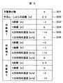
207がプロットされている。また自車1との相対速度とその方向ベクトル208,209,210が、それぞれ他車205,206、歩行者207に同時にプロットされる。そして、カメラにより認識された車線211が表示される。この図2の画像は仮想的なものであり、実際には図3の数値テーブルが保持される。図3は、対象物(他車,歩行者,障害物)の個数301,車線からの距離302,それぞれの他の物体毎のx方向とy方向の相対位置(303,304),x方向とy方向の相対速度(305,306)の値が記憶される。Next, the
次に、自車の位置,速度,進行方向取得部104について説明する。自車の位置,速度,進行方向取得部104は、自車の走行位置をナビゲーションのGPS(Global
Positioning System)から東経,北緯,進行方向,絶対速度,高度を取得する。ここでの方位はジャイロや地磁気により補正をかけても良い。速度は、自車にある速度センサの値を使用しても良い。また、ビーコンから受信した位置補正信号により自車の位置を補正しても良い。また、取得した位置,絶対速度,高度は、入力部111を介して自車前方道路形状取得部105,安全確保領域延伸計算部106に転送する。Next, the position, speed, and traveling
Acquire east longitude, north latitude, direction of travel, absolute speed, and altitude from Positioning System. The direction here may be corrected by a gyroscope or geomagnetism. As the speed, a value of a speed sensor in the own vehicle may be used. Further, the position of the vehicle may be corrected by the position correction signal received from the beacon. Further, the acquired position, absolute speed, and altitude are transferred to the own vehicle forward road
この自車の位置,速度,進行方向取得部104は、上記の他に地域の情報、例えば日付,時間情報,スクールゾーン,市街地/繁華街/郊外などの特性,天候情報,工事中や過去の経験則による危険地点・危険地域情報などを提供しても良い。後述する安全確保領域延伸計算部106は、これらの情報に応じて安全確保領域を決定しても良い。例えばスクールゾーンの場合は安全確保領域をスクールゾーンとは異なる地域の安全確保領域と比較して大きく設定する。 In addition to the above, the location, speed, and traveling
尚、この実施形態では物体認識部103,自車の位置,速度,進行方向取得部104,自車前方道路形状取得部105は、入力部111を介して安全確保領域延伸計算部106に情報を入力する例を示すが、この入力部111は、物体認識部103,自車の位置,速度,進行方向取得部104,自車前方道路形状取得部105が装置外部の例えばカメラやレーダ,ナビゲーション装置に内蔵された機能であり、そこから車内LANやコネクタなどを通じて入力する場合のインターフェースに対応するものである。従って、物体認識部103,自車の位置,速度,進行方向取得部104,自車前方道路形状取得部105の少なくとも一つが本実施形態の衝突安全装置に別CPUとして内蔵されている場合はその信号結線であっても良い。また、これらの機能がアプリケーションやドライバとして衝突安全装置に内蔵されている場合には、入力部111は例えば当該アプリケーションやドライバとのそのソフトウェアとのインターフェースソフトウェアになる。自車前方道路形状取得部105が衝突安全装置に内蔵されている形態では、自車の位置,速度,進行方向取得部104と自車前方道路形状取得部105との間に入力部111が介在する構成になる。さらに、本実施形態の衝突安全装置は、エンジン制御装置や車間距離制御装置,統合制御装置などに内蔵されていても良い。これは、出力部110にも同様である。 In this embodiment, the
次に、進行方向取得方法について述べる。進行方向取得としては、方向指示器やハンドル操舵角センサにより取得する、またはナビゲーションにて予め設定した経路により、右左折地点が判るため、右左折地点に近づいたときにレーンチェンジタイミングを予測する。ナビゲーションにより、予め設定した経路には、右左折のタイミング予定が記録されているため、右左折前のレーンチェンジタイミングを予測することができる。レーンチェンジ(進行方向の予定)は例えば「直進,右折,左折,左レーン移動,右レーン移動」のいずれかとする。 Next, the traveling direction acquisition method will be described. As the traveling direction acquisition, the lane change timing is predicted when approaching the right / left turn point because the right / left turn point is obtained from a direction indicator, a steering wheel angle sensor, or a route set in advance by navigation. By navigation, since a schedule of right / left turns is recorded on a predetermined route, the lane change timing before the right / left turns can be predicted. The lane change (schedule in the traveling direction) is, for example, any one of “straight, right turn, left turn, left lane movement, right lane movement”.
自車前方道路形状取得部105は、自車の位置,速度,進行方向取得104で取得した自車の位置と進行方向、および高度より、地図を参照し、自車の近傍の道路地図を切り出す。ここでの道路地図情報としては、例えば道路の形状,レーン運用,自車の進行方向の道路形状のマップの情報とする。このマップ情報と画面情報と自車が移動する予定と隣り合うレーンを安全確保領域延伸計算部106へ送る。 The own vehicle forward road
安全確保領域延伸計算部106は、検出した他の対象物(他車,歩行者)それぞれに対して安全確保領域を設定し、延伸計算を行う。すなわち、対象物の相対物理量に応じて自移動体の周囲の仮想的な安全確保領域を決定するものである。この安全確保領域の形状設定例として図4の例を用いて説明する。 The safety area
図4は、自車1に対して、台形状の安全確保領域42を設定した例である。この台形の上底43と下底44は、自車1の進行方向45に垂直になるように設定する。ここで、下底の長さは、自車1のドアが開いたときの幅とし、自車1のドアが急に開いたとしても他車に衝突しないようにするためのマージンである。上底の長さは、下底の長さより長くする。これは、自車1の進行方向のぶれによって横方向にずれることを表現しているため、この安全確保領域により遠くの車に衝突するリスクを回避できる。このぶれの幅は、予めドライバのハンドルのぶれの傾向に応じて設定しておく。または、予め定数を設定しても良い。この構成により、自車1の進路が横方向にぶれたとしても他の移動物体に衝突するリスクを下げることが可能である。 FIG. 4 is an example in which a trapezoidal
また、安全確保領域を他の移動物体方向、または変更予定の航路方向に伸ばす場合に、安全確保領域の幅を、自車の絶対速度が低い場合には広く、自車の絶対速度が高い場合には狭くしても良い。 Also, when extending the safety area toward other moving objects or the direction of the route to be changed, the width of the safety area is wide when the vehicle's absolute speed is low and the vehicle's absolute speed is high. It may be narrow.
この例では台形を示したが、自車1から遠くになるにつれ広がる閉曲線でも良い。次に、安全確保領域42の左側の角度θ1(46)と、右側の角度θ2(47)の設定方法について述べる。この例では、安全確保領域が左右対称であり、θ1=θ2となるため、
θ1を上底と下底の長さから式1により求められる。In this example, a trapezoid is shown, but a closed curve that widens as the distance from the
θ1 can be obtained from the lengths of the upper and lower
θ1=atn[(上底長−下底長)/2×安全確保領域の長さ] …式1
atn:関数atnの逆関数であり、角度を求める関数
次に、安全確保領域の長さについて説明する。安全確保領域の長さは、自車1の絶対速度、または物体との相対速度に基づいて計算しても良い。後者の場合には、自車1が減速するときの減速度と相対速度により前方の車にぶつかるまでの距離となり、式2で示される。θ1 = atn [(upper base length−lower base length) / 2 × length of safety ensuring area]
atn: an inverse function of the function atn and a function for obtaining an angle Next, the length of the safety ensuring area will be described. The length of the safety ensuring area may be calculated based on the absolute speed of the
安全確保領域の長さ=空走時間×相対速度+相対速度二乗×2/最大減速度 …式2
この相対速度として、進行方向成分の相対速度、または相対速度ベクトルの絶対値を用いても良い。また、自車1の前方に他車が存在し、式2で求めた長さが負、即ち他車が自車1から離れていく場合には、安全確保領域を設定しない、または安全確保領域の最小単位(駐車スペースの長方形)を設定しても良い。式2の空走時間は、制御指令を出してから制御のかかる時間であり、予めシステムに設定しておく。この値を0としても良い。式2の最大減速度はシステムの制動の減速度であり、予めこの値は設定しておく。この値として0.2G(Gは重力加速度)としても良い。Length of safety ensuring area = idling time x relative speed + relative speed square x 2 / maximum deceleration ...
As this relative speed, the relative speed of the traveling direction component or the absolute value of the relative speed vector may be used. In addition, when there is another vehicle in front of the
ここで、安全確保領域として自車1の絶対速度を用いる場合には、安全確保領域の長さとして、式2の相対速度を自車1の絶対速度と置き換えて計算しても良い。 Here, when the absolute speed of the
図4で示される安全確保領域は、他の物体(例えば、他車や歩行者)それぞれ専用の安全確保領域を自車1に持たせる、あるいは別途自車1に、自車1の絶対速度に応じた安全確保領域を持たせても良い。 In the safety ensuring area shown in FIG. 4, the
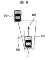
次に、他車の方向に安全確保領域を延ばす例を、図5で説明する。図5の例は、自車1の進行方向52から左横方向に外れた方向に、他車53が存在している。この場合には、左右非対称の台形の安全確保領域54を設定する。このとき、上底の左半分の延伸長として、他車との横方向の相対速度を元に式3と設定しても良い。 Next, an example of extending the safety ensuring area in the direction of the other vehicle will be described with reference to FIG. In the example of FIG. 5, the
上底左半分の延伸長
=空走時間×横方向相対速度+横方向相対速度二乗×2/最大減速度 …式3
また式3が負の値となる場合には、上底左半分の延伸長を0とする、または定数としても良い。Stretch length of upper left half = idle running time x transverse relative speed + transverse relative speed squared
When
また、左側の角度θ1(55)の値は、式4となる。 Also, the value of the left angle θ1 (55) is given by Equation 4.
θ1=atn[上底左半分の延伸長/安全確保領域の長さ] …式4
図5の例では、左側に他車が存在する例であるが、右側に他車が存在する場合でも右と左が入れ替わるのみで、同様な考え方を適用する。θ1 = atn [extension length of upper left half / length of safety ensuring area] Formula 4
The example of FIG. 5 is an example in which another vehicle is present on the left side, but the same concept is applied only when the right and left are interchanged even when another vehicle is present on the right side.
次に、他車が複数台存在する場合の安全確保領域の設定方法について図6を用いて説明する。図6では、自車1の進行方向に他車62,自車1の左前方に他車63が存在する。この2台の他車が存在する場合には、それぞれの他車に応じ、自車1に安全確保領域64,65の2つを、自車1に設定する。ここで、安全確保領域64は、自車1の進行方向にある他車62に対応し、この場合には横にずれていないため左右対称の台形を設定する。安全確保領域65は、自車1の左前方の他車63に対応し、この場合には他車63が自車1に対して左にあるため、左方向に形状が伸びている。ここで、それぞれの安全確保領域は、前述する相対速度に応じた長さを設定することにより、自車1から遠ざかる車の安全確保領域は小さくなり、結果的に制動がかからないようになる。また、自車1に近づく車の安全確保領域は大きくなり、制動がかかり易くなる。 Next, a method for setting a safety ensuring area when there are a plurality of other vehicles will be described with reference to FIG. In FIG. 6, the
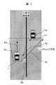
次に、自車1の進行方向変更予定の意図を汲んで、安全確保領域を隣のレーンに延ばす例を、図7を用いて説明する。図7では、自車1が右方向72のレーンに移動する場合である。ここで自車1の進路73は左のレーンであり、右前方に他車74が存在するため、本来の他車に対する安全確保領域は、前述したように、右方向に伸びた安全確保領域75である。しかしながら、自車1が右方向に移ろうとする意図があるため、更に右方向に伸ばした安全確保領域76を設定する。安全確保領域77の上底の延伸長は、右レーンの長さとする、或いはある定数とする。このときの右角度θ2(78)の角度は式5とする。 Next, an example of extending the safety ensuring area to the adjacent lane based on the intention of changing the traveling direction of the
θ2=atn[上底右半分の延伸長/安全確保領域の長さ] …式5
このように、レーンを移る意図がある場合に、自車1の安全確保領域を隣のレーンまで延ばすことにより、現在では減速判定外となるレーンの車に対しても回避行動を行うことが可能となる。θ2 = atn [extension length of upper right bottom half / length of safety ensuring area]
Thus, when there is an intention to move lanes, it is possible to perform avoidance actions even for vehicles in lanes that are currently out of deceleration judgment by extending the safety ensuring area of the
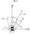
次に、交差点を右折する場合の安全確保領域の延伸方法を、図8の例で説明する。図8では、自車1は右折行動に入る前であるため、自車1の進行方向82は前方のままとなっているが、方向指示器または設定経路に基づくナビゲーション装置の情報、またはハンドル角を取得することにより、右折行動83の方向に進むことが判ったとする。このとき、歩行者84に対して安全確保領域85を横断歩道86まで延ばす。ここでは、安全確保領域の右半分の延伸長として、前述した歩行者の方向のみならず、右折して横切る車線幅をも加える。また無条件に、横断歩道まで伸ばしても良い。左折の場合にも同様に行えば良い。 Next, a method for extending the safety ensuring area when turning right at the intersection will be described with reference to the example of FIG. In FIG. 8, since the
また、左カーブや右カーブを曲がる時には、安全確保領域は前方の道路形状、即ちカーブ形状に合わせて変形させても良い。 Further, when turning a left curve or a right curve, the safety ensuring area may be deformed according to the road shape ahead, that is, the curve shape.
次に、自車がハンドルを切った場合の安全確保領域の設定方法について図9の例を用いて説明する。図9では、ハンドルを切っているが、自車1の進行方向が未だ変っていない状況を示す。しかしながらハンドルを切ったためいずれハンドル角に応じた角度φ(92)の方向93に進行方向が変化する。この場合には、現在の安全確保領域94を、φ回転させた安全確保領域95に変更させる。 Next, a method for setting a safety ensuring area when the vehicle has turned the steering wheel will be described with reference to the example of FIG. FIG. 9 shows a situation where the steering wheel is turned but the traveling direction of the
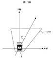
また、図10に示すように、ハンドルを切った場合には、安全確保領域を回転させずに、ハンドルを切った方向に伸ばした安全確保領域1001としても良い。この場合の右半分上底延伸長としては、式6としても良い。 Further, as shown in FIG. 10, when the handle is cut, the
右半分上底延伸長=sinφ×安全確保領域の長さ …式6
次に、他車安全確保領域進入判定部107について説明する。安全確保領域進入判定部は、安全確保領域延伸計算部106で計算した、他の対象物それぞれに設定した安全確保領域に、対象物が進入しているかまたは、進入すると予測されるかを判定する。すなわち、安全確保領域への他移動体の進入の有無を判定するものである。対象物が進入しているかまたは、進入すると予測される場合には、自車の減速度・速度・ハンドル設定部108にて減速度またはハンドル角速度を設定する。Right half top bottom extension length = sinφ x safety area length
Next, the other vehicle safety ensuring area
進入予測方法について図11を用いて説明する。図11の例では、他車1101の相対速度ベクトルにT秒をかけて、T秒後の他車の位置1102を計算する。次に、他車の現在位置とT秒後の他車の位置の間にエンベロップ1103と1104を引く。次に、他車と他車のT秒後の位置およびその間のエンベロップが、安全確保領域1105に入っているならば、進入すると判定する。ここで、他車の将来の軌跡と安全確保領域1105とが交わるかどうかによって判定しても良い。図11の例では進入予定と判定される。ここでTの設定方法としては、自車1が急減速をかけた場合に完全に停止する秒数、即ち式7としても良い。 The approach prediction method will be described with reference to FIG. In the example of FIG. 11, the relative speed vector of the
T=自車の絶対速度の二乗/(2×急減速度最大値) …式7
ここで、急減速最大値の一例として0.2G(Gは重力加速度) として、予めこの値を設定しておく。T = the square of the absolute speed of the vehicle / (2 × maximum sudden deceleration)
Here, as an example of the maximum sudden deceleration value, this value is set in advance as 0.2 G (G is gravitational acceleration).
以上の判定を対象物全てについて行う。 The above determination is performed for all the objects.
次に、自車の減速度・速度・ハンドル設定部108について説明する。各々の対象物毎が安全確保領域に進入した場合の減速度とハンドル角の設定方法について、図12の例で説明する。まず、安全確保領域1201について、T秒後に他車が進入すると判定された場合に、T秒後の他車1202とのy方向の相対距離と、y軸方向(自車の進行方向)の相対速度に応じた減速度、および自車1と他車の重なり率であるオフセット率の補正にて減速度を設定する式8の方法がある。 Next, the deceleration / speed /
減速度=y方向の相対速度の二乗/(2×y方向の相対距離)×オフセット率…式8
ここでオフセット率の計算方法として、自車1と他車の重なり長であるD1203と自車の幅W1204の比、即ちD/Wとする方法や、(D+δ)/Wとする方法(δは自車のドア幅と他車のドア幅)、安全確保領域に他車が進入した長さと安全確保領域の横方向の長さとする方法がある。またDは負の値も取るものとする。ここで、オフセット率に
(D+δ)/Wとした場合には、車のドアが急に開いて接触事故となるリスクを防ぐ効果がある。ここで、減速度とオフセット率の計算として、T秒後の対象物でなくとも、現在地点の対象物の位置を元に計算しても良い。またオフセット率が0以下の場合には、再度オフセット率を0と設定しても良い。Deceleration = square of relative velocity in y direction / (2 × relative distance in y direction) × offset rate ...
Here, as a calculation method of the offset rate, the ratio of D1203 which is the overlap length of the
また、この場合にはハンドル操舵による回避もありえる。この方法について述べる。ここで、T秒後に安全確保領域が他車にかからないようにすれば良いため、安全確保領域の回転を行う。この例を図13で説明する。図13では、T秒後の他車131が安全確保領域132に進入する。ここで、安全確保領域に他車が入るため、安全確保領域を回転させ、他車が安全確保領域に入らないように回転角φ133を決定する。ここでの回転後の安全確保領域が134となる。またここで、ハンドル角速度をφ/Tとする。 In this case, avoidance by steering the steering wheel may be possible. This method will be described. Here, since it is sufficient that the safety ensuring area does not cover other vehicles after T seconds, the safety ensuring area is rotated. This example will be described with reference to FIG. In FIG. 13, the
次に、この操作を、検出した全ての対象物について行い、減速度の最も大きいものを選択する。ハンドル角速度については、急ハンドルとなると車体が不安定になり危険となるため、ハンドル角速度の絶対値の少ない方を選択する。 Next, this operation is performed on all detected objects, and the object with the largest deceleration is selected. As for the steering wheel angular velocity, if the steering wheel is sharp, the vehicle body becomes unstable and dangerous. Therefore, the steering wheel angular velocity having the smaller absolute value is selected.
この例を、すり抜けの場合を元に図14の例で説明する。ここで、他車が2台141,142で同じ進行方向を向いて走行している例である。ここでの他車141に対する安全確保領域が143,他車142に対する安全確保領域が144とする。前述したように、オフセット率を計算し減速度を計算した結果、他車141に対する減速度が0.1G(Gは重力加速度) 、他車142に対する減速度が0.2G の場合には、減速度の大きい方を採用し、自車の減速度を0.2Gとする。 This example will be described with reference to the example of FIG. Here, it is an example in which other vehicles are traveling with the two
最後に、速度・ハンドル制御部109について説明する。速度・ハンドル制御部は、自車の減速度・速度・ハンドル設定部108で設定した減速度、若しくは減速度より計算した速度の時系列、及びハンドル角速度、またはハンドル角速度から計算したハンドル角の時系列を車内に設置されているハンドルやブレーキコントローラECU(Electronic
Control Unit)へ送り、この情報を元に車両の制御を行う。Finally, the speed /
Control unit) and control the vehicle based on this information.
次に、本システムの全体の処理の概要の流れを、図15に示すシーケンス図を用いて説明する。本システムは車のイグニッションをオンにした後からオフにする間まで作動する。イグニッションをオンにし本システムが稼動した後、ステップ151にて時々刻々自車の位置を取得し、ステップ152にて自車両近傍のマップを作成し、ステップ153にて他の対象物(他車と歩行者)を計測する。このステップ151は、図1の自車の位置,速度,進行方向取得部104に相当し、ステップ152は、図1の自車前方道路形状取得部105に、ステップ153は図1の物体認識部103に相当する。 Next, the outline of the overall processing of this system will be described with reference to the sequence diagram shown in FIG. The system works after turning on the vehicle's ignition until turning it off. After the system is operated with the ignition turned on, the position of the host vehicle is obtained from time to time in
次に、自車のハンドル角速度と減速度の初期値を0とする。計測した他の対象物の数をN個に対してそれぞれ、ステップ154にて安全確保領域を設定し、ステップ155にて対象物が安全確保領域にあるまたは入ると予測されるかどうかを判断し、安全確保領域にあるまたは入ると予測される場合には、ステップ156にて減速またはハンドル角速度の操作量を決定する。ステップ157にてその減速度またはハンドル角速度が最大値であるならば、回避目標値として更新を行う。ここで、ステップ154は、図1の安全確保領域延伸計算部106に、ステップ155は、図1の他車安全確保領域進入判定部107に、ステップ156,ステップ157は図1の自車の減速度・速度・ハンドル設定部108に相当する。 Next, the initial values of the steering wheel angular velocity and deceleration of the vehicle are set to zero. For each of N measured objects, a safety ensuring area is set in
このステップ154から158までの動作を対象物の数だけ実行後、決定された減速度とハンドル角速度を車両コントローラに送り、ステップ159にて車両のコントロールを行う。ステップ159は、図1の速度・ハンドル制御部109に相当する。 After executing the operations from
次に、本システムのドライバへの情報提示方法について記す。ドライバへの提示方法には、画面とシステムが回避行動をする前に警報を行う。画面は、ヘッドアップディスプレイまたはナビの画面に図2のマップを表示させ、安全確保領域に近づく移動体に対しては、その移動体を強調させ表示する。ここで、各移動体の安全確保領域を表示しても良い。また警報としては、画面をフラッシュさせるまたはビープ音を鳴らしても良い。 Next, a method for presenting information to the driver of this system will be described. In the presentation method to the driver, an alarm is given before the screen and the system perform an avoidance action. The screen displays the map of FIG. 2 on the head-up display or the navigation screen, and highlights and displays the moving body approaching the safety ensuring area. Here, you may display the safety ensuring area | region of each mobile body. As an alarm, the screen may be flashed or a beep sound may be generated.
次に、本実施形態の安全確保領域の高さ方向への拡張について図16を用いて説明する。高さ方向として車高と車高のマージン分を図4の安全確保領域の鉛直方向に伸ばす。そして、図1の自車前方道路形状取得部105にて、前方道路の陸橋1602の高さを計算する。前方道路の陸橋1602の高さと、自車1の安全確保領域1601の高さ方向のオフセット率を求め、その高さ方向のオフセット率を式8の減速度にかけることで対応する。ここでのオフセット率として、{陸橋の高さ−(自車の高さ+δ)}/自車の高さとする方法がある。δは自車の上下方向の振動によるぶれを示す値であり、予め設定しておく。尚、バンプ1603についても同様にして、自車1の下部におけるオフセット率を求める。他車安全確保領域進入判定部107では、このオフセット率に応じて自車1の減速度を決める。オフセット率が正の値でもし陸橋を潜れないようであれば、その前に自車1が停止するような減速度になるように信号を出力する。オフセット率が負の値で潜ることは可能だが、ぎりぎりの場合に道路状況によっては自車1が陸橋1602に接触する可能性がある場合には、自車1が陸橋1602に達する前に例えば徐行速度まで自車速度を低下させるような減速度になるように信号を出力する。オフセット率が負で十分に余裕がある場合には、減速させない。バンプの場合も同様だが、バンプの場合はオフセット率よりも、バンプの存在自体で事前に徐行速度(またはバウンドして車両下部がバンプに接触しないような速度)まで低下するような減速度信号を出力しても良い。 Next, expansion of the safety ensuring area in the height direction according to the present embodiment will be described with reference to FIG. As the height direction, the vehicle height and the margin of the vehicle height are extended in the vertical direction of the safety ensuring region in FIG. Then, the own vehicle forward road
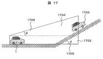
次に、坂道がある場合での、本実施形態の安全確保領域の高さ方向への拡張について図17を用いて説明する。平地においては、高さ方向の安全確保領域は長方形とすることが好ましいが、上り坂に差し掛かる場合には、安全確保領域を長方形とすると、前方の上り坂を走行中の車両が安全確保領域から外れることになる。このため、安全確保領域を前方の上り坂の勾配に応じて台形に変形することが好ましい。図17において、自車1は平地を走行しており、高さ方向の安全確保領域1702を長方形(図の点線)に設定した場合、先行車両1703は、実際は何らかの減速度を発生させるに十分な距離であっても、安全確保領域1702が先行車両1703を捕らえていないため、減速度が発生しない。そこで、安全確保領域1702を、自車1の走行している道路の勾配と、前方の道路の勾配との差によって、台形1704に変形させる。ここでの台形の変形は、勾配差θ1705の値と符号に従い、符号が正の場合(前方が上り坂)上方の角度を1706とし、上方に変形させる。符号が負の場合(前方が下り坂)下方に変形させる。ここでのφは、θの値と一致させても良い。また、前方の勾配と、自車の勾配はナビの地図情報から得ることが可能である。 Next, the extension in the height direction of the safety ensuring area of this embodiment when there is a slope will be described with reference to FIG. On flat ground, it is preferable that the safety area in the height direction is a rectangle, but if it is going uphill, if the safety area is a rectangle, the vehicle traveling on the uphill ahead is the safety area. It will come off. For this reason, it is preferable to deform the safety ensuring area into a trapezoid according to the slope of the uphill ahead. In FIG. 17, the
次に、本実施形態で、後方を走行する他車からの追突の可能性がある場合の対応について述べる。自車の後方に存在する車で、相対速度が正の場合には、安全確保領域を後方に設定し、後方の車が安全確保領域に入るかどうかで追突の可能性を判断する。自車に追突の可能性がある場合には、式8の減速度をマイナス、即ち加速として対応させる。 Next, in the present embodiment, a description will be given of a case where there is a possibility of a rear-end collision from another vehicle traveling behind. When the vehicle is behind the host vehicle and the relative speed is positive, the safety ensuring area is set to the rear, and the possibility of a rear-end collision is determined based on whether the rear vehicle enters the safety ensuring area. When there is a possibility of a rear-end collision in the own vehicle, the deceleration of
次に、自車が走行している時の勾配を取得し、勾配が負、即ち坂道を下っているならば安全確保領域を進行方向に伸ばし、坂道を登っているならば安全確保領域を進行方向に縮めることで勾配による影響を吸収させる方法について述べる。この対応方法の一つとして、式2の自車の安全確保領域の長さとして、自車の最大減速度に勾配による重力加速度を足すことで対応させる。自車の勾配を取得する方法としては、加速度センサを用いる方法や、GPS(Global Positioning System) で知り得た自分の位置により地図を参照し、地図に記録されている位置ごとの勾配情報を取得しても良い。 Next, obtain the gradient when the vehicle is traveling, and if the gradient is negative, that is, if it is downhill, extend the safety area in the direction of travel, if it is climbing up the slope, advance the safety area A method for absorbing the influence of the gradient by shrinking in the direction will be described. As one of the countermeasures, the length of the safety ensuring area of the own vehicle of
次に、移動物体を運転する者の減速傾向,反応時間,疲労度計測結果により、運転者の減速が強い傾向にある場合、反応時間が遅い傾向にある場合、または運転者が疲労している場合の少なくともいずれか一方が該当する場合では、安全確保領域を通常、すなわちこれらが該当しない場合よりも大きくさせ、自動で回避する場合にドライバとの感覚ずれを少なくさせる方法について述べる。この場合には、減速傾向が強いドライバ,反応時間が遅いドライバ,疲労の激しいドライバに対して式2で示される安全確保領域の長さにマージンをかける。このマージンとしては、予め設定した減速傾向のパラメータ、反応時間、疲労度に応じたテーブルを参照する。減速傾向の取得としては、「谷越ほか:車両情報を活用したテレマティクス安全運転支援への取り組み,日立評論,Vol.88,No.08,
pp.22−25,2005年8月」の加速度の標準偏差と歪度使用し、これらの加速度標準偏差と歪度を車両情報から計算する方法がある。反応時間に関しては、アクセルを離してからブレーキを踏むまでの時間を車両情報から取得し、この傾向を予め統計的に保持しておけば良い。疲労度の計測としては、ステアリングのぶれを計測する方法,唾液を用いた生体情報を用いる方法がある。Next, the driver's deceleration tendency, reaction time, and fatigue level measurement results indicate that the driver's deceleration tends to be strong, the reaction time tends to be slow, or the driver is tired In the case where at least one of the cases is applicable, a method for reducing the sense difference with the driver when the safety ensuring area is made larger than usual, that is, when these are not applicable, and automatically avoiding will be described. In this case, a margin is applied to the length of the safety ensuring area represented by
pp. 22-25, August 2005 "is used, and the acceleration standard deviation and the skewness are calculated from the vehicle information. Regarding the reaction time, the time from when the accelerator is released to when the brake is depressed is acquired from the vehicle information, and this tendency may be statistically held in advance. As the measurement of the degree of fatigue, there are a method of measuring steering shake and a method of using biological information using saliva.
次に、他の対象物が自車にどれだけ接近するかの緊急度に応じて減速度を設定する方法について述べる。この方法として、複数の相似の安全確保領域を持ち、どの安全確保領域に入ったかで減速度を決め、その安全確保領域に設定しておいた緊急度合いに対応した減速度係数を式8にかけることで対応できる。この緊急度合いに応じた減速度係数は予め設定しておく。 Next, a method for setting the deceleration according to the degree of urgency of how close the other object is to the own vehicle will be described. As this method, there are a plurality of similar safety ensuring areas, the deceleration is determined according to which safety ensuring area is entered, and the deceleration coefficient corresponding to the degree of emergency set in the safety ensuring area is applied to
また、インフラ通信、または移動体同士の通信により、自移動体から検出できない移動物体を知る、または自移動体からはブラインドになっている領域に安全確保領域を設定することも可能である。 It is also possible to know a moving object that cannot be detected from the mobile body by infrastructure communication or communication between mobile bodies, or to set a safety ensuring area in an area that is blind from the mobile body.
以上、本発明の実施形態について説明してきたが、従来の技術、例えば自移動体に安全確保領域を一つ設定する方式では、例えば自移動体から横方向に遠ざかる他移動体が安全確保領域内に存在すれば、当該他移動体が自移動体に接近していなくても、自移動体を減速させる制御を行っていた。 As described above, the embodiments of the present invention have been described. However, in the conventional technique, for example, a method in which one safety ensuring area is set in the own moving body, for example, another moving body moving away from the own moving body in the lateral direction is within the safety ensuring area. If the other moving body is not close to the own moving body, control for decelerating the own moving body is performed.
また、他移動体それぞれに安全確保領域を設定する方法によれば、自移動体の進路方向に対して遠ざかる他移動体に対しては無駄な減速が行われないが、他移動体の今後の進路予定を自移動体が知り得ることが困難なため、他移動体の進路予定方向に沿って安全確保領域を変形させることが困難であった。 In addition, according to the method of setting the safety ensuring area for each of the other moving bodies, useless deceleration is not performed for the other moving bodies moving away from the traveling direction of the own moving body. Since it is difficult for the own mobile body to know the course plan, it is difficult to deform the safety ensuring area along the planned course direction of the other mobile body.
また、自移動体の進路変更予定を他移動体が持つ安全確保領域に反映させることが困難であったため、安全確保領域を設定した後に、別途自車の進行予定方向を反映させるロジック判定が必要となり、計算量の観点から好ましくなかった。 In addition, since it was difficult to reflect the route change schedule of the own mobile body in the safety assurance area of other mobile bodies, it is necessary to make a logic decision to reflect the direction of travel of the vehicle separately after setting the safety assurance area. This is not preferable from the viewpoint of calculation amount.
また、安全確保領域を自移動体の進路の道路形状に変形する方法は、衝突回避の際に自移動体の進路変更意図を考慮していないため、進路変更の際の回避行動が困難であった。 In addition, the method of transforming the safety ensuring area into the road shape of the path of the moving body does not consider the intention of changing the path of the moving body when avoiding a collision, and therefore it is difficult to avoid the movement when changing the path. It was.
上記実施形態は、これらの課題のいずれかを克服するものであり、カメラやレーダにより他の移動物体を検出する手段と、検出された他の移動物体それぞれに対して安全確保領域を自移動体に複数(検出された移動物体の数)設定し、それぞれの安全確保領域を自移動体の進行方向に相対速度の大きさに応じて延伸するのみならず、検出した移動物体の方向に対しても伸ばす手段と、自移動体が進路変更を行う予定の意図を取得する手段、自移動体が今後進む方向へ安全確保領域を伸ばす手段、それぞれの安全確保領域に他の移動物体が進入するかを判定する手段と、前記判定手段により他の移動物体が安全確保領域に進入すると判定した場合、回避する操作量を決定する手段と、前述した操作量に基づき自移動体の制御または警報を行う手段を有する。 The above embodiment overcomes any of these problems, and means for detecting other moving objects by a camera or radar, and a safety ensuring area for each of the detected other moving objects. Multiple (number of detected moving objects), and each safety ensuring area is not only extended in the traveling direction of the moving body according to the magnitude of the relative speed, but also in the direction of the detected moving object A means for extending the length of the vehicle, a means for acquiring the intention that the mobile body will change the course, a means for extending the safe area in the direction in which the mobile body will advance, and whether other moving objects enter the respective safety areas And a means for determining an operation amount to be avoided when the determination means determines that another moving object enters the safety ensuring area, and controls or warns the moving body based on the operation amount described above. hand Having.
本構成により、他の移動物体それぞれに対して自移動体に安全確保領域を設定することにより、自移動体から遠ざかる移動物体に対して回避を行わないようにした。また、自移動体の進路変更の意図を直接安全確保領域に反映させることとした。 With this configuration, by setting a safety ensuring area in the own moving body for each of the other moving objects, the avoidance is not performed for the moving object moving away from the own moving body. In addition, the intention to change the course of the moving body is directly reflected in the safety ensuring area.
この実施形態によれば、自移動体が進路変更を行う予定の意図を取得し、自移動体が意図する進路変更方向へ安全確保領域を伸ばすことにより、例えば車の場合には、隣のレーンの車を回避対象とするため、レーンチェンジに対応可能となる。また、自移動体の進行方向の意図を直接安全確保領域に反映させることが可能となり、別判定のドライバ意図ロジックが不必要となり、計算量を抑えることが可能となる。 According to this embodiment, by acquiring the intention that the mobile unit intends to change the course and extending the safety ensuring area in the course change direction intended by the mobile unit, for example, in the case of a car, the adjacent lane Because this car is targeted for avoidance, it becomes possible to respond to lane changes. In addition, it is possible to directly reflect the intention of the moving body in the traveling direction directly in the safety ensuring area, so that the driver intention logic for another determination is unnecessary, and the calculation amount can be suppressed.
更には、検出した移動物体の方向へも安全確保領域を伸ばすため、隣を並走する移動体間のすり抜けに対しても回避が行えるなどの効果も得られる。 Furthermore, since the safety ensuring area is extended in the direction of the detected moving object, it is possible to obtain an effect that it is possible to avoid slipping between moving objects running side by side.
1 自車
101 レーダ
102 カメラ
103 物体認識部
104 自車の位置,速度,進行方向取得部
105 自車前方道路形状取得部
106 安全確保領域延伸計算部
107 他車安全確保領域進入判定部
108 自車の減速度・速度・ハンドル設定部
109 速度・ハンドル制御部
110 出力部DESCRIPTION OF
Claims (36)
Translated fromJapanese前記入力部で入力した前記対象物の前記相対物理量に応じて前記自移動体の周囲の仮想的な安全確保領域を決定する安全確保領域決定部と、
安全確保領域決定部で決定した前記安全確保領域への前記他移動体の進入の有無を判定する他移動体進入判定部と、
前記他移動体進入判定部で前記安全確保領域に前記他移動体が進入すると判定した場合に、回避制御または警報を行うための信号を出力する出力部と、
を有する衝突回避装置。An input unit for inputting a relative physical quantity between at least one of the other moving object, the feature, the point, the terrain, and the area information existing around the moving object and the moving object;
A safety ensuring area determining unit that determines a virtual safety ensuring area around the mobile body according to the relative physical quantity of the object input by the input unit;
An other moving body entry determination unit that determines whether or not the other moving body has entered the safety ensuring area determined by the safety ensuring area determination unit;
An output unit that outputs a signal for performing avoidance control or warning when the other moving body approach determination unit determines that the other moving body enters the safety ensuring area;
A collision avoidance device.
自移動体周囲に存在する他移動体,地物,地点,地形の少なくともいずれか一つの対象物と前記自移動体との間の前記相対物理量を求める相対物理量演算部を有し、
前記入力部は、前記相対物理量演算部で求めた前記相対物理量を入力する衝突回避装置。The collision avoidance device according to claim 1,
A relative physical quantity calculation unit that obtains the relative physical quantity between at least one of a moving object, a feature, a point, and a terrain existing around the moving object and the moving object;
The input unit is a collision avoidance device that inputs the relative physical quantity obtained by the relative physical quantity calculation unit.
前記相対物理量演算部は、レーダまたはカメラによる物体認識部からの信号に基づいて前記対象物の前記相対物理量を求める衝突回避装置。The collision avoidance device according to claim 2,
The relative physical quantity calculation unit is a collision avoidance device that calculates the relative physical quantity of the object based on a signal from an object recognition unit by a radar or a camera.
前記相対物理量演算部は、ナビゲーション装置からの信号に基づいて地図上の前記自移動体の位置,速度,進行方向を求める衝突回避装置。The collision avoidance device according to claim 2,
The relative physical quantity calculation unit is a collision avoidance device that obtains the position, speed, and traveling direction of the moving body on a map based on a signal from a navigation device.
前記相対物理量演算部は、方向指示器からの信号,操舵角センサからの信号,設定経路に基づくナビゲーション装置からの信号の少なくともいずれか一つに基づいて自移動体の進行方向を求める衝突回避装置。The collision avoidance device according to claim 2,
The relative physical quantity calculation unit is a collision avoidance device that obtains the traveling direction of the vehicle based on at least one of a signal from a direction indicator, a signal from a steering angle sensor, and a signal from a navigation device based on a set route. .
安全確保領域決定部は、前記入力部で入力した前記対象物の前記相対物理量に応じて前記自移動体の周囲の仮想的な安全確保領域の大きさを変化させる衝突回避装置。The collision avoidance device according to claim 1,
The safety ensuring area determining unit is a collision avoidance device that changes the size of a virtual safety ensuring area around the mobile body according to the relative physical quantity of the object input by the input unit.
前記安全確保領域決定部は、前記入力部で前記相対物理量を入力した前記各対象物に対してそれぞれ前記自移動体の周囲の仮想的な安全確保領域を決定する衝突回避装置。The collision avoidance device according to claim 1,
The said safety ensuring area | region determination part is a collision avoidance apparatus which determines the virtual safety ensuring area | region around the said mobile body with respect to each said object which input the said relative physical quantity with the said input part, respectively.
前記安全確保領域決定部は、前記自移動体から離れるにつれて前記安全確保領域の幅を広く設定する衝突回避装置。The collision avoidance device according to claim 1,
The said safety ensuring area | region determination part is a collision avoidance apparatus which sets the width | variety of the said safety ensuring area | region widely as it leaves | separates from the said mobile body.
前記自移動体は側方にドアを有し、前記安全確保領域決定部は、前記安全確保領域の最短幅を前記自移動体が当該ドアを開いたときの横方向幅に設定する衝突回避装置。The collision avoidance device according to claim 8,
The self-moving body has a door on a side, and the safety ensuring area determination unit sets a shortest width of the safety ensuring area to a lateral width when the self-moving body opens the door. .
前記安全確保領域決定部は、運転者の操舵傾向に応じて前記安全確保領域の幅を設定する衝突回避装置。The collision avoidance device according to claim 8,
The said safety ensuring area | region determination part is a collision avoidance apparatus which sets the width | variety of the said safety ensuring area | region according to a driver | operator's steering tendency.
前記安全確保領域決定部は、所定の条件で前記安全確保領域の幅を広げる場合に、前記自移動体の絶対速度が小さい場合にはより広く、前記自移動体の絶対速度が大きい場合にはより狭く広げる衝突回避装置。The collision avoidance device according to claim 1,
When the width of the safety ensuring area is increased under a predetermined condition, the safety ensuring area determining unit is wider when the absolute speed of the mobile body is small, and when the absolute speed of the mobile body is large. Narrower collision avoidance device.
前記安全確保領域決定部は、前記自移動体の絶対速度または前記対象物との相対速度の少なくともいずれか一方によって前記安全確保領域の進行方向長さを設定する衝突回避装置。The collision avoidance device according to claim 1,
The said safety ensuring area | region determination part is a collision avoidance apparatus which sets the advancing direction length of the said safety ensuring area | region by at least any one of the absolute speed of the said mobile body, or the relative speed with the said target object.
前記安全確保領域決定部は、さらに前記自移動体の空走時間及び最大減速度に基づいて前記安全確保領域の進行方向長さを設定する衝突回避装置。The collision avoidance device according to claim 12,
The said safety ensuring area | region determination part is a collision avoidance apparatus which sets the advancing direction length of the said safety ensuring area | region further based on the idle time and the maximum deceleration of the said mobile body further.
前記安全確保領域決定部は、前記最大減速度を0.2G として前記安全確保領域の進行方向長さを設定する衝突回避装置。The collision avoidance device according to claim 13,
The said safety ensuring area | region determination part is a collision avoidance apparatus which sets the advancing direction length of the said safety ensuring area | region as said maximum deceleration 0.2G.
前記安全確保領域決定部は、前記自移動体から離れる前記対象物に対しては前記安全確保領域を設定しない衝突回避装置。The collision avoidance device according to claim 1,
The said safety ensuring area | region determination part is a collision avoidance apparatus which does not set the said safety ensuring area | region with respect to the said object which leaves | separates from the said mobile body.
前記安全確保領域決定部は、前記自移動体から離れる前記対象物に対しては前記安全確保領域を最小単位に設定する衝突回避装置。The collision avoidance device according to claim 1,
The said safety ensuring area | region determination part is a collision avoidance apparatus which sets the said safety ensuring area | region to the minimum unit with respect to the said object which leaves | separates from the said mobile body.
前記出力部は、前記自移動体から離れる前記対象物に対しては回避制御または警報を行うための信号を出力しない衝突回避装置。The collision avoidance device according to claim 1,
The said output part is a collision avoidance apparatus which does not output the signal for performing avoidance control or warning with respect to the said target object which leaves | separates from the said mobile body.
前記安全確保領域決定部は、前記対象物との横方向相対速度に基づいて、前記自移動体に対して前記対象物が存在する側の前記安全確保領域の幅を設定する衝突回避装置。The collision avoidance device according to claim 1,
The said safety ensuring area | region determination part is a collision avoidance apparatus which sets the width | variety of the said safety ensuring area | region of the side in which the said object exists with respect to the said mobile body based on the horizontal direction relative speed with the said object.
前記安全確保領域決定部は、前記自移動体が所定の走行レーンに移る場合、当該走行レーンが存在する側の前記安全確保領域の幅を増加させる衝突回避装置。The collision avoidance device according to claim 1,
The said safety ensuring area | region determination part is a collision avoidance apparatus which increases the width | variety of the said safety ensuring area | region on the side in which the said driving lane exists, when the said mobile body moves to a predetermined driving lane.
前記安全確保領域決定部は、方向指示器からの信号,操舵角センサからの信号,設定経路に基づくナビゲーション装置からの信号の少なくともいずれか一つに基づいて前記自移動体の進行方向を判定し、当該進行方向側の前記安全確保領域の幅を増加させる衝突回避装置。The collision avoidance device according to claim 1,
The safety ensuring area determining unit determines a traveling direction of the mobile body based on at least one of a signal from a direction indicator, a signal from a steering angle sensor, and a signal from a navigation device based on a set route. The collision avoidance device that increases the width of the safety ensuring area on the traveling direction side.
前記安全確保領域決定部は、前記自移動体が交差点を曲がり、進行方向に存在する横断歩道を横切る場合には、当該横断歩道を含むように前記安全確保領域を拡大する衝突回避装置。The collision avoidance device according to claim 20,
The said safety ensuring area | region determination part is a collision avoidance apparatus which expands the said safety ensuring area | region so that the said pedestrian crossing may be included when the said mobile body turns the intersection and crosses the pedestrian crossing which exists in the advancing direction.
前記安全確保領域決定部は、自移動体がカーブ路を進行中の場合には、当該カーブ路の形状に合わせて前記安全確保領域を変形する衝突回避装置。The collision avoidance device according to claim 1,
The said safety ensuring area | region determination part is a collision avoidance apparatus which deform | transforms the said safety ensuring area | region according to the shape of the said curved road, when the self-moving body is advancing on the curved road.
前記安全確保領域決定部は、操舵角に応じて前記安全確保領域を操舵側に回転させる衝突回避装置。The collision avoidance device according to claim 1,
The safety ensuring area determining unit is a collision avoidance device that rotates the safety ensuring area to the steering side according to a steering angle.
前記安全確保領域決定部は、操舵角に応じて前記安全確保領域を操舵側に拡大する衝突回避装置。The collision avoidance device according to claim 1,
The safety ensuring area determination unit is a collision avoidance device that expands the safety ensuring area to the steering side according to a steering angle.
前記他移動体進入判定部は、前記他移動体の将来の軌跡を予測し、当該軌跡が前記安全確保領域と交わる場合に前記安全確保領域へ前記他移動体が進入すると判定する衝突回避装置。The collision avoidance device according to claim 1,
The said other mobile body approach determination part is a collision avoidance apparatus which estimates the future locus | trajectory of the said other mobile body, and determines that the said other mobile body approachs into the said safety ensuring area | region when the said locus | trajectory crosses the said safety ensuring area | region.
前記出力部は、前記他移動体進入判定部で前記安全確保領域に前記他移動体が進入すると判定した場合に、前記他移動体が進入する時点における前記他移動体との相対速度,相対距離、およびオフセット率に基づいて求められる前記自移動体の減速度を出力する衝突回避装置。The collision avoidance device according to claim 1,
The output unit determines a relative speed and a relative distance with the other moving body at the time when the other moving body enters when the other moving body entering determination unit determines that the other moving body enters the safety ensuring area. , And a collision avoidance device that outputs the deceleration of the mobile body obtained based on the offset rate.
前記出力部は、前記他移動体毎に求めた前記減速度のうち一番大きな減速度を選択して出力する衝突回避装置。The collision avoidance device according to claim 26, wherein
The said output part is a collision avoidance apparatus which selects and outputs the largest deceleration among the said deceleration calculated | required for every said other moving body.
前記出力部は、前記他移動体進入判定部で前記安全確保領域に前記他移動体が進入すると判定した場合に、前記安全確保領域を操舵によって回転させることによって、前記他移動体が進入する時点の前記他移動体が前記安全確保領域から外れるように求めた前記操舵の角度指令信号を出力する衝突回避装置。The collision avoidance device according to claim 1,
When the other moving body approach determination unit determines that the other moving body enters the safety ensuring area, the output unit rotates the safety ensuring area by steering, and the other moving body enters. A collision avoidance device that outputs the steering angle command signal that is determined so that the other moving body deviates from the safety ensuring area.
前記出力部は、前記他移動体毎に求めた前記角度指令信号のうち一番小さな角度指令信号を選択して出力する衝突回避装置。The collision avoidance device according to claim 28,
The said output part is a collision avoidance apparatus which selects and outputs the smallest angle command signal among the said angle command signals calculated | required for every said other moving body.
前記出力部は、前記安全確保領域,前記安全確保領域に進入している他移動体、または前記安全確保領域に進入が予測される他移動体の少なくともいずれか一方を画面に表示するための信号を出力する衝突回避装置。The collision avoidance device according to claim 1,
The output unit is a signal for displaying on the screen at least one of the safety ensuring area, another moving body entering the safety ensuring area, or another moving body predicted to enter the safety ensuring area. A collision avoidance device that outputs.
前記安全確保領域決定部は、前記入力部で入力した前記対象物の前記相対物理量に応じて前記自移動体の高さ方向の仮想的な安全確保領域を決定する衝突回避装置。The collision avoidance device according to claim 1,
The said safety ensuring area | region determination part is a collision avoidance apparatus which determines the virtual safety ensuring area | region of the height direction of the said mobile body according to the said relative physical quantity of the said target object input with the said input part.
前記安全確保領域決定部は、自移動体の後方に存在する他移動体の相対速度が正の場合に、前記安全確保領域を自移動体の後方に伸ばし、
前記出力部は、前記他移動体進入判定部で前記安全確保領域に前記他移動体が進入すると判定した場合に、前記自移動体を加速する加速信号を出力する衝突回避装置。The collision avoidance device according to claim 1,
The safety ensuring area determining unit extends the safety ensuring area to the rear of the mobile body when the relative speed of the other mobile body existing behind the mobile body is positive,
The said output part is a collision avoidance apparatus which outputs the acceleration signal which accelerates the said mobile body, when it determines with the said other mobile body approaching into the said safety ensuring area | region by the said other mobile body approach determination part.
前記安全確保領域決定部は、前記自移動体が下り勾配を走行中の場合は前記安全確保領域を進行方向に伸ばし、上り勾配を走行中の場合は前記安全確保領域を進行方向に縮める衝突回避装置。The collision avoidance device according to claim 1,
The safety ensuring area determining unit extends the safety ensuring area in a traveling direction when the mobile body is traveling on a downward slope, and avoids a collision by contracting the safety ensuring area in the traveling direction when traveling on an upward slope. apparatus.
前記安全確保領域決定部は、前記自移動体の運転者の減速が強い傾向にある場合、前記運転者の反応時間が遅い傾向にある場合、または前記運転者が疲労している場合の少なくともいずれか一方の場合は、前記安全確保領域を通常よりも大きくする衝突回避装置。The collision avoidance device according to claim 1,
The safety ensuring area determining unit is at least one of a case where the driver of the mobile body tends to decelerate strongly, a case where the driver reaction time tends to be slow, or a case where the driver is tired In either case, the collision avoidance device that makes the safety ensuring area larger than usual.
前記安全確保領域決定部は、インフラ通信または移動体同士の通信により、前記自移動体から検出できない移動物体の情報を得て、当該情報から前記安全確保領域を決定する衝突回避装置。The collision avoidance device according to claim 1,
The said safety ensuring area | region determination part is the collision avoidance apparatus which acquires the information of the moving object which cannot be detected from the said mobile body by infrastructure communication or communication between mobile bodies, and determines the said safety ensuring area | region from the said information.
前記相対物理量に応じて前記自移動体の周囲の仮想的な安全確保領域を決定し、
前記安全確保領域に前記他移動体が進入すると判定した場合に、回避制御を行うまたは警報を出力する衝突回避方法。Input a relative physical quantity between at least one of the other moving objects, features, points, and terrain existing around the moving object and the moving object,
Determine a virtual safety area around the mobile body according to the relative physical quantity,
A collision avoidance method that performs avoidance control or outputs an alarm when it is determined that the other moving body enters the safety ensuring area.
Priority Applications (3)
| Application Number | Priority Date | Filing Date | Title |
|---|---|---|---|
| JP2007078122AJP2008242544A (en) | 2007-03-26 | 2007-03-26 | Collision avoidance apparatus and method |
| US12/015,782US20080243389A1 (en) | 2007-03-26 | 2008-01-17 | Vehicle Collision Avoidance Equipment and Method |
| EP08001189AEP1975903A2 (en) | 2007-03-26 | 2008-01-23 | Vehicle collision avoidance equipment and method |
Applications Claiming Priority (1)
| Application Number | Priority Date | Filing Date | Title |
|---|---|---|---|
| JP2007078122AJP2008242544A (en) | 2007-03-26 | 2007-03-26 | Collision avoidance apparatus and method |
Publications (1)
| Publication Number | Publication Date |
|---|---|
| JP2008242544Atrue JP2008242544A (en) | 2008-10-09 |
Family
ID=39473268
Family Applications (1)
| Application Number | Title | Priority Date | Filing Date |
|---|---|---|---|
| JP2007078122APendingJP2008242544A (en) | 2007-03-26 | 2007-03-26 | Collision avoidance apparatus and method |
Country Status (3)
| Country | Link |
|---|---|
| US (1) | US20080243389A1 (en) |
| EP (1) | EP1975903A2 (en) |
| JP (1) | JP2008242544A (en) |
Cited By (31)
| Publication number | Priority date | Publication date | Assignee | Title |
|---|---|---|---|---|
| JP2010267124A (en)* | 2009-05-15 | 2010-11-25 | Toyota Motor Corp | Environmental prediction device |
| JP2011195083A (en)* | 2010-03-23 | 2011-10-06 | Toyota Motor Corp | Steering assistance device |
| JP2011194507A (en)* | 2010-03-18 | 2011-10-06 | Fujitsu Ltd | Apparatus and program for providing services, and service robot |
| JP2011210102A (en)* | 2010-03-30 | 2011-10-20 | Mazda Motor Corp | Driving support device for vehicle |
| KR20120055458A (en)* | 2010-11-22 | 2012-05-31 | 로베르트 보쉬 게엠베하 | Method of capturing the surroundings of a vehicle |
| CN102632840A (en)* | 2011-02-09 | 2012-08-15 | 本田技研工业株式会社 | Vehicle periphery monitoring apparatus |
| JP2012188029A (en)* | 2011-03-11 | 2012-10-04 | Toyota Motor Corp | Damage reduction braking apparatus and method |
| DE102012103087A1 (en) | 2011-04-11 | 2012-10-11 | Denso Corporation | Object identification device for collision prevention system, has object identification/output unit which identifies object that is present in acquired image by performing selected image processing method, and outputs identification result |
| US8751128B2 (en) | 2009-06-17 | 2014-06-10 | Toyota Jidosha Kabushiki Kaisha | Driving assistance device |
| US8760276B2 (en) | 2010-12-06 | 2014-06-24 | Denso Corporation | Collision detector and warning apparatus which defines an enter-determination area and an exist-determination area |
| CN104709283A (en)* | 2013-12-11 | 2015-06-17 | 现代自动车株式会社 | Lane change control apparatus and control method of the same |
| US9196162B2 (en) | 2011-09-26 | 2015-11-24 | Toyota Jidosha Kabushiki Kaisha | Vehicular driving support system |
| EP3021305A2 (en) | 2014-11-14 | 2016-05-18 | Toyota Jidosha Kabushiki Kaisha | Alerting apparatus |
| KR101714273B1 (en)* | 2015-12-11 | 2017-03-08 | 현대자동차주식회사 | Method and apparatus for controlling path of autonomous driving system |
| JP2017065357A (en)* | 2015-09-29 | 2017-04-06 | 富士重工業株式会社 | Risk degree calculation device |
| WO2017111110A1 (en)* | 2015-12-25 | 2017-06-29 | 株式会社デンソー | Travel support device and travel support method |
| WO2017111135A1 (en)* | 2015-12-25 | 2017-06-29 | 株式会社デンソー | Travel assistance device and travel assistance method |
| WO2017208296A1 (en)* | 2016-05-30 | 2017-12-07 | 日産自動車株式会社 | Object detection method and object detection device |
| JP2018101376A (en)* | 2016-12-22 | 2018-06-28 | 三菱自動車工業株式会社 | Driving support apparatus |
| JP2018122789A (en)* | 2017-02-02 | 2018-08-09 | 株式会社デンソーテン | Driving assist device, driving assist system, and driving assist method |
| KR20190019744A (en)* | 2017-08-18 | 2019-02-27 | 한국철도기술연구원 | System of predicting collision probability for moving vehicles and method of predicting collision for moving vehicles using same |
| JP2019043290A (en)* | 2017-08-31 | 2019-03-22 | トヨタ自動車株式会社 | Vehicle control device |
| JP2019046143A (en)* | 2017-09-01 | 2019-03-22 | 株式会社デンソー | Driving support device |
| WO2019138487A1 (en)* | 2018-01-11 | 2019-07-18 | 住友電気工業株式会社 | Vehicle-mounted device, travel control method, and computer program |
| KR20190102827A (en)* | 2018-02-27 | 2019-09-04 | 주식회사 만도 | Autonomous emergency braking system and method for vehicle at intersection |
| JP2021131902A (en)* | 2020-06-30 | 2021-09-09 | ベイジン バイドゥ ネットコム サイエンス アンド テクノロジー カンパニー リミテッド | Vehicle obstacle avoidance methods, devices, electronic devices and computer storage media |
| JP2021148581A (en)* | 2020-03-18 | 2021-09-27 | 株式会社デンソー | Vehicle position identification device and vehicle position identification method |
| JP2022034345A (en)* | 2020-08-18 | 2022-03-03 | 先進モビリティ株式会社 | External recognition method in autonomous driving |
| US20220324463A1 (en)* | 2021-04-13 | 2022-10-13 | Toyota Jidosha Kabushiki Kaisha | Sensor abnormality estimation device |
| JP2024029994A (en)* | 2022-08-23 | 2024-03-07 | トヨタ自動車株式会社 | Vehicle control device, vehicle control method, and vehicle control computer program |
| JP7754022B2 (en) | 2022-08-23 | 2025-10-15 | トヨタ自動車株式会社 | Vehicle control device, vehicle control method, and vehicle control computer program |
Families Citing this family (71)
| Publication number | Priority date | Publication date | Assignee | Title |
|---|---|---|---|---|
| US10185455B2 (en) | 2012-10-04 | 2019-01-22 | Zonar Systems, Inc. | Mobile computing device for fleet telematics |
| US9563869B2 (en) | 2010-09-14 | 2017-02-07 | Zonar Systems, Inc. | Automatic incorporation of vehicle data into documents captured at a vehicle using a mobile computing device |
| US10878646B2 (en) | 2005-12-08 | 2020-12-29 | Smartdrive Systems, Inc. | Vehicle event recorder systems |
| US9201842B2 (en) | 2006-03-16 | 2015-12-01 | Smartdrive Systems, Inc. | Vehicle event recorder systems and networks having integrated cellular wireless communications systems |
| US8996240B2 (en) | 2006-03-16 | 2015-03-31 | Smartdrive Systems, Inc. | Vehicle event recorders with integrated web server |
| US20130164715A1 (en) | 2011-12-24 | 2013-06-27 | Zonar Systems, Inc. | Using social networking to improve driver performance based on industry sharing of driver performance data |
| US9384111B2 (en) | 2011-12-23 | 2016-07-05 | Zonar Systems, Inc. | Method and apparatus for GPS based slope determination, real-time vehicle mass determination, and vehicle efficiency analysis |
| US10056008B1 (en) | 2006-06-20 | 2018-08-21 | Zonar Systems, Inc. | Using telematics data including position data and vehicle analytics to train drivers to improve efficiency of vehicle use |
| US20080091352A1 (en)* | 2006-10-11 | 2008-04-17 | O'hare James K | Automobile collision avoidance system |
| JP4254844B2 (en)* | 2006-11-01 | 2009-04-15 | トヨタ自動車株式会社 | Travel control plan evaluation device |
| US8649933B2 (en) | 2006-11-07 | 2014-02-11 | Smartdrive Systems Inc. | Power management systems for automotive video event recorders |
| US8989959B2 (en) | 2006-11-07 | 2015-03-24 | Smartdrive Systems, Inc. | Vehicle operator performance history recording, scoring and reporting systems |
| US8868288B2 (en) | 2006-11-09 | 2014-10-21 | Smartdrive Systems, Inc. | Vehicle exception event management systems |
| JP4525670B2 (en) | 2006-11-20 | 2010-08-18 | トヨタ自動車株式会社 | Travel control plan generation system |
| US8239092B2 (en) | 2007-05-08 | 2012-08-07 | Smartdrive Systems Inc. | Distributed vehicle event recorder systems having a portable memory data transfer system |
| JP5150527B2 (en) | 2009-02-03 | 2013-02-20 | 株式会社日立製作所 | Vehicle collision avoidance support device |
| DE112009004844B4 (en) | 2009-06-02 | 2015-05-13 | Toyota Jidosha Kabushiki Kaisha | VEHICLE MONITORING DEVICE ENVIRONMENT |
| DE102009047066A1 (en)* | 2009-11-24 | 2011-05-26 | Robert Bosch Gmbh | A method for warning of an object in the vicinity of a vehicle and driving assistant system |
| WO2011086661A1 (en)* | 2010-01-12 | 2011-07-21 | トヨタ自動車株式会社 | Collision position predicting device |
| EP2388756B1 (en)* | 2010-05-17 | 2019-01-09 | Volvo Car Corporation | Forward collision risk reduction |
| US9527515B2 (en) | 2011-12-23 | 2016-12-27 | Zonar Systems, Inc. | Vehicle performance based on analysis of drive data |
| US10431020B2 (en) | 2010-12-02 | 2019-10-01 | Zonar Systems, Inc. | Method and apparatus for implementing a vehicle inspection waiver program |
| JP5397565B2 (en)* | 2011-02-23 | 2014-01-22 | トヨタ自動車株式会社 | Driving support device, driving support method, and driving support program |
| US8996234B1 (en) | 2011-10-11 | 2015-03-31 | Lytx, Inc. | Driver performance determination based on geolocation |
| US9298575B2 (en) | 2011-10-12 | 2016-03-29 | Lytx, Inc. | Drive event capturing based on geolocation |
| JP5916444B2 (en)* | 2012-03-08 | 2016-05-11 | 日立建機株式会社 | Mining vehicle |
| US20130261939A1 (en) | 2012-04-01 | 2013-10-03 | Zonar Systems, Inc. | Method and apparatus for matching vehicle ecu programming to current vehicle operating conditions |
| JP5944781B2 (en)* | 2012-07-31 | 2016-07-05 | 株式会社デンソーアイティーラボラトリ | Mobile object recognition system, mobile object recognition program, and mobile object recognition method |
| US9728228B2 (en) | 2012-08-10 | 2017-08-08 | Smartdrive Systems, Inc. | Vehicle event playback apparatus and methods |
| US9135798B2 (en)* | 2012-09-01 | 2015-09-15 | Honda Motor Co., Ltd. | Vehicle periphery monitoring device |
| US9424696B2 (en) | 2012-10-04 | 2016-08-23 | Zonar Systems, Inc. | Virtual trainer for in vehicle driver coaching and to collect metrics to improve driver performance |
| KR20140046953A (en)* | 2012-10-11 | 2014-04-21 | 조민성 | Device and method for warning collision |
| CN104798123B (en)* | 2012-11-21 | 2016-11-02 | 丰田自动车株式会社 | Driving assistance device and driving assistance method |
| US9344683B1 (en)* | 2012-11-28 | 2016-05-17 | Lytx, Inc. | Capturing driving risk based on vehicle state and automatic detection of a state of a location |
| JP6429368B2 (en) | 2013-08-02 | 2018-11-28 | 本田技研工業株式会社 | Inter-vehicle communication system and method |
| US9786178B1 (en)* | 2013-08-02 | 2017-10-10 | Honda Motor Co., Ltd. | Vehicle pedestrian safety system and methods of use and manufacture thereof |
| TWI493514B (en)* | 2013-08-30 | 2015-07-21 | Mitac Int Corp | Vehicle front-end collision warning method |
| US9501878B2 (en) | 2013-10-16 | 2016-11-22 | Smartdrive Systems, Inc. | Vehicle event playback apparatus and methods |
| US9610955B2 (en) | 2013-11-11 | 2017-04-04 | Smartdrive Systems, Inc. | Vehicle fuel consumption monitor and feedback systems |
| TWI547355B (en)* | 2013-11-11 | 2016-09-01 | 財團法人工業技術研究院 | Safety monitoring system of human-machine symbiosis and method using the same |
| US8892310B1 (en) | 2014-02-21 | 2014-11-18 | Smartdrive Systems, Inc. | System and method to detect execution of driving maneuvers |
| US10431099B2 (en)* | 2014-02-21 | 2019-10-01 | FLIR Belgium BVBA | Collision avoidance systems and methods |
| US10112609B2 (en)* | 2014-06-10 | 2018-10-30 | Denso Corporation | Collision avoidance apparatus |
| JP6183298B2 (en)* | 2014-06-10 | 2017-08-23 | 株式会社デンソー | Collision avoidance device |
| CN104240538B (en)* | 2014-09-11 | 2016-08-17 | 奇瑞汽车股份有限公司 | A kind of driving method for early warning and device |
| US9925980B2 (en) | 2014-09-17 | 2018-03-27 | Magna Electronics Inc. | Vehicle collision avoidance system with enhanced pedestrian avoidance |
| US9990552B2 (en)* | 2014-09-21 | 2018-06-05 | Progress Rail Locomotive Inc. | Operator fatigue monitoring system |
| KR101628503B1 (en)* | 2014-10-27 | 2016-06-08 | 현대자동차주식회사 | Driver assistance apparatus and method for operating thereof |
| US9663127B2 (en) | 2014-10-28 | 2017-05-30 | Smartdrive Systems, Inc. | Rail vehicle event detection and recording system |
| US11069257B2 (en) | 2014-11-13 | 2021-07-20 | Smartdrive Systems, Inc. | System and method for detecting a vehicle event and generating review criteria |
| US9679420B2 (en) | 2015-04-01 | 2017-06-13 | Smartdrive Systems, Inc. | Vehicle event recording system and method |
| US9599706B2 (en)* | 2015-04-06 | 2017-03-21 | GM Global Technology Operations LLC | Fusion method for cross traffic application using radars and camera |
| US10144419B2 (en) | 2015-11-23 | 2018-12-04 | Magna Electronics Inc. | Vehicle dynamic control system for emergency handling |
| GB2552487B (en) | 2016-07-25 | 2019-03-20 | Ford Global Tech Llc | Flow corridor detection and display system |
| US10232849B2 (en) | 2017-01-23 | 2019-03-19 | Ford Global Technologies, Llc | Collision mitigation and avoidance |
| EP3364336B1 (en)* | 2017-02-20 | 2023-12-20 | Continental Autonomous Mobility Germany GmbH | A method and apparatus for estimating a range of a moving object |
| JP6465318B2 (en) | 2017-03-10 | 2019-02-06 | 株式会社Subaru | Image display device |
| JP6497818B2 (en) | 2017-03-10 | 2019-04-10 | 株式会社Subaru | Image display device |
| JP6593803B2 (en) | 2017-03-10 | 2019-10-23 | 株式会社Subaru | Image display device |
| JP6429413B2 (en)* | 2017-03-10 | 2018-11-28 | 株式会社Subaru | Image display device |
| JP6515125B2 (en) | 2017-03-10 | 2019-05-15 | 株式会社Subaru | Image display device |
| JP6465317B2 (en) | 2017-03-10 | 2019-02-06 | 株式会社Subaru | Image display device |
| JP6497819B2 (en) | 2017-03-10 | 2019-04-10 | 株式会社Subaru | Image display device |
| US10248129B2 (en)* | 2017-04-19 | 2019-04-02 | GM Global Technology Operations LLC | Pitch compensation for autonomous vehicles |
| KR102400555B1 (en) | 2017-09-04 | 2022-05-20 | 삼성전자주식회사 | Method and apparatus of controlling vehicle |
| KR102450550B1 (en)* | 2017-11-08 | 2022-10-04 | 현대자동차주식회사 | Vehicle and controlling method thereof |
| KR102423172B1 (en)* | 2018-03-20 | 2022-07-22 | 모빌아이 비젼 테크놀로지스 엘티디 | Systems and methods for navigating a vehicle |
| WO2020144170A1 (en)* | 2019-01-07 | 2020-07-16 | Zenuity Ab | Method for controlling a vehicle |
| US11592575B2 (en) | 2019-12-20 | 2023-02-28 | Waymo Llc | Sensor steering for multi-directional long-range perception |
| KR20230073417A (en)* | 2021-11-18 | 2023-05-26 | 현대자동차주식회사 | Apparatus for controlling autonomous driving and method thereof |
| DE102022210567A1 (en)* | 2022-10-06 | 2024-04-11 | Zf Friedrichshafen Ag | Parameterization of a vehicle collision |
Citations (4)
| Publication number | Priority date | Publication date | Assignee | Title |
|---|---|---|---|---|
| JP2003276542A (en)* | 2002-03-20 | 2003-10-02 | Nissan Motor Co Ltd | Rear monitoring device for vehicles |
| JP2005056372A (en)* | 2003-03-26 | 2005-03-03 | Fujitsu Ten Ltd | Vehicle control apparatus, vehicle control method, and vehicle control program |
| JP2005092665A (en)* | 2003-09-19 | 2005-04-07 | Fuji Heavy Ind Ltd | Approach determination device and approach determination method |
| JP2005225447A (en)* | 2004-02-16 | 2005-08-25 | Daihatsu Motor Co Ltd | Braking method for vehicle and braking device for vehicle |
Family Cites Families (11)
| Publication number | Priority date | Publication date | Assignee | Title |
|---|---|---|---|---|
| US5983161A (en)* | 1993-08-11 | 1999-11-09 | Lemelson; Jerome H. | GPS vehicle collision avoidance warning and control system and method |
| US5594414A (en)* | 1994-08-02 | 1997-01-14 | Namngani; Abdulatif | Collision probability detection system |
| US6269308B1 (en)* | 1998-08-20 | 2001-07-31 | Honda Giken Kogyo Kabushiki Kaisha | Safety running system for vehicle |
| JP3092804B1 (en)* | 1999-09-22 | 2000-09-25 | 富士重工業株式会社 | Driving support device for vehicles |
| US6810330B2 (en)* | 2001-07-31 | 2004-10-26 | Omron Corporation | Apparatus for and method of detecting object on road |
| US6590495B1 (en)* | 2001-12-11 | 2003-07-08 | Iraj Behbehani | Automobile distance warning and alarm system |
| US6813562B2 (en)* | 2002-10-15 | 2004-11-02 | General Motors Corporation | Threat assessment algorithm for forward collision warning |
| JP4292111B2 (en) | 2003-08-22 | 2009-07-08 | 本田技研工業株式会社 | Vehicle tracking control device |
| US7266453B2 (en)* | 2003-08-22 | 2007-09-04 | Honda Motor Co., Ltd. | Vehicular object detection system, tracking control system, and vehicle control system |
| JP4123138B2 (en) | 2003-11-21 | 2008-07-23 | 株式会社日立製作所 | Vehicle detection method and vehicle detection device |
| JP2005254835A (en) | 2004-03-09 | 2005-09-22 | Hitachi Ltd | Vehicle travel control device and vehicle control unit |
- 2007
- 2007-03-26JPJP2007078122Apatent/JP2008242544A/enactivePending
- 2008
- 2008-01-17USUS12/015,782patent/US20080243389A1/ennot_activeAbandoned
- 2008-01-23EPEP08001189Apatent/EP1975903A2/ennot_activeWithdrawn
Patent Citations (4)
| Publication number | Priority date | Publication date | Assignee | Title |
|---|---|---|---|---|
| JP2003276542A (en)* | 2002-03-20 | 2003-10-02 | Nissan Motor Co Ltd | Rear monitoring device for vehicles |
| JP2005056372A (en)* | 2003-03-26 | 2005-03-03 | Fujitsu Ten Ltd | Vehicle control apparatus, vehicle control method, and vehicle control program |
| JP2005092665A (en)* | 2003-09-19 | 2005-04-07 | Fuji Heavy Ind Ltd | Approach determination device and approach determination method |
| JP2005225447A (en)* | 2004-02-16 | 2005-08-25 | Daihatsu Motor Co Ltd | Braking method for vehicle and braking device for vehicle |
Cited By (53)
| Publication number | Priority date | Publication date | Assignee | Title |
|---|---|---|---|---|
| JP2010267124A (en)* | 2009-05-15 | 2010-11-25 | Toyota Motor Corp | Environmental prediction device |
| US8751128B2 (en) | 2009-06-17 | 2014-06-10 | Toyota Jidosha Kabushiki Kaisha | Driving assistance device |
| JP2011194507A (en)* | 2010-03-18 | 2011-10-06 | Fujitsu Ltd | Apparatus and program for providing services, and service robot |
| JP2011195083A (en)* | 2010-03-23 | 2011-10-06 | Toyota Motor Corp | Steering assistance device |
| JP2011210102A (en)* | 2010-03-30 | 2011-10-20 | Mazda Motor Corp | Driving support device for vehicle |
| KR20120055458A (en)* | 2010-11-22 | 2012-05-31 | 로베르트 보쉬 게엠베하 | Method of capturing the surroundings of a vehicle |
| KR101864896B1 (en)* | 2010-11-22 | 2018-06-05 | 로베르트 보쉬 게엠베하 | Method of capturing the surroundings of a vehicle |
| US8760276B2 (en) | 2010-12-06 | 2014-06-24 | Denso Corporation | Collision detector and warning apparatus which defines an enter-determination area and an exist-determination area |
| CN102632840A (en)* | 2011-02-09 | 2012-08-15 | 本田技研工业株式会社 | Vehicle periphery monitoring apparatus |
| JP2012162211A (en)* | 2011-02-09 | 2012-08-30 | Honda Motor Co Ltd | Vehicular periphery monitoring device |
| US8848056B2 (en) | 2011-02-09 | 2014-09-30 | Honda Motor Co., Ltd. | Vehicle periphery monitoring apparatus |
| CN102632840B (en)* | 2011-02-09 | 2015-05-06 | 本田技研工业株式会社 | Vehicle periphery monitoring apparatus |
| JP2012188029A (en)* | 2011-03-11 | 2012-10-04 | Toyota Motor Corp | Damage reduction braking apparatus and method |
| DE102012103087A1 (en) | 2011-04-11 | 2012-10-11 | Denso Corporation | Object identification device for collision prevention system, has object identification/output unit which identifies object that is present in acquired image by performing selected image processing method, and outputs identification result |
| US9196162B2 (en) | 2011-09-26 | 2015-11-24 | Toyota Jidosha Kabushiki Kaisha | Vehicular driving support system |
| CN104709283A (en)* | 2013-12-11 | 2015-06-17 | 现代自动车株式会社 | Lane change control apparatus and control method of the same |
| EP3021305A2 (en) | 2014-11-14 | 2016-05-18 | Toyota Jidosha Kabushiki Kaisha | Alerting apparatus |
| CN105608927A (en)* | 2014-11-14 | 2016-05-25 | 丰田自动车株式会社 | Alerting apparatus |
| JP2016095697A (en)* | 2014-11-14 | 2016-05-26 | トヨタ自動車株式会社 | Warning device |
| US9514648B2 (en) | 2014-11-14 | 2016-12-06 | Toyota Jidosha Kabushiki Kaisha | Alerting apparatus |
| JP2017065357A (en)* | 2015-09-29 | 2017-04-06 | 富士重工業株式会社 | Risk degree calculation device |
| CN107031619A (en)* | 2015-12-11 | 2017-08-11 | 现代自动车株式会社 | For the method and apparatus in the path for controlling automated driving system |
| US10144420B2 (en) | 2015-12-11 | 2018-12-04 | Hyundai Motor Company | Method and apparatus for controlling path of autonomous driving system |
| KR101714273B1 (en)* | 2015-12-11 | 2017-03-08 | 현대자동차주식회사 | Method and apparatus for controlling path of autonomous driving system |
| JP2017117343A (en)* | 2015-12-25 | 2017-06-29 | 株式会社デンソー | Driving support device |
| WO2017111135A1 (en)* | 2015-12-25 | 2017-06-29 | 株式会社デンソー | Travel assistance device and travel assistance method |
| WO2017111110A1 (en)* | 2015-12-25 | 2017-06-29 | 株式会社デンソー | Travel support device and travel support method |
| US11069241B2 (en) | 2015-12-25 | 2021-07-20 | Denso Corporation | Driving support device and driving support method |
| US10967857B2 (en) | 2015-12-25 | 2021-04-06 | Denso Corporation | Driving support device and driving support method |
| WO2017208296A1 (en)* | 2016-05-30 | 2017-12-07 | 日産自動車株式会社 | Object detection method and object detection device |
| US10431094B2 (en) | 2016-05-30 | 2019-10-01 | Nissan Motor Co., Ltd. | Object detection method and object detection apparatus |
| JPWO2017208296A1 (en)* | 2016-05-30 | 2019-04-25 | 日産自動車株式会社 | Object detection method and object detection apparatus |
| JP2018101376A (en)* | 2016-12-22 | 2018-06-28 | 三菱自動車工業株式会社 | Driving support apparatus |
| JP2018122789A (en)* | 2017-02-02 | 2018-08-09 | 株式会社デンソーテン | Driving assist device, driving assist system, and driving assist method |
| KR20190019744A (en)* | 2017-08-18 | 2019-02-27 | 한국철도기술연구원 | System of predicting collision probability for moving vehicles and method of predicting collision for moving vehicles using same |
| KR101988915B1 (en)* | 2017-08-18 | 2019-09-30 | 한국철도기술연구원 | System of predicting collision probability for moving vehicles and method of predicting collision for moving vehicles using same |
| JP2019043290A (en)* | 2017-08-31 | 2019-03-22 | トヨタ自動車株式会社 | Vehicle control device |
| JP7054327B2 (en) | 2017-09-01 | 2022-04-13 | 株式会社デンソー | Driving support device |
| JP2019046143A (en)* | 2017-09-01 | 2019-03-22 | 株式会社デンソー | Driving support device |
| WO2019138487A1 (en)* | 2018-01-11 | 2019-07-18 | 住友電気工業株式会社 | Vehicle-mounted device, travel control method, and computer program |
| US10752223B2 (en) | 2018-02-27 | 2020-08-25 | Mando Corporation | Autonomous emergency braking system and method for vehicle at crossroad |
| KR20190102827A (en)* | 2018-02-27 | 2019-09-04 | 주식회사 만도 | Autonomous emergency braking system and method for vehicle at intersection |
| KR102139590B1 (en)* | 2018-02-27 | 2020-07-30 | 주식회사 만도 | Autonomous emergency braking system and method for vehicle at intersection |
| JP7342753B2 (en) | 2020-03-18 | 2023-09-12 | 株式会社デンソー | Vehicle location identification device and vehicle location identification method |
| JP2021148581A (en)* | 2020-03-18 | 2021-09-27 | 株式会社デンソー | Vehicle position identification device and vehicle position identification method |
| JP2021131902A (en)* | 2020-06-30 | 2021-09-09 | ベイジン バイドゥ ネットコム サイエンス アンド テクノロジー カンパニー リミテッド | Vehicle obstacle avoidance methods, devices, electronic devices and computer storage media |
| US11807269B2 (en) | 2020-06-30 | 2023-11-07 | Beijing Baidu Netcom Science And Technology Co., Ltd. | Method for vehicle avoiding obstacle, electronic device, and computer storage medium |
| JP2022034345A (en)* | 2020-08-18 | 2022-03-03 | 先進モビリティ株式会社 | External recognition method in autonomous driving |
| CN115257790A (en)* | 2021-04-13 | 2022-11-01 | 丰田自动车株式会社 | Sensor abnormality estimation device |
| US20220324463A1 (en)* | 2021-04-13 | 2022-10-13 | Toyota Jidosha Kabushiki Kaisha | Sensor abnormality estimation device |
| US12024177B2 (en)* | 2021-04-13 | 2024-07-02 | Toyota Jidosha Kabushiki Kaisha | Sensor abnormality estimation device |
| JP2024029994A (en)* | 2022-08-23 | 2024-03-07 | トヨタ自動車株式会社 | Vehicle control device, vehicle control method, and vehicle control computer program |
| JP7754022B2 (en) | 2022-08-23 | 2025-10-15 | トヨタ自動車株式会社 | Vehicle control device, vehicle control method, and vehicle control computer program |
Also Published As
| Publication number | Publication date |
|---|---|
| EP1975903A2 (en) | 2008-10-01 |
| US20080243389A1 (en) | 2008-10-02 |
Similar Documents
| Publication | Publication Date | Title |
|---|---|---|
| JP2008242544A (en) | Collision avoidance apparatus and method | |
| JP7416176B2 (en) | display device | |
| US10293748B2 (en) | Information presentation system | |
| US9963149B2 (en) | Vehicle control device | |
| JP5939226B2 (en) | Driving assistance device | |
| CN107735302B (en) | Vehicle control device, vehicle control method, and medium for storing vehicle control program | |
| CN106541946B (en) | Speed controller | |
| CN104781867B (en) | Drive assistance device and driving assistance method | |
| WO2021131597A1 (en) | Vehicle control system, and vehicle control method | |
| US9896098B2 (en) | Vehicle travel control device | |
| JPWO2017158768A1 (en) | Vehicle control system, vehicle control method, and vehicle control program | |
| CN111731295B (en) | Travel control device, travel control method, and storage medium for storing programs | |
| JP7565232B2 (en) | Vehicle evaluation method and vehicle evaluation device | |
| JP6984624B2 (en) | Display control device and display control program | |
| JP2009075933A (en) | Position calculation device in branched road, position calculation method in branched road, and position calculation program in branched road | |
| US20200247415A1 (en) | Vehicle, and control apparatus and control method thereof | |
| JP6898388B2 (en) | Vehicle control systems, vehicle control methods, and programs | |
| US12097879B2 (en) | Vehicle control device, vehicle control method, and storage medium | |
| JP2017189989A (en) | Lane keep apparatus | |
| JP2020163903A (en) | Display control device, display control method, and program | |
| JP2020163967A (en) | Vehicle drive assisting system | |
| US20220306142A1 (en) | Driving assistance device, driving assistance method, and storage medium | |
| JP6524878B2 (en) | Lane change support device | |
| JP2020199810A (en) | Vehicle control apparatus, vehicle, method for operating vehicle control apparatus, and program | |
| JP2019219885A (en) | Driving support method and driving support device |
Legal Events
| Date | Code | Title | Description |
|---|---|---|---|
| A621 | Written request for application examination | Free format text:JAPANESE INTERMEDIATE CODE: A621 Effective date:20081104 | |
| A131 | Notification of reasons for refusal | Free format text:JAPANESE INTERMEDIATE CODE: A131 Effective date:20090203 | |
| A521 | Written amendment | Free format text:JAPANESE INTERMEDIATE CODE: A523 Effective date:20090406 | |
| A131 | Notification of reasons for refusal | Free format text:JAPANESE INTERMEDIATE CODE: A131 Effective date:20090818 | |
| A02 | Decision of refusal | Free format text:JAPANESE INTERMEDIATE CODE: A02 Effective date:20091222 |