JP2008241320A - Method for adjusting flying body and inertial device mounted on flying body - Google Patents
Method for adjusting flying body and inertial device mounted on flying bodyDownload PDFInfo
- Publication number
- JP2008241320A JP2008241320AJP2007079074AJP2007079074AJP2008241320AJP 2008241320 AJP2008241320 AJP 2008241320AJP 2007079074 AJP2007079074 AJP 2007079074AJP 2007079074 AJP2007079074 AJP 2007079074AJP 2008241320 AJP2008241320 AJP 2008241320A
- Authority
- JP
- Japan
- Prior art keywords
- angle
- flying object
- gps
- attitude
- flying
- Prior art date
- Legal status (The legal status is an assumption and is not a legal conclusion. Google has not performed a legal analysis and makes no representation as to the accuracy of the status listed.)
- Pending
Links
Images


Landscapes
- Navigation (AREA)
- Position Fixing By Use Of Radio Waves (AREA)
Abstract
Translated fromJapaneseDescription
Translated fromJapaneseこの発明は、姿勢角が未知の状態にある飛しょう体等の移動体に搭載された慣性装置を短時間に調定(アライメント)する飛しょう体に関するものである。 The present invention relates to a flying body that adjusts (aligns) an inertial device mounted on a moving body, such as a flying body, whose posture angle is unknown.
一般に飛しょう体に搭載されている慣性装置の調定を行うには、飛しょう体を停止させ、停止の間に慣性装置から出力されるデータを用いて飛しょう体(以下、機体ともいう)の姿勢角を検出する必要がある。この調停には通常数分から数十分という長い時間を要するため、飛しょう体が緊急に発射する場合や、飛しょう中に姿勢角が不明となり再度慣性装置の調定が必要となるような場合では、所要の時間内に調定を完了することができないという課題があった。 In general, to adjust the inertial device mounted on the flying object, stop the flying object and use the data output from the inertial device during the stoppage (hereinafter also referred to as the aircraft). It is necessary to detect the attitude angle. This mediation usually takes a long time of several minutes to several tens of minutes, so when the flying object launches urgently, or when the attitude angle is unknown during the flight and the inertial device needs to be adjusted again Then, there existed a subject that adjustment could not be completed within the required time.
従来より、GPS受信機からの情報を利用して、慣性装置の調定を行う方法が示されている(例えば、特許文献1、2参照)。しかしながら、特許文献1、2に記された調定方法は、あくまでGPS受信機が調定の際に十分なGPS観測情報を得ていることが前提であり、GPS受信機がGPS観測情報を受信できない環境下では調定ができないという課題があった。
なお、ここでは、NAVSTAR/GPS(Navigation System with Time And Ranging/Global Positioning System)以外の同様の全地球衛星測位システム全般を指してGPSと称する。Conventionally, methods for adjusting inertial devices using information from a GPS receiver have been shown (see, for example,
Here, the whole global satellite positioning system other than NAVSTAR / GPS (Navigation System with Time And Ranging / Global Positioning System) is referred to as GPS.
飛しょう体に搭載している慣性装置の移動中における調定において、GPSを利用する場合には、十分な数(通常4衛星以上)のGPS衛星からの信号を捕捉している必要がある。しかしながら、機体の姿勢角が全く分からない状態ではGPSアンテナを適切な方向へ向けることができない。この場合、移動中の調定に必要となるGPS観測情報を得ることができず、さらにはGPSアンテナの指向方向を適切な方向へ向けることも出来ないため、短時間で調定を完了できないという課題があった。 In the case of using the GPS in the adjustment while the inertial device mounted on the flying object is moving, it is necessary to capture signals from a sufficient number (usually four satellites or more) of GPS satellites. However, if the attitude angle of the aircraft is not known at all, the GPS antenna cannot be directed in an appropriate direction. In this case, the GPS observation information necessary for the adjustment during the movement cannot be obtained, and further, since the pointing direction of the GPS antenna cannot be directed to an appropriate direction, the adjustment cannot be completed in a short time. There was a problem.
特に、GPSアンテナを複数利用してそのアンテナ間の相対位置ベクトルを計算することによって方位角を得るGPSジャイロを飛しょう体に搭載する場合には、全方位に利得特性を持つGPSアンテナを利用することは、精度の確保の点において不利である。このため、移動中における調定に必要となるGPS観測情報を取得するためには、搭載するGPSアンテナの利得パターンに応じて機体の向きを変える必要があるが、機体の姿勢角が未知の状態では機体を正しく制御することができないという課題があった。 In particular, when a GPS gyro that obtains an azimuth angle by using a plurality of GPS antennas and calculating a relative position vector between the antennas is mounted on a flying object, a GPS antenna having gain characteristics in all directions is used. This is disadvantageous in terms of ensuring accuracy. For this reason, in order to acquire GPS observation information necessary for adjustment during movement, it is necessary to change the direction of the aircraft according to the gain pattern of the mounted GPS antenna, but the attitude angle of the aircraft is unknown However, there was a problem that the aircraft could not be controlled correctly.
この発明に係る飛しょう体は、飛しょう体の胴体外周に複数設けられた赤外線センサからの出力情報に基づき前記飛しょう体のロール角を求めるロール角推定手段と、前記飛しょう体の位置座標とピッチ角とヨー角とを算出するGPSジャイロとを有する姿勢角初期推定手段と、前記姿勢角初期推定手段から入力した前記ロール角に基づき、前記GPSジャイロがGPS衛星からのGPS信号を受信可能な姿勢に制御する操舵装置制御手段と、前記飛しょう体に搭載した慣性装置から入力した慣性情報と、前記姿勢角初期推定部から入力した前記飛しょう体の位置座標とロール角とピッチ角とヨー角とに基づき、前記慣性装置を調定して前記飛しょう体の位置と姿勢角を算出する航法装置とを備えるようにした。 The flying body according to the present invention includes a roll angle estimating means for obtaining a roll angle of the flying body based on output information from an infrared sensor provided on a plurality of outer circumferences of the flying body, and position coordinates of the flying body. And an attitude angle initial estimation means having a GPS gyro for calculating a pitch angle and a yaw angle, and the GPS gyro can receive a GPS signal from a GPS satellite based on the roll angle input from the attitude angle initial estimation means Steering device control means for controlling to a proper attitude, inertia information input from an inertial device mounted on the flying object, position coordinates, roll angle and pitch angle of the flying object input from the attitude angle initial estimating unit A navigation device that adjusts the inertial device based on the yaw angle to calculate the position and posture angle of the flying object is provided.
この発明によれば、飛しょう体に搭載された慣性装置を、短時間で調定することができる。 According to the present invention, the inertial device mounted on the flying object can be adjusted in a short time.
実施の形態1.
以下、図を参照してこの発明の実施の形態1について説明する。
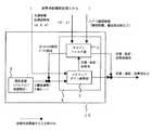
図1(a)は、実施の形態1の慣性装置が搭載される飛しょう体20の構成を示した図である。図1(b)は赤外線センサ1を含む面(A-B面)における飛しょう体20の断面図である。
ここでは飛しょう体20の機体座標において、Xb軸を飛しょう体20の長手方向に中心軸にとり、Zb軸をXb軸が水平方向を向いた状態での鉛直下方にとり、Yb軸を右手系の3軸直行座標系を構成するように設定する。また、地球固定の局地水平座標系(NED)から機体軸への変換に必要となるオイラー角(φ,θ,ψ)により、機体の姿勢角を定義する。すなわち、機体座標軸(Xb、Yb、Zb)周りの回転角を各々(φ,θ,ψ)=(ロール角、ピッチ角、ヨー角)とする。
Fig.1 (a) is the figure which showed the structure of the
Here, in the airframe coordinates of the
飛しょう体20は、胴体15外周に90度間隔で配置された4個の赤外線センサ1(1a、1b、1c、1d)と、機体軸Xbと同一の方向に2個のGPSアンテナ2(2a、2b)と、姿勢角初期推定部5と、航法装置10とを備える。
胴体15外周に配置された4個の赤外線センサのうち、赤外線センサ1aが配置された位置の機体座標軸Xb周りの回転角φをφ=0[deg]とする。2個のGPSアンテナ2a、2bは赤外線センサ1aと同一の回転角、すなわちφ=0[deg]の角度に配置されている。GPSアンテナ2は、φ=θ=0 [deg]の時、GPSアンテナ2のボアサイト方向が天頂方向を向くように設置される。また、2個のGPSアンテナ2a、2bの間隔は数十センチ〜数メートル程度とする(図1(b)参照)。The
Of the four infrared sensors arranged on the outer periphery of the fuselage 15, the rotation angle φ around the body coordinate axis Xb at the position where the infrared sensor 1a is arranged is φ = 0 [deg]. The two
図2は、姿勢角初期推定部5の構成を示す図である。姿勢角初期推定部5は、GPSジャイロ4とロール角推定部13を備える。GPSジャイロ4はGPSアンテナ2a、2bと接続し、GPS衛星からRF信号(GPS信号ともいう)を受信して機体の位置座標と、機体のピッチ角θ、ヨー角ψを出力する。 FIG. 2 is a diagram illustrating a configuration of the attitude angle
図3は、GPSジャイロ4の構成の一例を示した図である。このGPSジャイロ4は、一般的なものであり、GPSアンテナ2a、2bと各々接続したGPS受信機41a、41bと、GPS受信機41からのGPS観測情報によってGPSアンテナ2a、2b間の基線ベクトルを計算する基線ベクトル計算部42とを備えている。GPS受信機41aはGPS衛星から受信したRF信号により、GPS観測情報と測位結果(機体の位置座標)を出力する。基線ベクトル計算部42は、基線ベクトルから機体のピッチ角θとヨー角ψを算出する。 FIG. 3 is a diagram showing an example of the configuration of the
ロール角推定部13は、4個の赤外線センサ1(1a、1b、1c、1d)と接続しており、赤外線センサ1からの情報に基づきロール角φを推定する。ロール角推定部13が行うロール角φの推定については後ほど説明する。 The roll
図4は、航法装置10の構成の一例を示した図である。航法装置10は、飛しょう体の加速度や角加速度等の慣性情報を出力するジャイロや加速度計等からなる慣性装置6と航法計算部9とからなる。
慣性装置6は、3軸のジャイロと3軸の加速度計から構成され、各々3軸(Xb、Yb、Zb)周りの角速度と加速度を出力する。
航法計算部9は、ストラップダウン演算部7とカルマンフィルタ部8とからなる。ストラップダウン演算部7は、姿勢角初期推定部5から得た3軸の姿勢角(φ,θ,ψ)と機体の位置座標を初期値として、慣性装置6からの3軸(Xb、Yb、Zb)周りの角速度と加速度のデータをもとにストラップダウン演算を行い、飛しょう体20の姿勢角(φ,θ,ψ)、位置および速度を計算する。なお、ストラップダウン演算については例えば特開2006-138834に記載がある。FIG. 4 is a diagram illustrating an example of the configuration of the
The inertial device 6 includes a three-axis gyro and a three-axis accelerometer, and outputs angular velocity and acceleration around three axes (Xb, Yb, Zb), respectively.
The
ここで、ジャイロや加速度計は、バイアス誤差やスケールファクタ誤差などを持ち誤差量はドリフトするため、飛しょう時間が長時間になる場合や、姿勢角初期値推定部から得た姿勢角初期値の精度が悪い場合には計算誤差が大きくなってしまう。このため、カルマンフィルタ部8は、ストラップダウン演算部7が出力する姿勢角(φ,θ,ψ)、位置、速度と、姿勢角初期推定部5内のGPSジャイロ4が出力する機体のピッチ角θ、ヨー角ψと、姿勢角初期推定部5内のGPS受信機1が出力する擬似距離や搬送波位相等のGPS観測情報を入力して、各種誤差(位置誤差、速度誤差、姿勢角誤差、ジャイロバイアス誤差、加速度計バイアス誤差、ジャイロスケールファクタ誤差、加速度計スケールファクタ誤差)を推定し、推定したこれらの誤差を補正データとして出力する。ストラップダウン演算部7は補正データにより姿勢角(φ,θ,ψ)、位置および速度を補正して、精度の高い機体の姿勢角、位置および速度を出力する。 Here, gyroscopes and accelerometers have bias errors, scale factor errors, etc., and the amount of error drifts, so if the flight time is long or the posture angle initial value obtained from the posture angle initial value estimation unit is If the accuracy is poor, the calculation error becomes large. For this reason, the Kalman filter unit 8 includes the attitude angle (φ, θ, ψ), position, and speed output from the
図5は、飛しょう体20の外周に設けられている赤外線センサ1の構成の一例を示す図である。赤外線センサ1は、例えば波長1〜100[μm]の赤外線を透過する光学フィルタ31と、赤外線を透過するレンズ32と、熱電堆(熱電対列、thermopile)とから構成されている。赤外線センサ1内には光学フィルタ31を通して赤外線のみが入射するようになっており、赤外線はレンズ32により熱電堆33に集光され、熱電堆33で生じた温度変化が電圧信号として出力される。熱電堆33には、赤外線の入射量に対してほぼ比例する電圧を出力するものを用いる。 FIG. 5 is a diagram illustrating an example of the configuration of the
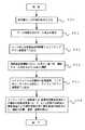
次に図1〜図6を用いて、この実施の形態に係る慣性装置の移動中における調定方法について説明する。図6は、慣性装置の調定方法のフローを示した図である。
飛しょう中に何らかの原因により機体の姿勢角(φ,θ,ψ)が不明となった状況において、ロール角推定部13は、飛しょう体1の胴体外周に配置された各赤外線センサ1a、1b、1c、1dが出力する電圧信号を入力する(図6のステップS01)。地球表面は空と比べると温度が高いため、地球表面と空が各々放射する赤外線の放射量が大きく異なる。例えば赤外線センサ1の指向方向が完全に地球表面を向いている場合は赤外線センサ1からの電圧信号が最大となる。一方、赤外線センサ1の指向方向が完全に空を向いている場合は赤外線センサ1からの電圧信号は最小となる。赤外線センサが地平線方向を向いている場合には、地球表面を向いている場合と空を向いている場合の間の出力をとる。
この原理を利用してロール角推定部13は、赤外線センサ1の電圧信号の出力値に基づき数1により機体のロール角φを算出する(S02)。Next, the adjustment method during the movement of the inertial device according to this embodiment will be described with reference to FIGS. FIG. 6 is a diagram showing a flow of the inertial device adjustment method.
In a situation where the attitude angle (φ, θ, ψ) of the airframe is unknown for some reason during the flight, the roll
Using this principle, the

ロール角推定部13は、算出したロール角φを初期ロール角として、操舵装置制御部3とストラップダウン演算部7に出力する(S03)。操舵装置制御部3では、入力したロール角φに基づき、機体の操舵装置を制御し、機体のロール角をφ=0[deg]となるように制御する(S04)。機体の制御は、例えば、機体に設けられた操舵翼等により行う。これにより、GPS装置4に含まれるGPSアンテナ2のボアサイト方向を安定して天頂付近に向けることができるため、GPSジャイロのアンテナ2はGPS信号が観測できる状態になる。 The roll
次に図3に示したGPSジャイロ4が、GPS受信機41a、41bからのGPS観測情報によって2個のGPSアンテナ間の基線ベクトルを計算し、機体のピッチ角θ、ヨー角ψを求める。GPSジャイロ4は、算出したピッチ角θとヨー角ψを初期ピッチ角と初期ヨー角としてストラップダウン演算部7に出力する。また、GPSジャイロ4は、GPS観測情報から算出される位置座標を初期位置座標としてストラップダウン演算部7に出力する(S05)。 Next, the
ストラップダウン演算部7は、姿勢角初期推定部5から入力した機体の初期ロール角φと初期ピッチ角θと初期ヨー角ψと初期位置座標と、慣性装置6から入力した機体の角速度と加速度とに基づき、慣性装置を調定して飛しょう体の位置と速度と姿勢角を算出する(S06)。このようにストラップダウン演算部7は、姿勢角初期推定部5から初期姿勢角(φ、θ、ψ)と初期位置座標の情報を得ることで、慣性装置の調定を実施可能として、機体の位置と速度と姿勢角を算出する。 The
このように実施の形態1では、飛しょう体外周に複数の赤外線センサ1を備えるようにした。上記ステップS01〜S02では、各赤外線センサからの出力情報を用いることで機体のロール角φを算出することを可能とした。上記ステップS03〜S06では、ロール角φに基づきGPSアンテナ2のボアサイト方向を安定して天頂付近に向けることができるため、飛しょう体がGPS信号が観測できる状態にしてGPSジャイロ4がGPS信号が観測できる状態にあるGPSアンテナの受信情報から、機体の位置座標とピッチ角θとヨー角ψを算出することができるようにした。ストラップ演算部7は、姿勢角初期推定部5から機体の姿勢角(φ、θ、ψ)と位置座標の初期値を得て慣性装置の調定を行い、機体の位置、速度、姿勢角を算出しするようにした。 Thus, in
このようにこの実施の形態1では、飛しょう中の機体の姿勢角が全く分かない状態であっても、慣性装置の調定を短時間に行うことができる。これにより、飛しょう体が移動中に姿勢の制御を失うことがある場合であっても短時間でその姿勢を再度制御可能とすることができる。また、飛しょう体が飛行開始までの時間を短縮することができる。 As described above, in the first embodiment, the inertial device can be adjusted in a short time even when the attitude angle of the flying aircraft is completely unknown. Thereby, even when the flying object sometimes loses control of the posture while moving, the posture can be controlled again in a short time. In addition, the time until the flying object starts to fly can be shortened.
なお、実施の形態1に示した方法により慣性装置6の調定が完了した後は、ストラップダウン演算部7はロール角推定部13が出力するロール角φは用いず、機体の姿勢角、位置および速度の算出を行う。
慣性装置6の調定が完了した後においては、GPSジャイロ4が、GPS受信機41a、41bからの観測データによって2個のGPSアンテナ間の基線ベクトルを計算し、機体のピッチ角θ、ヨー角ψを求めてカルマンフィルタ8に出力する。また、GPS受信機41aは、GPSアンテナ1aが受信したRF信号から得たGPS観測情報をカルマンフィルタ8に出力する。
カルマンフィルタ8は、ストラップダウン演算部7が出力する機体の位置、速度、姿勢角(φ,θ,ψ)と、姿勢角初期推定部5内のGPSジャイロ4が出力する機体のピッチ角θ、ヨー角ψと、擬似距離や搬送波位相等のGPS観測情報を入力して、各種誤差(位置誤差、速度誤差、姿勢角誤差、ジャイロバイアス誤差、加速度計バイアス誤差、ジャイロスケールファクタ誤差、加速度計スケールファクタ誤差など)を推定して、推定したこれらの誤差を補正データとして出力する。そして、ストラップダウン演算部7は補正データにより位置、速度、姿勢角を補正することで、精度の高い機体の姿勢角、位置および速度を取得することができる。。
なお、カルマンフィルタには非線形の系に対して適用できる拡張カルマンフィルタを用いることができる。飛しょう中は常に上記観測更新計算を行い、ストラップダウン演算部に航法補正データをフィードバックすることで、ストラップダウン演算によって得られる位置、速度、加速度計算を精度良く行うことができる。
このように、飛しょう中の機体の姿勢角が全く分かない状態であっても短時間に機体の姿勢角を推定することができて慣性装置の移動中の調定が可能となり、調定完了後はカルマンフィルタを用いることで、高精度に機体の位置、速度、姿勢角を計算して出力することが可能となる。After the adjustment of the inertial device 6 is completed by the method shown in the first embodiment, the
After the adjustment of the inertial device 6 is completed, the
The Kalman filter 8 includes the position, speed, and attitude angle (φ, θ, ψ) of the aircraft output from the
As the Kalman filter, an extended Kalman filter that can be applied to a nonlinear system can be used. During the flight, the above observation update calculation is always performed, and the navigation correction data is fed back to the strapdown calculation unit, so that the position, speed, and acceleration obtained by the strapdown calculation can be calculated with high accuracy.
In this way, even if the attitude angle of the flying aircraft is not known at all, the attitude angle of the aircraft can be estimated in a short time and the inertial device can be adjusted while moving, and the adjustment is completed After that, by using the Kalman filter, it is possible to calculate and output the position, speed, and attitude angle of the aircraft with high accuracy.
なお、実施の形態1の赤外線センサー1ではレンズを用いて光学フィルター透過後の赤外線を熱電堆に集光したが、レンズはなく直接熱電堆で赤外線を受けるようにしてもよい。
また、赤外線センサ1の光学フィルタ31の透過波長は1〜100[μm]に限られるものではなく、地球表面から放射される波長に合わせて適宜設定すればよい。In the
Further, the transmission wavelength of the optical filter 31 of the
また、実施の形態1では、赤外線センサーを機体外周に4個配置したが、4個に限定されるものではなく、赤外線センサからの電圧出力により機体の姿勢角が算出されるものであればその配置数は4個以外であってもよく、例えば3個や5個であってもよい。 In the first embodiment, four infrared sensors are arranged on the outer periphery of the aircraft. However, the number of infrared sensors is not limited to four. If the attitude angle of the aircraft is calculated by the voltage output from the infrared sensor, The number of arrangement may be other than four, for example, three or five.
また、実施の形態1では熱電堆33を用い熱電堆が出力する電圧に基づき初期のロール角を算出したが、赤外線センサにCCD素子を搭載し、CCD素子が出力する画像情報から水平線を認識し、各CCD素子からの画像の水平線の角度情報から初期のロール角を算出するようにしてもよい。 In the first embodiment, the initial roll angle is calculated based on the voltage output from the
1a〜1d 赤外線センサ、2a、2b GPSアンテナ、3 操舵装置制御部、4 GPSジャイロ、5 姿勢角初期推定部、6 慣性装置、7 ストラップダウン演算部、8 カルマンフィルタ部、9 航法計算部、10 航法装置、13 ロール角推定部、15 飛しょう体20の胴体、20 飛しょう体、31 光学フィルタ、32 レンズ、33 熱電堆、41a GPS受信機1、41b GPS受信機2 1a to 1d Infrared sensor, 2a, 2b GPS antenna, 3 steering device control unit, 4 GPS gyro, 5 attitude angle initial estimation unit, 6 inertial device, 7 strapdown calculation unit, 8 Kalman filter unit, 9 navigation calculation unit, 10 navigation Device, 13 Roll angle estimation unit, 15 Body of flying
Claims (4)
Translated fromJapanese前記姿勢角初期推定手段から入力した前記ロール角に基づき、前記GPSジャイロがGPS衛星からのGPS信号を受信可能な姿勢に制御する操舵装置制御手段と、
前記飛しょう体に搭載した慣性装置から入力した慣性情報と、前記姿勢角初期推定部から入力した前記飛しょう体の位置座標とロール角とピッチ角とヨー角とに基づき、前記慣性装置を調定して前記飛しょう体の位置と姿勢角を算出する航法装置と、を備えることを特徴とする飛しょう体。Roll angle estimation means for obtaining the roll angle of the flying object based on output information from a plurality of infrared sensors provided on the outer periphery of the flying body, and calculating the position coordinates, pitch angle and yaw angle of the flying object Attitude angle initial estimation means having a GPS gyro
Steering device control means for controlling the GPS gyro to an attitude capable of receiving GPS signals from GPS satellites based on the roll angle input from the attitude angle initial estimating means;
The inertial device is adjusted based on the inertial information input from the inertial device mounted on the flying object and the position coordinates, roll angle, pitch angle, and yaw angle of the flying object input from the attitude angle initial estimating unit. And a navigation device for calculating a position and an attitude angle of the flying object.
前記姿勢角初期推定手段は、各赤外線センサが出力する前記電圧値に基づき前記飛しょう体のロール角を算出する請求項1記載の飛しょう体。The infrared sensor includes a thermopile that outputs a voltage value corresponding to the amount of incident infrared rays,
The flying object according to claim 1, wherein the posture angle initial estimating unit calculates a roll angle of the flying object based on the voltage value output from each infrared sensor.
前記ロール角に基づき、前記操舵装置制御手段が飛しょう体に搭載されるGPSジャイロがGPS衛星からのGPS信号を受信可能な姿勢に制御するステップと、
前記GPSジャイロが、前記飛しょう体の位置座標とピッチ角とヨー角とを算出してストラップダウン演算手段に出力するステップと、
前記ストラップダウン演算手段が、前記ロール角と前記ピッチ角と前記ヨー角と前記位置座標と、飛しょう体に搭載された慣性装置からの慣性情報とに基づき前記慣性装置を調定するステップと、を備えることを特徴とする飛しょう体に搭載される慣性装置の調定方法。Obtaining a roll angle of the flying body based on output information from an infrared sensor provided on the outer periphery of the flying body, and outputting to the steering device control means and the strapdown calculation means;
Based on the roll angle, the steering device control means controls the GPS gyro mounted on the flying body to an attitude capable of receiving GPS signals from GPS satellites;
The GPS gyro calculating the position coordinates, pitch angle and yaw angle of the flying object and outputting them to a strapdown computing means;
The strapdown computing means adjusts the inertial device based on the roll angle, the pitch angle, the yaw angle, the position coordinates, and inertial information from the inertial device mounted on the flying object; A method for adjusting an inertial device mounted on a flying body, characterized by comprising:
Priority Applications (1)
| Application Number | Priority Date | Filing Date | Title |
|---|---|---|---|
| JP2007079074AJP2008241320A (en) | 2007-03-26 | 2007-03-26 | Method for adjusting flying body and inertial device mounted on flying body |
Applications Claiming Priority (1)
| Application Number | Priority Date | Filing Date | Title |
|---|---|---|---|
| JP2007079074AJP2008241320A (en) | 2007-03-26 | 2007-03-26 | Method for adjusting flying body and inertial device mounted on flying body |
Publications (1)
| Publication Number | Publication Date |
|---|---|
| JP2008241320Atrue JP2008241320A (en) | 2008-10-09 |
Family
ID=39912872
Family Applications (1)
| Application Number | Title | Priority Date | Filing Date |
|---|---|---|---|
| JP2007079074APendingJP2008241320A (en) | 2007-03-26 | 2007-03-26 | Method for adjusting flying body and inertial device mounted on flying body |
Country Status (1)
| Country | Link |
|---|---|
| JP (1) | JP2008241320A (en) |
Cited By (6)
| Publication number | Priority date | Publication date | Assignee | Title |
|---|---|---|---|---|
| JP2011163589A (en)* | 2010-02-05 | 2011-08-25 | Mitsubishi Electric Corp | Guided flying object device |
| EP2594890A1 (en)* | 2011-11-18 | 2013-05-22 | Simmonds Precision Products, Inc. | Ratio-metric horizon sensing using an array of thermopiles |
| CN103822636A (en)* | 2014-03-18 | 2014-05-28 | 中国航天时代电子公司 | Air-to-surface guided weapon strapdown homing sight reconstruction method |
| CN112649001A (en)* | 2020-12-01 | 2021-04-13 | 中国航空工业集团公司沈阳飞机设计研究所 | Method for resolving attitude and position of small unmanned aerial vehicle |
| CN113108779A (en)* | 2021-03-11 | 2021-07-13 | 上海航天控制技术研究所 | Independent arrow measurement system based on 1553B bus triple redundancy |
| CN113984042A (en)* | 2021-08-31 | 2022-01-28 | 惠州学院 | Series combination navigation method suitable for high-dynamic aircraft |
- 2007
- 2007-03-26JPJP2007079074Apatent/JP2008241320A/enactivePending
Cited By (11)
| Publication number | Priority date | Publication date | Assignee | Title |
|---|---|---|---|---|
| JP2011163589A (en)* | 2010-02-05 | 2011-08-25 | Mitsubishi Electric Corp | Guided flying object device |
| EP2594890A1 (en)* | 2011-11-18 | 2013-05-22 | Simmonds Precision Products, Inc. | Ratio-metric horizon sensing using an array of thermopiles |
| US8561898B2 (en) | 2011-11-18 | 2013-10-22 | Simmonds Precision Products, Inc. | Ratio-metric horizon sensing using an array of thermopiles |
| CN103822636A (en)* | 2014-03-18 | 2014-05-28 | 中国航天时代电子公司 | Air-to-surface guided weapon strapdown homing sight reconstruction method |
| CN103822636B (en)* | 2014-03-18 | 2016-10-05 | 中国航天时代电子公司 | A kind of Air-to-Surface Guided Weapon strapdown homing Line-of-sight reconstruction method |
| CN112649001A (en)* | 2020-12-01 | 2021-04-13 | 中国航空工业集团公司沈阳飞机设计研究所 | Method for resolving attitude and position of small unmanned aerial vehicle |
| CN112649001B (en)* | 2020-12-01 | 2023-08-22 | 中国航空工业集团公司沈阳飞机设计研究所 | Gesture and position resolving method for small unmanned aerial vehicle |
| CN113108779A (en)* | 2021-03-11 | 2021-07-13 | 上海航天控制技术研究所 | Independent arrow measurement system based on 1553B bus triple redundancy |
| CN113108779B (en)* | 2021-03-11 | 2022-10-28 | 上海航天控制技术研究所 | Independent arrow measurement system based on 1553B bus triple redundancy |
| CN113984042A (en)* | 2021-08-31 | 2022-01-28 | 惠州学院 | Series combination navigation method suitable for high-dynamic aircraft |
| CN113984042B (en)* | 2021-08-31 | 2023-10-17 | 惠州学院 | Series combined navigation method applicable to high-dynamic aircraft |
Similar Documents
| Publication | Publication Date | Title |
|---|---|---|
| US6463366B2 (en) | Attitude determination and alignment using electro-optical sensors and global navigation satellites | |
| US11168984B2 (en) | Celestial navigation system and method | |
| CA2837179C (en) | Determining spatial orientation information of a body from multiple electromagnetic signals | |
| KR100761011B1 (en) | Posture Correction Apparatus and Method for Inertial Navigation System Using Camera-type Solar Sensor | |
| US8213803B2 (en) | Method and system for laser based communication | |
| US7328104B2 (en) | Systems and methods for improved inertial navigation | |
| US9593963B2 (en) | Method and a device for determining navigation parameters of an aircraft during a landing phase | |
| EP3040680B1 (en) | Magnetic anomaly tracking for an inertial navigation system | |
| AU2014208314A1 (en) | Method And System For Remotely Controlling A Vehicle | |
| CN104698486A (en) | Real-time navigation method of data processing computer system for distributed POS | |
| JP2008241320A (en) | Method for adjusting flying body and inertial device mounted on flying body | |
| KR20140034716A (en) | System and method for measurement of angular orientation of aerospace platforms | |
| EP4027173A1 (en) | Personal navigation device operable in gnss-denied environment | |
| US9217639B1 (en) | North-finding using inertial navigation system | |
| US9395447B2 (en) | Orientation measurements for drift correction | |
| US9382020B1 (en) | Deep space positioning system | |
| JP2008232867A (en) | Attitude and azimuth detector for moving object | |
| US20080004758A1 (en) | Apparatus and method for tracking an orbital body relative to a planetary body using a single sensor | |
| EP4584556A1 (en) | Method and system for determining initial heading angle | |
| JP2002162195A (en) | Flying object guidance device | |
| Theil et al. | Hybrid navigation system for spaceplanes, launch and re-entry vehicles | |
| EP3662343B1 (en) | In-flight azimuth determination | |
| RU118738U1 (en) | INTEGRATED FREE PLATFORM INERTIAL OPTICAL SYSTEM FOR SPACE AIRCRAFT | |
| US11626661B2 (en) | Vehicle having antenna positioner adjusted for timing latency and associated methods | |
| Steffes et al. | Alignment between IMU and star tracker using the night sky and an on-board navigation system |