JP2008238053A - Cyclone apparatus - Google Patents
Cyclone apparatusDownload PDFInfo
- Publication number
- JP2008238053A JP2008238053AJP2007082066AJP2007082066AJP2008238053AJP 2008238053 AJP2008238053 AJP 2008238053AJP 2007082066 AJP2007082066 AJP 2007082066AJP 2007082066 AJP2007082066 AJP 2007082066AJP 2008238053 AJP2008238053 AJP 2008238053A
- Authority
- JP
- Japan
- Prior art keywords
- cyclone
- duct
- exhaust gas
- fine powder
- port
- Prior art date
- Legal status (The legal status is an assumption and is not a legal conclusion. Google has not performed a legal analysis and makes no representation as to the accuracy of the status listed.)
- Pending
Links
- 239000000843powderSubstances0.000claimsabstractdescription30
- 238000000926separation methodMethods0.000claimsdescription4
- 239000006185dispersionSubstances0.000abstractdescription4
- 239000007789gasSubstances0.000description22
- 238000011084recoveryMethods0.000description4
- 238000007689inspectionMethods0.000description3
- 230000000903blocking effectEffects0.000description2
- 238000009434installationMethods0.000description2
- 239000000463materialSubstances0.000description2
- 239000003607modifierSubstances0.000description2
- 239000010815organic wasteSubstances0.000description2
- 239000010801sewage sludgeSubstances0.000description2
- 239000010802sludgeSubstances0.000description2
- 239000002689soilSubstances0.000description2
- 239000002912waste gasSubstances0.000description2
- 239000002699waste materialSubstances0.000description2
- 238000010586diagramMethods0.000description1
- 238000007599dischargingMethods0.000description1
- 238000001035dryingMethods0.000description1
- 239000003337fertilizerSubstances0.000description1
- 239000000446fuelSubstances0.000description1
- 238000000034methodMethods0.000description1
Images


Classifications
- B—PERFORMING OPERATIONS; TRANSPORTING
- B04—CENTRIFUGAL APPARATUS OR MACHINES FOR CARRYING-OUT PHYSICAL OR CHEMICAL PROCESSES
- B04C—APPARATUS USING FREE VORTEX FLOW, e.g. CYCLONES
- B04C5/00—Apparatus in which the axial direction of the vortex is reversed
- B04C5/24—Multiple arrangement thereof
- B04C5/28—Multiple arrangement thereof for parallel flow
- B—PERFORMING OPERATIONS; TRANSPORTING
- B04—CENTRIFUGAL APPARATUS OR MACHINES FOR CARRYING-OUT PHYSICAL OR CHEMICAL PROCESSES
- B04C—APPARATUS USING FREE VORTEX FLOW, e.g. CYCLONES
- B04C5/00—Apparatus in which the axial direction of the vortex is reversed
- B04C5/02—Construction of inlets by which the vortex flow is generated, e.g. tangential admission, the fluid flow being forced to follow a downward path by spirally wound bulkheads, or with slightly downwardly-directed tangential admission
- B04C5/04—Tangential inlets
Landscapes
- Physics & Mathematics (AREA)
- Fluid Mechanics (AREA)
- Cyclones (AREA)
Abstract
Description
Translated fromJapanese本発明は乾燥機等の処理装置から排気される排ガス中に含まれる粉体を分離・回収する装置に関するものであって、特に給気構造の改良を施したサイクロン装置に係るものである。 The present invention relates to an apparatus for separating and recovering powder contained in exhaust gas exhausted from a processing apparatus such as a dryer, and particularly relates to a cyclone apparatus having an improved air supply structure.
生ごみ・食品加工残渣等の一般廃棄物や下水汚泥等、有機系廃棄物の処理形態の一つに、図5に示すような乾燥機である処理装置1′用いて乾燥品Dを得て、肥料、燃料、土壌改質剤、土木基材等として再利用するものがある(例えば特許文献1参照)。
このような処理形態においては、有機系汚泥等を処理装置1′において乾燥するとともに、サイクロン装置4′において処理装置1′から排気された排ガスG中の微粉dを分離・回収した後、これらを処理装置1′から排出された乾燥品Dに混入して有効利用することが行われている。Obtain a dried product D using one of the treatment devices 1 ', which is a dryer as shown in Fig. 5, as one of the treatment methods for organic waste such as general waste such as garbage and food processing residue and sewage sludge. , Fertilizers, fuels, soil modifiers, civil engineering base materials, and the like (see, for example, Patent Document 1).
In such a treatment mode, organic sludge and the like are dried in the
このとき処理工場のレイアウトの制限等により、サイクロンユニット41′、42′(排出口44′)が直接移送装置3′の上方に位置するような装置構成が採られた場合、処理装置1′の排気口14′と、サイクロンユニット41′、42′の給気口43′との間を結ぶダクト40′が直線状のものではなく屈曲部R′を有するものとなってしまうことがあった。
そしてこのようにダクト40′が屈曲部R′を有した場合、特に回収効率を高めるために二基以上のサイクロンユニット41′、42′によりサイクロン装置4′が構成されたときに、以下に示すような問題が生じてしまっていた。
すなわち処理装置1′の排気口14′から排出された排ガスGは、給気口43′に向かって進行する際に屈曲部R′において方向を変えることとなるが、このとき、遠心力によって排ガスG中の微粉dが外側に偏移してしまい、この結果、一方のサイクロンユニット41′の方に多くの微粉dが投入されてしまう。
この結果、排出口44′の閉塞や、排出口44′に接続されるロータリーバルブ45′の能力オーバーといった不具合が生じて装置全体の運転を阻害してしまうことがあった。
When the duct 40 'has the bent portion R' as described above, particularly when the cyclone device 4 'is constituted by two or more cyclone units 41' and 42 'in order to increase the recovery efficiency, the following is shown. Such a problem has occurred.
That is, the exhaust gas G discharged from the exhaust port 14 'of the processing apparatus 1' changes direction at the bent portion R 'when traveling toward the air supply port 43'. At this time, the exhaust gas G is exhausted by centrifugal force. The fine powder d in G shifts to the outside, and as a result, a large amount of fine powder d is thrown into one
As a result, problems such as blocking of the
本発明はこのような背景から成されたものであって、二基以上のサイクロンユニットに対して、排気ガス中の微粉を均等に供給することのできる、新規なサイクロン装置の開発を技術課題としたものである。 The present invention is made from such a background, and it is a technical problem to develop a new cyclone device that can uniformly supply fine powder in exhaust gas to two or more cyclone units. It is a thing.
すなわち請求項1記載のサイクロン装置は、乾燥機等の処理装置から排気される排ガス中に含まれる粉体を分離・回収する分離装置において、前記分離装置は二基以上のサイクロンユニットを並列配置して成るものであり、また前記処理装置における排気口と、サイクロンユニットの給気口とを結ぶダクトは屈曲したものであり、このダクト内部に整流板を具えたことを特徴として成るものである。
この発明によれば、整流板にダクト内を進行する排ガスを衝突させることにより乱流を生じさせ、排ガス内で偏移している微粉をガス成分内に均等に分散させることができ、各サイクロンユニットに対して均等に微粉を供給することが可能となる。That is, the cyclone device according to
According to the present invention, the exhaust gas traveling in the duct collides with the rectifying plate to generate turbulent flow, and the fine powder shifted in the exhaust gas can be evenly dispersed in the gas component. It becomes possible to supply fine powder evenly to the unit.
また請求項2記載のサイクロン装置は、前記要件に加え、前記整流板は、サイクロンユニットの給気口と、この給気口に最も近い屈曲部との間に具えられていることを特徴として成るものである。
この発明によれば、微粉が均等に分散させられ状態の排ガスを迅速にサイクロンユニットに供給することができる。In addition to the above requirements, the cyclone device according to claim 2 is characterized in that the rectifying plate is provided between an air supply port of the cyclone unit and a bent portion closest to the air supply port. Is.
According to this invention, the exhaust gas in a state where fine powder is uniformly dispersed can be quickly supplied to the cyclone unit.
更にまた請求項3記載のサイクロン装置は、前記要件に加え、前記整流板は可動式のものであることを特徴として成るものである。
この発明によれば、排ガスの流量や流速、あるいは微粉の性状等に応じて整流板の設置状態を異ならせることにより、微粉の分散状態を所望のものとすることができる。Furthermore, the cyclone device according to
According to this invention, the dispersion state of the fine powder can be made desired by varying the installation state of the rectifying plate according to the flow rate and flow velocity of the exhaust gas or the properties of the fine powder.
更にまた請求項4記載のサイクロン装置は、前記請求項3記載の要件に加え、前記整流板は、ダクト外部に突出状態となったハンドルによって設定個所の変更が可能となっていることを特徴として成るものである。
この発明によれば、運転中に整流板の状態を調整して排ガスの乱流具合を変化させ、微粉の分散状態を所望のものとすることができる。
そしてこれら各請求項記載の発明の構成を手段として前記課題の解決が図られる。Furthermore, the cyclone device according to
According to this invention, the state of the rectifying plate can be adjusted during operation to change the turbulent state of the exhaust gas, and the dispersion state of the fine powder can be made desired.
The above problems can be solved by using the configuration of the invention described in each of the claims as a means.
本発明によれば、並列配置された複数のサイクロンユニットの給気口に接続されるダクトが屈曲部を有するものであっても、各々のサイクロンユニットに対して均等に微粉を供給することができ、サイクロンユニットに所望の性能を発揮させて装置全体の安定運転を実現することが可能となる。 According to the present invention, even if the duct connected to the air supply ports of a plurality of cyclone units arranged in parallel has a bent portion, fine powder can be supplied uniformly to each cyclone unit. The cyclone unit can exhibit desired performance to achieve stable operation of the entire apparatus.
以下本発明の「サイクロン装置」について、図示の実施例に基づいて説明するものであるが、この実施例に対して本発明の技術的思想の範囲内において適宜変更を加えることも可能である。 Hereinafter, the “cyclone device” of the present invention will be described based on the illustrated embodiment. However, it is possible to appropriately modify this embodiment within the scope of the technical idea of the present invention.
本発明の適用対象の一例である有機系汚泥の処理施設Sは図1に示すように、乾燥機等の処理装置1と、この処理装置1から排気される排ガスG中に含まれる粉体(以下微粉dと呼ぶ。)を分離・回収するサイクロン装置4とを主要部材として具えて成るものである。
また前記サイクロン装置4は二基以上のサイクロンユニット41、42を並列配置して構成されるものである。As shown in FIG. 1, an organic sludge treatment facility S which is an example of an application target of the present invention includes a
The
まず前記処理装置1たる乾燥機について説明するとこのものは図1に示すように、回転可能に具えられた本体シェル10内に熱風を供給し、本体シェル10内に投入された被処理物を加熱して乾燥を行う装置である。
前記本体シェル10は一例として中空円筒状の部材であり、その両端に接続される蓋体には、投入口11及び熱風口13並びに排出口12及び排気口14が形成される。
なお前記本体シェル10は、水平または投入口11側が排出口12側よりもいくぶんか高くなるように傾斜して取り付けられる。First, the dryer as the
The
The
そして前記投入口11に対しては、ホッパ20を具えた投入装置2が接続され、また前記排出口12に対しては、スクリューコンベヤ、ベルトコンベヤ等の移送装置3が接続され、更にまた前記熱風口13に対しては、熱風炉16が接続され、更にまた排気口14に対しては、サイクロン装置4が接続される。
なおこの実施例では、前記移送装置3としてスクリュ−コンベヤが適用されるものであり、そのケーシングには受入口3a及び回収口3bが形成される。
そして前記処理装置1における排出口12と、移送装置3における受入口3aとの間は排出管路15によって接続される。A charging device 2 including a
In this embodiment, a screw conveyor is applied as the
The
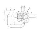
ここで前記サイクロン装置4について説明すると、このものは一例として同型の二基のサイクロンユニット41及びサイクロンユニット42並びにダクト40を具えて構成されるものであり、それぞれのサイクロンユニット41、サイクロンユニット42は、図2の平面図に示すように処理装置1における排気口14と接続されたダクト40に対して並列に接続される。
そしてこのような並列接続を行う場合、ダクト40が屈曲部Rを有するものとなってしまうことがあり、この実施例ではダクト40は平面視でU字状の形状となるため屈曲部Rが二カ所に形成されている。
因みにこの実施例では、サイクロン装置4におけるサイクロンユニット41、42の排出口44が移送装置3における回収口3bの上方に位置するようなレイアウトが採られており、排出口44と回収口3bとが排出管路47によって接続されることにより、排出口44から排出される微粉dが自由落下により移送装置3に取り込まれるように構成されている。Here, the
When such parallel connection is performed, the
Incidentally, in this embodiment, a layout is adopted in which the
また前記ダクト40の終端付近は幅広がり状に形成されており、中央に配されたV字状の分岐板40aによって流路が二路に分岐されている。
そしてこのダクト40に対して整流機構50が具えられるものであり、一例としてダクト40内部におけるサイクロンユニット41、42の給気口43と、この給気口43に最も近い屈曲部Rとの間に整流板51が配される。
なお整流板51は、図4(a)に示すようにダクト40の流路を一部狭めるような状態で配される。The vicinity of the end of the
A
In addition, the
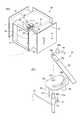
またこの実施例では、整流板51が一定範囲で回動するように構成されるものであり、ダクト40の上下板に具えられた軸受52によって軸53が軸支され、この軸53に対して前記整流板51が固着されている。
更に前記整流板51は、ダクト40外部に突出状態となった軸53の軸端に固定されたハンドル54の操作によって回動することにより、その設定個所の変更が可能となっている。
このような回動機構は図4(b)に示すように、ダクト40の上部に取付脚56によって案内板55が固定され、この案内板55に形成された軸孔55aに挿通された軸53の軸端が、ハンドル54に形成された軸孔54aに嵌め込まれて固定されることにより構成されている。In this embodiment, the rectifying
Further, the rectifying
As shown in FIG. 4 (b), such a rotating mechanism has a
更に前記案内板55にはボルト案内孔55bが湾曲した状態で形成されるものであり、このボルト案内孔55bの下方から、ワッシャー57aをかませてボルト57を挿通するとともに、更にボルト57の先端部をハンドル54に形成されたボルト孔54bに挿通状態とする。そしてボルト57には、レバー58の一端に具えられたナット58aが螺合するものであり、レバー58を操作してナット58aを締め付けることによりハンドル54が固定され、前記整流板51の設定個所が固定されることとなる。 Further, a
本発明のサイクロン装置4を具えた処理施設Sは一例として上述したように構成されるものであり、以下整流機構50の作用について説明する。
図1に示すように、生ごみ・食品加工残渣等の一般廃棄物や下水汚泥等、有機系廃棄物の処理施設Sは、乾燥機である処理装置1用いて乾燥品Dを得て、燃料、土壌改質剤、土木基材等として再利用するものである。
そして、処理装置1から排出される排ガスG中の微粉dをサイクロン装置4によって分離・回収した後、これらを処理装置1から排出された乾燥品Dに混入して有効利用するものである。The processing facility S including the
As shown in FIG. 1, a processing facility S for organic waste, such as general waste such as garbage and food processing residue, and sewage sludge, obtains a dried product D using a
And after separating and collect | recovering the fine powder d in the waste gas G discharged | emitted from the
このとき処理工場のレイアウトの制限等により、ダクト40が直線状のものではなく屈曲部Rを有するものとなってしまう場合には、発明の背景で述べたように、処理装置1の排気口14から排出された排ガスGは、サイクロン装置4の給気口43に向かって進行する際に屈曲部Rにおいて方向を変えることとなるが、このとき、遠心力によって排ガスG中の微粉dが外側に偏移してしまい、この結果、一方のサイクロンユニット41の方に多くの微粉dが投入されてしまう(図5参照)。 At this time, when the
しかしながら図3に示すように、ダクト40に整流機構50が具えられていた場合には、処理装置1の排気口14から排出された排ガスGは、第一の屈曲部R及び第二の屈曲部Rにおいて方向を変える際に遠心力によって微粉dが外側に偏移した状態となってしまうものの、整流板51にぶつかって進路を妨げられて乱流が生じ、この乱流によって微粉dは排ガスG中に均等に分散することとなる。
そして排ガスGはこの状態で分岐板40aに至り、サイクロンユニット41、サイクロンユニット42に同量が供給され、微粉dが分離・回収されるとともにガス成分のみが排気口46から排気されることとなる。
この結果、排出口44の閉塞や、排出口44に接続されるロータリーバルブ45の能力オーバーといった不具合を回避して装置全体の運転を安定して行うことが可能となる。However, as shown in FIG. 3, when the
The exhaust gas G reaches the
As a result, it becomes possible to stably operate the entire apparatus while avoiding problems such as blocking of the
なおダクト40の天板あるいは側板に点検窓Wを形成してもよく、この点検窓Wを通じて排ガスGの乱流具合を視認しながらレバー58を操作し、最適個所に整流板51を固定することにより、微粉dの分散状態を最良のものとすることが可能となる。 An inspection window W may be formed on the top plate or side plate of the
1 処理装置
10 本体シェル
11 投入口
12 排出口
13 熱風口
14 排気口
15 排出管路
16 熱風炉
2 投入装置
20 ホッパ
3 移送装置
3a 受入口
3b 回収口
4 サイクロン装置
40 ダクト
40a 分岐板
41 サイクロンユニット
42 サイクロンユニット
43 給気口
44 排出口
45 ロータリーバルブ
46 排気口
47 排出管路
50 整流機構
51 整流板
52 軸受
53 軸
54 ハンドル
54a 軸孔
54b ボルト孔
55 案内板
55a 軸孔
55b ボルト案内孔
56 取付脚
57 ボルト
57a ワッシャー
58 レバー
58a ナット
D 乾燥品
d 微粉
G 排ガス
R 屈曲部
S 処理施設
W 点検窓DESCRIPTION OF
Claims (4)
Translated fromJapanesePriority Applications (1)
| Application Number | Priority Date | Filing Date | Title |
|---|---|---|---|
| JP2007082066AJP2008238053A (en) | 2007-03-27 | 2007-03-27 | Cyclone apparatus |
Applications Claiming Priority (1)
| Application Number | Priority Date | Filing Date | Title |
|---|---|---|---|
| JP2007082066AJP2008238053A (en) | 2007-03-27 | 2007-03-27 | Cyclone apparatus |
Publications (1)
| Publication Number | Publication Date |
|---|---|
| JP2008238053Atrue JP2008238053A (en) | 2008-10-09 |
Family
ID=39910028
Family Applications (1)
| Application Number | Title | Priority Date | Filing Date |
|---|---|---|---|
| JP2007082066APendingJP2008238053A (en) | 2007-03-27 | 2007-03-27 | Cyclone apparatus |
Country Status (1)
| Country | Link |
|---|---|
| JP (1) | JP2008238053A (en) |
Cited By (16)
| Publication number | Priority date | Publication date | Assignee | Title |
|---|---|---|---|---|
| CN101905196A (en)* | 2010-07-19 | 2010-12-08 | 中国钢研科技集团有限公司 | A method and device for adjusting the air inlet of a double cyclone dust collector |
| CN105143413A (en)* | 2012-12-11 | 2015-12-09 | 弗雷特等离子实验室公司 | High temperature countercurrent vortex reactor system, method and apparatus |
| KR101610665B1 (en) | 2016-02-29 | 2016-04-08 | 한장섭 | An excess supply of dust blocking device for an ascon production plant |
| US9560731B2 (en) | 2007-10-16 | 2017-01-31 | Foret Plasma Labs, Llc | System, method and apparatus for an inductively coupled plasma Arc Whirl filter press |
| US9644465B2 (en) | 2007-10-16 | 2017-05-09 | Foret Plasma Labs, Llc | System, method and apparatus for creating an electrical glow discharge |
| US9781817B2 (en) | 2007-10-16 | 2017-10-03 | Foret Plasma Labs, Llc | High temperature electrolysis glow discharge device |
| US9790108B2 (en) | 2007-10-16 | 2017-10-17 | Foret Plasma Labs, Llc | Water/wastewater recycle and reuse with plasma, activated carbon and energy system |
| US9869277B2 (en) | 2008-02-12 | 2018-01-16 | Foret Plasma Labs, Llc | System, method and apparatus for lean combustion with plasma from an electrical arc |
| US9951942B2 (en) | 2007-10-16 | 2018-04-24 | Foret Plasma Labs, Llc | Solid oxide high temperature electrolysis glow discharge cell |
| US10098191B2 (en) | 2008-02-12 | 2018-10-09 | Forest Plasma Labs, LLC | Inductively coupled plasma arc device |
| US10244614B2 (en) | 2008-02-12 | 2019-03-26 | Foret Plasma Labs, Llc | System, method and apparatus for plasma arc welding ceramics and sapphire |
| US10267106B2 (en) | 2007-10-16 | 2019-04-23 | Foret Plasma Labs, Llc | System, method and apparatus for treating mining byproducts |
| US10395892B2 (en) | 2007-10-16 | 2019-08-27 | Foret Plasma Labs, Llc | High temperature electrolysis glow discharge method |
| US10412820B2 (en) | 2007-10-16 | 2019-09-10 | Foret Plasma Labs, Llc | System, method and apparatus for recovering mining fluids from mining byproducts |
| CN114087701A (en)* | 2020-07-10 | 2022-02-25 | 北京同方洁净技术有限公司 | Dual-channel air filter purification device |
| US11806686B2 (en) | 2007-10-16 | 2023-11-07 | Foret Plasma Labs, Llc | System, method and apparatus for creating an electrical glow discharge |
- 2007
- 2007-03-27JPJP2007082066Apatent/JP2008238053A/enactivePending
Cited By (24)
| Publication number | Priority date | Publication date | Assignee | Title |
|---|---|---|---|---|
| US10018351B2 (en) | 2007-10-16 | 2018-07-10 | Foret Plasma Labs, Llc | Solid oxide high temperature electrolysis glow discharge cell |
| US9644465B2 (en) | 2007-10-16 | 2017-05-09 | Foret Plasma Labs, Llc | System, method and apparatus for creating an electrical glow discharge |
| US11806686B2 (en) | 2007-10-16 | 2023-11-07 | Foret Plasma Labs, Llc | System, method and apparatus for creating an electrical glow discharge |
| US10638592B2 (en) | 2007-10-16 | 2020-04-28 | Foret Plasma Labs, Llc | System, method and apparatus for an inductively coupled plasma arc whirl filter press |
| US10412820B2 (en) | 2007-10-16 | 2019-09-10 | Foret Plasma Labs, Llc | System, method and apparatus for recovering mining fluids from mining byproducts |
| US9560731B2 (en) | 2007-10-16 | 2017-01-31 | Foret Plasma Labs, Llc | System, method and apparatus for an inductively coupled plasma Arc Whirl filter press |
| US9951942B2 (en) | 2007-10-16 | 2018-04-24 | Foret Plasma Labs, Llc | Solid oxide high temperature electrolysis glow discharge cell |
| US10395892B2 (en) | 2007-10-16 | 2019-08-27 | Foret Plasma Labs, Llc | High temperature electrolysis glow discharge method |
| US9781817B2 (en) | 2007-10-16 | 2017-10-03 | Foret Plasma Labs, Llc | High temperature electrolysis glow discharge device |
| US9790108B2 (en) | 2007-10-16 | 2017-10-17 | Foret Plasma Labs, Llc | Water/wastewater recycle and reuse with plasma, activated carbon and energy system |
| US10267106B2 (en) | 2007-10-16 | 2019-04-23 | Foret Plasma Labs, Llc | System, method and apparatus for treating mining byproducts |
| US10117318B2 (en) | 2007-10-16 | 2018-10-30 | Foret Plasma Labs, Llc | High temperature electrolysis glow discharge device |
| US10184322B2 (en) | 2007-10-16 | 2019-01-22 | Foret Plasma Labs, Llc | System, method and apparatus for creating an electrical glow discharge |
| US10098191B2 (en) | 2008-02-12 | 2018-10-09 | Forest Plasma Labs, LLC | Inductively coupled plasma arc device |
| US9869277B2 (en) | 2008-02-12 | 2018-01-16 | Foret Plasma Labs, Llc | System, method and apparatus for lean combustion with plasma from an electrical arc |
| US10244614B2 (en) | 2008-02-12 | 2019-03-26 | Foret Plasma Labs, Llc | System, method and apparatus for plasma arc welding ceramics and sapphire |
| CN101905196A (en)* | 2010-07-19 | 2010-12-08 | 中国钢研科技集团有限公司 | A method and device for adjusting the air inlet of a double cyclone dust collector |
| US10030195B2 (en) | 2012-12-11 | 2018-07-24 | Foret Plasma Labs, Llc | Apparatus and method for sintering proppants |
| CN105143413A (en)* | 2012-12-11 | 2015-12-09 | 弗雷特等离子实验室公司 | High temperature countercurrent vortex reactor system, method and apparatus |
| CN105143413B (en)* | 2012-12-11 | 2017-07-04 | 弗雷特等离子实验室公司 | High temperature countercurrent vortex reactor system, method and device |
| US9499443B2 (en) | 2012-12-11 | 2016-11-22 | Foret Plasma Labs, Llc | Apparatus and method for sintering proppants |
| EP2931849A4 (en)* | 2012-12-11 | 2016-08-10 | Foret Plasma Labs Llc | HIGH TEMPERATURE TURBBACK AND COUNTERCURRENT REACTOR SYSTEM AND METHOD AND APPARATUS THEREOF |
| KR101610665B1 (en) | 2016-02-29 | 2016-04-08 | 한장섭 | An excess supply of dust blocking device for an ascon production plant |
| CN114087701A (en)* | 2020-07-10 | 2022-02-25 | 北京同方洁净技术有限公司 | Dual-channel air filter purification device |
Similar Documents
| Publication | Publication Date | Title |
|---|---|---|
| JP2008238053A (en) | Cyclone apparatus | |
| US9174220B2 (en) | Dryer/grinder | |
| JP5391492B2 (en) | Radial rotary dryer | |
| ATE358080T1 (en) | DEVICE FOR DIVIDING A STREAM OF PARTICLE OR POWDER MATERIAL INTO PARTIAL STREAMS | |
| JPH06503638A (en) | Sludge dewatering method, sludge dewatering equipment, usage of sludge dewatering equipment and sludge drying system | |
| CN204237697U (en) | Multi-functional sludge drier | |
| JP5283392B2 (en) | Air dryer | |
| JP6678263B2 (en) | Organic waste treatment apparatus and treatment method | |
| KR101729994B1 (en) | Low-temperature dry apparatus for sludge using heat transfer media and dry method thereof | |
| JP2004008921A (en) | Dry system for collecting fine powder | |
| RU2015112217A (en) | REACTOR, METHOD FOR REDUCING THE NUMBER OF SOLID PARTICLES IN A GAS FLOW EXITING FROM THE REACTOR, AND APPLICATION OF THE REACTOR | |
| CN101642728A (en) | System and method for pulverizing and dehumidifying | |
| JP2009210176A (en) | Drying apparatus | |
| US8430246B2 (en) | Apparatus and method for sifting feedstock | |
| CN211284112U (en) | Sludge drying device | |
| KR101754971B1 (en) | Compression type disk dryer of sewage sludge | |
| JP2010214319A (en) | Apparatus and method of drying water-containing organic sludge | |
| CN113368997B (en) | Device for treating a material mixture consisting of alternative fuel and interfering substances | |
| JP2010194382A (en) | Drying system and drying method of water-containing organic waste | |
| KR20000052013A (en) | Dry apparatus of sludge | |
| CN110997578A (en) | Apparatus and method for treating organic waste | |
| JP4020717B2 (en) | Carbonization separation apparatus and carbonization treatment method of waste | |
| KR20140112214A (en) | Pulverizer having improved vane wheel | |
| CN112479547A (en) | Sludge drying device and operation method | |
| JP2015028406A (en) | Drier |