JP2008237266A - Endoscopic treatment instrument - Google Patents
Endoscopic treatment instrumentDownload PDFInfo
- Publication number
- JP2008237266A JP2008237266AJP2007078266AJP2007078266AJP2008237266AJP 2008237266 AJP2008237266 AJP 2008237266AJP 2007078266 AJP2007078266 AJP 2007078266AJP 2007078266 AJP2007078266 AJP 2007078266AJP 2008237266 AJP2008237266 AJP 2008237266A
- Authority
- JP
- Japan
- Prior art keywords
- flexible cord
- forceps
- treatment instrument
- rotational force
- tube
- Prior art date
- Legal status (The legal status is an assumption and is not a legal conclusion. Google has not performed a legal analysis and makes no representation as to the accuracy of the status listed.)
- Abandoned
Links
- 238000012277endoscopic treatmentMethods0.000titleabstract2
- 230000037431insertionEffects0.000claimsabstractdescription56
- 238000003780insertionMethods0.000claimsabstractdescription56
- 229920005989resinPolymers0.000claimsabstractdescription13
- 239000011347resinSubstances0.000claimsabstractdescription13
- 230000005540biological transmissionEffects0.000claimsdescription24
- 239000002184metalSubstances0.000abstractdescription4
- 238000009954braidingMethods0.000abstractdescription3
- 238000005452bendingMethods0.000description24
- 239000010410layerSubstances0.000description7
- 229920003002synthetic resinPolymers0.000description5
- 239000000057synthetic resinSubstances0.000description5
- 230000014759maintenance of locationEffects0.000description3
- 238000001574biopsyMethods0.000description2
- 230000035515penetrationEffects0.000description2
- 239000002356single layerSubstances0.000description2
- 229910001111Fine metalInorganic materials0.000description1
- 230000006835compressionEffects0.000description1
- 238000007906compressionMethods0.000description1
- 230000007423decreaseEffects0.000description1
- 238000010586diagramMethods0.000description1
- 238000010438heat treatmentMethods0.000description1
- 238000005286illuminationMethods0.000description1
- 238000000465mouldingMethods0.000description1
- 238000003825pressingMethods0.000description1
- 230000004044responseEffects0.000description1
- 230000004043responsivenessEffects0.000description1
Images


Classifications
- A—HUMAN NECESSITIES
- A61—MEDICAL OR VETERINARY SCIENCE; HYGIENE
- A61B—DIAGNOSIS; SURGERY; IDENTIFICATION
- A61B10/00—Instruments for taking body samples for diagnostic purposes; Other methods or instruments for diagnosis, e.g. for vaccination diagnosis, sex determination or ovulation-period determination; Throat striking implements
- A61B10/02—Instruments for taking cell samples or for biopsy
- A61B10/06—Biopsy forceps, e.g. with cup-shaped jaws
- A—HUMAN NECESSITIES
- A61—MEDICAL OR VETERINARY SCIENCE; HYGIENE
- A61B—DIAGNOSIS; SURGERY; IDENTIFICATION
- A61B1/00—Instruments for performing medical examinations of the interior of cavities or tubes of the body by visual or photographical inspection, e.g. endoscopes; Illuminating arrangements therefor
- A—HUMAN NECESSITIES
- A61—MEDICAL OR VETERINARY SCIENCE; HYGIENE
- A61B—DIAGNOSIS; SURGERY; IDENTIFICATION
- A61B17/00—Surgical instruments, devices or methods
- A61B17/28—Surgical forceps
- A61B17/29—Forceps for use in minimally invasive surgery
- A61B2017/2901—Details of shaft
- A61B2017/2905—Details of shaft flexible
Landscapes
- Health & Medical Sciences (AREA)
- Life Sciences & Earth Sciences (AREA)
- Surgery (AREA)
- Molecular Biology (AREA)
- General Health & Medical Sciences (AREA)
- Pathology (AREA)
- Engineering & Computer Science (AREA)
- Biomedical Technology (AREA)
- Heart & Thoracic Surgery (AREA)
- Medical Informatics (AREA)
- Veterinary Medicine (AREA)
- Animal Behavior & Ethology (AREA)
- Public Health (AREA)
- Nuclear Medicine, Radiotherapy & Molecular Imaging (AREA)
- Biodiversity & Conservation Biology (AREA)
- Physics & Mathematics (AREA)
- Biophysics (AREA)
- Optics & Photonics (AREA)
- Radiology & Medical Imaging (AREA)
- Surgical Instruments (AREA)
- Endoscopes (AREA)
Abstract
Description
Translated fromJapanese本発明は、内視鏡の処置具挿通チャンネルをガイド手段として挿入される内視鏡用処置具に関するものである。 The present invention relates to an endoscope treatment instrument that is inserted using a treatment instrument insertion channel of an endoscope as a guide means.
被検者の体腔内に挿入されて、患部の治療や、組織細胞の採取等の処置を行うための処置具は、内視鏡の処置具挿通チャンネルをガイド手段として被検者の体腔内に挿入されるものである。即ち、可撓性コードの先端に鉗子等の作動部材を設け、また可撓性コードの基端部には、作動部材の操作手段が装着される。そして、作動部材と操作手段との間は可撓性コードの内部に挿通させた操作ワイヤで連結されている。 A treatment tool that is inserted into a body cavity of a subject and performs treatment such as treatment of an affected area or collection of tissue cells is inserted into the body cavity of the subject using a treatment instrument insertion channel of an endoscope as a guide means. Is to be inserted. That is, an operating member such as forceps is provided at the distal end of the flexible cord, and an operating means for the operating member is attached to the proximal end portion of the flexible cord. The actuating member and the operation means are connected by an operation wire inserted through the flexible cord.
処置具における可撓性コードの先端に設けた作動部材は、鉗子等のように開閉操作されるものや、高周波スネア等のように押し引き操作されるものがある。いずれにしろ、可撓性コードの内部には操作ワイヤが挿通されており、この操作ワイヤは操作手段により押し引き操作されることになる。例えば、把持鉗子においては、操作ワイヤは一対からなる鉗子部に連結したリンク機構に連結して設けられる。また、高周波スネアにあっては、操作ワイヤは先端のスネアワイヤを可撓性コードの先端から出没させるようにしたものであり、スネアワイヤには高周波電流を流すことができるようになっている。 The operation member provided at the distal end of the flexible cord in the treatment instrument includes a member that is opened and closed like a forceps and a member that is pushed and pulled like a high-frequency snare. In any case, an operation wire is inserted into the flexible cord, and the operation wire is pushed and pulled by the operation means. For example, in the grasping forceps, the operation wire is connected to a link mechanism connected to a pair of forceps portions. In the high-frequency snare, the operation wire is such that the snare wire at the tip is caused to protrude from the tip of the flexible cord, and a high-frequency current can be passed through the snare wire.
可撓性コードは内部に操作ワイヤを挿通させたものから構成されるが、鉗子や高周波スネア等にあっては、作動部材の方向制御を行う必要がある。従って、方向制御が必要な処置具は、可撓性コードは曲げ方向に可撓性を有するだけでなく、処置具挿通チャンネル内に挿通させた状態で、手元側の操作部材または可撓性コードの基端部を捻るように操作して、先端部にまで回転力を伝達するように構成する。このように、処置具挿通チャンネル内に挿通させた状態で可撓性コードの回転操作を可能とした処置具は、特許文献1及び特許文献2に開示されている。 The flexible cord is configured by inserting an operation wire inside, but in the case of a forceps, a high-frequency snare or the like, it is necessary to control the direction of the operating member. Therefore, in the treatment instrument that requires direction control, the flexible cord is not only flexible in the bending direction, but is also inserted into the treatment instrument insertion channel and the operation member or the flexible cord on the hand side. It is configured to transmit the rotational force to the distal end portion by operating to twist the proximal end portion. Thus, the treatment tool which enabled rotation operation of the flexible cord in the state penetrated in the treatment tool penetration channel is indicated by
特許文献1の処置具における可撓性コードの構成は、ステンレス細線等を編組してなる網状管を合成樹脂チューブで挟み込んで熱溶着したものである。このように網状管の内外に合成樹脂チューブを装着して熱を作用させて、この合成樹脂チューブを軟化させて、網状管の編目内に合成樹脂を滲み込ませることによって、曲げ方向に可撓性を持たせると共に、処置具挿通チャンネル内で回転の伝達を行えることになる。 The configuration of the flexible cord in the treatment instrument of
また、特許文献2は、可撓性コードを相互に反対方向に巻回した2重の密巻きコイルから構成しており、これら密巻きコイルは弾性を有する金属線材から構成されている。従って、可撓性コードは曲げ方向に可撓性を有すると共に、左右いずれの方向に回転させた場合でも、一方の密巻きコイルが密着することになって、この回転力が先端まで伝達されることになる。
ところで、内視鏡用処置具の可撓性コードは、前述したように、曲げ方向に可撓性を有するものであり、かつ基端側を捻るように操作したときに、回転力が先端にまで確実に伝達される特性を持たせるが、さらに内部に形成した操作ワイヤの通路が確保されなければならず、しかも外径を細くする必要がある。 By the way, as described above, the flexible cord of the endoscope treatment tool is flexible in the bending direction, and when operated so as to twist the proximal end side, the rotational force is applied to the distal end. However, it is necessary to secure a passage for the operation wire formed inside, and to reduce the outer diameter.
特許文献1の処置具にあっては、回転伝達性は良好であるものの、耐座屈性に劣るという問題点がある。つまり、可撓性コードに対して折り曲げる方向の力が作用すると、容易に座屈することになる。従って、内視鏡の挿入部に処置具を挿通させた状態で、挿入部の先端近傍に設けた湾曲部を180度以上の角度で湾曲操作したときには、可撓性コードに作用する圧迫力により座屈する可能性がある。このように座屈が発生すると、内部に挿通させた操作ワイヤの押し引き操作が困難になり、甚だしい場合には、操作ワイヤの押し引きが不能になってしまうおそれもある。 The treatment instrument of
これに対して、特許文献2のように、2重の密巻きコイルで可撓性コードを形成した場合には、良好な耐座屈性,保形性を持たせることができ、それが挿通される内視鏡の挿入部における湾曲部が極端に曲げられても、十分な保形性を保持させることができる。ただし、このためには密巻きコイルの線径をある程度大きくしなければならず、このために外径寸法が大きくなり、しかも曲げ方向の可撓性も低下することになる。さらに、密巻きコイルといえどもコイルは完全に密着する状態に巻回できないことから、回転操作を行う際にある程度の遊びが生じることから、回転伝達の追従性が悪いという問題点もある。 On the other hand, when a flexible cord is formed with double densely wound coils as in
本発明は、以上の点に鑑みてなされたものであって、その目的とするところは、曲げ方向の可撓性が良好であり、かつ十分な耐座屈性を有し、しかも回転力の伝達性に優れた可撓性コードを備えた内視鏡用処置具を提供することにある。 The present invention has been made in view of the above points. The object of the present invention is to have a good flexibility in the bending direction, a sufficient buckling resistance, and a rotational force. An object of the present invention is to provide a treatment instrument for an endoscope provided with a flexible cord having excellent transmissibility.
前述した目的を達成するために、本発明は、可撓性コードの先端に作動部が設けられ、この作動部を操作するための操作ワイヤが前記可撓性コードに挿通され、また前記可撓性コードの基端部には前記操作ワイヤの操作手段が設けられ、内視鏡の処置具挿通チャンネル内に挿通される内視鏡用処置具であって、前記可撓性コードは、挿通路構成体と回転力伝達スリーブとの2重の管状部材から構成され、前記挿通路構成体は密巻きコイルからなり、また前記回転力伝達スリーブは樹脂チューブに網状管を埋設させたものからなり、前記挿通路構成体は前記回転力伝達スリーブ内に相対摺動可能に挿嵌させて設け、前記操作ワイヤは前記挿通路構成管内に挿通させる構成としたことをその特徴とするものである。 In order to achieve the above-described object, according to the present invention, an operating portion is provided at a distal end of a flexible cord, an operation wire for operating the operating portion is inserted into the flexible cord, and the flexible cord The proximal end portion of the sex cord is provided with an operating means for the operation wire, and is an endoscope treatment tool inserted into the treatment instrument insertion channel of the endoscope, wherein the flexible cord is inserted into the insertion path. It is composed of a double tubular member of a structural body and a rotational force transmission sleeve, the insertion passage structural body is formed of a tightly wound coil, and the rotational force transmission sleeve is composed of a resin tube embedded with a mesh tube, The insertion path structure is provided so as to be slidably fitted in the rotational force transmission sleeve, and the operation wire is inserted into the insertion path structure tube.
処置具における可撓性コードは、曲げ方向の可撓性が良好で、十分な耐座屈性,保形性を有し、しかも回転力の伝達性に優れたものとなり、曲った状態の処置具挿通チャンネルに挿通する際にも容易に挿通させることができ、しかも優れた操作性を発揮する。 The flexible cord in the treatment tool has good flexibility in the bending direction, has sufficient buckling resistance and shape retention, and is excellent in rotational force transmission. It can be easily inserted even when it is inserted into the tool insertion channel, and exhibits excellent operability.
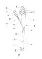
以下、図面に基づいて本発明の実施の形態について説明する。まず、図1に処置具の全体構成を示す。鉗子としては、鉗子作動部がカップ状の生検鉗子、鰐口形状の把持鉗子等があるが、その一例として生検鉗子について説明する。図中において、1は鉗子作動部、2は可撓性コード、3は操作部材であり、これらにより内視鏡用処置具としての鉗子4が構成される。 Hereinafter, embodiments of the present invention will be described with reference to the drawings. First, FIG. 1 shows the overall configuration of the treatment instrument. Examples of the forceps include a biopsy forceps having a cup-like action forceps and a grasping forceps having a shape of a mouth, and the biopsy forceps will be described as an example. In the figure, 1 is a forceps operating portion, 2 is a flexible cord, 3 is an operation member, and these constitute a
鉗子作動部1は、図2に示したように、取付部10に支軸11が設けられており、一対からなるカップ状の鉗子部12,12がこの支軸11を中心として回動可能となっている。そして、これら鉗子部12,12を開閉動作させるために、リンク機構13が設けられ、このリンク機構13を前後動させることによって、鉗子部12,12が開閉動作することになる。 As shown in FIG. 2, the
また、操作部材3は軸部30にスライダ31を、その軸線方向に移動可能に装着したものからなり、軸部30の端部には指掛け部32が連設されており、またスライダ31には円環状溝形状の指掛け部33を備えている。 Further, the operation member 3 is configured by mounting a
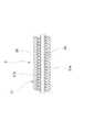
可撓性コード2は、図3及び図4に示したように、挿通路構成体20と回転力伝達スリーブ21との2重管から構成されており、挿通路構成体20の内部に操作ワイヤ22が挿通されている。挿通路構成体20及び回転力伝達スリーブ21は、共にその先端部が鉗子作動部1の取付部10に固定されており、基端部は操作部材3の軸部30に固定して設けられている。一方、操作ワイヤ22の先端はリンク機構13に連結されており、またその基端部はスライダ31に連結されている。 As shown in FIGS. 3 and 4, the
以上のように構成することによって、操作部材3におけるスライダ31を軸部30に沿って図1の矢印方向Fにスライド変位させると、操作ワイヤ22の先端が連結されているリンク機構13が押し出されて、鉗子部12,12が開くようになる。また、スライダ31を図1の矢印R方向にスライド変位させると、操作ワイヤ22が同方向に変位して、リンク機構13が基端側に向けて引き込まれて、鉗子部12,12が閉じることになる。従って、鉗子部12,12を開いた状態で、体内組織を鉗子部12,12間に位置させて、これら鉗子部12,12を閉じることによって、体内組織を切断して回収する等の処置を施すことができるようになる。 With the configuration described above, when the
内視鏡用処置具としての鉗子4は単独で体腔内に挿入されるのではなく、図5に示したように、内視鏡40に挿通させて体腔内に導かれるものである。内視鏡40には、その本体操作部41に処置具導入部42が設けられており、この処置具導入部42から挿入部43の先端に至るように処置具挿通チャンネル44が設けられており、従って処置具はこの処置具挿通チャンネル44に挿通されることになる。 The
内視鏡40において、その挿入部43は本体操作部41への連結側から所定の長さ分が挿入経路に沿って任意の方向に曲る軟性部43aであって、この軟性部43aには湾曲部43bが連設されており、さらに湾曲部43bには先端硬質部43cが連設されている。先端硬質部43cには、照明部及び観察部からなる内視鏡観察手段と共に、処置具を体腔内に導出させる処置具導出部が開口している。 In the
従って、鉗子4の可撓性コード2は曲げ方向に可撓性を有するものである。そして、挿入部43の湾曲部43bは湾曲操作部材45により湾曲されるが、図5に示されているように、例えば180度以上湾曲させることができ、しかも湾曲部43bの長さは短いことから、曲率半径は極めて小さいものとなる。この図5のように湾曲部43bを最大限湾曲させた状態においても、鉗子4は座屈しない構造とする必要がある。また、処置具導入部42における鉗子作動部1の鉗子部12,12で体内組織を把持できるように方向制御できなければならない。 Therefore, the
以上の要請に応じるために、図3及び図4から明らかなように、可撓性コード2は挿通路構成体20と回転力伝達スリーブ21との2重管構造としている。内層としての挿通路構成体20は密巻きコイルから構成される。即ち、金属線材を密着コイル状に巻回したものからなり、内部に操作ワイヤ22を挿通させる通路を構成する。 In order to meet the above requirements, as is apparent from FIGS. 3 and 4, the
また、この密巻きコイルからなる挿通路構成体20に外装されている回転力伝達スリーブ21は、金属細線を編組することにより形成される網状管21aを樹脂チューブ21b内に埋設したものから構成される。そして、樹脂チューブ21bを構成する樹脂はこの網状管21aの編目にも滲み込ませるようにしており、表裏両面は樹脂で覆われて、網状管21aが露出しないようにしている。ここで、回転力伝達スリーブ21は、例えば網状管を内外2層の合成樹脂製のチューブ間に挟み込ませて、加熱しながら加圧することにより形成することができ、また網状管と溶融した樹脂とを一体にしてチューブ状に成形する等により形成することができる。 Moreover, the rotational
このように、2重管構造における内層としての挿通路構成体20と外層としての回転力伝達スリーブ21とは、その全長における大半の部位は非固着状態にして積層させ、その両端における鉗子作動部1の取付部10及び操作部材3の軸部30への連結部は相互に固着されている。従って、この挿通路構成体20と回転力伝達スリーブ21とからなる2重管を曲げたときに、その内外層が相互に摺動可能となっている。 In this way, the
鉗子作動部1と操作部材3との間に設けられる可撓性コード2を以上のように構成することによって、密巻きコイルからなる挿通路構成体20は、その内部における操作ワイヤ22の挿通路が確保される。そして、外部から圧迫を受けても、また処置具挿通チャンネル44内に挿通させた状態で、挿入部43の湾曲部43bを最大限まで湾曲操作したとしても、座屈や変形等が生じることがなく、内部に形成されている挿通路は十分保形され、操作部材3を操作したときに、可撓性コード2の内部に挿通させた操作ワイヤ22が円滑に動作して、鉗子部12,12の開閉動作を円滑に行わせることができる。このように、挿通路構成体20を構成する密巻きコイルは単層構造となっており、外層を構成する回転力伝達スリーブ21は金属細線からなる網状管21aを樹脂チューブ21b内に埋設したものからなり、薄肉のものとして構成できるので、鉗子4の可撓性コード2の細径化が可能になる。 By configuring the
鉗子4を挿入部43の先端から導出させた状態で、その鉗子作動部1における鉗子部12,12の方向を制御するためには、鉗子4のうち処置具導入部42から外部に位置する部位の可撓性コード2または操作部材3を捻るようにして軸回りに回転させる。可撓性コード2は、樹脂チューブ21bに埋設された網状管21aからなる回転力伝達スリーブ21から構成されているので、処置具導入部42の外部から可撓性コード2に回転力を与えると、処置具挿通チャンネル44内で軸回りに回転して、先端の鉗子作動部1を所望の角度分だけ回転させることができる。この回転力は回転力伝達スリーブ21により正確に伝達され、しかも応答性が良好となる。ここで、回転力伝達スリーブ21の内層として密巻きコイルからなる挿通路構成体20が配置されているが、この密巻きコイルには遊びがあるのに対して、前述したように回転力伝達スリーブ21における回転伝達の応答性が高く、しかも挿通路構成体20は回転力伝達スリーブ21と固着関係にはないので、挿通路構成体20に回転力が作用することはない。 In order to control the direction of the
さらに、可撓性コード2における挿通路構成体20及び回転力伝達スリーブ21は共に曲げ方向における可撓性を有するものであるから、可撓性コード2を自由に曲げることができる。しかも、2重構造となっている挿通路構成体20と回転力伝達スリーブ21とは相互に固着されていないので、可撓性コード2における曲げに対する抵抗はこれら両部材が加重的に作用するものではなく、いずれか曲げに対する抵抗が大きい方のもの、一般に挿通路構成体20を構成する単層からなる密巻きコイルの方が曲げに対する抵抗が小さいために、実質的に回転力伝達スリーブ21の曲げに対する抵抗力のみが作用することになる。従って、内視鏡40の挿入部43における湾曲部43bが図5に示したように、大きく湾曲している状態でも、鉗子4を円滑に処置具挿通チャンネル44内に挿通させて、先端硬質部43cから導出させることができる。従って、鉗子4の内視鏡40の処置具挿通チャンネル44への挿通操作性が良好となる。 Furthermore, since both the
そして、可撓性コード2において、外部に露出しているのは樹脂チューブ21bからなる回転力伝達スリーブ21であり、この樹脂チューブ21bを滑りの良い部材で形成することによって、処置具挿通チャンネル44への挿通をさらに円滑に行うことができる。また、可撓性コード2が曲げられたときに、樹脂チューブ21bと挿通路構成体20との間が円滑に滑るようにもなり、従って曲げに対する抵抗がさらに小さくなる。 In the
1 鉗子作動部 2 可撓性コード
3 操作部材 4 鉗子
12 鉗子部 20 挿通路構成体
21 回転力伝達スリーブ 21a 網状管
21b 樹脂チューブ 22 操作ワイヤ
30 軸部 31 スライダ
40 内視鏡 42 処置具導入部
43 挿入部 44 処置具挿通チャンネルDESCRIPTION OF
Claims (1)
Translated fromJapanese前記可撓性コードは、挿通路構成体と回転力伝達スリーブとの2重の管状部材から構成され、
前記挿通路構成体は密巻きコイルからなり、また前記回転力伝達スリーブは樹脂チューブに網状管を埋設させたものからなり、
前記挿通路構成体は前記回転力伝達スリーブ内に相対摺動可能に挿嵌させて設け、前記操作ワイヤは前記挿通路構成管内に挿通させる
構成としたことを特徴とする内視鏡用処置具。An operating portion is provided at the distal end of the flexible cord, an operation wire for operating the operating portion is inserted into the flexible cord, and the operation wire is operated at a base end portion of the flexible cord. In the endoscope treatment tool provided with means and inserted into the treatment tool insertion channel of the endoscope,
The flexible cord is composed of a double tubular member of an insertion path structure and a rotational force transmission sleeve,
The insertion passage structure is formed by a closely wound coil, and the rotational force transmission sleeve is formed by embedding a mesh tube in a resin tube,
The endoscope treatment tool characterized in that the insertion passage structure is provided so as to be relatively slidably inserted into the rotational force transmission sleeve, and the operation wire is inserted into the insertion passage structure tube. .
Priority Applications (8)
| Application Number | Priority Date | Filing Date | Title |
|---|---|---|---|
| JP2007078266AJP2008237266A (en) | 2007-03-26 | 2007-03-26 | Endoscopic treatment instrument |
| CN2008100058045ACN101273914B (en) | 2007-03-26 | 2008-02-05 | Endoscopic treatment tool |
| US12/029,673US20080242924A1 (en) | 2007-03-26 | 2008-02-12 | Endoscopic treatment tool |
| EP08002573AEP1974675B1 (en) | 2007-03-26 | 2008-02-12 | Endoscopic treatment tool |
| DE602008000391TDE602008000391D1 (en) | 2007-03-26 | 2008-02-12 | Endoscopic treatment tool |
| KR1020080012619AKR101018365B1 (en) | 2007-03-26 | 2008-02-12 | Endoscopic treatment tools |
| AT08002573TATE451875T1 (en) | 2007-03-26 | 2008-02-12 | ENDOSCOPIC TREATMENT TOOL |
| TW097104988ATW200838470A (en) | 2007-03-26 | 2008-02-13 | Endoscopic treatment tool |
Applications Claiming Priority (1)
| Application Number | Priority Date | Filing Date | Title |
|---|---|---|---|
| JP2007078266AJP2008237266A (en) | 2007-03-26 | 2007-03-26 | Endoscopic treatment instrument |
Publications (1)
| Publication Number | Publication Date |
|---|---|
| JP2008237266Atrue JP2008237266A (en) | 2008-10-09 |
Family
ID=39495137
Family Applications (1)
| Application Number | Title | Priority Date | Filing Date |
|---|---|---|---|
| JP2007078266AAbandonedJP2008237266A (en) | 2007-03-26 | 2007-03-26 | Endoscopic treatment instrument |
Country Status (8)
| Country | Link |
|---|---|
| US (1) | US20080242924A1 (en) |
| EP (1) | EP1974675B1 (en) |
| JP (1) | JP2008237266A (en) |
| KR (1) | KR101018365B1 (en) |
| CN (1) | CN101273914B (en) |
| AT (1) | ATE451875T1 (en) |
| DE (1) | DE602008000391D1 (en) |
| TW (1) | TW200838470A (en) |
Cited By (2)
| Publication number | Priority date | Publication date | Assignee | Title |
|---|---|---|---|---|
| WO2010106714A1 (en)* | 2009-03-18 | 2010-09-23 | オリンパスメディカルシステムズ株式会社 | Treatment device for endoscope |
| WO2013038779A1 (en)* | 2011-09-15 | 2013-03-21 | 富士フイルム株式会社 | Medical treatment instrument |
Families Citing this family (10)
| Publication number | Priority date | Publication date | Assignee | Title |
|---|---|---|---|---|
| US20100087711A1 (en)* | 2008-10-06 | 2010-04-08 | Gyrus Ent, L.L.C. | Repeatably flexible surgical instrument |
| KR101298690B1 (en)* | 2011-01-25 | 2013-08-21 | 신경민 | Medical Snare |
| US9204868B2 (en) | 2011-12-02 | 2015-12-08 | Interscope, Inc. | Methods and apparatus for removing material from within a mammalian cavity using an insertable endoscopic instrument |
| US8882680B2 (en) | 2011-12-02 | 2014-11-11 | Interscope, Inc. | Insertable endoscopic instrument for tissue removal |
| CN103142257B (en)* | 2013-03-29 | 2016-01-06 | 张亦范 | Electronic endoscope apparatus |
| EP3513747A1 (en)* | 2013-05-17 | 2019-07-24 | Interscope, Inc. | Insertable endoscopic instrument for tissue removal |
| WO2018073951A1 (en)* | 2016-10-21 | 2018-04-26 | オリンパス株式会社 | Treatment tool rotation mechanism |
| WO2018185917A1 (en)* | 2017-04-06 | 2018-10-11 | 朝日インテック株式会社 | Tubular body and tubular body having catheter |
| JP2018201765A (en)* | 2017-06-01 | 2018-12-27 | オリンパス株式会社 | Tube for medical equipment |
| CN109498149B (en)* | 2018-12-27 | 2024-03-29 | 北京术锐机器人股份有限公司 | Surgical tool |
Citations (9)
| Publication number | Priority date | Publication date | Assignee | Title |
|---|---|---|---|---|
| JPS57195434A (en)* | 1981-05-28 | 1982-12-01 | Olympus Optical Co | Flexible pipe of endoscope |
| US4945920A (en)* | 1988-03-28 | 1990-08-07 | Cordis Corporation | Torqueable and formable biopsy forceps |
| JPH04183478A (en)* | 1990-11-20 | 1992-06-30 | Mitsubishi Cable Ind Ltd | Medical tubular body |
| JPH10277047A (en)* | 1997-04-09 | 1998-10-20 | Olympus Optical Co Ltd | Treating implement for endoscope |
| JPH11104071A (en)* | 1997-08-05 | 1999-04-20 | Olympus Optical Co Ltd | Treating instrument for endoscope |
| JP2000060794A (en)* | 1998-08-18 | 2000-02-29 | Mitsubishi Cable Ind Ltd | Torque transmitting tube and endoscope |
| JP2001321386A (en)* | 2000-05-17 | 2001-11-20 | Olympus Optical Co Ltd | Operating tool for endoscope |
| JP2002253563A (en)* | 2001-03-02 | 2002-09-10 | Olympus Optical Co Ltd | Treatment instrument for endoscope |
| JP2005034623A (en)* | 2003-06-24 | 2005-02-10 | Olympus Corp | Treatment tool for endoscope |
Family Cites Families (12)
| Publication number | Priority date | Publication date | Assignee | Title |
|---|---|---|---|---|
| US3964468A (en)* | 1975-05-30 | 1976-06-22 | The Board Of Trustees Of Leland Stanford Junior University | Bioptome |
| FR2582504A1 (en)* | 1985-06-04 | 1986-12-05 | Schintgen Jean Marie | IMPROVEMENTS ON BIOPSY CLAMPS |
| US5035248A (en)* | 1987-04-23 | 1991-07-30 | Zinnecker Hal P | Polyolefin sheath and silicone O-ring for medical instrument |
| IT1211530B (en)* | 1987-11-16 | 1989-11-03 | Consiglio Nazionale Ricerche | AREA OF THE POINT OF ORIGIN OF ARITCATERERE FOR ENDOCARDIC BIOPSY AND MY VENTRICULARS THAT CAN BE USED ALSO FOR THE INDIVIDUAL |
| US5094247A (en)* | 1990-08-31 | 1992-03-10 | Cordis Corporation | Biopsy forceps with handle having a flexible coupling |
| US5254130A (en)* | 1992-04-13 | 1993-10-19 | Raychem Corporation | Surgical device |
| US5318528A (en)* | 1993-04-13 | 1994-06-07 | Advanced Surgical Inc. | Steerable surgical devices |
| US5904647A (en)* | 1996-10-08 | 1999-05-18 | Asahi Kogyo Kabushiki Kaisha | Treatment accessories for an endoscope |
| JP3417778B2 (en) | 1997-01-17 | 2003-06-16 | ペンタックス株式会社 | Endoscope treatment tool |
| JP2000175928A (en)* | 1998-10-08 | 2000-06-27 | Olympus Optical Co Ltd | Treating implement for endoscope |
| JP3634655B2 (en) | 1999-02-09 | 2005-03-30 | ペンタックス株式会社 | Endoscopic biopsy forceps |
| JP4046981B2 (en)* | 2001-11-13 | 2008-02-13 | ペンタックス株式会社 | Endoscopic clip device |
- 2007
- 2007-03-26JPJP2007078266Apatent/JP2008237266A/ennot_activeAbandoned
- 2008
- 2008-02-05CNCN2008100058045Apatent/CN101273914B/ennot_activeExpired - Fee Related
- 2008-02-12DEDE602008000391Tpatent/DE602008000391D1/enactiveActive
- 2008-02-12USUS12/029,673patent/US20080242924A1/ennot_activeAbandoned
- 2008-02-12KRKR1020080012619Apatent/KR101018365B1/ennot_activeExpired - Fee Related
- 2008-02-12EPEP08002573Apatent/EP1974675B1/ennot_activeNot-in-force
- 2008-02-12ATAT08002573Tpatent/ATE451875T1/ennot_activeIP Right Cessation
- 2008-02-13TWTW097104988Apatent/TW200838470A/enunknown
Patent Citations (9)
| Publication number | Priority date | Publication date | Assignee | Title |
|---|---|---|---|---|
| JPS57195434A (en)* | 1981-05-28 | 1982-12-01 | Olympus Optical Co | Flexible pipe of endoscope |
| US4945920A (en)* | 1988-03-28 | 1990-08-07 | Cordis Corporation | Torqueable and formable biopsy forceps |
| JPH04183478A (en)* | 1990-11-20 | 1992-06-30 | Mitsubishi Cable Ind Ltd | Medical tubular body |
| JPH10277047A (en)* | 1997-04-09 | 1998-10-20 | Olympus Optical Co Ltd | Treating implement for endoscope |
| JPH11104071A (en)* | 1997-08-05 | 1999-04-20 | Olympus Optical Co Ltd | Treating instrument for endoscope |
| JP2000060794A (en)* | 1998-08-18 | 2000-02-29 | Mitsubishi Cable Ind Ltd | Torque transmitting tube and endoscope |
| JP2001321386A (en)* | 2000-05-17 | 2001-11-20 | Olympus Optical Co Ltd | Operating tool for endoscope |
| JP2002253563A (en)* | 2001-03-02 | 2002-09-10 | Olympus Optical Co Ltd | Treatment instrument for endoscope |
| JP2005034623A (en)* | 2003-06-24 | 2005-02-10 | Olympus Corp | Treatment tool for endoscope |
Cited By (5)
| Publication number | Priority date | Publication date | Assignee | Title |
|---|---|---|---|---|
| WO2010106714A1 (en)* | 2009-03-18 | 2010-09-23 | オリンパスメディカルシステムズ株式会社 | Treatment device for endoscope |
| JP4659145B2 (en)* | 2009-03-18 | 2011-03-30 | オリンパスメディカルシステムズ株式会社 | Endoscopic treatment tool |
| US8974492B2 (en) | 2009-03-18 | 2015-03-10 | Olympus Medical Systems Corp. | Endoscopic treatment tool |
| WO2013038779A1 (en)* | 2011-09-15 | 2013-03-21 | 富士フイルム株式会社 | Medical treatment instrument |
| JP2013063106A (en)* | 2011-09-15 | 2013-04-11 | Fujifilm Corp | Medical treatment instrument |
Also Published As
| Publication number | Publication date |
|---|---|
| TW200838470A (en) | 2008-10-01 |
| KR20080087651A (en) | 2008-10-01 |
| DE602008000391D1 (en) | 2010-01-28 |
| CN101273914A (en) | 2008-10-01 |
| KR101018365B1 (en) | 2011-03-04 |
| EP1974675B1 (en) | 2009-12-16 |
| CN101273914B (en) | 2011-06-15 |
| EP1974675A1 (en) | 2008-10-01 |
| ATE451875T1 (en) | 2010-01-15 |
| US20080242924A1 (en) | 2008-10-02 |
Similar Documents
| Publication | Publication Date | Title |
|---|---|---|
| JP2008237266A (en) | Endoscopic treatment instrument | |
| US6015381A (en) | Endoscopic treatment tool | |
| CN201150526Y (en) | Treating apparatus for endoscope | |
| US9872607B2 (en) | Endoscope | |
| CN201131730Y (en) | Endoscope Treatment Instruments | |
| JP6482101B2 (en) | Operation unit for bending treatment tools | |
| JP6280848B2 (en) | Medical instruments | |
| US20250151987A1 (en) | Endoscope treatment tool and endoscope system | |
| JP6180694B2 (en) | Suture device | |
| JP4517126B2 (en) | Endoscopic treatment tool | |
| JP2009112537A (en) | Flexible endoscope | |
| JP5160798B2 (en) | Endoscope, its bending operation strip, and manufacturing method of endoscope | |
| WO2016166830A1 (en) | Hinge member for bendable treatment tool and bendable treatment tool having said hinge member incorporated therein | |
| JP2007260248A (en) | Treatment implement for endoscope | |
| EP1875872A1 (en) | Treatment instrument for endoscope | |
| JP6284182B2 (en) | Operation unit for bending treatment tools | |
| JP6637991B2 (en) | Medical equipment | |
| WO2012090859A1 (en) | Treatment instrument for endoscopes | |
| JP2010104668A (en) | Endoscope flexible part, endoscope, and method of manufacturing endoscope flexible part | |
| CN108348138A (en) | Endoscope with a detachable handle | |
| JP4151920B2 (en) | Endoscopic treatment tool | |
| JP2015128534A (en) | Hinge member for bending treatment tool and bending treatment tool incorporating the hinge member | |
| JP6157334B2 (en) | Insertion equipment | |
| JP6402285B1 (en) | Endoscope | |
| JP2021087519A (en) | Treatment instrument for endoscope |
Legal Events
| Date | Code | Title | Description |
|---|---|---|---|
| A621 | Written request for application examination | Free format text:JAPANESE INTERMEDIATE CODE: A621 Effective date:20090911 | |
| A711 | Notification of change in applicant | Free format text:JAPANESE INTERMEDIATE CODE: A711 Effective date:20091009 | |
| A977 | Report on retrieval | Free format text:JAPANESE INTERMEDIATE CODE: A971007 Effective date:20111004 | |
| A131 | Notification of reasons for refusal | Free format text:JAPANESE INTERMEDIATE CODE: A131 Effective date:20111025 | |
| A762 | Written abandonment of application | Free format text:JAPANESE INTERMEDIATE CODE: A762 Effective date:20120105 |