JP2008232207A - Disk brake pad for bicycle - Google Patents
Disk brake pad for bicycleDownload PDFInfo
- Publication number
- JP2008232207A JP2008232207AJP2007070249AJP2007070249AJP2008232207AJP 2008232207 AJP2008232207 AJP 2008232207AJP 2007070249 AJP2007070249 AJP 2007070249AJP 2007070249 AJP2007070249 AJP 2007070249AJP 2008232207 AJP2008232207 AJP 2008232207A
- Authority
- JP
- Japan
- Prior art keywords
- back plate
- brake pad
- friction
- bicycle
- copper
- Prior art date
- Legal status (The legal status is an assumption and is not a legal conclusion. Google has not performed a legal analysis and makes no representation as to the accuracy of the status listed.)
- Pending
Links
- 239000010949copperSubstances0.000claimsabstractdescription37
- RYGMFSIKBFXOCR-UHFFFAOYSA-NCopperChemical compound[Cu]RYGMFSIKBFXOCR-UHFFFAOYSA-N0.000claimsabstractdescription33
- 229910052802copperInorganic materials0.000claimsabstractdescription33
- 229910045601alloyInorganic materials0.000claimsabstractdescription13
- 239000000956alloySubstances0.000claimsabstractdescription13
- 229910052751metalInorganic materials0.000claimsdescription19
- 239000002184metalSubstances0.000claimsdescription19
- ATJFFYVFTNAWJD-UHFFFAOYSA-NTinChemical compound[Sn]ATJFFYVFTNAWJD-UHFFFAOYSA-N0.000claimsdescription15
- 239000000843powderSubstances0.000claimsdescription14
- 238000005245sinteringMethods0.000claimsdescription9
- 239000011651chromiumSubstances0.000claimsdescription8
- XEEYBQQBJWHFJM-UHFFFAOYSA-NIronChemical compound[Fe]XEEYBQQBJWHFJM-UHFFFAOYSA-N0.000claimsdescription6
- VYZAMTAEIAYCRO-UHFFFAOYSA-NChromiumChemical compound[Cr]VYZAMTAEIAYCRO-UHFFFAOYSA-N0.000claimsdescription4
- 229910052804chromiumInorganic materials0.000claimsdescription4
- 238000000465mouldingMethods0.000claimsdescription4
- 238000004519manufacturing processMethods0.000abstractdescription9
- 238000007747platingMethods0.000description10
- 238000009792diffusion processMethods0.000description8
- 238000000034methodMethods0.000description7
- 238000010438heat treatmentMethods0.000description5
- 239000000203mixtureSubstances0.000description4
- PXHVJJICTQNCMI-UHFFFAOYSA-NNickelChemical compound[Ni]PXHVJJICTQNCMI-UHFFFAOYSA-N0.000description3
- 238000010586diagramMethods0.000description3
- 238000005304joiningMethods0.000description3
- 150000001875compoundsChemical class0.000description2
- 239000000463materialSubstances0.000description2
- 238000002156mixingMethods0.000description2
- 229910000838Al alloyInorganic materials0.000description1
- OKTJSMMVPCPJKN-UHFFFAOYSA-NCarbonChemical compound[C]OKTJSMMVPCPJKN-UHFFFAOYSA-N0.000description1
- 241000357293Leptobrama muelleriSpecies0.000description1
- 239000004020conductorSubstances0.000description1
- QDOXWKRWXJOMAK-UHFFFAOYSA-Ndichromium trioxideChemical compoundO=[Cr]O[Cr]=OQDOXWKRWXJOMAK-UHFFFAOYSA-N0.000description1
- 238000010304firingMethods0.000description1
- 239000012530fluidSubstances0.000description1
- PCHJSUWPFVWCPO-UHFFFAOYSA-NgoldChemical compound[Au]PCHJSUWPFVWCPO-UHFFFAOYSA-N0.000description1
- 239000010931goldSubstances0.000description1
- 229910052737goldInorganic materials0.000description1
- 229910002804graphiteInorganic materials0.000description1
- 239000010439graphiteSubstances0.000description1
- 229910052742ironInorganic materials0.000description1
- 150000002739metalsChemical class0.000description1
- 229910052759nickelInorganic materials0.000description1
- 230000002093peripheral effectEffects0.000description1
- 238000003825pressingMethods0.000description1
- 238000002203pretreatmentMethods0.000description1
- 239000000126substanceSubstances0.000description1
- 239000000725suspensionSubstances0.000description1
Images


Classifications
- F—MECHANICAL ENGINEERING; LIGHTING; HEATING; WEAPONS; BLASTING
- F16—ENGINEERING ELEMENTS AND UNITS; GENERAL MEASURES FOR PRODUCING AND MAINTAINING EFFECTIVE FUNCTIONING OF MACHINES OR INSTALLATIONS; THERMAL INSULATION IN GENERAL
- F16D—COUPLINGS FOR TRANSMITTING ROTATION; CLUTCHES; BRAKES
- F16D65/00—Parts or details
- F16D65/02—Braking members; Mounting thereof
- F16D65/04—Bands, shoes or pads; Pivots or supporting members therefor
- F16D65/092—Bands, shoes or pads; Pivots or supporting members therefor for axially-engaging brakes, e.g. disc brakes
- F—MECHANICAL ENGINEERING; LIGHTING; HEATING; WEAPONS; BLASTING
- F16—ENGINEERING ELEMENTS AND UNITS; GENERAL MEASURES FOR PRODUCING AND MAINTAINING EFFECTIVE FUNCTIONING OF MACHINES OR INSTALLATIONS; THERMAL INSULATION IN GENERAL
- F16D—COUPLINGS FOR TRANSMITTING ROTATION; CLUTCHES; BRAKES
- F16D69/00—Friction linings; Attachment thereof; Selection of coacting friction substances or surfaces
- F16D69/02—Composition of linings ; Methods of manufacturing
- F16D69/027—Compositions based on metals or inorganic oxides
- F—MECHANICAL ENGINEERING; LIGHTING; HEATING; WEAPONS; BLASTING
- F16—ENGINEERING ELEMENTS AND UNITS; GENERAL MEASURES FOR PRODUCING AND MAINTAINING EFFECTIVE FUNCTIONING OF MACHINES OR INSTALLATIONS; THERMAL INSULATION IN GENERAL
- F16D—COUPLINGS FOR TRANSMITTING ROTATION; CLUTCHES; BRAKES
- F16D69/00—Friction linings; Attachment thereof; Selection of coacting friction substances or surfaces
- F16D2069/001—Material of friction lining and support element of same or similar composition
Landscapes
- Engineering & Computer Science (AREA)
- General Engineering & Computer Science (AREA)
- Mechanical Engineering (AREA)
- Chemical & Material Sciences (AREA)
- Inorganic Chemistry (AREA)
- Braking Arrangements (AREA)
- Powder Metallurgy (AREA)
Abstract
Description
Translated fromJapanese本発明は、ブレーキパッド、特に、自転車用ディスクブレーキ装置のディスクブレーキパッドに関する。 The present invention relates to a brake pad, and more particularly to a disc brake pad of a bicycle disc brake device.
ディスクブレーキパッドは、通常、車輪とともに回転するディスクブレーキロータを挟持して車輪を制動する。この種のディスクブレーキパッドとして、銅系焼結金属製の乾式の摩擦部材と、摩擦部材が接合されたたとえばステンレス合金等の鋼製のバックプレートとを有するものが従来周知である(たとえば、特許文献1参照)。このような焼結金属製の摩擦部材を有する従来のディスクブレーキパッドでは、摩擦部材は拡散接合法によって焼結金属の焼成と、バックプレートへの接合とを同時に行って製造している。具体的には、バックプレートの接合面に銅めっきを形成し、その銅めっき層の上に摩擦部材となる成形された金属粉末の圧粉体を載置し、たとえば、900℃程度の高温で加熱プレス機により摩擦部材となる圧粉体を焼成しつつバックプレートに接合している。このように製造されたブレーキパッドでは、バックプレートと銅めっき層とは金属的に結合する化学結合により結合されている。
前記従来の銅めっき層上に摩擦部材を拡散接合法により接合する構成では、摩擦部材に化学的に結合する銅めっき層をバックプレート上に形成し、その上に摩擦部材を焼結形成している。このため、バックプレート表面に銅めっき層を形成する前処理工程や熱処理中に加圧して拡散接合するための設備が必要になり、製造工程が複雑になる。 In the configuration in which the friction member is bonded to the conventional copper plating layer by a diffusion bonding method, a copper plating layer chemically bonded to the friction member is formed on the back plate, and the friction member is formed on the back plate by sintering. Yes. This necessitates a pretreatment process for forming a copper plating layer on the surface of the back plate and a facility for pressurizing and diffusion bonding during heat treatment, which complicates the manufacturing process.
また、拡散接合するには、850度以上の高い温度が必要であり、焼結の際の焼成温度が高くなって摩擦部材の硬度が高くなり、制動時に音鳴りすることがある。 Further, for diffusion bonding, a high temperature of 850 ° C. or higher is required, and the firing temperature during sintering becomes high, the hardness of the friction member becomes high, and noise may occur during braking.
本発明の課題は、自転車用ディスクブレーキパッドにおいて、音鳴りを抑え、かつ製造を容易に行えるようにすることにある。 SUMMARY OF THE INVENTION An object of the present invention is to provide a bicycle disc brake pad that suppresses noise and can be easily manufactured.
発明1に係る自転車用ディスクブレーキパッドは、自転車用ディスクブレーキ装置のディスクブレーキパッドであって、バックプレート部と、摩擦部と、を備えている。バックプレート部は、銅系焼結合金製のものである。摩擦部は、バックプレート部と一体で焼結形成された銅系焼結合金製のものである。 A bicycle disc brake pad according to a first aspect is a disc brake pad of a bicycle disc brake device, and includes a back plate portion and a friction portion. The back plate portion is made of a copper-based sintered alloy. The friction portion is made of a copper-based sintered alloy that is integrally sintered with the back plate portion.
このディスクブレーキパッドでは、従来は摩擦部にしか使用されていない銅系焼結合金でバックプレート部を摩擦部と一体で成形し焼結形成している。このため、従来、摩擦部材に化学的に結合する銅めっき層をバックプレート上に形成し、その上に摩擦部材を焼結形成している工程に比べて、銅めっき層を形成する前処理工程や熱処理中に加圧して拡散接合する工程が不要になる。しかも、バックプレートに摩擦部を接合する必要がないため、接合のための温度より低い温度で摩擦部を含むブレーキパッドを製造可能になる。この結果、摩擦部の硬度が低くなり、音鳴りを抑えることができるとともに、自転車用ディスクブレーキパッドの製造工程を簡素化して製造を容易に行えるようになる。 In this disc brake pad, the back plate portion is formed integrally with the friction portion and sintered by a copper-based sintered alloy that is conventionally used only for the friction portion. For this reason, the pretreatment process which forms a copper plating layer conventionally compared with the process which forms the copper plating layer chemically bonded to a friction member on a backplate, and sinters the friction member on it. And a step of performing diffusion bonding by applying pressure during heat treatment is not necessary. And since it is not necessary to join a friction part to a backplate, it becomes possible to manufacture the brake pad containing a friction part at the temperature lower than the temperature for joining. As a result, the hardness of the friction portion is reduced, and noise can be suppressed, and the manufacturing process of the bicycle disc brake pad can be simplified and can be easily manufactured.
発明2に係る自転車用ディスクブレーキパッドは、発明1に記載のパッドにおいて、バックプレート部及び摩擦部は、銅及び錫を含む金属粉末を成形して共に一体焼結させて製造される。この場合には、銅に錫を加えることにより、バックプレートとしての強度を維持して摩擦部としての耐熱性や耐摩耗性を維持できる。 A bicycle disc brake pad according to a second aspect of the present invention is the pad according to the first aspect, wherein the back plate portion and the friction portion are manufactured by molding metal powder containing copper and tin and sintering them together. In this case, by adding tin to copper, the strength as the back plate can be maintained, and the heat resistance and wear resistance as the friction portion can be maintained.
発明3に係る自転車用ディスクブレーキパッドは、発明2に記載のパッドにおいて、バックプレート部の金属粉末は、重量比で銅(Cu)が約89パーセント、錫(Sn)が約9パーセント、鉄(Fe)及びクロム(Cr)がそれぞれ約1パーセントである、この場合には、錫の割合を多くすることによりによりバックプレートの強度を高めることができる。 A bicycle disc brake pad according to a third aspect of the present invention is the pad according to the second aspect, wherein the metal powder in the back plate portion is about 89 percent copper (Cu), about 9 percent tin (Sn), and iron (by weight). Fe) and chromium (Cr) are each about 1 percent. In this case, the strength of the back plate can be increased by increasing the proportion of tin.
本発明によれば、従来、摩擦部材に化学的に結合する銅めっき層をバックプレート上に形成し、その上に摩擦部材を焼結形成している工程に比べて、銅めっき層を形成する前処理工程や熱処理中に加圧して拡散接合する工程が不要になる。しかも、バックプレートに摩擦部を接合する必要がないため、接合のための温度より低い温度で摩擦部を含むブレーキパッドを製造可能になる。この結果、摩擦部の硬度が低くなり、音鳴りを抑えることができるとともに、自転車用ディスクブレーキパッドの製造工程を簡素化して製造を容易に行えるようになる。 According to the present invention, conventionally, a copper plating layer that is chemically bonded to the friction member is formed on the back plate, and the copper plating layer is formed as compared with the step of sintering the friction member thereon. There is no need for a pre-treatment step or a step of performing pressure diffusion bonding during heat treatment. And since it is not necessary to join a friction part to a backplate, it becomes possible to manufacture the brake pad containing a friction part at the temperature lower than the temperature for joining. As a result, the hardness of the friction portion is reduced, and noise can be suppressed, and the manufacturing process of the bicycle disc brake pad can be simplified and can be easily manufactured.
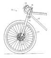
図1は、本発明の実施形態1によるディスクブレーキ装置12を搭載した自転車10のフロント部分を示している。このような自転車10は、当該技術では公知であり、自転車の構成部品についての詳細な説明は省略する。 FIG. 1 shows a front portion of a
自転車10は、従来知られたものであり、ハンドルバー15を有する自転車フレーム14と、フロント及びリアフォーク16(フロントフォークのみ図示)と、前後輪17(前輪のみ図示)と、スプロケットやチェーンを含む駆動装置とを含んでいる。 The
ディスクブレーキ装置12は、ダブルクラウン型のサスペンション付きのフロントフォーク16に装着されたブレーキキャリパ21と、ディスクロータ22と、ブレーキ作動機構23とを備えている。 The
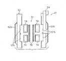
ブレーキキャリパ21は、ディスクロータ22に近接した位置で自転車10のフロントフォーク16に取り付けられており、ディスクロータ22にその回転を停止させる締め付け力を加えることができる。図2及び図3に示すように、ブレーキキャリパ21は、ハウジング50と、ピストンユニット51とを備えている。ハウジング50は、たとえばアルミニウム合金などの熱伝導性材料で構成されており、ボルトで結合された第1ハウジング部材52aと、第2ハウジング部材52bとを有している。両ハウジング部材52a,52bは実質的に同じ形状であり、第2ハウジング部材52bには、ブレーキ作動機構23の油圧配管86が連結され、両ハウジング部材52a,52bにブレーキオイルが供給されるようになっている。 The
また、第2ハウジング部材52bは、ブレーキキャリパ21をフロントフォーク16にボルト止めするための取付部材54を形成する外向きに延出したフランジを有している。両ハウジング部材52a,52bをボルト締めすると、ブレーキスロットがその間に形成され、その間にディスクロータ22を収納することができる。また両ハウジング部材52a,52bには、図3及び図5に示すように、それぞれ2つのピストン74が収納される円形のシリンダ部57a,57bと、それぞれのシリンダ部57a,57bにブレーキオイルを供給するための油路58a,58bが形成されている。これにより、ブレーキ作動機構23から供給されたブレーキオイルは、第2ハウジング部材52bに流入して油路58a,58bに流入することによってピストンユニット51を作動させる。 Further, the
図3に示すように、ピストンユニット51は、4つのピストン74と、1対のブレーキパッド76とを有している。ピストン74は、1対のシリンダ部57a,57bに摺動自在にはめ込まれており、制動解除位置と制動位置との間で移動する。ブレーキパッド76は、ピストン74の先端に配置され一体で移動する。したがって、ピストン74が制動解除位置から制動位置に移動するとブレーキパッド76も制動解除位置から制動位置に移動する。制動位置にあるとき、ブレーキパッド76はディスクロータ22を挟持して摩擦係合し、ディスクロータ22を介して前輪17を制動する。制動解除位置にあるとき、ブレーキパッド76はディスクロータ22から離れてディスクロータ22は自由回転可能になる。 As shown in FIG. 3, the
ブレーキパッド76は、たとえば、全体が焼結合金製の焼結パッドであり、図6及び図7に示すように、たとえば、バックプレート部77と、バックプレート部77上に形成された摩擦部79とを備えている。 The
バックプレート部77は、たとえば、1.7mm〜1.8mm程度の厚みの銅系焼結金製の板状部分であり、第1及び第2ハウジング部材52a,52bに係止される鉤状の係止部77aと、第1及び第2ハウジング部材52a,52bに進退自在に支持される円形の支持部77bとを有している。バックプレート部77は、銅及び錫を含む金属粉末を成型して焼結させて製造される。バックプレート部77に用いる金属粉末は、重量比で銅(Cu)が約89パーセント、錫(Sn)が約9パーセント、鉄(Fe)及びクロム(Cr)がそれぞれ約1パーセントである。 The
摩擦部79は、バックプレート部77と、一体で焼結形成された銅系焼結合金製である。バックプレート部77及び摩擦部79は、銅及び錫を含む金属粉末を成形して共に一体焼結させて製造される。摩擦部79の厚みは、たとえば、2.0mm〜2.5mm程度の厚みである。摩擦部79の金属粉末は、摩擦部79の金属粉末は、重量比で銅(Cu)が約60パーセント、錫(Sn)が約2パーセント、鉛(Zn)が約7パーセント、ニッケル(Ni)が約6パーセント、クロム(Cr)が約3パーセント、鉄(Fe)が約2パーセント、黒鉛が約10パーセント、その他の金属が約10パーセント程度である。 The
このようにバックプレート部77と摩擦部79とで同じ銅系焼結合金であっても、銅と錫の重量比を変え、バックプレート部77の錫の割合を多くすることにより、バックプレート部77に要求される高い強度と、摩擦部79に要求される耐熱性や耐摩耗性を高めることができる。 Thus, even if the
次にディスクブレーキパッド76の製造方法について説明する。 Next, a method for manufacturing the
最初にバックプレート部77と摩擦部79とで配合割合を変えた2種の金属粉末の混合物を用意する。配合割合は前述したとおりである。次に、図6及び図7に示したような形状のブレーキパッド76となる空間が形成された金型に金属粉末の混合物を充填する。この充填工程では、最初に、用意された摩擦部79用の金属粉末の混合物を金型の摩擦部となる空間に充填し、続いて、バックプレート部77用の金属粉末の混合物をバックプレート部となる空間に充填する。充填が終わると、ブレス用の金型で空間を塞いで加熱プレス機にセットする。そして、プレス機で、たとえば800℃の温度でプレス加工して所望の形状に焼結成形する。これにより、摩擦部79とバックプレート部77とが一体で形成されたブレーキパッド76が形成される。 First, a mixture of two kinds of metal powders in which the mixing ratio is changed between the
ここでは、錫を含む銅系焼結金属製のバックプレート部77と摩擦部79とが一体形成されるので、ブレーキパッドの製造工程が簡素化し、ブレーキパッドのコストダウンを図ることができる。 Here, the
また、拡散接合により摩擦部を接合する必要がないので、焼結温度を低くすることができ、摩擦部79の硬度を低くできる。このため、制動時に摩擦部79がディスクロータ22を挟持しても、音鳴りが生じにくくなる。 In addition, since it is not necessary to join the friction part by diffusion bonding, the sintering temperature can be lowered and the hardness of the
さらに、ブレーキバッド76全体を圧粉成形するので、複雑な三次元形状のバックプレートの製作も容易になり、機能及び意匠の向上を図ることもできる。 Furthermore, since the
ディスクロータ22は、図1に示すように、前輪17のハブに固定されており、前輪17に連動して回転する。ディスクロータ22は、図2に示すように、たとえばステンレス合金製の円板部材であり、中心に位置するハブ取付部22aと外周側の摩擦面となるリング状のロータ部22bとを一体形成したものである。 As shown in FIG. 1, the
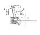
ブレーキ作動機構23は、図4及び図5に示すように、ブレーキキャリパ21を作動させてディスクロータ22を強力に挟持することにより前輪17に制動をかけるための機構である。ブレーキ作動機構23は、ハンドルバー15の右端部に一体で取り付けられている。ブレーキ作動機構23は、ブレーキレバー80と、マスターシリンダ81と、マスターピストン82と、オイルタンク83とを有している。 As shown in FIGS. 4 and 5, the
ブレーキレバー80は、図4及び図5に示すように、ハンドルバー15に装着されたブラケット84と、ブラケット84に制動位置と制動解除位置とに揺動自在に装着されたレバー部85とを有している。ブラケット84は、マスターシリンダ81と一体形成されており、マスターピストン82及びオイルタンク83はブラケット84に支持されている。マスターピストン82は、マスターシリンダ81内に移動可能に取り付けられている。さらに具体的に言うと、オイルタンク83はマスターシリンダ81に取り付けられており、マスターシリンダ81の内孔と連通してそれに作動流体を供給する。マスターピストン82は一端部でレバー部85に連結されているため、マスターピストン82をマスターシリンダ81内で軸方向に移動させることができる。 As shown in FIGS. 4 and 5, the
従って、レバー部85を作動させると、マスターピストン82はマスターシリンダ81内を軸方向に移動する。このようにマスターピストン82がマスターシリンダ81内を移動することによって、圧油がブレーキキャリパ21に連結された油圧配管86へ送られる。このため、圧油がピストン74およびブレーキパッド76を移動させてディスクロータ22を挟持し、前輪17を制動する。 Therefore, when the
このディスクブレーキ装置12では、ブレーキ作動機構23の作動によって、ブレーキキャリパ21は、ディスクロータ22が回転可能な制動解除位置とディスクロータ22に制動力を作用させる制動位置との間で動作する。 In the
〔他の実施形態〕
(a)前記実施形態では、銅系合金として錫を加えたものを開示したが、本発明はこれに限定されない。[Other Embodiments]
(A) In the said embodiment, although what added tin as a copper-type alloy was disclosed, this invention is not limited to this.
(b)前記実施形態では、形成と接合を同時に行える焼結金属製の摩擦部材を開示したが、摩擦部材は溶射層に拡散接合できるものではあれば、予め形成されたものであってもよい。 (B) In the above embodiment, a sintered metal friction member that can be formed and bonded simultaneously has been disclosed. However, the friction member may be formed in advance as long as it can be diffusion bonded to the sprayed layer. .
(c)前記実施形態では、摩擦部材の材料として、三酸化二クロム,スズ及びその化合物,銅及びその化合物等を例示したが、摩擦部の材料はこれらに限定されない。 (C) In the said embodiment, dichromium trioxide, tin, its compound, copper, its compound, etc. were illustrated as a material of a friction member, However, The material of a friction part is not limited to these.
12 ディスクブレーキ装置
76 ブレーキパッド
77 バックプレート部
79 摩擦部
12
Claims (3)
Translated fromJapanese銅系焼結合金製のバックプレート部と、
前記バックプレート部と一体で焼結形成された銅系焼結合金製の摩擦部と、
を備えた自転車用ディスクブレーキパッド。A disc brake pad for a bicycle disc brake device,
A back plate made of a copper-based sintered alloy;
A friction part made of a copper-based sintered alloy that is integrally sintered with the back plate part, and
Disc brake pads for bicycles.
Priority Applications (6)
| Application Number | Priority Date | Filing Date | Title |
|---|---|---|---|
| JP2007070249AJP2008232207A (en) | 2007-03-19 | 2007-03-19 | Disk brake pad for bicycle |
| TW096130429ATW200839117A (en) | 2007-03-19 | 2007-08-17 | Bicycle disk brake pad |
| CN2007101658827ACN101270790B (en) | 2007-03-19 | 2007-11-07 | Bicycle disk brake pad |
| US12/013,497US7516824B2 (en) | 2007-03-19 | 2008-01-14 | Bicycle disk brake pad |
| DE602008000156TDE602008000156D1 (en) | 2007-03-19 | 2008-03-13 | Bicycle disc brake pad |
| EP08004726AEP1975450B1 (en) | 2007-03-19 | 2008-03-13 | Bicycle disk brake pad |
Applications Claiming Priority (1)
| Application Number | Priority Date | Filing Date | Title |
|---|---|---|---|
| JP2007070249AJP2008232207A (en) | 2007-03-19 | 2007-03-19 | Disk brake pad for bicycle |
Publications (1)
| Publication Number | Publication Date |
|---|---|
| JP2008232207Atrue JP2008232207A (en) | 2008-10-02 |
Family
ID=39619268
Family Applications (1)
| Application Number | Title | Priority Date | Filing Date |
|---|---|---|---|
| JP2007070249APendingJP2008232207A (en) | 2007-03-19 | 2007-03-19 | Disk brake pad for bicycle |
Country Status (6)
| Country | Link |
|---|---|
| US (1) | US7516824B2 (en) |
| EP (1) | EP1975450B1 (en) |
| JP (1) | JP2008232207A (en) |
| CN (1) | CN101270790B (en) |
| DE (1) | DE602008000156D1 (en) |
| TW (1) | TW200839117A (en) |
Cited By (3)
| Publication number | Priority date | Publication date | Assignee | Title |
|---|---|---|---|---|
| WO2014157089A1 (en)* | 2013-03-25 | 2014-10-02 | 新日鐵住金株式会社 | Copper alloy powder, sintered copper alloy body and brake lining for use in high-speed railway |
| JP2016142294A (en)* | 2015-01-30 | 2016-08-08 | 株式会社シマノ | Brake pad for bicycle and method for manufacturing the same |
| KR20210146084A (en)* | 2020-05-26 | 2021-12-03 | (주)베스트카본 | Brake pad for ship oil pump using simultaneous sintering process and method of manufacuring thereof |
Families Citing this family (7)
| Publication number | Priority date | Publication date | Assignee | Title |
|---|---|---|---|---|
| USD631410S1 (en)* | 2009-10-15 | 2011-01-25 | Nissin Kogyo Co., Ltd. | Friction pad of disk brakes for an automobile |
| USD631411S1 (en)* | 2009-10-15 | 2011-01-25 | Nissin Kogyo Co., Ltd. | Friction pad of disk brakes for an automobile |
| CN101900175A (en)* | 2010-05-19 | 2010-12-01 | 瑞安市华驰机车部件有限公司 | Brake shoe |
| US8550220B2 (en) | 2010-07-01 | 2013-10-08 | Shimano Inc. | Bicycle brake pad |
| EP3028983B1 (en)* | 2014-12-05 | 2018-02-07 | Zollern GmbH & Co. KG | Winch, in particular free fall winch with a service and holding brake |
| US10352382B2 (en)* | 2016-07-27 | 2019-07-16 | Shimano Inc. | Bicycle disc brake rotor |
| CN107035799A (en)* | 2016-12-29 | 2017-08-11 | 赛克思液压科技股份有限公司 | A kind of reductor friction plate |
Family Cites Families (16)
| Publication number | Priority date | Publication date | Assignee | Title |
|---|---|---|---|---|
| US3948364A (en)* | 1973-02-28 | 1976-04-06 | Friction Products Co. | Single mixture metallic brake or clutch plate |
| JPS5517768A (en)* | 1978-07-24 | 1980-02-07 | Kawasaki Heavy Ind Ltd | Disc brake |
| US4311524A (en)* | 1980-04-03 | 1982-01-19 | Genkin Valery A | Sintered iron-based friction material |
| GB2106823B (en)* | 1981-09-03 | 1985-08-14 | Lucas Ind Plc | Producing a friction element for a disc brake |
| US4438004A (en)* | 1982-12-06 | 1984-03-20 | Raymark Industries, Inc. | Fused metallic friction materials |
| CN1032195A (en)* | 1987-09-19 | 1989-04-05 | 北京摩擦材料厂 | A kind of friction plate and manufacture method thereof |
| FR2662222B1 (en) | 1990-05-18 | 1993-12-10 | Metafram Alliages Frittes | METHOD FOR MANUFACTURING A BRAKE LINING WITH NON JOINING PADS, AND LINING OBTAINED |
| DE4223417A1 (en)* | 1992-07-16 | 1994-01-20 | Krebsoege Gmbh Sintermetall | Sintered brake block for disc brakes |
| JPH08188769A (en) | 1995-01-10 | 1996-07-23 | Akechi Ceramics Kk | Method for adhering dry abrasive material |
| EP0769635A1 (en)* | 1995-10-20 | 1997-04-23 | Tokyo Yogyo Kabushiki Kaisha | Brake lining material for heavy-load braking device |
| DE19545611C1 (en)* | 1995-12-07 | 1997-03-13 | Daimler Benz Ag | Cast iron alloy is used for casting blanks for disc brakes for vehicles |
| US5617935A (en)* | 1996-08-30 | 1997-04-08 | Chuang; William | Friction pad for a disk brake |
| JP2001354951A (en)* | 2000-06-14 | 2001-12-25 | Exedy Corp | Friction material |
| JP2002054668A (en) | 2000-08-09 | 2002-02-20 | Tokai Carbon Co Ltd | Friction material with excellent adhesion durability |
| JP2007070249A (en) | 2005-09-05 | 2007-03-22 | Shinshu Univ | Immune function regulator, antiallergic agent, immunoregulatory composition, antiallergic composition, and food containing these |
| CN1759961A (en)* | 2005-11-09 | 2006-04-19 | 上海核威实业有限公司 | Siltering technique without press for producing metal-based friction plate |
- 2007
- 2007-03-19JPJP2007070249Apatent/JP2008232207A/enactivePending
- 2007-08-17TWTW096130429Apatent/TW200839117A/enunknown
- 2007-11-07CNCN2007101658827Apatent/CN101270790B/ennot_activeExpired - Fee Related
- 2008
- 2008-01-14USUS12/013,497patent/US7516824B2/ennot_activeExpired - Fee Related
- 2008-03-13DEDE602008000156Tpatent/DE602008000156D1/enactiveActive
- 2008-03-13EPEP08004726Apatent/EP1975450B1/enactiveActive
Cited By (5)
| Publication number | Priority date | Publication date | Assignee | Title |
|---|---|---|---|---|
| WO2014157089A1 (en)* | 2013-03-25 | 2014-10-02 | 新日鐵住金株式会社 | Copper alloy powder, sintered copper alloy body and brake lining for use in high-speed railway |
| JPWO2014157089A1 (en)* | 2013-03-25 | 2017-02-16 | 新日鐵住金株式会社 | Copper alloy powder, sintered copper alloy and brake lining for high-speed railway |
| JP2016142294A (en)* | 2015-01-30 | 2016-08-08 | 株式会社シマノ | Brake pad for bicycle and method for manufacturing the same |
| KR20210146084A (en)* | 2020-05-26 | 2021-12-03 | (주)베스트카본 | Brake pad for ship oil pump using simultaneous sintering process and method of manufacuring thereof |
| KR102448524B1 (en)* | 2020-05-26 | 2022-09-29 | (주)베스트카본 | Brake pad for marine oil pump using simultaneous sintering process and manufacturing method thereof |
Also Published As
| Publication number | Publication date |
|---|---|
| TW200839117A (en) | 2008-10-01 |
| TWI346187B (en) | 2011-08-01 |
| US7516824B2 (en) | 2009-04-14 |
| CN101270790B (en) | 2011-03-09 |
| CN101270790A (en) | 2008-09-24 |
| EP1975450A1 (en) | 2008-10-01 |
| EP1975450B1 (en) | 2009-09-23 |
| US20080230332A1 (en) | 2008-09-25 |
| DE602008000156D1 (en) | 2009-11-05 |
Similar Documents
| Publication | Publication Date | Title |
|---|---|---|
| JP2008232207A (en) | Disk brake pad for bicycle | |
| EP1770301A1 (en) | Bicycle disc brake pad | |
| EP1605180B1 (en) | Bicycle disc brake pad with friction and wear indicating parts | |
| CN1724306B (en) | Disc Rotors for Bicycles | |
| JP2005030565A (en) | Disk rotor for bicycle | |
| US20030010585A1 (en) | Braking member and method of manufacturing same | |
| CN102261404B (en) | Disc brakes | |
| EP1842767A2 (en) | Bicycle disk brake pad with titanium backing plate | |
| JP2006057843A (en) | Bicycle disk brake rotor | |
| EP1605181B1 (en) | Bicycle disk brake pad with welded and adhesively bondered layers | |
| JP6329088B2 (en) | Brake pad for bicycle and method for manufacturing the same | |
| US7441636B2 (en) | Bicycle disk brake pad with titanium fiber friction material | |
| EP1304496B1 (en) | Disk brake for vehicle with bar handle | |
| JP4996761B2 (en) | Disc rotor for disc brake | |
| JP2010043747A (en) | Disc brake | |
| JP2024508415A (en) | Brake band manufacturing method for brake disc, brake disc manufacturing method, brake disc and brake band for brake disc | |
| JP2017214962A (en) | Caliper body of disc brake for vehicle, and manufacturing method of caliper body | |
| JPH06159405A (en) | Brake caliper made of composite material | |
| JP6735365B2 (en) | Disc brake | |
| JPS5872732A (en) | Drum brake device |
Legal Events
| Date | Code | Title | Description |
|---|---|---|---|
| A521 | Written amendment | Free format text:JAPANESE INTERMEDIATE CODE: A523 Effective date:20090225 |