JP2008228046A - Failure diagnosis system and failure diagnosis method for wireless network - Google Patents
Failure diagnosis system and failure diagnosis method for wireless networkDownload PDFInfo
- Publication number
- JP2008228046A JP2008228046AJP2007065109AJP2007065109AJP2008228046AJP 2008228046 AJP2008228046 AJP 2008228046AJP 2007065109 AJP2007065109 AJP 2007065109AJP 2007065109 AJP2007065109 AJP 2007065109AJP 2008228046 AJP2008228046 AJP 2008228046A
- Authority
- JP
- Japan
- Prior art keywords
- channel
- node
- communication
- wireless
- target node
- Prior art date
- Legal status (The legal status is an assumption and is not a legal conclusion. Google has not performed a legal analysis and makes no representation as to the accuracy of the status listed.)
- Pending
Links
Images


Landscapes
- Small-Scale Networks (AREA)
- Mobile Radio Communication Systems (AREA)
Abstract
Translated fromJapaneseDescription
Translated fromJapaneseこの発明は、無線ネットワークを構成する複数の無線ノードを備えた無線ネットワークの故障診断システムおよび故障診断方法に関する。 The present invention relates to a failure diagnosis system and failure diagnosis method for a wireless network including a plurality of wireless nodes constituting a wireless network.
無線通信技術の発展と低価格化とに伴い、中心となる制御局を介して複数の無線ノードが相互に接続されるスター型の無線ネットワークだけでなく、複数の無線ノードが直接通信し、自律分散的にネットワークを形成するアドホック型の無線ネットワークを構成することが検討されている。 Along with the development of wireless communication technology and lower prices, not only a star-type wireless network in which multiple wireless nodes are connected to each other via a central control station, but also multiple wireless nodes communicate directly and autonomously. It has been studied to configure an ad hoc wireless network that forms a network in a distributed manner.
アドホック型の無線ネットワークを構成する複数の無線ノードは、それぞれ分散して配置され、自己のデータを送信するとともに、他の無線ノードに宛てて送信されたデータを受信して転送(中継)する。
このように、複数の無線ノードをそれぞれ分散して配置することにより、広範囲なエリアをカバーする無線ネットワークが構成される。A plurality of wireless nodes constituting the ad hoc type wireless network are arranged in a distributed manner, transmit their own data, and receive and transmit (relay) data transmitted to other wireless nodes.
In this manner, a wireless network that covers a wide area is configured by distributing and arranging a plurality of wireless nodes.
しかしながら、アドホック型の無線ネットワークにおいて、あるエリア内に通信異常が発生すると、このエリア内に存在する無線ノードがデータを送信することおよび中継することができなくなるので、通信異常による影響が他の無線ノードの通信にまで及ぶこととなる。
そこで、アドホック型の無線ネットワークを構成するそれぞれの無線ノードは、通信異常の発生を検出した場合に、通信異常が発生したエリアを迂回する通信経路を構築して通信を実行している。However, in an ad hoc type wireless network, when a communication abnormality occurs in an area, wireless nodes existing in this area cannot transmit and relay data, so the influence of the communication abnormality is affected by other wireless It extends to node communication.
Therefore, each wireless node constituting the ad hoc wireless network establishes a communication path that bypasses the area where the communication abnormality has occurred and executes communication when the occurrence of the communication abnormality is detected.
このとき、通信異常の発生原因としては、無線ノードの故障によるものと、外乱による一時的なものとが考えられる。
一般的に、無線環境においては、外乱によって一時的に通信することができなくなるという事象が発生する。
例えば、無線LAN(Local Area Network)やIEEE(The Institute of Electrical and Electronics Engineers)802.15.4規格による近距離無線通信に使用される2.4GHz付近のISM(Industry Science Medical)バンドは、電磁波を発生する電子レンジ等の電子機器にも使用されるので、多くの電磁波が混在して外乱が発生しやすい周波数帯域である。At this time, the cause of the occurrence of the communication abnormality is considered to be due to a failure of the wireless node or temporarily due to disturbance.
Generally, in a wireless environment, an event occurs in which communication cannot be temporarily performed due to disturbance.
For example, ISM (Industry Science) near 2.4 GHz used for short-range wireless communication according to wireless LAN (Local Area Network) and IEEE (The Institute of Electrical and Electronics Engineers) 802.15.4 standard. This is a frequency band in which many electromagnetic waves are mixed and disturbance is likely to occur.
そのため、通信異常が発生して通信が継続できなくなったとき、その発生原因として無線ノードの故障による場合と、外乱の影響を受けた電磁障害による場合とがある。このことを区別することは、無線ノードを交換する必要性の有無や、通信に使用する無線チャンネルの選定等に関係する事柄であり、無線ネットワークを管理する上で重要なことである。 For this reason, when communication failure occurs and communication cannot be continued, the cause of the occurrence may be a failure of a wireless node or an electromagnetic failure affected by a disturbance. Distinguishing this is a matter related to the necessity of exchanging radio nodes, selection of radio channels used for communication, and the like, and is important in managing radio networks.
ここで、通信異常が外乱による電磁障害の場合、対象としている無線ノードと、この無線ノードと通信ができなくなった無線ノードとが、それぞれ無線チャンネルを切り替えることにより、外乱が影響しない無線チャンネルを選択することができれば、通信を行えるようになる。 Here, if the communication abnormality is an electromagnetic interference due to disturbance, the target wireless node and the wireless node that is no longer able to communicate with this wireless node select the wireless channel that does not affect the disturbance by switching the wireless channel. If you can, you will be able to communicate.
従来の二重化通信制御方法では、機器A(対象ノードと通信できなくなった無線ノード)と機器B(対象ノード)とが、それぞれ一方をプライマリ側、他方をセカンダリ側として動作する二重化された無線通信システムにおいて、セカンダリ側の診断通信によってセカンダリ側の通信異常が検出された場合に、機器Aが、自己のセカンダリ側のチャンネルXを他のチャンネルYに変更するとともに、プライマリ側の通信系統を使用して機器Bに対してセカンダリ側のチャンネルをXからYに変更するチャンネル変更指令を出力し、機器Bが、機器Aのプライマリ側からチャンネル変更指令を受信すると、プライマリ側で機器Aに対して応答を返した後、速やかにセカンダリ側のチャンネルをYに変更してセカンダリ側からも機器Aに応答を返している(例えば、特許文献1参照)。 In the conventional duplex communication control method, a duplex radio communication system in which device A (a radio node that can no longer communicate with a target node) and device B (target node) operate as one primary side and the other as a secondary side, respectively. When the secondary side communication error is detected by the secondary side diagnostic communication, the device A changes its own secondary side channel X to another channel Y and uses the primary side communication system. When the device B outputs a channel change command for changing the secondary channel from X to Y to the device B, and the device B receives the channel change command from the primary side of the device A, the primary side sends a response to the device A. After returning, change the secondary channel to Y immediately and return a response from the secondary side to device A. And it is (for example, see Patent Document 1).
以下、図6を参照しながら、上記従来の二重化通信制御方法について説明する。
図6は、従来の二重化通信制御方法における機器Aと機器Bとの通信手順を示すプロトコル図であり、(A)はプライマリ側の通信、(B)はセカンダリ側の通信、(C)は機器Aのセカンダリ側に設定されている無線チャンネル、(D)は、機器Bのセカンダリ側に設定されている無線チャンネルを示す。Hereinafter, the conventional duplex communication control method will be described with reference to FIG.
FIG. 6 is a protocol diagram showing a communication procedure between the device A and the device B in the conventional duplex communication control method. (A) is communication on the primary side, (B) is communication on the secondary side, and (C) is the device. A radio channel set on the secondary side of A, (D) indicates a radio channel set on the secondary side of device B.
図6において、通常時には、プライマリ側はデータ通信を実行しており、セカンダリ側は診断通信を実行している。
機器Aは、時刻t1でセカンダリ側の通信異常を検出した場合に、時刻t2で機器Aのセカンダリ側の無線チャンネルをXからYに変更するとともに、プライマリ側の通信系統を介して、機器Bに対してセカンダリ側の無線チャンネルをXからYに変更するチャンネル変更指令を出力する。In FIG. 6, at the normal time, the primary side is executing data communication, and the secondary side is executing diagnostic communication.
When the device A detects a communication abnormality on the secondary side at time t1, the device A changes the wireless channel on the secondary side of the device A from X to Y at time t2, and changes to the device B via the primary communication system. On the other hand, a channel change command for changing the radio channel on the secondary side from X to Y is output.
機器Bは、機器Aからのチャンネル変更指令を受信した場合に、プライマリ側の通信系統を介して、機器Aに対して応答を返した後、時刻t3で機器Bのセカンダリ側の無線チャンネルをXからYに変更するとともに、セカンダリ側の通信系統を介して、機器Aに対して応答を返す。
また、無線チャンネルをYに切り替えても通信することができなければ、別の無線チャンネルに切り替えて再度通信を試みる。When the device B receives a channel change command from the device A, the device B returns a response to the device A via the primary communication system, and then sets the secondary side radio channel of the device B to X at time t3. Is changed from Y to Y and a response is returned to the device A via the communication system on the secondary side.
If communication is not possible even when the wireless channel is switched to Y, communication is attempted again by switching to another wireless channel.
このようにして、外乱による電磁障害により通信異常が発生した場合、外乱の影響が及ばない無線チャンネルに切り替えて通信を行うことができる。 In this way, when a communication abnormality occurs due to electromagnetic interference due to disturbance, communication can be performed by switching to a wireless channel that is not affected by the disturbance.
従来の二重化通信制御方法では、要求されるプライマリ側の通信を継続しながら、通信異常が起きない無線チャンネルを選択するために、各無線ノードに2つの無線インタフェースを設けて無線通信システムを二重化する必要がある。
しかしながら、コスト面から各無線ノードに2つの無線インタフェースを設けることが困難なネットワークもある。
例えば多数の温度センサや湿度センサにそれぞれ無線インタフェースを設け、温度情報や湿度情報を収集するセンサネットワークにおいては、廉価な無線ノードが要求されるので、各無線ノードに2つの無線インタフェースを設けることは、コストアップにつながり現実的でない。
そのため、このようなネットワークに、従来技術の方法を適用することができないという問題点があった。In the conventional duplex communication control method, two radio interfaces are provided in each radio node to duplicate the radio communication system in order to select a radio channel in which communication abnormality does not occur while continuing requested primary communication. There is a need.
However, there are networks in which it is difficult to provide two wireless interfaces for each wireless node because of cost.
For example, in a sensor network that collects temperature information and humidity information by providing wireless interfaces to a large number of temperature sensors and humidity sensors, inexpensive wireless nodes are required. Therefore, it is not possible to provide two wireless interfaces for each wireless node. , Which leads to cost increase and is not realistic.
Therefore, there has been a problem that the method of the prior art cannot be applied to such a network.
この発明は、上記のような問題点を解決することを課題とするものであって、その目的は、安価かつ簡素な構成で、要求される通信を継続しながら、通信異常の発生原因を、無線ノードの故障によるものか、外乱の影響によるものかを判定することができる無線ネットワークの故障診断システムおよび故障診断方法を提供することにある。 An object of the present invention is to solve the above-mentioned problems, and the object thereof is to reduce the cause of communication abnormality while continuing required communication with an inexpensive and simple configuration. It is an object to provide a failure diagnosis system and failure diagnosis method for a wireless network that can determine whether the failure is due to a failure of a wireless node or an influence of disturbance.
この発明に係る無線ネットワークの故障診断システムおよび故障診断方法は、無線ネットワークを構成する複数の無線ノードを備えた無線ネットワークの故障診断システムであって、複数の無線ノードは、送受信可能なアウェイク状態と送受信不可能なドーズ状態とを互いに同期して繰り返し、所定エリア内に通信異常が発生した場合、所定エリア内に存在する無線ノードである対象ノードは、周辺の無線ノードと通信できなくなったことを検出して、無線チャンネルを周辺の無線ノードとの通信に使用していた通信チャンネルから、対象ノードの正常性を確認するための正常性確認チャンネルに切り替え、所定エリア外に存在し、対象ノードと通信できなくなった無線ノードは、ドーズ状態時に無線チャンネルを通信チャンネルから正常性確認チャンネルに切り替えるとともに、対象ノードに対する正常性確認を実行して、通信異常が外乱に起因するものであるか否かを判定するものである。 A failure diagnosis system and failure diagnosis method for a wireless network according to the present invention is a failure diagnosis system for a wireless network including a plurality of wireless nodes constituting the wireless network, wherein the plurality of wireless nodes are in an awake state in which transmission and reception are possible. When a communication error occurs in a predetermined area, the target node that is a wireless node in the predetermined area cannot communicate with surrounding wireless nodes when a communication error occurs in the predetermined area. Detect and switch from the communication channel used for communication with the surrounding wireless nodes to the normality confirmation channel for confirming the normality of the target node, A wireless node that has become unable to communicate with the wireless channel is normal from the communication channel in the doze state. With switching to certified channel, running the normality checking for nodes, communication error is to determine whether or not due to the disturbance.
この発明の無線ネットワークの故障診断システムおよび故障診断方法によれば、無線ネットワークの所定エリア内に通信異常が発生した場合、所定エリア内に存在する対象ノードは、周辺の無線ノードと通信できなくなったことを検出して、無線チャンネルを通信チャンネルから正常性確認チャンネルに切り替え、所定エリア外に存在し、対象ノードと通信できなくなった無線ノードは、ドーズ状態時に無線チャンネルを通信チャンネルから正常性確認チャンネルに切り替えるとともに、対象ノードに対する正常性確認を実行して、通信異常が外乱に起因するものであるか否かを判定する。
そのため、安価かつ簡素な構成で、要求される通信を継続しながら、通信異常の発生原因を判定することができる。According to the wireless network failure diagnosis system and failure diagnosis method of the present invention, when a communication abnormality occurs in a predetermined area of the wireless network, the target node existing in the predetermined area can no longer communicate with surrounding wireless nodes. The wireless channel is switched from the communication channel to the normality confirmation channel, and the wireless node that is outside the predetermined area and cannot communicate with the target node is switched from the communication channel to the normality confirmation channel in the doze state. And the normality confirmation for the target node is executed to determine whether the communication abnormality is caused by disturbance.
Therefore, it is possible to determine the cause of the communication abnormality while continuing the required communication with an inexpensive and simple configuration.
以下、この発明の各実施の形態について図に基づいて説明するが、各図において同一、または相当する部材、部位については、同一符号を付して説明する。 Hereinafter, embodiments of the present invention will be described with reference to the drawings. In the drawings, the same or corresponding members and parts will be described with the same reference numerals.
実施の形態1.
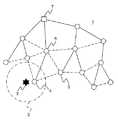
図1は、この発明の実施の形態1に係る無線ネットワークの故障診断システムにおける無線ノードのトポロジを示す説明図である。なお、この無線ネットワークは、IEEE802.15.4規格に準拠して構成されている。
図1において、無線ネットワーク1は、複数の無線ノードから構成されている。
FIG. 1 is an explanatory diagram showing the topology of a wireless node in the wireless network failure diagnosis system according to
In FIG. 1, a
無線ネットワーク1に参入する無線ノードは、無線ネットワーク1に参入済の無線ノードである親ノードにアソシエーションしてネットワークアドレスを獲得し(参入許可を受け)、獲得したネットワークアドレスを用いて他の無線ノードと通信する。
無線ネットワーク1に参入する無線ノードと、この無線ノードに参入許可を与える親ノードとの間には親子関係が生じ、ネットワークアドレスから親ノードを判断することができる。A wireless node that enters the
A parent-child relationship occurs between a wireless node that enters the
図1において、アソシエーションの関係にある無線ノードどうしは、実線で結ばれており、隣接関係にある無線ノードどうしは、破線で結ばれている。アソシエーションの関係は、無線ネットワーク1内でツリー状に形成される。アソシエーションの関係、または隣接関係にある無線ノードどうしは、直接通信することができる。
無線ネットワーク1を構成するそれぞれの無線ノードは、互いに時間的に同期がとられており、周期的にビーコンを送受信するとともに、送受信可能なアウェイク状態と送受信不可能なドーズ状態とを周期的に繰り返すパワーセーブモードで動作している。In FIG. 1, wireless nodes that are in an association relationship are connected by a solid line, and wireless nodes that are in an adjacent relationship are connected by a broken line. Association relationships are formed in a tree shape in the
Each wireless node constituting the
ここで、外乱によって外乱要因2を囲む所定エリア3内に通信異常が発生したとする。
このとき、所定エリア3内に存在する無線ノードである対象ノード4は、周辺の無線ノードと通信できなくなったことを検出して、無線チャンネルを周辺の無線ノードとの通信に使用していた通信チャンネルから、対象ノード4の正常性を確認するための正常性確認チャンネルに切り替える。Here, it is assumed that a communication abnormality has occurred in the predetermined area 3 surrounding the
At this time, the target node 4, which is a wireless node existing in the predetermined area 3, detects that communication with the surrounding wireless node is lost, and the communication using the wireless channel for communication with the surrounding wireless node The channel is switched to a normality confirmation channel for confirming the normality of the target node 4.
また、所定エリア3外に存在し、対象ノード4と通信できなくなった無線ノードである周辺ノード5は、対象ノード4の親ノードである第1親ノード6に対して通信異常を通知する。
第1親ノード6は、ドーズ状態時に無線チャンネルを通信チャンネルから正常性確認チャンネルに切り替えるとともに、対象ノード4に対する正常性確認を実行して、通信異常が外乱に起因するものであるか否かを判定する。
また、第1親ノード6は、通信異常が外乱に起因するものであった場合に、無線ネットワーク1の管理装置7に対して外乱の発生を通知する。Further, the peripheral node 5 that is outside the predetermined area 3 and is unable to communicate with the target node 4 notifies the
The
Also, the
以下、図2を参照しながら、通信チャンネルおよび正常性確認チャンネルについて詳細に説明する。
図2は、IEEE802.15.4規格に準拠して構成された無線ネットワーク1の無線チャンネルを示す説明図である。
図2において、無線ネットワーク1には、2.4GHz帯に5MHz間隔で16チャンネルの無線チャンネルが規定されている。Hereinafter, the communication channel and the normality confirmation channel will be described in detail with reference to FIG.
FIG. 2 is an explanatory diagram showing radio channels of the
In FIG. 2, the
ここで、周辺の無線ノードとの通信に使用される通信チャンネルと、対象ノード4の正常性を確認するための正常性確認チャンネルとは、周波数的に離れているほうが外乱による影響を受けにくいと考えられる。
そのため、通信チャンネルとして例えば12チャンネル(12ch)が設定されている場合には、正常性確認チャンネルとして例えば26チャンネル(26ch)が設定される。Here, the communication channel used for communication with the surrounding wireless nodes and the normality confirmation channel for confirming the normality of the target node 4 are less affected by disturbance when they are separated in frequency. Conceivable.
Therefore, for example, when 12 channels (12ch) are set as communication channels, for example, 26 channels (26ch) are set as normality confirmation channels.
続いて、図3のシーケンス図を参照しながら、上記構成の無線ネットワークの故障診断システムによる外乱発生時の処理について詳細に説明する。各無線ノードは、本処理の開始時にパワーセーブモードにおけるアウェイク状態であるとする。
まず、周辺ノード5は、対象ノード4とのリンクが切れて通信できなくなったことを検出し、通信異常の発生を検出する(ステップS11)。このとき、周辺ノード5は、対象ノード4に宛てて送信したデータが不達になること、または対象ノード4からのビーコンを受信できなくなることにより、対象ノード4と通信できなくなったことを検出する。Next, the processing at the time of occurrence of disturbance by the wireless network failure diagnosis system having the above configuration will be described in detail with reference to the sequence diagram of FIG. Assume that each wireless node is in an awake state in the power save mode at the start of this process.
First, the peripheral node 5 detects that the communication with the target node 4 is broken and communication is impossible, and detects the occurrence of a communication abnormality (step S11). At this time, the peripheral node 5 detects that the data transmitted to the target node 4 is undelivered, or that the beacon from the target node 4 cannot be received, and therefore the peripheral node 5 cannot communicate with the target node 4. .
続いて、周辺ノード5は、第1親ノード6に対して通信異常を通知する(ステップS12)。
次に、第1親ノード6は、現在の無線チャンネル(通信チャンネル)で対象ノード4に対する正常性確認を実行する(ステップS13)。このとき、この正常性確認は、外乱による通信異常によって失敗し、第1親ノード6は、通信異常の発生を確認する。
なお、対象ノード4とアソシエーションの関係にある第1親ノード6が、直接対象ノード4とのリンク切れを検出し、通信異常の発生を検出してもよい。Subsequently, the peripheral node 5 notifies the
Next, the
Note that the
続いて、第1親ノード6は、通信異常の発生を確認すると、パワーセーブモードにおけるドーズ状態時に、無線チャンネルを通信チャンネルから正常性確認チャンネルに切り替えて起動する(ステップS14)。
ここで、正常性確認チャンネルは、無線ネットワーク1を構成する各無線ノードに共通に設定されており、アソシエーション時に親ノードにより設定されてもよいし、管理装置7により直接設定されてもよい。Subsequently, when confirming the occurrence of communication abnormality, the
Here, the normality confirmation channel is set in common to each wireless node constituting the
一方、対象ノード4は、周辺の無線ノードと通信できなくなったことを検出し、パワーセーブモードにおけるドーズ状態時に、無線チャンネルを通信チャンネルから正常性確認チャンネルに切り替えて起動する(ステップS15)。このとき、対象ノード4は、周辺の無線ノードからのビーコンを受信できなくなることにより、周辺の無線ノードと通信できなくなったことを検出する。 On the other hand, the target node 4 detects that communication with the surrounding wireless node is no longer possible, and activates the wireless channel from the communication channel to the normality confirmation channel in the doze state in the power save mode (step S15). At this time, the target node 4 detects that the communication with the surrounding wireless node is disabled because the beacon cannot be received from the surrounding wireless node.
続いて、第1親ノード6は、正常性確認チャンネルで対象ノード4に対する正常性確認を実行し、通信異常が外乱に起因するものであるか否かを判定する(ステップS16)。
ここで、外乱による通信異常の影響が正常性確認チャンネルにまで及んでいなければ、この正常性確認は成功する。このとき、第1親ノード6は、対象ノード4が正常に動作していることを確認し、通信異常の発生原因が、対象ノード4の故障によるものではなく、通信チャンネルに発生した外乱による一時的なものであると判定する。
なお、第1親ノード6は、無線チャンネルを正常性確認チャンネルに切り替えても対象ノード4と通信できない場合に、無線チャンネルを別の正常性確認チャンネルに切り替えて正常性確認を再度実行してもよい。Subsequently, the
Here, if the influence of the communication abnormality due to the disturbance does not reach the normality confirmation channel, the normality confirmation is successful. At this time, the
If the
次に、第1親ノード6および対象ノード4は、ドーズ状態が終了する前に、無線チャンネルを正常性確認チャンネルから通信チャンネルに切り替える(ステップS17)。
続いて、第1親ノード6は、パワーセーブモードにおけるアウェイク状態時に、管理装置7に対して外乱の発生を通知(外乱発生通知)する(ステップS18)。Next, the
Subsequently, the
次に、第1親ノード6は、通信チャンネルで対象ノード4に対する復帰確認を周期的に実行して、通信異常から復帰したか否かを判定する(ステップS19)。
ここで、外乱要因2が収束して通信異常から復帰すると、対象ノード4は、第1親ノード6からの復帰確認に対して応答を返す(ステップS20)。
続いて、第1親ノード6は、対象ノード4からの応答を受けて、管理装置7に対して外乱の収束を通知(外乱収束通知)する(ステップS21)。このとき、管理装置7は、第1親ノード6からの外乱発生通知および外乱収束通知に基づいて、例えば外乱の継続時間を計測する。Next, the
Here, when the
Subsequently, the
次に、対象ノード4の故障によって、対象ノード4を含む所定エリア内に通信異常が発生した場合について説明する。
対象ノード4の故障によって通信異常が発生した場合には、第1親ノード6が無線チャンネルを通信チャンネルから正常性確認チャンネルに切り替えて、対象ノード4に対する正常性確認を実行しても、対象ノード4と通信できず、正常性確認は失敗する。
このとき、第1親ノード6は、通信異常の発生原因が、対象ノード4の故障によるものであると判定し、管理装置7に対して対象ノード4の故障を通知する。Next, a case where a communication abnormality occurs in a predetermined area including the target node 4 due to a failure of the target node 4 will be described.
Even if the
At this time, the
この発明の実施の形態1に係る無線ネットワークの故障診断システムによれば、無線ネットワーク1の所定エリア3内に通信異常が発生した場合、所定エリア3内に存在する対象ノード4は、周辺の無線ノードと通信できなくなったことを検出して、ドーズ状態時に無線チャンネルを通信チャンネルから正常性確認チャンネルに切り替える。
また、所定エリア3外に存在し、対象ノード4と通信できなくなった周辺ノード5は、第1親ノード6に通信異常を通知する。
また、第1親ノード6は、ドーズ状態時に無線チャンネルを通信チャンネルから正常性確認チャンネルに切り替えるとともに、対象ノード4に対する正常性確認を実行して、通信異常が外乱に起因するものであるか否かを判定する。
そのため、安価かつ簡素な構成で、第1親ノード6と通信していた他の無線ノードとの通信を継続しながら、通信異常の発生原因を判定することができる。
すなわち、外乱による通信異常の影響が正常性確認チャンネルにまで及んでいなければ、正常性確認によって対象ノード4の正常性が確認され、単一の無線チャンネルでは判定することができなかった通信異常の発生原因を判定することができる。According to the failure diagnosis system for a wireless network according to
Further, the peripheral node 5 that exists outside the predetermined area 3 and cannot communicate with the target node 4 notifies the
In addition, the
Therefore, it is possible to determine the cause of the communication abnormality while continuing communication with other wireless nodes that have been communicating with the
That is, if the influence of the communication abnormality due to the disturbance does not reach the normality confirmation channel, the normality of the target node 4 is confirmed by the normality confirmation, and the communication abnormality that cannot be determined by the single wireless channel The cause of occurrence can be determined.
さらに、対象ノード4の正常性が確認された場合、対象ノード4は、無線チャンネルを正常性確認チャンネルから通信チャンネルに切り替える。
また、第1親ノード6は、無線チャンネルを正常性確認チャンネルから通信チャンネルに切り替えるとともに、通信チャンネルで対象ノード4に対する復帰確認を周期的に実行して、通信異常から復帰したか否かを判定する。
そのため、外乱要因2が収束して通信異常から復帰したことを判定し、外乱の発生状況(外乱発生通知および外乱収束通知)を管理装置7に集約して統計的に処理(例えば、個々の外乱の継続時間の計測)することにより、外乱の発生頻度が高い無線チャンネルを検出するとともに、処理結果を無線ネットワーク1の各種設定に利用することができる。Further, when the normality of the target node 4 is confirmed, the target node 4 switches the radio channel from the normality confirmation channel to the communication channel.
Further, the
Therefore, it is determined that the
さらに、通信チャンネルと正常性確認チャンネルとが周波数的に離れているので、外乱による影響を低減して、対象ノード4に対する正常性確認の精度を向上させることができる。
すなわち、対象ノード4が故障していないにもかかわらず、対象ノード4が故障していると誤判定することを防止することができる。Furthermore, since the communication channel and the normality confirmation channel are separated in frequency, the influence of disturbance can be reduced and the accuracy of normality confirmation for the target node 4 can be improved.
That is, it is possible to prevent erroneous determination that the target node 4 has failed even though the target node 4 has not failed.
なお、上記実施の形態1の無線ネットワーク1は、IEEE802.15.4規格に準拠して構成されているとしたが、これに限定されず、無線ネットワークは、例えば無線LANの規格に準拠して構成されてもよい。
この場合も、上記実施の形態1と同様の効果を奏することができる。The
Also in this case, the same effect as in the first embodiment can be obtained.
また、上記実施の形態1では、第1親ノード6が周辺ノード5から通信異常を受けて対象ノード4に対する正常性確認を実行したが、これに限定されない。
対象ノード4と通信できなくなった周辺ノード5が、無線チャンネルを通信チャンネルから正常性確認チャンネルに切り替えて、対象ノード4に対する正常性確認を実行した場合であっても、上記実施の形態1と同様の効果を奏することができる。
ここで、対象ノード4に対する正常性確認を実行する無線ノードとして、対象ノード4の親ノードである第1親ノード6を設定した場合には、正常性確認を実行する無線ノードが限定されるので、正常性確認の効率を向上させることができる。In the first embodiment, the
Even when the peripheral node 5 that has become unable to communicate with the target node 4 switches the radio channel from the communication channel to the normality confirmation channel and executes normality confirmation for the target node 4, the same as in the first embodiment. The effect of can be produced.
Here, when the
また、上記実施の形態1では、通信チャンネルと正常性確認チャンネルとを周波数的に離して設定したが、これに限定されず、正常性確認チャンネルは、外乱の発生頻度に応じて設定されてもよい。
このとき、まず、管理装置7は、第1親ノード6からの外乱発生通知および外乱収束通知に基づいて、外乱の発生頻度が高い無線チャンネルを検出する。
続いて、管理装置7は、現在の正常性確認チャンネルが、外乱の発生頻度が高い無線チャンネルである場合に、外乱の発生頻度が低い無線チャンネルを別の正常性確認チャンネルとして選定する。例えば、16chから19chと、23chから26chとにおいて外乱の発生頻度が高いことを検出した場合、別の正常性確認チャンネルとして例えば21chを選定する。
次に、管理装置7は、選定された別の正常性確認チャンネルを無線ネットワーク1の各無線ノードに設定する。
この場合、対象ノード4に対する正常性確認の精度をさらに向上させることができ、対象ノード4が故障していないにもかかわらず、対象ノード4が故障していると誤判定することをさらに防止することができる。In the first embodiment, the communication channel and the normality confirmation channel are set apart from each other in terms of frequency. However, the present invention is not limited to this, and the normality confirmation channel may be set according to the frequency of occurrence of disturbance. Good.
At this time, first, the
Subsequently, when the current normality confirmation channel is a radio channel with high disturbance occurrence frequency, the
Next, the
In this case, the accuracy of normality confirmation for the target node 4 can be further improved, and it is further prevented from erroneously determining that the target node 4 has failed even though the target node 4 has not failed. be able to.
また、通信異常が発生していない場合であっても、正常性確認チャンネルにおける外乱の発生頻度を検出して、正常性確認チャンネルを外乱の発生頻度の低い無線チャンネルに設定してもよい。
このとき、まず、無線ネットワーク1を構成する複数の無線ノードのうち少なくとも2つの無線ノードは、パワーセーブモードにおけるドーズ状態時に、無線チャンネルを通信チャンネルから正常性確認チャンネルに切り替える。
続いて、無線チャンネルを切り替えたこれらの無線ノードは、正常性確認チャンネルの通信状態を確認して、管理装置7に通信状態を通知する。
次に、管理装置7は、通知された通信状態に基づいて、外乱の発生頻度が高い無線チャンネルを検出する。
続いて、管理装置7は、現在の正常性確認チャンネルが、外乱の発生頻度が高い無線チャンネルである場合に、外乱の発生頻度が低い無線チャンネルを別の正常性確認チャンネルとして選定し、選定された別の正常性確認チャンネルを無線ネットワーク1の各無線ノードに設定する。
この場合も、対象ノード4に対する正常性確認の精度をさらに向上させることができ、対象ノード4が故障していないにもかかわらず、対象ノード4が故障していると誤判定することをさらに防止することができる。Further, even when no communication abnormality has occurred, the occurrence frequency of disturbance in the normality confirmation channel may be detected, and the normality confirmation channel may be set to a radio channel with a low occurrence frequency of disturbance.
At this time, first, at least two of the plurality of wireless nodes constituting the
Subsequently, these wireless nodes that have switched the wireless channel confirm the communication state of the normality confirmation channel and notify the
Next, the
Subsequently, when the current normality confirmation channel is a radio channel with a high disturbance occurrence frequency, the
Also in this case, the accuracy of the normality confirmation for the target node 4 can be further improved, and it is further prevented that the target node 4 is erroneously determined to be faulty even though the target node 4 is not faulty. can do.
実施の形態2.
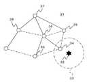
図4は、この発明の実施の形態2に係る無線ネットワークの故障診断システムにおける無線ノードのトポロジを示す説明図である。
図4において、無線ネットワーク31は、複数の無線ノードから構成されている。
また、無線ネットワーク31を構成するそれぞれの無線ノードは、常に送受信可能なアクティブモードで動作している。
FIG. 4 is an explanatory diagram showing the topology of the wireless node in the wireless network failure diagnosis system according to
In FIG. 4, the
Each wireless node constituting the
ここで、外乱によって外乱要因32を囲む所定エリア33内に通信異常が発生したとする。
このとき、所定エリア33内に存在する無線ノードである対象ノード34は、周辺の無線ノードと通信できなくなったことを検出して、無線チャンネルを周辺の無線ノードとの通信に使用していた通信チャンネルから、対象ノード34の正常性を確認するための正常性確認チャンネルに切り替える。Here, it is assumed that a communication abnormality occurs in the predetermined
At this time, the
また、所定エリア33外に存在し、対象ノード34と通信できなくなった無線ノードである周辺ノード35は、対象ノード34の親ノードである第1親ノード36に対して通信異常を通知する。
第1親ノード36は、自身の親ノードである第2親ノード37に対して無線チャンネルの切り替えを通知して、無線チャンネルを通信チャンネルから正常性確認チャンネルに切り替える。Further, the
The
また、第1親ノード36は、対象ノード34に対する正常性確認を実行して、通信異常が外乱に起因するものであるか否かを判定する。
第2親ノード37は、例えば無線ノード38から第1親ノード36を経由する通信が発生した際に、送信元の無線ノード38に対して、第1親ノード36が無線チャンネルを切り替えている旨を通知する。
その他の構成については、前述の実施の形態1と同様であり、その説明は省略する。Further, the
The
Other configurations are the same as those in the first embodiment, and the description thereof is omitted.
以下、図5のシーケンス図を参照しながら、上記構成の無線ネットワークの故障診断システムによる外乱発生時の処理について詳細に説明する。
まず、周辺ノード35は、対象ノード34とのリンクが切れて通信できなくなったことを検出し、通信異常の発生を検出する(ステップS41)。このとき、周辺ノード35は、対象ノード34に宛てて送信したデータが不達になること、または対象ノード34からのビーコンを受信できなくなることにより、対象ノード34と通信できなくなったことを検出する。In the following, a detailed description will be given of processing when a disturbance occurs by the wireless network failure diagnosis system configured as described above, with reference to the sequence diagram of FIG.
First, the
続いて、周辺ノード35は、第1親ノード36に対して通信異常を通知する(ステップS42)。
次に、第1親ノード36は、現在の無線チャンネル(通信チャンネル)で対象ノード34に対する正常性確認を実行する(ステップS43)。このとき、この正常性確認は、外乱による通信異常によって失敗し、第1親ノード36は、通信異常の発生を確認する。
なお、対象ノード34とアソシエーションの関係にある第1親ノード36が、直接対象ノード34とのリンク切れを検出し、通信異常の発生を検出してもよい。Subsequently, the
Next, the
Note that the
続いて、第1親ノード36は、通信異常の発生を確認すると、第2親ノード37に対して無線チャンネルの切り替えを通知(チャンネル切り替え通知)して(ステップS44)、無線チャンネルを通信チャンネルから正常性確認チャンネルに切り替える(ステップS45)。
ここで、正常性確認チャンネルは、無線ネットワーク31を構成する各無線ノードに共通に設定されている。Subsequently, when the occurrence of communication abnormality is confirmed, the
Here, the normality confirmation channel is set in common to each wireless node constituting the
一方、対象ノード34は、周辺の無線ノードと通信できなくなったことを検出し、通信できない状態が所定時間経過した場合に、無線チャンネルを通信チャンネルから正常性確認チャンネルに切り替える(ステップS46)。このとき、対象ノード34は、周辺の無線ノードからのビーコンを受信できなくなることにより、周辺の無線ノードと通信できなくなったことを検出する。 On the other hand, the
続いて、第1親ノード36は、正常性確認チャンネルで対象ノード34に対する正常性確認を実行し、通信異常が外乱に起因するものであるか否かを判定する(ステップS47)。
ここで、外乱による通信異常の影響が正常性確認チャンネルにまで及んでいなければ、この正常性確認は成功する。このとき、第1親ノード36は、対象ノード34が正常に動作していることを確認し、通信異常の発生原因が、対象ノード34の故障によるものではなく、通信チャンネルに発生した外乱による一時的なものであると判定する。
なお、第1親ノード36は、無線チャンネルを正常性確認チャンネルに切り替えても対象ノード34と通信できない場合に、無線チャンネルを別の正常性確認チャンネルに切り替えて正常性確認を再度実行してもよい。Subsequently, the
Here, if the influence of the communication abnormality due to the disturbance does not reach the normality confirmation channel, the normality confirmation is successful. At this time, the
If the
次に、第1親ノード36および対象ノード34は、無線チャンネルを正常性確認チャンネルから通信チャンネルに切り替える(ステップS48)。
続いて、第1親ノード36は、第2親ノード37に対して無線チャンネルの復帰を通知(チャンネル復帰通知)する(ステップS49)。Next, the
Subsequently, the
ここで、第1親ノード36が無線チャンネルを切り替えて正常性確認を実行している間に、無線ノード38から第1親ノード36を経由する通信が発生した場合について説明する。
まず、無線ノード38は、例えば無線ノード39に宛てて、第1親ノード36を経由するデータを送信する(ステップS50)。このとき、第1親ノード36が無線チャンネルを切り替えているので、このデータ送信は失敗し、無線ノード38は、第1親ノード36と通信できないことを確認する。Here, a case will be described in which communication from the
First, the
続いて、無線ノード38は、通信経路をアドホックルーティングからツリールーティングに切り替えて、第2親ノード37にデータを送信する(ステップS51)。
第2親ノード37は、第1親ノード36が無線チャンネルを切り替えていることを把握しているので、無線ノード38からのデータ送信に対して、第1親ノード36への通信経路が無効になっていることを示すルートエラーメッセージ(RERR)を返信する(ステップS52)。Subsequently, the
Since the
次に、無線ノード38は、無線ノード39までの通信経路を再構築してデータを送信する(ステップS53)。
ここで、第1親ノード36の周辺の無線ノードが、第1親ノード36と通信できなくなったことを検出し、第2親ノード37に対して通信異常を通知した場合であっても、第2親ノード37は、第1親ノード36が無線チャンネルを切り替えていることを把握しているので、第1親ノード36に対する正常性確認を実行しない。
その他の動作については、前述の実施の形態1と同様であり、その説明は省略する。Next, the
Here, even when a wireless node around the
Other operations are the same as those in the first embodiment, and a description thereof will be omitted.
この発明の実施の形態2に係る無線ネットワークの故障診断システムによれば、無線ネットワーク31の所定エリア33内に通信異常が発生した場合、所定エリア33内に存在する対象ノード34は、周辺の無線ノードと通信できなくなったことを検出して、無線チャンネルを通信チャンネルから正常性確認チャンネルに切り替える。
また、所定エリア33外に存在し、対象ノード34と通信できなくなった周辺ノード35は、第1親ノード36に通信異常を通知する。
また、第1親ノード36は、第2親ノード37に対して無線チャンネルの切り替えを通知して、無線チャンネルを通信チャンネルから正常性確認チャンネルに切り替えるとともに、対象ノード34に対する正常性確認を実行して、通信異常が外乱に起因するものであるか否かを判定する。
また、第2親ノード37は、第1親ノード36を経由する通信が発生した際に、送信元の無線ノード38に対してRERRを返信するとともに、第1親ノード36の周辺の無線ノードから通信異常が通知された場合であっても、第1親ノード36に対する正常性確認を実行しない。
そのため、安価かつ簡素な構成で、要求される通信を継続しながら、通信異常の発生原因を判定することができる。
すなわち、外乱による通信異常の影響が正常性確認チャンネルにまで及んでいなければ、正常性確認によって対象ノード34の正常性が確認され、単一の無線チャンネルでは判定することができなかった通信異常の発生原因を判定することができる。According to the failure diagnosis system for a wireless network according to
Further, the
Further, the
Further, when communication via the
Therefore, it is possible to determine the cause of the communication abnormality while continuing the required communication with an inexpensive and simple configuration.
That is, if the influence of the communication abnormality due to the disturbance does not reach the normality confirmation channel, the normality of the
なお、上記実施の形態2の対象ノード34は、第1親ノード36による正常性確認によって、正常に動作していることが確認された際に、無線チャンネルを正常性確認チャンネルから通信チャンネルに切り替えたが、これに限定されない。
対象ノード34は、無線チャンネルを通信チャンネルから正常性確認チャンネルに切り替えた後、所定時間を経過しても第1親ノード36による正常性確認が実行されない場合に、無線チャンネルを正常性確認チャンネルから通信チャンネルに切り替えて、周辺の無線ノードとの通信を試みてもよい。
これにより、外乱による通信異常の影響が第1親ノード36にまで及んでいた場合に、通信異常からの復帰が遅延することを防止することができる。The
The
Thereby, when the influence of the communication abnormality due to the disturbance reaches the
1、31 無線ネットワーク、3、33 所定エリア、5、35 周辺ノード、6、36親ノード、7 管理装置、37、第2親ノード。 1, 31 Wireless network, 3, 33 Predetermined area, 5, 35 Peripheral node, 6, 36 parent node, 7 Management device, 37, Second parent node.
Claims (16)
Translated fromJapanese前記複数の無線ノードは、送受信可能なアウェイク状態と送受信不可能なドーズ状態とを互いに同期して繰り返し、
所定エリア内に通信異常が発生した場合、
前記所定エリア内に存在する無線ノードである対象ノードは、周辺の無線ノードと通信できなくなったことを検出して、無線チャンネルを前記周辺の無線ノードとの通信に使用していた通信チャンネルから、前記対象ノードの正常性を確認するための正常性確認チャンネルに切り替え、
前記所定エリア外に存在し、前記対象ノードと通信できなくなった無線ノードは、前記ドーズ状態時に無線チャンネルを前記通信チャンネルから前記正常性確認チャンネルに切り替えるとともに、前記対象ノードに対する正常性確認を実行して、前記通信異常が外乱に起因するものであるか否かを判定することを特徴とする無線ネットワークの故障診断システム。A wireless network failure diagnosis system comprising a plurality of wireless nodes constituting a wireless network,
The plurality of wireless nodes repeat an awake state in which transmission / reception is possible and a doze state in which transmission / reception is not possible in synchronization with each other,
If a communication error occurs in the specified area,
The target node, which is a wireless node existing in the predetermined area, detects that communication with the surrounding wireless node is lost, and from the communication channel used for communication with the surrounding wireless node, Switch to the normality confirmation channel for confirming the normality of the target node,
The wireless node that is outside the predetermined area and cannot communicate with the target node switches the radio channel from the communication channel to the normality confirmation channel in the doze state, and executes normality confirmation for the target node. And determining whether the communication abnormality is caused by disturbance or not.
前記複数の無線ノードは、送受信可能なアウェイク状態と送受信不可能なドーズ状態とを互いに同期して繰り返し、
所定エリア内に通信異常が発生した場合、
前記所定エリア内に存在する無線ノードである対象ノードは、周辺の無線ノードと通信できなくなったことを検出して、無線チャンネルを前記周辺の無線ノードとの通信に使用していた通信チャンネルから、前記対象ノードの正常性を確認するための正常性確認チャンネルに切り替え、
前記所定エリア外に存在し、前記対象ノードと通信できなくなった無線ノードは、前記対象ノードの親ノードである第1親ノードに対して前記通信異常を通知し、
前記第1親ノードは、前記ドーズ状態時に無線チャンネルを前記通信チャンネルから前記正常性確認チャンネルに切り替えるとともに、前記対象ノードに対する正常性確認を実行して、前記通信異常が外乱に起因するものであるか否かを判定することを特徴とする無線ネットワークの故障診断システム。A wireless network failure diagnosis system comprising a plurality of wireless nodes, wherein a wireless node entering a wireless network receives entry permission from a parent node that has already entered the wireless network and forms a network in a tree shape. There,
The plurality of wireless nodes repeat an awake state in which transmission / reception is possible and a doze state in which transmission / reception is not possible in synchronization with each other,
If a communication error occurs in the specified area,
The target node, which is a wireless node existing in the predetermined area, detects that communication with the surrounding wireless node is lost, and from the communication channel used for communication with the surrounding wireless node, Switch to the normality confirmation channel for confirming the normality of the target node,
A wireless node that exists outside the predetermined area and cannot communicate with the target node notifies the communication abnormality to the first parent node that is a parent node of the target node,
The first parent node switches the radio channel from the communication channel to the normality confirmation channel in the doze state, and executes normality confirmation for the target node, and the communication abnormality is caused by disturbance. A fault diagnosis system for a wireless network, characterized by determining whether or not.
所定エリア内に通信異常が発生した場合、
前記所定エリア内に存在する無線ノードである対象ノードは、周辺の無線ノードと通信できなくなったことを検出して、無線チャンネルを前記周辺の無線ノードとの通信に使用していた通信チャンネルから、前記対象ノードの正常性を確認するための正常性確認チャンネルに切り替え、
前記所定エリア外に存在し、前記対象ノードと通信できなくなった無線ノードは、前記対象ノードの親ノードである第1親ノードに対して前記通信異常を通知し、
前記第1親ノードは、自身の親ノードである第2親ノードに対して無線チャンネルの切り替えを通知して、無線チャンネルを前記通信チャンネルから前記正常性確認チャンネルに切り替えるとともに、前記対象ノードに対する正常性確認を実行して、前記通信異常が外乱に起因するものであるか否かを判定し、
前記第2親ノードは、前記第1親ノードを経由する通信が発生した際に、送信元の無線ノードに対して、前記第1親ノードが無線チャンネルを切り替えている旨を通知することを特徴とする無線ネットワークの故障診断システム。A wireless network failure diagnosis system comprising a plurality of wireless nodes, wherein a wireless node entering a wireless network receives entry permission from a parent node that has already entered the wireless network and forms a network in a tree shape. There,
If a communication error occurs in the specified area,
The target node, which is a wireless node existing in the predetermined area, detects that communication with the surrounding wireless node is lost, and from the communication channel used for communication with the surrounding wireless node, Switch to the normality confirmation channel for confirming the normality of the target node,
A wireless node that exists outside the predetermined area and cannot communicate with the target node notifies the communication abnormality to the first parent node that is a parent node of the target node,
The first parent node notifies the second parent node, which is its own parent node, of switching of the radio channel, switches the radio channel from the communication channel to the normality confirmation channel, and is normal to the target node. To determine whether or not the communication abnormality is due to disturbance,
When the communication via the first parent node occurs, the second parent node notifies the transmission source wireless node that the first parent node is switching the wireless channel. Wireless network fault diagnosis system.
前記管理装置は、前記外乱の発生頻度が低い無線チャンネルを別の正常性確認チャンネルとして選定し、前記別の正常性確認チャンネルを前記複数の無線ノードのそれぞれに設定することを特徴とする請求項1から請求項3までの何れか1項に記載の無線ネットワークの故障診断システム。The wireless node that executes normality confirmation for the target node notifies the occurrence of the disturbance to the wireless network management device,
The management apparatus selects a radio channel with a low occurrence frequency of the disturbance as another normality confirmation channel, and sets the other normality confirmation channel in each of the plurality of radio nodes. The failure diagnosis system for a wireless network according to any one of claims 1 to 3.
前記管理装置は、前記通信状態に基づいて前記外乱の発生頻度が低い無線チャンネルを別の正常性確認チャンネルとして選定し、前記別の正常性確認チャンネルを前記複数の無線ノードのそれぞれに設定することを特徴とする請求項1または請求項2に記載の無線ネットワークの故障診断システム。At least two wireless nodes of the plurality of wireless nodes switch the wireless channel from the communication channel to the normality confirmation channel in the doze state, and confirm the communication state of the normality confirmation channel to check the communication state of the wireless network. Notify the management device,
The management device selects a radio channel with low disturbance occurrence frequency as another normality confirmation channel based on the communication state, and sets the other normality confirmation channel in each of the plurality of radio nodes. The failure diagnosis system for a wireless network according to claim 1 or 2, characterized in that:
前記対象ノードは、無線チャンネルを前記正常性確認チャンネルから前記通信チャンネルに切り替え、
前記対象ノードに対する正常性確認を実行した無線ノードは、無線チャンネルを前記正常性確認チャンネルから前記通信チャンネルに切り替えるとともに、前記対象ノードに対する復帰確認を周期的に実行して、前記通信異常から復帰したか否かを判定することを特徴とする請求項1から請求項6までの何れか1項に記載の無線ネットワークの故障診断システム。When the normality of the target node is confirmed by communication in the normality confirmation channel,
The target node switches the radio channel from the normality confirmation channel to the communication channel,
The wireless node that executed the normality check for the target node switches from the normality check channel to the communication channel, and periodically performs return check for the target node to recover from the communication abnormality. 7. The wireless network failure diagnosis system according to claim 1, wherein the wireless network failure diagnosis system according to claim 1 is determined.
所定エリア内に通信異常が発生した場合に、
前記所定エリア内に存在し、周辺の無線ノードと通信できなくなったことを検出した無線ノードである対象ノードの無線チャンネルを、前記周辺の無線ノードとの通信に使用していた通信チャンネルから、前記対象ノードの正常性を確認するための正常性確認チャンネルに切り替えるステップと、
前記所定エリア外に存在し、前記対象ノードと通信できなくなった無線ノードの無線チャンネルを、前記ドーズ状態時に前記通信チャンネルから前記正常性確認チャンネルに切り替えるステップと、
前記対象ノードと通信できなくなった無線ノードにより、前記対象ノードに対する正常性確認を実行して、前記通信異常が外乱に起因するものであるか否かを判定するステップと、を含むことを特徴とする無線ネットワークの故障診断方法。A wireless network failure diagnosis method comprising a plurality of wireless nodes that constitutes a wireless network and repeats an awake state in which transmission / reception is possible and a doze state in which transmission / reception is impossible, in synchronization with each other,
When a communication error occurs in the specified area,
A wireless channel of a target node that is a wireless node that is present in the predetermined area and has detected that communication with a surrounding wireless node is no longer possible, from a communication channel that is used for communication with the surrounding wireless node, Switching to a health check channel to check the health of the target node;
Switching a radio channel of a radio node that exists outside the predetermined area and cannot communicate with the target node from the communication channel to the normality confirmation channel in the doze state;
Performing a normality check on the target node by a wireless node that has become unable to communicate with the target node, and determining whether the communication abnormality is caused by a disturbance. A failure diagnosis method for a wireless network.
所定エリア内に通信異常が発生した場合に、
前記所定エリア内に存在し、周辺の無線ノードと通信できなくなったことを検出した無線ノードである対象ノードの無線チャンネルを、前記周辺の無線ノードとの通信に使用していた通信チャンネルから、前記対象ノードの正常性を確認するための正常性確認チャンネルに切り替えるステップと、
前記所定エリア外に存在し、前記対象ノードと通信できなくなった無線ノードから、前記対象ノードの親ノードである第1親ノードに対して前記通信異常を通知するステップと、
前記第1親ノードの無線チャンネルを、前記ドーズ状態時に前記通信チャンネルから前記正常性確認チャンネルに切り替えるステップと、
前記第1親ノードにより、前記対象ノードに対する正常性確認を実行して、前記通信異常が外乱に起因するものであるか否かを判定するステップと、を含むことを特徴とする無線ネットワークの故障診断方法。A wireless node that participates in a wireless network is entered from a parent node that is a wireless node that has already entered the wireless network. A wireless network failure diagnosis method that forms a tree-like network with permission,
When a communication error occurs in the specified area,
A wireless channel of a target node that is a wireless node that is present in the predetermined area and has detected that communication with a surrounding wireless node is no longer possible, from a communication channel that is used for communication with the surrounding wireless node, Switching to a health check channel to check the health of the target node;
Notifying the communication abnormality from a wireless node that exists outside the predetermined area and is unable to communicate with the target node to a first parent node that is a parent node of the target node;
Switching the radio channel of the first parent node from the communication channel to the normality confirmation channel in the doze state;
Performing a normality check on the target node by the first parent node to determine whether the communication abnormality is caused by disturbance or not. Diagnostic method.
所定エリア内に通信異常が発生した場合に、
前記所定エリア内に存在し、周辺の無線ノードと通信できなくなったことを検出した無線ノードである対象ノードの無線チャンネルを、前記周辺の無線ノードとの通信に使用していた通信チャンネルから、前記対象ノードの正常性を確認するための正常性確認チャンネルに切り替えるステップと、
前記所定エリア外に存在し、前記対象ノードと通信できなくなった無線ノードから、前記対象ノードの親ノードである第1親ノードに対して前記通信異常を通知するステップと、
前記第1親ノードから、前記第1親ノードの親ノードである第2親ノードに対して無線チャンネルの切り替えを通知するステップと、
前記第1親ノードの無線チャンネルを、前記通信チャンネルから前記正常性確認チャンネルに切り替えるステップと、
前記第1親ノードにより、前記対象ノードに対する正常性確認を実行して、前記通信異常が外乱に起因するものであるか否かを判定するステップと、
前記第1親ノードを経由する通信が発生した際に、前記第2親ノードから、送信元の無線ノードに対して、前記第1親ノードが無線チャンネルを切り替えている旨を通知するステップと、を含むことを特徴とする無線ネットワークの故障診断方法。A wireless network failure diagnosis method comprising a plurality of wireless nodes, wherein a wireless node entering a wireless network receives entry permission from a parent node that has already entered the wireless network and forms a network in a tree shape. There,
When a communication error occurs in the specified area,
A wireless channel of a target node that is a wireless node that is present in the predetermined area and has detected that communication with a surrounding wireless node is no longer possible, from a communication channel that is used for communication with the surrounding wireless node, Switching to a health check channel to check the health of the target node;
Notifying the communication abnormality from a wireless node that exists outside the predetermined area and is unable to communicate with the target node to a first parent node that is a parent node of the target node;
Notifying the second parent node, which is the parent node of the first parent node, of the switching of the radio channel from the first parent node;
Switching the radio channel of the first parent node from the communication channel to the normality confirmation channel;
Performing a normality check on the target node by the first parent node to determine whether the communication abnormality is due to disturbance;
Notifying that the first parent node is switching the radio channel from the second parent node to the source radio node when communication via the first parent node occurs; A fault diagnosis method for a wireless network, comprising:
前記管理装置により、前記外乱の発生頻度が低い無線チャンネルを、別の正常性確認チャンネルとして選定するステップと、
前記管理装置により、前記別の正常性確認チャンネルを前記複数の無線ノードのそれぞれに設定するステップと、を含むことを特徴とする請求項9から請求項11までの何れか1項に記載の無線ネットワークの故障診断方法。Notifying the occurrence of the disturbance from a wireless node that performs normality confirmation for the target node to a management device of the wireless network;
Selecting, by the management device, a radio channel with a low frequency of disturbance as another normality confirmation channel;
The wireless communication according to any one of claims 9 to 11, further comprising: setting the separate normality confirmation channel to each of the plurality of wireless nodes by the management device. Network fault diagnosis method.
無線チャンネルが切り替えられた前記少なくとも2つの無線ノードにより、前記正常性確認チャンネルの通信状態を確認して前記無線ネットワークの管理装置に通知するステップと、
前記管理装置により、前記通信状態に基づいて前記外乱の発生頻度が低い無線チャンネルを、別の正常性確認チャンネルとして選定するステップと、
前記管理装置により、前記別の正常性確認チャンネルを前記複数の無線ノードのそれぞれに設定するステップと、を含むことを特徴とする請求項9または請求項10に記載の無線ネットワークの故障診断方法。Switching radio channels of at least two radio nodes among the plurality of radio nodes from the communication channel to the normality confirmation channel in the doze state;
Confirming the communication status of the normality confirmation channel by the at least two radio nodes whose radio channels are switched, and notifying the management device of the radio network;
Selecting, by the management device, a radio channel having a low frequency of occurrence of the disturbance based on the communication state as another normality confirmation channel;
The wireless network failure diagnosis method according to claim 9, further comprising: setting the separate normality confirmation channel in each of the plurality of wireless nodes by the management device.
前記対象ノードの無線チャンネルを前記正常性確認チャンネルから前記通信チャンネルに切り替えるステップと、
前記対象ノードに対する正常性確認を実行した無線ノードの無線チャンネルを前記正常性確認チャンネルから前記通信チャンネルに切り替えるステップと、
前記対象ノードに対する正常性確認を実行した無線ノードにより、前記対象ノードに対する復帰確認を周期的に実行して、前記通信異常から復帰したか否かを判定するステップと、を含むことを特徴とする請求項9から請求項14までの何れか1項に記載の無線ネットワークの故障診断方法。When the normality of the target node is confirmed by communication in the normality confirmation channel,
Switching the wireless channel of the target node from the normality confirmation channel to the communication channel;
Switching the radio channel of the radio node that has executed the normality check for the target node from the normality check channel to the communication channel;
Including a step of periodically executing return confirmation for the target node by the wireless node that has executed normality confirmation for the target node to determine whether or not the communication node has recovered from the communication abnormality. The wireless network failure diagnosis method according to any one of claims 9 to 14.
前記対象ノードの無線チャンネルを前記正常性確認チャンネルから前記通信チャンネルに切り替えるステップと、
前記対象ノードにより、前記周辺の無線ノードとの通信を試みるステップと、を含むことを特徴とする請求項9から請求項15までの何れか1項に記載の無線ネットワークの故障診断方法。After switching the wireless channel of the target node from the communication channel to the normality confirmation channel, when there is no request from the wireless node that performs normality confirmation for the target node,
Switching the wireless channel of the target node from the normality confirmation channel to the communication channel;
The wireless network failure diagnosis method according to any one of claims 9 to 15, further comprising a step of attempting communication with the surrounding wireless node by the target node.
Priority Applications (1)
| Application Number | Priority Date | Filing Date | Title |
|---|---|---|---|
| JP2007065109AJP2008228046A (en) | 2007-03-14 | 2007-03-14 | Failure diagnosis system and failure diagnosis method for wireless network |
Applications Claiming Priority (1)
| Application Number | Priority Date | Filing Date | Title |
|---|---|---|---|
| JP2007065109AJP2008228046A (en) | 2007-03-14 | 2007-03-14 | Failure diagnosis system and failure diagnosis method for wireless network |
Publications (1)
| Publication Number | Publication Date |
|---|---|
| JP2008228046Atrue JP2008228046A (en) | 2008-09-25 |
Family
ID=39846100
Family Applications (1)
| Application Number | Title | Priority Date | Filing Date |
|---|---|---|---|
| JP2007065109APendingJP2008228046A (en) | 2007-03-14 | 2007-03-14 | Failure diagnosis system and failure diagnosis method for wireless network |
Country Status (1)
| Country | Link |
|---|---|
| JP (1) | JP2008228046A (en) |
Cited By (3)
| Publication number | Priority date | Publication date | Assignee | Title |
|---|---|---|---|---|
| KR20100093389A (en)* | 2009-02-16 | 2010-08-25 | 삼성전자주식회사 | Apparatus and method for managementing path between nodes in mobile communication system |
| JP2012147090A (en)* | 2011-01-07 | 2012-08-02 | Hitachi Ltd | Radio communication system, base station and server |
| CN107371175A (en)* | 2017-08-17 | 2017-11-21 | 东南大学 | A Fault Detection Method for Self-Organizing Networks Using Collaborative Prediction |
Citations (8)
| Publication number | Priority date | Publication date | Assignee | Title |
|---|---|---|---|---|
| JPS6489827A (en)* | 1987-09-30 | 1989-04-05 | Toshiba Corp | Talking channel switching system in portable telephone system |
| JPH07298345A (en)* | 1994-04-25 | 1995-11-10 | Oki Electric Ind Co Ltd | Base station testing method for mobile communication system and base station |
| JPH10190566A (en)* | 1996-12-20 | 1998-07-21 | Nec Corp | System for controlling transmission error |
| JP2002290306A (en)* | 2001-03-28 | 2002-10-04 | Mitsubishi Electric Corp | Automatic meter reading system |
| JP2005080316A (en)* | 2003-09-03 | 2005-03-24 | Samsung Electronics Co Ltd | Routing route restoration method in tree structure wireless network |
| JP2005303379A (en)* | 2004-04-06 | 2005-10-27 | Oki Electric Ind Co Ltd | Method and device of radio communication |
| JP2006086856A (en)* | 2004-09-16 | 2006-03-30 | Oki Electric Ind Co Ltd | Radio communication control method and radio communication equipment |
| JP2006262386A (en)* | 2005-03-18 | 2006-09-28 | Toshiba Corp | Control system |
- 2007
- 2007-03-14JPJP2007065109Apatent/JP2008228046A/enactivePending
Patent Citations (8)
| Publication number | Priority date | Publication date | Assignee | Title |
|---|---|---|---|---|
| JPS6489827A (en)* | 1987-09-30 | 1989-04-05 | Toshiba Corp | Talking channel switching system in portable telephone system |
| JPH07298345A (en)* | 1994-04-25 | 1995-11-10 | Oki Electric Ind Co Ltd | Base station testing method for mobile communication system and base station |
| JPH10190566A (en)* | 1996-12-20 | 1998-07-21 | Nec Corp | System for controlling transmission error |
| JP2002290306A (en)* | 2001-03-28 | 2002-10-04 | Mitsubishi Electric Corp | Automatic meter reading system |
| JP2005080316A (en)* | 2003-09-03 | 2005-03-24 | Samsung Electronics Co Ltd | Routing route restoration method in tree structure wireless network |
| JP2005303379A (en)* | 2004-04-06 | 2005-10-27 | Oki Electric Ind Co Ltd | Method and device of radio communication |
| JP2006086856A (en)* | 2004-09-16 | 2006-03-30 | Oki Electric Ind Co Ltd | Radio communication control method and radio communication equipment |
| JP2006262386A (en)* | 2005-03-18 | 2006-09-28 | Toshiba Corp | Control system |
Cited By (5)
| Publication number | Priority date | Publication date | Assignee | Title |
|---|---|---|---|---|
| KR20100093389A (en)* | 2009-02-16 | 2010-08-25 | 삼성전자주식회사 | Apparatus and method for managementing path between nodes in mobile communication system |
| KR101641096B1 (en)* | 2009-02-16 | 2016-07-20 | 삼성전자주식회사 | Apparatus and method for managementing path between nodes in mobile communication system |
| JP2012147090A (en)* | 2011-01-07 | 2012-08-02 | Hitachi Ltd | Radio communication system, base station and server |
| CN107371175A (en)* | 2017-08-17 | 2017-11-21 | 东南大学 | A Fault Detection Method for Self-Organizing Networks Using Collaborative Prediction |
| CN107371175B (en)* | 2017-08-17 | 2020-02-18 | 东南大学 | A Self-Organizing Network Fault Detection Method Using Collaborative Prediction |
Similar Documents
| Publication | Publication Date | Title |
|---|---|---|
| EP1886452B1 (en) | Method and system for redundantly connected wireless sensors | |
| US7848223B2 (en) | Redundantly connected wireless sensor networking methods | |
| CN101395868B (en) | Reporting interference-free channels and helping orphaned nodes in wireless networks | |
| EP2579508B1 (en) | Multiple-fault-tolerant ethernet network for industrial control | |
| JP5297220B2 (en) | Automatic meter reading radio system and radio communication terminal device used therefor | |
| US10588173B2 (en) | Wi-Fi mesh fire detection system | |
| JP2007180830A (en) | Redundant supervisory control system and redundant switching method for the same system | |
| JP2012080356A (en) | Radio terminal, program for determining terminal to accommodate the same, radio network and network configuring device | |
| CN102780615B (en) | Link backup method and routing forwarding device | |
| JP2008187603A (en) | Wireless communication network system, wireless communication method, network construction method, communication path switching method, center station, relay station, and terminal station | |
| CN110838962A (en) | Marine network system and marine system | |
| US9197441B2 (en) | Method and system for service protection | |
| JP4362717B2 (en) | Multihop data transfer path redundancy / switching method, network system | |
| CN101022391A (en) | RPR bidge redundancy protecting method and RPR bridge ring equipment | |
| US9398614B2 (en) | Data collection system, data collection device, wireless communication device, and communication method for collecting data | |
| JP2008228046A (en) | Failure diagnosis system and failure diagnosis method for wireless network | |
| CN101686199B (en) | Method, device and system for processing control message in Ethernet protection system | |
| JP4287734B2 (en) | Network equipment | |
| US20100329278A1 (en) | Apparatus for selecting operating time slot in mesh network | |
| Elhadef et al. | Self-diagnosing wireless mesh and ad-hoc networks using an adaptable comparison-based approach | |
| JP2009224978A (en) | Radio communication apparatus, radio communication system, and network restructuring method of radio communication apparatus | |
| JP2002199473A (en) | Data collection system and data collection method | |
| EP2750336B1 (en) | Inter-loop service protection method and apparatus | |
| JP2004040591A (en) | Wireless LAN system and communication method thereof | |
| JP2021044805A (en) | Two-hop wireless network communication |
Legal Events
| Date | Code | Title | Description |
|---|---|---|---|
| A621 | Written request for application examination | Free format text:JAPANESE INTERMEDIATE CODE: A621 Effective date:20091127 | |
| A977 | Report on retrieval | Free format text:JAPANESE INTERMEDIATE CODE: A971007 Effective date:20111110 | |
| A131 | Notification of reasons for refusal | Free format text:JAPANESE INTERMEDIATE CODE: A131 Effective date:20111122 | |
| A02 | Decision of refusal | Free format text:JAPANESE INTERMEDIATE CODE: A02 Effective date:20120313 |