JP2008227261A - Substrate processing equipment - Google Patents
Substrate processing equipmentDownload PDFInfo
- Publication number
- JP2008227261A JP2008227261AJP2007065059AJP2007065059AJP2008227261AJP 2008227261 AJP2008227261 AJP 2008227261AJP 2007065059 AJP2007065059 AJP 2007065059AJP 2007065059 AJP2007065059 AJP 2007065059AJP 2008227261 AJP2008227261 AJP 2008227261A
- Authority
- JP
- Japan
- Prior art keywords
- gas supply
- valve
- supply pipe
- carrier gas
- wafer
- Prior art date
- Legal status (The legal status is an assumption and is not a legal conclusion. Google has not performed a legal analysis and makes no representation as to the accuracy of the status listed.)
- Pending
Links
- 239000000758substrateSubstances0.000titleclaimsabstractdescription21
- 239000007789gasSubstances0.000claimsabstractdescription112
- 239000012159carrier gasSubstances0.000claimsabstractdescription75
- 239000007788liquidSubstances0.000claimsabstractdescription34
- 230000008016vaporizationEffects0.000claimsabstractdescription19
- 238000009834vaporizationMethods0.000claimsabstractdescription17
- 239000002994raw materialSubstances0.000claimsabstractdescription8
- 238000010438heat treatmentMethods0.000claimsdescription5
- 235000012431wafersNutrition0.000description57
- 239000010408filmSubstances0.000description21
- 239000006200vaporizerSubstances0.000description15
- 230000007246mechanismEffects0.000description12
- 238000000034methodMethods0.000description12
- 238000006243chemical reactionMethods0.000description10
- 238000000231atomic layer depositionMethods0.000description7
- 230000015572biosynthetic processEffects0.000description7
- 238000011144upstream manufacturingMethods0.000description5
- 238000005229chemical vapour depositionMethods0.000description4
- 239000000428dustSubstances0.000description4
- 238000004519manufacturing processMethods0.000description3
- 230000008569processEffects0.000description3
- 239000004065semiconductorSubstances0.000description3
- 239000010409thin filmSubstances0.000description3
- 238000010586diagramMethods0.000description2
- 230000000694effectsEffects0.000description2
- 238000006557surface reactionMethods0.000description2
- CBENFWSGALASAD-UHFFFAOYSA-NOzoneChemical compound[O-][O+]=OCBENFWSGALASAD-UHFFFAOYSA-N0.000description1
- 230000009471actionEffects0.000description1
- 230000000903blocking effectEffects0.000description1
- 230000008878couplingEffects0.000description1
- 238000010168coupling processMethods0.000description1
- 238000005859coupling reactionMethods0.000description1
- 239000011261inert gasSubstances0.000description1
- 230000002401inhibitory effectEffects0.000description1
- 230000001678irradiating effectEffects0.000description1
- 239000011344liquid materialSubstances0.000description1
- 239000000463materialSubstances0.000description1
- 238000001179sorption measurementMethods0.000description1
- 229910001220stainless steelInorganic materials0.000description1
- 239000010935stainless steelSubstances0.000description1
- 239000000126substanceSubstances0.000description1
Images

Landscapes
- Chemical Vapour Deposition (AREA)
Abstract
Translated fromJapaneseDescription
Translated fromJapanese本発明は基板処理装置に関する。 The present invention relates to a substrate processing apparatus.
複数の処理ガスをウエハ上へ交互に照射して成膜を行うALD(atomic layer deposition)法や処理ガスをウエハ上に供給して成膜を行うCVD(chemical vapor deposition)法等では、液体原料を気化させその気化ガスを処理室へ供給することにより、ウエハ上に薄膜を形成する場合がある。 In an ALD (atomic layer deposition) method in which a film is formed by alternately irradiating a plurality of processing gases onto the wafer, or in a CVD (chemical vapor deposition) method in which a film is formed by supplying a processing gas onto the wafer, a liquid source In some cases, a thin film is formed on the wafer by vaporizing the gas and supplying the vaporized gas to the processing chamber.
この場合の一形態として、液体原料を気化させる気化ユニットに対し、バルブを介して液体原料の供給ライン(配管)とキャリアガスの供給ライン(配管)とを接続し、キャリアガス供給ラインからキャリアガスを供給しながら、そのキャリアガスの作用で液体原料供給ライン中の液体原料の気化ガスを処理室に供給するときがある。 As one form in this case, a liquid source supply line (pipe) and a carrier gas supply line (pipe) are connected via a valve to a vaporization unit that vaporizes the liquid source, and the carrier gas is supplied from the carrier gas supply line. In some cases, vaporized gas of the liquid source in the liquid source supply line is supplied to the processing chamber by the action of the carrier gas.
しかしながら、このようなときには、液体原料の気化ガスがキャリアガス供給ラインに流入するという問題がある。 However, in such a case, there is a problem that the vaporized gas of the liquid material flows into the carrier gas supply line.
そこで、本発明者らはこの問題について検討したところ、液体原料供給ライン内の圧力がキャリアガス供給ライン内の圧力と同じかそれ以上であると、液体原料の気化ガスがキャリアガス供給ラインに流入してその部位で停滞し、キャリアガス供給ラインを閉塞したりゴミを発生させたりし、処理室内で薄膜を良好に形成することができないということを見出した。 Therefore, the present inventors examined this problem. When the pressure in the liquid source supply line is equal to or higher than the pressure in the carrier gas supply line, the vaporized gas of the liquid source flows into the carrier gas supply line. Then, it has been found that the thin film cannot be formed satisfactorily in the processing chamber due to the stagnation at the site, blocking the carrier gas supply line or generating dust.
また仮に、キャリアガス供給ライン内の圧力が液体原料供給ライン内の圧力を上回っている場合でも、キャリアガス供給ラインと液体原料供給ラインとの各バルブを閉じる際に、その閉動作の順序によっては、液体原料の気化ガスがキャリアガス供給ラインに流入することがあり、このときも上記と同様の問題を発生させるということを見出した。 Even if the pressure in the carrier gas supply line is higher than the pressure in the liquid source supply line, depending on the order of the closing operation when closing the valves of the carrier gas supply line and the liquid source supply line, It has been found that the vaporized gas of the liquid raw material may flow into the carrier gas supply line, and this time also causes the same problem as described above.
本発明の主な目的は、液体原料の気化ガスがキャリアガス供給ラインに流入するのを防止又は抑止することができる基板処理装置を提供することにある。 A main object of the present invention is to provide a substrate processing apparatus capable of preventing or inhibiting the vaporized gas of a liquid source from flowing into a carrier gas supply line.
上記課題を解決するため本発明に係る基板処理装置は、
基板を収容する処理室と、
前記基板を加熱する加熱手段と、
前記処理室内に所望の処理ガスを供給するガス供給系と、
前記処理室内の雰囲気を排気するガス排気系と、
制御部と、
を備え、
前記ガス供給系は、液体の原料を気化させる気化ユニットを含み、
前記気化ユニットは、第1のバルブを介して接続されるキャリアガス供給ラインと、第2のバルブを介して接続される液体原料供給ラインとを、含み、
前記制御部は、前記キャリアガス供給ライン内の圧力を液体原料供給ライン内の圧力よりも高く維持させ、且つ、前記第2のバルブを閉じる動作を行う際は、前記第1のバルブが開放されていることを条件に閉動作を実行することを特徴としている。In order to solve the above problems, a substrate processing apparatus according to the present invention includes:
A processing chamber for accommodating the substrate;
Heating means for heating the substrate;
A gas supply system for supplying a desired processing gas into the processing chamber;
A gas exhaust system for exhausting the atmosphere in the processing chamber;
A control unit;
With
The gas supply system includes a vaporization unit that vaporizes a liquid raw material,
The vaporization unit includes a carrier gas supply line connected via a first valve and a liquid source supply line connected via a second valve,
The control unit maintains the pressure in the carrier gas supply line higher than the pressure in the liquid source supply line, and when performing the operation of closing the second valve, the first valve is opened. It is characterized in that the closing operation is executed on the condition that
本発明では、キャリアガス供給ライン内の圧力を液体原料供給ライン内の圧力よりも高く維持させるから、液体原料の気化ガスがキャリアガスの圧力を受けてキャリアガス供給ラインには流入し難い。これに加えて、第1のバルブが開放されていることを条件として第2のバルブの閉動作を実行するから、第2のバルブを閉じる動作を行う際には、キャリアガス供給ラインにはキャリアガスが充満している状態となっており、液体原料の気化ガスはそのキャリアガスの存在でキャリアガス供給ラインには流入し難い。以上から、本発明によれば、液体原料の気化ガスがキャリアガス供給ラインに流入するのを防止又は抑止することができ、ひいてはキャリアガス供給ラインを閉塞したりゴミを発生させたりするのを防止又は抑制することができ、処理室内で薄膜を良好に形成することできる。 In the present invention, since the pressure in the carrier gas supply line is maintained higher than the pressure in the liquid source supply line, the vaporized gas of the liquid source is difficult to flow into the carrier gas supply line due to the pressure of the carrier gas. In addition to this, since the second valve is closed on condition that the first valve is opened, the carrier gas supply line is provided with a carrier when the second valve is closed. The gas is filled, and the vaporized gas of the liquid raw material hardly flows into the carrier gas supply line due to the presence of the carrier gas. As described above, according to the present invention, it is possible to prevent or inhibit the vaporized gas of the liquid raw material from flowing into the carrier gas supply line, and thus prevent the carrier gas supply line from being blocked or generating dust. Alternatively, the thin film can be favorably formed in the processing chamber.
以下、図面を参照しながら本発明を実施するための好ましい形態について説明する。本実施形態に係る基板処理装置は、半導体装置(IC(Integrated Circuit))の製造方法における処理工程を実施する半導体製造装置の一例として構成されるものである。下記の説明では、基板処理装置の一例として、ウエハに対しALD法による成膜処理などを行う縦型の装置を使用した場合について述べる。 Hereinafter, preferred embodiments for carrying out the present invention will be described with reference to the drawings. The substrate processing apparatus according to the present embodiment is configured as an example of a semiconductor manufacturing apparatus that performs processing steps in a manufacturing method of a semiconductor device (IC (Integrated Circuit)). In the following description, as an example of the substrate processing apparatus, a case will be described in which a vertical apparatus for performing a film forming process on the wafer by the ALD method is used.
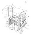
図1は、本発明の好ましい実施形態で使用される基板処理装置の概略構成を示す斜透視図である。
図1に示すように、基板処理装置101では、基板の一例となるウエハ200を収納したカセット110が使用されている。基板処理装置101は筐体111を備えており、筐体111内部にはカセットステージ114が設置されている。カセット110は工場内搬送装置(図示せず)によってカセットステージ114上に搬入されたり、カセットステージ114上から搬出されたりするようになっている。FIG. 1 is a perspective view showing a schematic configuration of a substrate processing apparatus used in a preferred embodiment of the present invention.
As shown in FIG. 1, the
カセットステージ114は、工場内搬送装置によって、カセット110内のウエハ200が垂直姿勢となり、カセット110のウエハ出し入れ口が上方向を向くように載置される。カセットステージ114は、カセット110を筐体後方に右回り縦方向90°回転し、カセット110内のウエハ200が水平姿勢となり、カセット110のウエハ出し入れ口が筐体111の後方を向くように動作可能となるよう構成されている。 The
筐体111内の前後方向の略中央部には、カセット棚105が設置されており、カセット棚105は複数段複数列にて複数個のカセット110を保管するように構成されている。カセット棚105にはウエハ移載機構125の搬送対象となるカセット110が収納される移載棚123が設けられている。 A
カセットステージ114の上方には予備カセット棚107が設けられ、予備的にカセット110を保管するように構成されている。 A
カセットステージ114とカセット棚105との間には、カセット搬送装置118が設置されている。カセット搬送装置118は、カセット110を保持したまま昇降可能なカセットエレベータ118aと搬送機構としてのカセット搬送機構118bとで構成されている。カセット搬送装置118はカセットエレベータ118aとカセット搬送機構118bとの連続動作により、カセットステージ114とカセット棚105と予備カセット棚107との間で、カセット110を搬送するように構成されている。 A cassette carrying
カセット棚105の後方にはウエハ移載機構125が設置されている。ウエハ移載機構125は、ウエハ200を水平方向に回転ないし直動可能なウエハ移載装置125aと、ウエハ移載装置125aを昇降させるためのウエハ移載装置エレベータ125bとで構成されている。ウエハ移載装置エレベータ125bは、耐圧筐体111の右側端部に設置されている。ウエハ移載機構125はウエハ移載装置エレベータ125bおよびウエハ移載装置125aの連続動作により、ウエハ移載装置125aのツイーザ125cをウエハ200の載置部として、ボート217に対してウエハ200を装填(チャージング)および脱装(ディスチャージング)するように構成されている。 A
筐体111の後部上方には、処理炉202が設けられている。処理炉202の下端部は、炉口シャッタ147により開閉されるように構成されている。 A
処理炉202の下方にはボート217を処理炉202に昇降させるボートエレベータ115が設けられている。ボートエレベータ115の昇降台に連結された連結具としてのアーム128には蓋体としてのシールキャップ219が水平に据え付けられている。シールキャップ219はボート217を垂直に支持し、処理炉202の下端部を閉塞可能なように構成されている。 Below the
ボート217は複数本の保持部材を備えており、複数枚(例えば、50枚〜150枚程度)のウエハ200をその中心を揃えて垂直方向に整列させた状態で、それぞれ水平に保持するように構成されている。 The
カセット棚105の上方には、清浄化した雰囲気であるクリーンエアを供給するよう、供給ファン及び防塵フィルタで構成されたクリーンユニット134aが設けられている。クリーンユニット134aは供給ファン及び防塵フィルタによりクリーンエアを筐体111の内部に流通させるように構成されている。 Above the
ウエハ移載装置エレベータ125bおよびボートエレベータ115側と反対側である筐体111の左側端部には、クリーンエアを供給するよう供給フアンおよび防塵フィルタで構成されたクリーンユニット134bが設置されている。クリーンユニット134bから吹き出されたクリーンエアは、ウエハ移載装置125a、ボート217などの周辺を流通した後に、図示しない排気装置に吸い込まれて、筐体111の外部に排気されるようになっている。 A
次に、基板処理装置101の動作について説明する。
工場内搬送装置(図示せず)によってカセット110がカセットステージ114上に搬入されると、カセット110は、ウエハ200がカセットステージ114の上で垂直姿勢を保持し、カセット110のウエハ出し入れ口が上方向を向くように載置される。その後、カセット110は、カセットステージ114によって、カセット110内のウエハ200が水平姿勢となり、カセット110のウエハ出し入れ口が筐体後方を向けるように、筐体後方に右周り縦方向90°回転させられる。Next, the operation of the
When the
その後、カセット110は、カセット棚105ないし予備カセット棚107の指定された棚位置へカセット搬送装置118によって自動的に搬送され受け渡され、一時的に保管された後、カセット棚105ないし予備カセット棚107からカセット搬送装置118によって移載棚123に移載されるか、もしくは直接移載棚123に搬送される。 Thereafter, the
カセット110が移載棚123に移載されると、ウエハ200はカセット110からウエハ移載装置125aのツイーザ125cによってウエハ出し入れ口を通じてピックアップされ、移載室(図示せず)の後方にあるボート217に装填(チャージング)される。ボート217にウエハ200を受け渡したウエハ移載装置125aはカセット110に戻り、後続のウエハ200をボート217に装填する。 When the
予め指定された枚数のウエハ200がボート217に装填されると、炉口シャッタ147によって閉じられていた処理炉202の下端部が、炉口シャッタ147によって開放される。その後、多数枚のウエハ200を保持したボート217は、シールキャップ219がボートエレベータ115によって上昇されることにより、処理炉202内へ搬入(ローディング)される。 When a predetermined number of
ローディング後は、処理炉202にてウエハ200に任意の処理(後述参照)が実施される。その処理後は、上述の逆の手順で、ウエハ200およびカセット110は筐体111の外部へ払出される。 After loading, arbitrary processing (see later) is performed on the
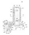
図2は、本発明の好ましい実施形態で使用される処理炉とそれに付属する部材との概略構成図であり、特に処理炉部分を縦断面で示している。図3は図2のA−A線断面図である。 FIG. 2 is a schematic configuration diagram of a processing furnace and members attached thereto used in a preferred embodiment of the present invention, and particularly shows a processing furnace portion in a longitudinal section. 3 is a cross-sectional view taken along line AA in FIG.
図2及び図3に示すように、処理炉202には加熱装置として機能するヒータ207が設けられている。ヒータ207の内側にはウエハ200を処理する反応管203が設けられている。反応管203の下端には、気密部材であるOリング220を介してステンレス等で構成されたマニホールド209が設けられている。マニホールド209の下端開口は、Oリング220を介して蓋体としてのシールキャップ219により気密に閉塞されている。処理炉202では、少なくとも、反応管203、マニホールド209及びシールキャップ219により処理室201が形成されている。 As shown in FIGS. 2 and 3, the
シールキャップ219にはボート支持台218を介してボート217が立設されている。ボート支持台218はボート217を保持する保持体となっており、ボート217を保持しながら処理室201に挿入するようになっている。ボート217にはバッチ処理される複数枚のウエハ200が水平姿勢で管軸方向に多段に積載されている。ヒータ207は処理室201に挿入されたウエハ200を所定の温度に加熱するようになっている。 A
処理室201へは複数種類(本実施形態では2種類)の処理ガスを供給する2本のガス供給管(ガス供給管232a,ガス供給管232b)が設けられている。 Two gas supply pipes (a
ガス供給管232aには上流方向から順に液体用のマスフローコントローラ240、気化器300及びバルブ243aが設けられている。 The
気化器300の内部において、ガス供給管232aにはバルブ301と気化部302とが設けられており、バルブ301が気化部302より上流側に配置され、気化部302がバルブ301より下流側に配置されている。気化部302はバルブ301を介して流通してきた処理ガスを常温・常圧で気化させる部位である。 Inside the
ガス供給管232aのバルブ301と気化部302との間には、気化器300(詳しくは気化部302)にキャリアガスを供給するキャリアガス供給管310が連結されている。キャリアガス供給管310にはバルブ311が設けられている。バルブ311は気化器300の外部に設けられている。バルブ311は気化器300の内部に設けられてもよい。 A carrier
ガス供給管232aの先端部にはノズル233aが設けられている。ノズル233aは、処理室201を構成している反応管203の内壁とウエハ200との間における円弧状の空間で、反応管203の内壁に沿った上下方向に延在している。ノズル233aの側面には、処理ガスを供給する多数のガス供給孔248aが設けられている。ガス供給孔248aは、下部から上部にわたってそれぞれ同一の開口面積を有し、更に同じ開口ピッチで設けられている。 A
ガス供給管232aにはキャリアガスを供給するキャリアガス供給管234aが連結されている。キャリアガス供給管234aには上流方向から順にマスフローコントローラ241bとバルブ243cとが設けられている。 A carrier
他方、ガス供給管232bには上流方向から順にマスフローコントローラ241aとバルブ243bとが設けられている。 On the other hand, the
ガス供給管232bの先端部にはノズル233bが設けられている。ノズル233bも、ノズル233aと同様に、処理室201を構成している反応管203の内壁とウエハ200との間における円弧状の空間で、反応管203の内壁に沿った上下方向に延在している。ノズル233bの側面には、処理ガスを供給する多数のガス供給孔248bが設けられている。ガス供給孔248bは、下部から上部にわたってそれぞれ同一の開口面積を有し、更に同じ開口ピッチで設けられている。 A
ガス供給管232bにはキャリアガスを供給するキャリアガス供給管234bが連結されている。キャリアガス供給管234bには上流方向から順にマスフローコントローラ241cとバルブ243dとが設けられている。 A carrier
上記構成では、ガス供給管232aに液体原料が導入されるようになっており、実際にその液体原料がガス供給管232aに流入すると、当該液体原料は液体用のマスフローコントローラ240に流量制御されながら気化器300に至り、気化器300で気化され、その気化ガスがノズル233aを介して処理室201内に供給されるようになっている。 In the above configuration, the liquid source is introduced into the
他方、ガス供給管232bには気体原料(処理ガス)が導入されるようになっており、実際にその処理ガスがガス供給管232bに流入すると、当該処理ガスはマスフローコントローラ241aに流量調整されながらガス供給管232bを流通し、最終的にノズル233bを介して処理室201に供給されるようになっている。 On the other hand, a gas raw material (processing gas) is introduced into the
処理室201にはバルブ243eを介してガスを排気するガス排気管231が接続されている。ガス排気管231には真空ポンプ246が接続されており、真空ポンプ246の作動で処理室201内を真空排気することができるようになっている。
なお、バルブ243eは弁を開閉して処理室201の真空排気・真空排気停止ができ、更に弁開度を調節して圧力調整可能となっている開閉弁である。A
The
反応管203内の中央部には、複数枚のウエハ200を多段に同一間隔で載置するボート217が設けられている。ボート217は、ボートエレベータ115により反応管203に出入りすることができるようになっている。ボート217の下端部には、処理の均一性を向上するために当該ボート217を回転するためのボート回転機構267が設けられている。ボート回転機構267を駆動させることにより、ボート支持台218に支持されたボート217を回転させることができるようになっている。 A
制御部としてのコントローラ280は、液体用のマスフローコントローラ240と、マスフローコントローラ241a,241b,241cと、バルブ243a,243b,243c,243d,243e,301,311と、ヒータ207と、真空ポンプ246と、ボート回転機構267と、ボートエレベータ115とに接続されている。 The
コントローラ280は、液体マスフローコントローラ240の流量調整と、マスフローコントローラ241a,241b,241cの流量調整と、バルブ243a,243b,243c,243d,301,311の開閉動作と、バルブ243eの開閉及び圧力調整動作と、ヒータ207の温度調整と、真空ポンプ246の起動・停止と、ボート回転機構267の回転速度調節と、ボートエレベータ115の昇降動作とを、制御するようになっている。 The
次に、ALD法を用いた成膜処理例について、半導体デバイスの製造工程の一つである、TEMAHとO3とを用いてHfO2膜を成膜する例を基に説明する。Next, an example of a film formation process using the ALD method will be described based on an example of forming an HfO2 film using TEMAH and O3 , which is one of the semiconductor device manufacturing steps.
CVD(Chemical Vapor Deposition)法の一つであるALD(Atomic Layer Deposition)法は、ある成膜条件(温度、時間等)の下で、成膜に用いる少なくとも2種類の原料となる処理ガスを1種類ずつ交互に基板上に供給し、1原子単位で基板上に吸着させ、表面反応を利用して成膜を行う手法である。このとき、膜厚の制御は、処理ガスを供給するサイクル数で行う(例えば、成膜速度が1Å/サイクルとすると、20Åの膜を形成する場合、20サイクル行う)。 An ALD (Atomic Layer Deposition) method, which is one of CVD (Chemical Vapor Deposition) methods, uses 1 process gas as at least two kinds of raw materials used for film formation under certain film formation conditions (temperature, time, etc.). In this method, the materials are alternately supplied onto the substrate, adsorbed onto the substrate in units of one atom, and a film is formed using a surface reaction. At this time, the film thickness is controlled by the number of cycles for supplying the processing gas (for example, if the film forming speed is 1 kg / cycle, 20 cycles are performed when a 20 mm film is formed).
ALD法では、例えばHfO2膜を形成する場合、TEMAH(Hf[NCH3C2H5]4,テトラキスメチルエチルアミノハフニウム)とO3(オゾン)とを用いて180〜250℃の低温で高品質の成膜が可能である。In the ALD method, for example, when an HfO2 film is formed, a high temperature is used at a low temperature of 180 to 250 ° C. using TEMAH (Hf [NCH3 C2 H5 ]4 , tetrakismethylethylaminohafnium) and O3 (ozone). Quality film formation is possible.
まず、上述したようにウエハ200をボート217に装填し、処理室201に搬入する。ボート217を処理室201に搬入したら、後述する4つのステップを順次実行する(下記では、キャリアガスとして不活性ガスの1種であるN2を用いている。)。First, as described above, the
(ステップ1)
真空ポンプ246を作動させた状態において、キャリアガス供給管232aにTEMAHを流入させかつキャリアガス供給管310とキャリアガス供給管234aとにそれぞれN2を流入させる。そして、ガス排気管231のバルブ243eと、ガス供給管232aのバルブ301,243aと、キャリアガス供給管310のバルブ311と、キャリアガス供給管234aのバルブ243cとを、開ける。(Step 1)
In a state where the
ガス供給管232aから流入した液体のTEMAHは、マスフローコントローラ240に流量調整されながら気化器300に至り、気化部302で気化される。キャリアガス供給管310から流入したN2は、バルブ301を介して気化器300の気化部302に至る。キャリアガス供給管234aから流入したN2は、マスフローコントローラ241bに流量調整されながら、ガス供給管232aとの連結部に至る。The liquid TEMAH that has flowed in from the
ここで、ステップ1では、キャリアガス供給管310内の圧力をガス供給管232a内の圧力よりも高く維持する。 Here, in step 1, the pressure in the carrier
バルブ301とバルブ311との開放動作においては、キャリアガス供給管310のバルブ311を先に開けてその後にガス供給管232aのバルブ301を開けるのが好ましい。気化部302で気化されたTEMAHの気化ガスがキャリアガス供給管310に流入するのを未然に回避することができるからである。 In the opening operation of the
そして気化器300で気化されたTEMAHの気化ガスは、気化器300から流出してキャリアガス供給管234aとの連結部でキャリアガス供給管234aから供給されたN2と合流し、その後はガス供給管232aを流通しながら処理室201に至り、最終的にノズル233aのガス供給孔248aから処理室201内に供給されガス排気管231から排気される。The vaporized gas of TEMAH vaporized in the
このとき、バルブ243eを適正に調整して処理室201内の圧力を一定範囲内の最適な値に維持する。液体用のマスフローコントローラ240で制御するTEMAHの供給量は0.01〜0.1g/minである。TEMAHの気化ガスをウエハ200に晒す時間は30〜180秒間である。このときヒータ207の温度はウエハ200の温度が180〜250℃の範囲内の最適な値になるよう設定してある。 At this time, the
以上のステップ1では、上記の通りにTEMAHの気化ガスを処理室201内に供給することで、ウエハ200上の下地膜などの表面部分と表面反応(化学吸着)する。 In Step 1 described above, the vaporized gas of TEMAH is supplied into the
(ステップ2)
キャリアガス供給管310内の圧力をガス供給管232a内の圧力よりも高く維持した状態において、ガス供給管232aのバルブ301,243aと、キャリアガス供給管310のバルブ311と、キャリアガス供給管234aのバルブ243cとを開じて、TEMAHの気化ガスの処理室201への供給を停止する。(Step 2)
In a state where the pressure in the carrier
ここで、3つのバルブ243a,301,311については、閉動作の順序を一定にする。
その順序の一例としては、最初に気化器300内のバルブ301を閉じ、その後にバルブ243aを閉じ、最後にキャリアガス供給管310のバルブ311を閉じる。その順序の他例としては、最初に気化器300内のバルブ301を閉じ、その後にキャリアガス供給管310のバルブ311を閉じ、最後にバルブ243aを閉じる。すなわち、ここでは、ガス供給管232aのバルブ301を閉じる動作を行う際には、キャリアガス供給管310のバルブ311が開放されていることを条件として、ガス供給管232aのバルブ301の閉動作を実行する。Here, the order of the closing operation is made constant for the three
As an example of the order, first, the
またステップ2では、ガス排気管231のバルブ243eは開いたままとし、真空ポンプ246により処理室201内を20Pa以下となるまで排気し、残留したTEMAHの気化ガスを処理室201内から排除する。
このとき、キャリアガス供給管234aのバルブ243cも開けたままとしてキャリアガス供給管234aからN2を処理室201内へ供給してもよく、この場合には、残留したTEMAHの気化ガスを更に排除する効果が高まる。In step 2, the
At this time, N2 may be supplied from the carrier
(ステップ3)
ガス供給管232bにO3を流入させかつキャリアガス供給管234bにN2を流入させる。この状態において、ガス供給管234bのバルブ243bと、キャリアガス供給管234bのバルブ243dとを、開ける。(Step 3)
O3 is allowed to flow into the
ガス供給管234bから流入したO3は、マスフローコントローラ241aに流量調整されながらキャリアガス供給管234bとの連結部に至る。キャリアガス供給管234bから流入したN2は、マスフローコントローラ241cに流量調整されながらガス供給管232bとの連結部に至る。ガス供給管232bとキャリアガス供給管234bとの連結部で、O3はN2と混合され、その後はガス供給管232bを流通しながら処理室201に至り、最終的にノズル233bのガス供給孔248bから処理室201内に供給されつつガス排気管231から排気される。The O3 flowing in from the
ステップ3では、バルブ243eを適正に調整して処理室201内の圧力を一定範囲内の最適な値に維持する。O3をウエハ200に晒す時間は10〜120秒間である。このときのウエハ200の温度は、ステップ1のTEMAHの気化ガスの供給時と同じく180〜250℃の範囲内の最適な温度となるようヒータ207を設定する。In step 3, the
以上のステップ3では、上記の通りにO3の処理ガスを処理室201に供給することで、ウエハ200の表面に化学吸着したTEMAHとO3とを反応させ、ウエハ200上にHfO2膜を成膜する。In the above step 3, as described above, the processing gas of O3 is supplied to the
(ステップ4)
成膜後、ガス供給管232bのバルブ243bと、キャリアガス供給管234bのバルブ243dとを閉じ、真空ポンプ246により処理室201内を真空排気し、残留したO3の成膜に寄与した後のガスを排除する。
このとき、キャリアガス供給管234bのバルブ243dを開いたままとしてキャリアガス供給管234bからN2を処理室201内に供給してもよく、この場合には、残留したO3の成膜に寄与した後の処理ガスを処理室201から排除する効果が高まる。(Step 4)
After the film formation, the
At this time, N2 may be supplied into the
以後、ステップ1〜4を1サイクルとしてこのサイクルを複数回繰り返すことにより、ウエハ200上に所定の膜厚のHfO2膜を成膜することができる。Thereafter, by repeating steps 1 to 4 as one cycle and repeating this cycle a plurality of times, a HfO2 film having a predetermined thickness can be formed on the
以上の本実施形態では、ステップ1でTEMAHの気化ガスを処理室201に供給する場合に、キャリアガス供給管310内の圧力をガス供給管232a内の圧力より高く維持し、キャリアガス供給管310内とガス供給管232a内とで圧力差を設けている。そのため、TEMAHの気化ガスがN2の圧力を受けてキャリアガス供給管310に流入し難い。In the above embodiment, when the TEMAH vaporized gas is supplied to the
加えて、ステップ2でTEMAHの気化ガスの供給を停止する場合には、ガス供給管232aのバルブ301とキャリアガス供給管310のバルブ311とを閉じる順序に関し、キャリアガス供給管310内の圧力をガス供給管232a内の圧力よりも高く維持したまま、バルブ311が開放されていることを条件としてバルブ301を開放している。この場合、キャリアガス供給管310にN2が充満している状態でTEMAHの気化ガスの供給が停止され、当該TEMAHの気化ガスはそのN2の存在でキャリアガス供給管310には流入し難い。In addition, when the supply of the vaporized TEMAH gas is stopped in step 2, the pressure in the carrier
以上から、TEMAHの気化ガスがキャリアガス供給管310に流入するのを防止又は抑止することができ、ひいてはキャリアガス供給管310を閉塞したりゴミを発生させたりするのを防止又は抑制することができ、処理室201内でHfO2膜を良好に形成することできる。From the above, it is possible to prevent or suppress the TEMAH vaporized gas from flowing into the carrier
101 基板処理装置
200 ウエハ
201 処理室
202 処理炉
203 反応管
207 ヒータ
209 マニホールド
217 ボート
218 ボート支持台
219 シールキャップ
220 Oリング
231 ガス排気管
232a,232b ガス供給管
233a,233b ノズル
234a,234b キャリアガス供給管
240 液体用のマスフローコントローラ
241a,241b,241c マスフローコントローラ
243a,243b,243c,243d,243e バルブ
246 真空ポンプ
248a,248b ガス供給孔
267 ボート回転機構
280 コントローラ
300 気化器
301 バルブ
302 気化部
310 キャリアガス供給管
311 バルブDESCRIPTION OF
Claims (1)
Translated fromJapanese前記基板を加熱する加熱手段と、
前記処理室内に所望の処理ガスを供給するガス供給系と、
前記処理室内の雰囲気を排気するガス排気系と、
制御部と、
を備え、
前記ガス供給系は、液体の原料を気化させる気化ユニットを含み、
前記気化ユニットは、第1のバルブを介して接続されるキャリアガス供給ラインと、第2のバルブを介して接続される液体原料供給ラインとを、含み、
前記制御部は、前記キャリアガス供給ライン内の圧力を液体原料供給ライン内の圧力よりも高く維持させ、且つ、前記第2のバルブを閉じる動作を行う際は、前記第1のバルブが開放されていることを条件に閉動作を実行することを特徴とする基板処理装置。A processing chamber for accommodating the substrate;
Heating means for heating the substrate;
A gas supply system for supplying a desired processing gas into the processing chamber;
A gas exhaust system for exhausting the atmosphere in the processing chamber;
A control unit;
With
The gas supply system includes a vaporization unit that vaporizes a liquid raw material,
The vaporization unit includes a carrier gas supply line connected via a first valve and a liquid source supply line connected via a second valve,
The control unit maintains the pressure in the carrier gas supply line higher than the pressure in the liquid source supply line, and when performing the operation of closing the second valve, the first valve is opened. A substrate processing apparatus that performs a closing operation on condition that
Priority Applications (1)
| Application Number | Priority Date | Filing Date | Title |
|---|---|---|---|
| JP2007065059AJP2008227261A (en) | 2007-03-14 | 2007-03-14 | Substrate processing equipment |
Applications Claiming Priority (1)
| Application Number | Priority Date | Filing Date | Title |
|---|---|---|---|
| JP2007065059AJP2008227261A (en) | 2007-03-14 | 2007-03-14 | Substrate processing equipment |
Publications (1)
| Publication Number | Publication Date |
|---|---|
| JP2008227261Atrue JP2008227261A (en) | 2008-09-25 |
Family
ID=39845508
Family Applications (1)
| Application Number | Title | Priority Date | Filing Date |
|---|---|---|---|
| JP2007065059APendingJP2008227261A (en) | 2007-03-14 | 2007-03-14 | Substrate processing equipment |
Country Status (1)
| Country | Link |
|---|---|
| JP (1) | JP2008227261A (en) |
- 2007
- 2007-03-14JPJP2007065059Apatent/JP2008227261A/enactivePending
Similar Documents
| Publication | Publication Date | Title |
|---|---|---|
| JP4879041B2 (en) | Substrate processing equipment | |
| JP5295399B2 (en) | Semiconductor device manufacturing method, substrate processing method, and substrate processing apparatus | |
| KR101232688B1 (en) | Substrate processing apparatus, method of manufacturing semiconductor device, and method of confirming operation of liquid flowrate control device | |
| JP2008258595A (en) | Substrate processing equipment | |
| JP2012212854A (en) | Substrate processing device and solid raw material replenishing method | |
| JP2011252221A (en) | Manufacturing method of semiconductor device and substrate treatment apparatus | |
| JP2010118462A (en) | Substrate processing apparatus | |
| JP4836761B2 (en) | Manufacturing method of semiconductor device | |
| JP5344663B2 (en) | Substrate processing apparatus, semiconductor device manufacturing method, and substrate processing method | |
| JP4874984B2 (en) | Substrate processing equipment | |
| JP4903619B2 (en) | Substrate processing equipment | |
| JP2006286716A (en) | Manufacturing method of semiconductor device | |
| JP2009224588A (en) | Substrate treatment apparatus | |
| JP2009123950A (en) | Substrate processing equipment | |
| JP2009224457A (en) | Substrate treating apparatus | |
| JP2011187485A (en) | Substrate processing apparatus | |
| JP2012138530A (en) | Substrate manufacturing method, semiconductor device manufacturing method and substrate processing apparatus | |
| JP2012009744A (en) | Substrate treatment apparatus | |
| JP2008160081A (en) | Substrate processing apparatus and substrate processing method | |
| JP2011054590A (en) | Substrate processing apparatus | |
| JP2007194331A (en) | Substrate processing equipment | |
| JP2007227471A (en) | Substrate processing equipment | |
| JP2008227261A (en) | Substrate processing equipment | |
| JP5273936B2 (en) | Substrate processing apparatus and semiconductor device manufacturing method | |
| JP4963817B2 (en) | Substrate processing equipment |
Legal Events
| Date | Code | Title | Description |
|---|---|---|---|
| RD05 | Notification of revocation of power of attorney | Free format text:JAPANESE INTERMEDIATE CODE: A7425 Effective date:20100204 | |
| RD04 | Notification of resignation of power of attorney | Free format text:JAPANESE INTERMEDIATE CODE: A7424 Effective date:20100210 |