JP2008219671A - Signal transmission method, transmitter and receiver - Google Patents
Signal transmission method, transmitter and receiverDownload PDFInfo
- Publication number
- JP2008219671A JP2008219671AJP2007056443AJP2007056443AJP2008219671AJP 2008219671 AJP2008219671 AJP 2008219671AJP 2007056443 AJP2007056443 AJP 2007056443AJP 2007056443 AJP2007056443 AJP 2007056443AJP 2008219671 AJP2008219671 AJP 2008219671A
- Authority
- JP
- Japan
- Prior art keywords
- sequence
- iota
- pilot
- symbol
- transmission
- Prior art date
- Legal status (The legal status is an assumption and is not a legal conclusion. Google has not performed a legal analysis and makes no representation as to the accuracy of the status listed.)
- Granted
Links
Images


Classifications
- Y—GENERAL TAGGING OF NEW TECHNOLOGICAL DEVELOPMENTS; GENERAL TAGGING OF CROSS-SECTIONAL TECHNOLOGIES SPANNING OVER SEVERAL SECTIONS OF THE IPC; TECHNICAL SUBJECTS COVERED BY FORMER USPC CROSS-REFERENCE ART COLLECTIONS [XRACs] AND DIGESTS
- Y02—TECHNOLOGIES OR APPLICATIONS FOR MITIGATION OR ADAPTATION AGAINST CLIMATE CHANGE
- Y02D—CLIMATE CHANGE MITIGATION TECHNOLOGIES IN INFORMATION AND COMMUNICATION TECHNOLOGIES [ICT], I.E. INFORMATION AND COMMUNICATION TECHNOLOGIES AIMING AT THE REDUCTION OF THEIR OWN ENERGY USE
- Y02D30/00—Reducing energy consumption in communication networks
- Y02D30/70—Reducing energy consumption in communication networks in wireless communication networks
Landscapes
- Radio Transmission System (AREA)
Abstract
Translated fromJapaneseDescription
Translated fromJapanese本発明は、広くは無線通信技術に関し、特に、既知信号を用いてチャネル推定を行う無線通信システムにおいて、既知信号の処理を含む信号伝送方法と、これを実行する送信機および受信機構成に関する。 The present invention relates generally to wireless communication technology, and more particularly to a signal transmission method including processing of a known signal and a transmitter and receiver configuration for executing the same in a wireless communication system that performs channel estimation using a known signal.
携帯電話等の移動端末の普及にともなって、データサービスに対する需要が急激に増大している。このような需要に応じて、移動通信ネットワークでより低コストかつ高速データレートのサービスを提供するためには、無線チャネル帯域の超広帯域化(ブロードバンド化)が有効であると考えられる。ブロードバンド通信で高品質な信号伝送を実現するためには、遅延波からの干渉(マルチパス干渉)を抑制することが重要な課題となる。 With the spread of mobile terminals such as mobile phones, the demand for data services is increasing rapidly. In response to such demand, in order to provide a service with a lower cost and a higher data rate in a mobile communication network, it is considered effective to make the radio channel band ultra-wideband (broadband). In order to realize high-quality signal transmission in broadband communication, it is important to suppress interference from delayed waves (multipath interference).
マルチパス干渉に対する耐性の大きい無線アクセス方式として、直交周波数分割多重(OFDM:Orthogonal Frequency Division Multiplexing)無線アクセスが注目され、多くの検討がなされている。OFDMでは、チャネル帯域を、互いに直交する多数の低速レートのサブキャリアに分割して伝送を行う。このとき、遅延波によるシンボル間干渉(ISI:Inter-Symbol Interference)や、キャリア間干渉(ICI:Inter-Carrier Interference)を抑圧するため,OFDMシンボル毎にガード区間(ガードインターバル)を挿入するのが一般的である。 Orthogonal frequency division multiplexing (OFDM) radio access has attracted attention as a radio access scheme with high resistance against multipath interference, and many studies have been made. In OFDM, transmission is performed by dividing a channel band into a number of low-rate subcarriers orthogonal to each other. At this time, in order to suppress inter-symbol interference (ISI) and inter-carrier interference (ICI) due to delayed waves, a guard interval (guard interval) is inserted for each OFDM symbol. It is common.
一方、ガード区間を用いずに、シンボル間干渉やキャリア間干渉を抑制する送信方法として、Offset QAM(OQAM)とIOTA(Isotropic Orthogonal Transform Algorithm)フィルタの適用(以下、適宜OQAM/IOTAと省略する)が提案されている(たとえば、非特許文献1参照)。 On the other hand, an offset QAM (OQAM) and an IOTA (Isotropic Orthogonal Transform Algorithm) filter are applied as a transmission method for suppressing inter-symbol interference and inter-carrier interference without using a guard interval (hereinafter abbreviated as OQAM / IOTA as appropriate). Has been proposed (see Non-Patent
OQAMでは、コンステレーション上で、Q軸に適用される信号と、I軸に適用される信号を、1/2シンボル区間ずらして交互に配置して、キャリアの消失を防止する。このように複素変調した信号をIOTAフィルタ処理する。IOTAフィルタの直交変換アルゴリズムは時間と周波数のドメインで信号をより局在化できるので、シンボル間干渉の低減に有効である。 In OQAM, on the constellation, a signal applied to the Q-axis and a signal applied to the I-axis are alternately arranged while being shifted by a ½ symbol period to prevent carrier loss. The complex-modulated signal is subjected to IOTA filter processing. The orthogonal transform algorithm of the IOTA filter can effectively localize the signal in the time and frequency domains, and is effective in reducing intersymbol interference.
図1Aは、OQAM/IOTAを適用するOFDMの概念図である。OQAM/IOTAは、ガード区間を必要としないため、データレートの観点からはガード区間を設ける方法と比較して有利であるが、以下のような問題点がある。すなわち、コンステレーション上で希望信号と直交する成分に対して、図1Aに示すように、隣接するOFDMシンボル、サブキャリアからの信号の洩れ込みによる干渉が発生する。この干渉成分は、あくまで希望信号と直交する成分のみに限定されるため、チャネル推定値が得られた後の同期検波の際には、通常問題となることはない。しかし、パイロット信号を用いたチャネル推定を行う際にこのような干渉成分が存在すると(すなわち、図1Aのパイロットシンボルのように、隣接するOFDMシンボルやサブキャリアからの干渉があると)、正確にチャネル推定を行うことが困難となる。 FIG. 1A is a conceptual diagram of OFDM to which OQAM / IOTA is applied. Since OQAM / IOTA does not require a guard interval, it is more advantageous than the method of providing a guard interval from the viewpoint of the data rate, but has the following problems. That is, as shown in FIG. 1A, interference due to leakage of signals from adjacent OFDM symbols and subcarriers occurs for components orthogonal to the desired signal on the constellation. Since this interference component is limited only to a component orthogonal to the desired signal, it does not normally cause a problem in the synchronous detection after the channel estimation value is obtained. However, when such an interference component is present when performing channel estimation using a pilot signal (that is, when there is interference from an adjacent OFDM symbol or subcarrier as in the pilot symbol of FIG. 1A), it is accurate. It becomes difficult to perform channel estimation.
これを解決するために、図1Bに示すように、パイロットシンボルと隣接するOFDMシンボル、サブキャリアにおいて、干渉を打ち消すための信号を適応的に挿入する方法が提案されている(たとえば、非特許文献2参照)。しかしながら、この方法では、干渉打ち消し用の信号に大きな電力を要するので、送信電力のロスを考慮すると、ガード区間を不要としたメリットを十分に活用することができず、根本的な問題解決には至っていない。
上記の問題点に鑑みて、本発明は、OQAM/IOTAを適用する無線通信において、オーバヘッドを増大させることなく、パイロット信号への干渉の混入を防止し、正確なチャネル推定を可能にする信号伝送方法を提供することを課題とする。 In view of the above problems, the present invention provides signal transmission that prevents interference from being mixed into a pilot signal and enables accurate channel estimation without increasing overhead in wireless communication using OQAM / IOTA. It is an object to provide a method.
また、そのような信号伝送方法を実現する送信機構成と受信機構成を提供することを課題とする。 It is another object of the present invention to provide a transmitter configuration and a receiver configuration that realize such a signal transmission method.
上記課題を解決するために、実施形態では、送信側で、パイロットシンボルが存在する領域(区間)と、データシンボルが存在する領域(区間)を分離し、各々の領域で信号波形の折り返し処理を行うことによって、各領域を他方の領域からの干渉の影響を排除した閉じた領域とし、パイロットシンボル区間でのシンボル間の干渉を、既知の信号のみとする。 In order to solve the above-described problem, in the embodiment, on the transmission side, an area (section) where pilot symbols exist and an area (section) where data symbols exist are separated, and signal waveform folding processing is performed in each area. By doing so, each region is a closed region in which the influence of interference from the other region is eliminated, and interference between symbols in the pilot symbol period is limited to a known signal.
ここで、送信側の折り返し処理とは、送信すべきシンボル系列(たとえばパイロットシンボル系列)のIOTAフィルタ出力波形のうち、後続するシンボル領域(たとえばデータシンボル領域)に影響する部分を切り取って、IOTA出力波形の先頭部分に加算する処理をいう。これによって、パイロットシンボル系列とデータシンボル系列の送信信号系列は、それぞれの区間で閉じたものとなる。パイロット信号は、送信側でも受信側でも既知の信号なので、上記の折り返し処理後は、パイロット区間内でのシンボル間干渉は、既知の信号のみによるものとなる。その結果、受信側でのチャネル推定が容易になる。 Here, the return processing on the transmission side means that the IOTA output of the symbol sequence (for example, pilot symbol sequence) to be transmitted is cut out from the IOTA filter output waveform that affects the subsequent symbol region (for example, data symbol region). The process of adding to the top of the waveform. As a result, the transmission signal sequences of the pilot symbol sequence and the data symbol sequence are closed in the respective sections. Since the pilot signal is a known signal on both the transmitting side and the receiving side, inter-symbol interference within the pilot interval is caused only by the known signal after the above-described aliasing process. As a result, channel estimation on the receiving side is facilitated.
より具体的には、本発明の第1の側面では、信号伝送方法は
(a)伝送すべきパイロットシンボル系列とデータシンボル系列を、時間ドメインまたは周波数ドメインの少なくとも一方において互いに分離し、
(b)前記パイロットシンボル系列とデータシンボル系列の各々に対して、オフセットQAMとIOTA(Isotropic Orthogonal Transform Algorithm)フィルタ処理を行い、
(c)前記パイロットシンボル系列と前記データシンボル系列の各々について、後続するシンボル領域に影響する部分のIOTAフィルタ出力成分を切り取って、当該IOTAフィルタ出力の先頭部分に加算する折り返し処理を行う、
工程を含む。More specifically, in the first aspect of the present invention, the signal transmission method (a) separates a pilot symbol sequence and a data symbol sequence to be transmitted from each other in at least one of the time domain and the frequency domain,
(B) performing an offset QAM and IOTA (Isotropic Orthogonal Transform Algorithm) filter processing on each of the pilot symbol sequence and the data symbol sequence;
(C) For each of the pilot symbol series and the data symbol series, a loopback process is performed to cut out a portion of the IOTA filter output component that affects the subsequent symbol area and add it to the head portion of the IOTA filter output.
Process.
この手法により、ガードインターバルの付加や、干渉キャンセル用の信号の挿入を不要としつつ、パイロット信号への未知の信号からの干渉の影響を排除して、チャネル推定精度を向上することができる。 By this method, it is possible to improve the channel estimation accuracy by eliminating the influence of interference from an unknown signal on the pilot signal while eliminating the need for adding a guard interval or inserting a signal for canceling interference.
良好な実施例では、パイロットシンボル系列のシンボル数をnとすると、1シンボル当たりのIOTAフィルタのサンプル数はnTであり、nシンボルのパイロットシンボル系列については、各シンボルにつき、時間Tだけずれて出力されるので、IOTAフィルタ出力波形のトータルのサンプル数は(2n−1)Tとなる。 In the preferred embodiment, if the number of symbols in the pilot symbol sequence is n, the number of samples of the IOTA filter per symbol is nT, and the pilot symbol sequence of n symbols is output shifted by time T for each symbol. Therefore, the total number of samples of the IOTA filter output waveform is (2n-1) T.
前記折り返し処理において、前記パイロットシンボル系列のIOTAフィルタ出力波形のうち、nTサンプルを越える部分、すなわち最後の(n−1)Tサンプル分を切り取って、このIOTAフィルタ出力波形の先頭部分に加算してnTサンプル長の送信信号系列を生成する。 In the loopback processing, a portion exceeding the nT samples, that is, the last (n-1) T samples in the IOTA filter output waveform of the pilot symbol series is cut out and added to the head portion of the IOTA filter output waveform. A transmission signal sequence having an nT sample length is generated.
上述した送信信号系列を受信する側では、受信した送信信号系列の先頭部分を、当該送信信号系列の後ろにコピーする受信側折り返し処理を行い、受信側折り返し処理をした信号系列から送信シンボル系列を取り出す。 On the side that receives the transmission signal sequence described above, a reception side loop-back process is performed to copy the head portion of the received transmission signal sequence after the transmission signal sequence, and a transmission symbol sequence is obtained from the signal sequence that has been subjected to the reception-side loop back process. Take out.
たとえば、nTサンプル長の送信信号系列を受信した場合、受信した送信信号系列の先頭の(n−1)Tサンプル分を、この送信信号系列の後ろにコピーして(2n−1)Tサンプルの送信信号系列を再生し、(2n−1)Tサンプルの送信信号系列から、nシンボルのシンボル系列を取り出す。 For example, when a transmission signal sequence having an nT sample length is received, the first (n-1) T samples of the received transmission signal sequence are copied behind this transmission signal sequence to obtain (2n-1) T samples. A transmission signal sequence is reproduced, and a symbol sequence of n symbols is extracted from the transmission signal sequence of (2n-1) T samples.
本発明の第2の側面では、上述の信号伝送方法を実行する送信機を提供する。この送信機は、
(a)送信すべきパイロットシンボル系列と、データシンボル系列の各々にOQAM変調を施すオフセット部と、
(b)前記OQAM変調されたパイロットシンボル系列およびデータシンボル系列の各々に対してIOTAフィルタ処理を行うIOTAフィルタ部と、
(c)前記IOTAフィルタ処理されたパイロットシンボル系列およびデータシンボル系列の各々に対して、前記IOTAフィルタ出力波形のうち、後続するシンボル領域に影響する部分を切り取って、当該IOTAフィルタ出力波形の先頭部分に加算して送信信号系列を生成する折り返し処理部と、
を備える。In a second aspect of the present invention, a transmitter for executing the above-described signal transmission method is provided. This transmitter
(A) a pilot symbol sequence to be transmitted, an offset unit that performs OQAM modulation on each of the data symbol sequences,
(B) an IOTA filter unit that performs an IOTA filter process on each of the OQAM modulated pilot symbol sequence and data symbol sequence;
(C) For each of the pilot symbol sequence and data symbol sequence subjected to the IOTA filter processing, a portion of the IOTA filter output waveform that affects the subsequent symbol area is cut out, and the leading portion of the IOTA filter output waveform A folding processing unit for generating a transmission signal sequence by adding to
Is provided.
本発明の第3の側面では、上述した送信機に対応する処理を行う受信機を提供する。受信機は、
(a)無線チャネルで送られてくるパイロット信号系列を蓄積する受信バッファと、
(b)前記受信されたパイロット信号系列のうち、先頭部分の受信信号成分を、当該受信パイロット信号系列の後ろにコピーして受信側折り返し処理を行う折り返し処理部と、
(c)前記折り返し処理をした受信パイロット信号系列から、送信パイロットシンボル系列を取り出す受信側IOTAフィルタ部と、
(d)前記IOTAフィルタ部の出力に基づいてチャネル推定を行うチャネル推定部と、
を備える。In the 3rd side surface of this invention, the receiver which performs the process corresponding to the transmitter mentioned above is provided. The receiver
(A) a reception buffer for accumulating a pilot signal sequence transmitted through a radio channel;
(B) a loop-back processing unit that copies a reception signal component at the beginning of the received pilot signal sequence to the back of the received pilot signal sequence and performs reception-side loop processing;
(C) a reception-side IOTA filter unit that extracts a transmission pilot symbol sequence from the reception pilot signal sequence subjected to the loopback process;
(D) a channel estimation unit that performs channel estimation based on the output of the IOTA filter unit;
Is provided.
これらの送信機や受信機は、MIMO伝送にも適応可能である。 These transmitters and receivers can also be adapted for MIMO transmission.
OFDM方式の無線通信において、容易かつ正確にチャネル推定を行うことが可能になる。また、送信電力ロスを抑制して、高効率な無線通信が実現される。 In OFDM wireless communication, channel estimation can be performed easily and accurately. In addition, transmission power loss is suppressed, and highly efficient wireless communication is realized.
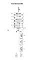
以下で、本発明の良好な実施形態について、図面を参照して説明する。図2は、本発明の一実施形態に係るパイロットシンボル系列とデータシンボル系列の分離の概念を示す図である。本実施形態では、信号伝送の際に、パイロットシンボル領域とデータシンボル領域を分離して、任意のパイロットシンボルに対するデータシンボルからの干渉の影響を低減する。図2に示す時間/周波数ドメイン図では、黒の四角で表されるパイロットシンボルの区間と、白の四角で表されるデータシンボルの区間は、時間領域で分割されているが、周波数領域で分割する構成としてもよい。 Hereinafter, preferred embodiments of the present invention will be described with reference to the drawings. FIG. 2 is a diagram illustrating a concept of separation of a pilot symbol sequence and a data symbol sequence according to an embodiment of the present invention. In this embodiment, at the time of signal transmission, the pilot symbol area and the data symbol area are separated to reduce the influence of interference from data symbols on an arbitrary pilot symbol. In the time / frequency domain diagram shown in FIG. 2, the pilot symbol section represented by a black square and the data symbol section represented by a white square are divided in the time domain, but are divided in the frequency domain. It is good also as composition to do.
このようなパイロット構成とすることで、コンステレーション上で希望信号と直交する成分に対する、隣接する複数のOFDMシンボル、サブキャリアからの漏れ込みによる干渉を大幅に低減することができる。 By adopting such a pilot configuration, interference due to leakage from a plurality of adjacent OFDM symbols and subcarriers with respect to a component orthogonal to the desired signal on the constellation can be significantly reduced.
もっとも、パイロットシンボル区間とデータシンボル区間の境界に位置するシンボルについては、互いに隣接するシンボルからの干渉成分が混入する可能性を否定できない。そこで、以下で説明するように、パイロットシンボル領域と、データシンボル領域の各々で折り返し処理を行うことによって、各シンボル領域を閉じた区間として分離し、他のシンボル領域への干渉成分の混入を防止する。この方法によれば、パイロットシンボル区間では、シンボル間の干渉を既知の信号のみに限定することができるので、チャネル推定が容易になる。 However, for symbols located at the boundary between the pilot symbol period and the data symbol period, the possibility that interference components from adjacent symbols are mixed cannot be denied. Therefore, as described below, each symbol area is separated as a closed section by performing a loopback process in each of the pilot symbol area and the data symbol area, thereby preventing interference components from being mixed into other symbol areas. To do. According to this method, in the pilot symbol section, interference between symbols can be limited to only known signals, so that channel estimation is facilitated.
次に、図3〜図5を参照して、パイロットシンボル領域とデータシンボル領域の分離を実現する具体的な手法を説明する。 Next, a specific method for realizing the separation of the pilot symbol area and the data symbol area will be described with reference to FIGS.
図3は、本発明の一実施形態の信号処理を説明するための図であり、送信側でのパイロット信号処理の際のIOTAフィルタ出力を示す図である。実施形態では、OFDM無線アクセス方式において、ガード区間を挿入せずに、OQAM(Offset QAM)/IOTAを適用することによって、キャリア間、シンボル間の干渉を低減する。 FIG. 3 is a diagram for explaining signal processing according to an embodiment of the present invention, and is a diagram illustrating an IOTA filter output at the time of pilot signal processing on the transmission side. In the embodiment, in the OFDM radio access scheme, interference between carriers and symbols is reduced by applying OQAM (Offset QAM) / IOTA without inserting a guard interval.
図3(a)に示すように、IOTA関数は、最適に局在化されたガウス関数の形状を有する。この例では、処理すべきパイロットシンボルの数がnシンボルなので、IOTAフィルタのサンプル数はnTであり、1つのシンボルは、nTサンプルのタイムデュレーションに変換される。 As shown in FIG. 3A, the IOTA function has the shape of an optimally localized Gaussian function. In this example, since the number of pilot symbols to be processed is n symbols, the number of samples of the IOTA filter is nT, and one symbol is converted into a time duration of nT samples.
図3(b)に示すように、パイロットシンボル区間でのパイロットシンボル数をnとして、nシンボルのパイロットシンボル系列にIOTAフィルタフィルタ処理を行うと、2つめのパイロットシンボルのIOTAフィルタ出力は、1つめのパイロットシンボルよりも時間Tだけ遅れて出力され、n番目のパイロットシンボルは、(n−1)Tだけ遅れて出力される。したがって、図3(c)に示すように、nシンボルのパイロット系列を処理すると、トータルで、nT+(n−1)T=(2n−1)Tサンプルの系列が出力される。 As shown in FIG. 3B, when the number of pilot symbols in the pilot symbol period is n and the IOTA filter processing is performed on the pilot symbol sequence of n symbols, the IOTA filter output of the second pilot symbol is the first. The pilot symbol is output with a delay of time T, and the n-th pilot symbol is output with a delay of (n−1) T. Therefore, as shown in FIG. 3C, when a pilot sequence of n symbols is processed, a total of nT + (n−1) T = (2n−1) T sample sequences is output.
次に、図4に示すように、IOTAフィルタ出力に対して折り返し処理を行う。すなわち、図3(b)の(2n−1)TサンプルのIOTAフィルタ出力のうち、nTサンプルを越える部分、すなわち最後の(n−1)Tサンプル分の成分(図4で右端の破線で示す波形部分)を、0サンプル時(IOTAフィルタの波形出力の先頭)に移動して、加算する。その結果、nTサンプル長の送信信号系列が得られる。この送信信号系列は、隣接するOFDMシンボル領域へ影響する部分が除去された、閉じた送信信号区間を構成する。 Next, as shown in FIG. 4, a folding process is performed on the IOTA filter output. That is, in the IOTA filter output of (2n-1) T samples in FIG. 3B, the portion exceeding nT samples, that is, the component for the last (n-1) T samples (shown by the rightmost broken line in FIG. 4). Waveform part) is moved to 0 samples (the beginning of the waveform output of the IOTA filter) and added. As a result, a transmission signal sequence having an nT sample length is obtained. This transmission signal sequence constitutes a closed transmission signal section from which a part affecting the adjacent OFDM symbol region is removed.
同様の処理を、データシンボル系列にも行うことによって、データシンボル系列のITOAフィルタ出力のうち、隣接するパイロットシンボル領域に影響する波形成分が除去される。その結果、データシンボル領域とパイロットシンボル領域は、良好に分割される。 By performing the same processing for the data symbol series, the waveform component affecting the adjacent pilot symbol area is removed from the ITOA filter output of the data symbol series. As a result, the data symbol area and the pilot symbol area are well divided.
このような折り返し処理の後、パイロットシンボル系列とデータシンボル系列を時間領域で多重して、送信系列を生成する。なお、図2〜図4に示す例では、時間領域でパイロット系列とデータ系列を分割する場合を示しているが、周波数領域での分割にも適用可能であることは言うまでもない。この場合は、隣接するサブキャリアからの漏れ込みによる干渉を効果的に除去することができる。 After such loopback processing, the pilot symbol sequence and the data symbol sequence are multiplexed in the time domain to generate a transmission sequence. In the example shown in FIGS. 2 to 4, the case where the pilot sequence and the data sequence are divided in the time domain is shown, but it goes without saying that the present invention can also be applied to the division in the frequency domain. In this case, interference due to leakage from adjacent subcarriers can be effectively removed.
図5は、受信側での処理を示す図である。受信側では、送信側と逆の処理を行う。すなわち、受信したnTサンプル長のパイロット系列に対して、先頭の(n−1)Tサンプル分(区間A)を、nTサンプルの後ろにコピーして区間A'を追加し、(2n−1)Tサンプル系列を生成する。この系列に送信側と逆のIOTAフィルタ処理を行うことによって、送信されたnシンボルのパイロット系列を取り出すことができる。取り出されたnシンボルのパイロット系列におけるシンボル間干渉は、既知のシンボル間での干渉なので、パイロット信号のためのチャネル推定を容易にすることができる。受信したデータシンボルについても同様の処理を行った後、パイロットシンボルに基づくチャネル推定値を用いて、データ信号のためのチャネル補償を行い、送信信号を回復する。 FIG. 5 is a diagram illustrating processing on the reception side. On the receiving side, the reverse process is performed on the transmitting side. That is, for the received pilot sequence of nT sample length, the first (n−1) T samples (section A) are copied after nT samples and section A ′ is added, and (2n−1) Generate a T-sample series. By performing IOTA filter processing on this sequence opposite to that on the transmission side, a transmitted n-symbol pilot sequence can be extracted. Since the intersymbol interference in the extracted n-symbol pilot sequence is interference between known symbols, channel estimation for the pilot signal can be facilitated. The same processing is performed for the received data symbols, and then channel compensation for the data signal is performed using the channel estimation value based on the pilot symbols to recover the transmission signal.
このような信号伝送方法は、複数アンテナを用いたMIMO(Multi-Input Multi-Output)伝送にも適用することができる。この場合、送信信号を複数のアンテナから送信して伝送速度を向上するMIMO方式の効果に加えて、本実施例の適用により、ガードインターバルの挿入による損失を抑え、スループットを増大することが可能となる。
図6は、図3と図4に示した送信信号処理を実行する送信部の構成例を示すブロック図である。送信部10は、送信データ系列に対してチャネル符号化を行うチャネル符号化部11と、インタリーブ処理を行うインタリーバ12と、データ変調を行うデータ変調部13を有する。チャネル符号化、インタリーブ、データ変調を経たデータ系列は、パイロットシンボルと時分割多重される。なお、図2において、パイロット系列とデータ系列を周波数領域で分割する場合は、パイロットシンボルとデータシンボルを、周波数分割多重する。また、周波数領域と時間領域の両方で分割多重する構成としてもよい。Such a signal transmission method can also be applied to MIMO (Multi-Input Multi-Output) transmission using a plurality of antennas. In this case, in addition to the effect of the MIMO scheme that improves the transmission speed by transmitting transmission signals from a plurality of antennas, it is possible to suppress loss due to insertion of guard intervals and increase throughput by applying this embodiment. Become.
FIG. 6 is a block diagram illustrating a configuration example of a transmission unit that performs the transmission signal processing illustrated in FIGS. 3 and 4. The
具体的には、たとえば、まずスイッチ14がデータ系列側に接続されているとすると、チャネル符号化、インタリーブ処理、データ変調が行われたデータ系列は、シリアル/パラレル(S/P)変換部15で直並列変換された後、オフセット部16でOQAM(Offset QAM)変調が行われ、I成分とQ成分が互いに1/2シンボルだけオフセットした複素変調がなされる。その後、IFFT部17で逆高速フーリエ変換された後、IOTAフィルタ部18でIOTAフィルタ処理が行われる。IOTAフィルタ部18の出力は、図3(c)に示すような最適に局在化したガウス波形である。 Specifically, for example, assuming that the switch 14 is first connected to the data sequence side, the data sequence subjected to channel coding, interleaving processing, and data modulation is converted into a serial / parallel (S / P) conversion unit 15. Then, OQAM (Offset QAM) modulation is performed by the offset unit 16 to perform complex modulation in which the I component and the Q component are offset from each other by ½ symbol. Thereafter, the inverse fast Fourier transform is performed by the IFFT unit 17, and the IOTA filter process is performed by the IOTA filter unit 18. The output of the IOTA filter unit 18 is an optimal localized Gaussian waveform as shown in FIG.
IOTAフィルタ部18の出力は、いったん、送信バッファ19にバッファリングされる。すべてのデータシンボルが出力された後、折り返し処理部20で、図4の折り返し処理がなされ、送信信号系列として出力される。 The output of the IOTA filter unit 18 is once buffered in the transmission buffer 19. After all the data symbols are output, the return processing unit 20 performs the return processing of FIG. 4 and outputs it as a transmission signal sequence.
続いて、スイッチ14により、パイロットシンボル系列の処理に切り換えられる。データ系列と同様に、シリアル/パラレル変換後、OQAM変調、逆高速フーリエ変換を経てIOTAフィルタ処理がなされ、順次送信バッファ19に蓄積される。すべてのパイロットシンボル区間が出力されたならば、図4の折り返し処理が行われ、送信信号系列として出力される。 Subsequently, the switch 14 is switched to processing of a pilot symbol sequence. Similar to the data series, after serial / parallel conversion, IOTA filter processing is performed through OQAM modulation and inverse fast Fourier transform, and the data is sequentially stored in the transmission buffer 19. When all the pilot symbol intervals are output, the loopback process of FIG. 4 is performed and output as a transmission signal sequence.
パイロット信号の送信信号系列と、データ信号の送信信号系列は、時分割多重および/または周波数分割多重され、RF信号に周波数変換されて、アンテナ(不図示)から送信される。 The transmission signal sequence of the pilot signal and the transmission signal sequence of the data signal are time division multiplexed and / or frequency division multiplexed, converted into an RF signal, and transmitted from an antenna (not shown).
この送信部構成では、IFFT変換された信号にガードインターバルを挿入することなく、OQAM/IOTA処理により、あらかじめキャリア間干渉、シンボル間干渉をある程度まで低減する。そして、時間/周波数領域の少なくとも一方で分離したパイロットシンボル系列とデータシンボル系列の各々に対する折り返し処理によって、それぞれの領域で閉じた送信信号系列を生成する。特に、パイロットシンボル系列の場合は、既知のシンボルだけで閉じた送信信号系列を生成することができる。したがって、受信側では、正確なチャネル推定が実現でき、送信データシンボル系列を精度良く再生することができる。 In this transmission section configuration, inter-carrier interference and inter-symbol interference are reduced to some extent by OQAM / IOTA processing in advance without inserting a guard interval in the IFFT-converted signal. Then, a transmission signal sequence closed in each region is generated by a loopback process for each of the pilot symbol sequence and the data symbol sequence separated in at least one of the time / frequency regions. In particular, in the case of a pilot symbol sequence, a transmission signal sequence closed with only known symbols can be generated. Therefore, on the receiving side, accurate channel estimation can be realized, and the transmission data symbol sequence can be reproduced with high accuracy.
図7は、図5の信号処理を実行する受信部の構成例を示すブロック図である。受信部30において、受信信号は、順次受信バッファ31に蓄積される。たとえばパイロット信号系列をすべて受信し終わったならば、この受信パイロット信号系列に対して、図5の処理が行われる。すなわち、折り返し処理32で、受信パイロット信号系列の先頭部分、たとえばIOTAフィルタの1サンプル数であるmTサンプル分の信号波形成分を、受信パイロット信号系列の後ろにコピーして、送信側での折り返し処理前のIOTAフィルタ出力波形を再生する。 FIG. 7 is a block diagram illustrating a configuration example of a receiving unit that executes the signal processing of FIG. In the reception unit 30, reception signals are sequentially stored in the reception buffer 31. For example, when all the pilot signal sequences have been received, the processing of FIG. 5 is performed on this received pilot signal sequence. That is, in the loopback process 32, the signal waveform component for mT samples, which is the number of samples of one sample of the IOTA filter, for example, is copied to the back of the received pilot signal series by the loopback process 32 on the transmission side. Reproduce the previous IOTA filter output waveform.
その後、IOTAフィルタフィルタ部33により、IOTAフィルタリング前のパイロットシンボル系列を取り出す。さらに、FFT部34で高速フーリエ変換を行い、オフセット除去部36でI/Q成分のオフセットを取り除いて、復調後のパイロットシンボル系列をチャネル推定部35に供給する。チャネル推定部35は、パイロット信号の伝送(チャネル)特性を推定して、推定結果をチャネル補償部37に供給する。 Thereafter, the IOTA
一方、受信データ系列についても、すべての部分が受信バッファ31に蓄積されたならば、折り返し処理部32で図5の折り返し処理を行い、IOTAフィルタ部32で送信データシンボルを取り出す。その後、高速フーリエ変換と、オフセット除去後のQAM復調が行われ、データ変調系列が再生される。このデータ変調系列は、チャネル補償部37に供給される。チャネル補償部37は、チャネル推定部35から受け取ったパイロットチャネルの推定結果から、データシンボル系列に対するチャネル(伝送)特性を推定して、歪の補正を行う。歪補正されたデータシンボル系列は、S/P変換部38で並直列変換される。さらに、データ復調部39、デインタリーバ40、およびチャネル復号部41でのデータ復調、デインタリーブ、チャネル復号処理を経て、送信信号系列が再生される。 On the other hand, if all the portions of the received data series are stored in the reception buffer 31, the return processing unit 32 performs the return processing of FIG. 5 and the IOTA filter unit 32 extracts the transmission data symbols. Thereafter, fast Fourier transform and QAM demodulation after offset removal are performed, and a data modulation sequence is reproduced. This data modulation sequence is supplied to the channel compensation unit 37. The channel compensation unit 37 estimates the channel (transmission) characteristic for the data symbol sequence from the estimation result of the pilot channel received from the
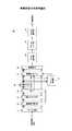
図8は、MIMO伝送を行う場合の、送受信部の構成の一例を示す。この例では、送信アンテナの数をn、受信アンテナの数をmとし、アンテナの数に応じた数の送信部10−1〜10−n、および受信部30−1〜30−mを設ける。 FIG. 8 shows an example of the configuration of the transmission / reception unit when performing MIMO transmission. In this example, the number of transmission antennas is n, the number of reception antennas is m, and the number of transmission units 10-1 to 10-n and reception units 30-1 to 30-m according to the number of antennas are provided.
送信データ系列は、S/P変換部22において,送信アンテナの数に応じてシリアル/パラレル変換されて、それぞれ送信部10−1〜10−nのいずれかに供給される。各送信部において、図6と同様の処理を行い、送信アンテナごとの送信系列を生成する。その際のパイロット系列は、アンテナ間で直交する系列を用いる。 The transmission data series is serial / parallel converted in accordance with the number of transmission antennas in the S / P converter 22 and supplied to one of the transmitters 10-1 to 10-n. Each transmission unit performs the same processing as in FIG. 6 to generate a transmission sequence for each transmission antenna. As a pilot sequence at that time, a sequence orthogonal between antennas is used.
受信部では、複数の受信アンテナで受信された受信信号系列が、それぞれ対応する受信部30−1〜30−mに供給される。各受信部30のチャネル推定部では、IOTA逆フィルタリングによって取り出された直交パイロット系列を用いて、各送信アンテナ−受信アンテナ間のチャネル変動値を求める。 In the reception unit, reception signal sequences received by the plurality of reception antennas are respectively supplied to the corresponding reception units 30-1 to 30-m. The channel estimation unit of each reception unit 30 obtains a channel fluctuation value between each transmission antenna and reception antenna using the orthogonal pilot sequence extracted by IOTA inverse filtering.
同様にして、折り返し処理とIOTA逆フィルタリングにより取り出され、オフセットが除去された復調データ系列に対して、パイロット系列のチャネル推定値に基づいて歪み補償を行う。その後、信号分離部45で個々の情報を分離、検出し、それぞれデータ復調、デインタリーブ、チャネル復号処理を行うことにより、送信信号系列を再生する。 Similarly, distortion compensation is performed based on the channel estimation value of the pilot sequence for the demodulated data sequence extracted by the aliasing process and IOTA inverse filtering and from which the offset is removed. Thereafter, individual information is separated and detected by the signal separation unit 45, and the data demodulation, deinterleaving, and channel decoding processes are performed to reproduce the transmission signal sequence.
このような構成により、隣接するOFDMシンボルおよび/またはサブキャリアからの漏れ込みによる干渉を低減して、チャネル推定を容易にすることができる。 With such a configuration, it is possible to reduce channel interference by reducing interference due to leakage from adjacent OFDM symbols and / or subcarriers.
10 送信部
11 チャネル符号化部
12 インタリーバ
13 データ変調部
14 スイッチ
15 S/P変換部
16 オフセット部
17 IFFT部
18 IOTAフィルタ部
19 送信バッファ
20 折り返し処理部
30 受信部
31 受信バッファ
32 折り返し処理部
33 IOTAフィルタ部
34 FFT部
35 チャネル推定部
36 オフセット除去部
37 チャネル補償部
38 P/S変換部
39 データ復調部
40 デインタリーバ
41 チャネル復号部
45 信号分離部DESCRIPTION OF
Claims (11)
Translated fromJapanese前記パイロットシンボル系列とデータシンボル系列の各々に対して、オフセットQAMとIOTA(Isotropic Orthogonal Transform Algorithm)フィルタ処理を行い、
前記パイロットシンボル系列と前記データシンボル系列の各々について、後続するシンボル領域に影響する部分のIOTAフィルタ出力成分を切り取って、当該IOTAフィルタ出力の先頭部分に加算する折り返し処理を行う、
ことを特徴とする信号伝送方法。Separating a pilot symbol sequence and a data symbol sequence to be transmitted from each other in at least one of a time domain and a frequency domain;
An offset QAM and IOTA (Isotropic Orthogonal Transform Algorithm) filter processing is performed on each of the pilot symbol sequence and the data symbol sequence,
For each of the pilot symbol series and the data symbol series, a part of the IOTA filter output component that affects the subsequent symbol area is cut out and added to the head part of the IOTA filter output.
A signal transmission method characterized by the above.
前記折り返し処理において、前記パイロットシンボル系列のIOTAフィルタ出力波形のうち、nTを越える部分、すなわち最後の(n−1)Tサンプル分を切り取って、このIOTAフィルタ出力波形の先頭部分に加算して、nTサンプル長の送信信号系列を生成する、
ことを特徴とする請求項1に記載の信号伝送方法。When the number of symbols of the pilot symbol sequence is n, the number of samples of the IOTA filter per symbol is nT, and the number of samples of the IOTA filter output waveform of the pilot symbol sequence of n symbols is (2n−1) T. And
In the loopback process, a portion exceeding nT, that is, the last (n−1) T samples of the IOTA filter output waveform of the pilot symbol series is cut out and added to the head portion of the IOTA filter output waveform. generating a transmission signal sequence of nT sample length,
The signal transmission method according to claim 1.
をさらに含むことを特徴とする請求項1に記載の信号伝送方法。The pilot symbol transmission sequence subjected to the IOTA filter processing and the data symbol transmission sequence are transmitted by time division multiplexing and / or frequency division multiplexing,
The signal transmission method according to claim 1, further comprising:
前記受信した送信信号系列の先頭部分を、当該送信信号系列の後ろにコピーする受信側折り返し処理を行い、
前記受信側折り返し処理をした信号系列から送信シンボル系列を取り出す、
工程をさらに含むことを特徴とする請求項1に記載の信号伝送方法。Receiving the transmission signal sequence;
Performing reception side folding processing for copying the head part of the received transmission signal sequence to the back of the transmission signal sequence,
A transmission symbol sequence is extracted from the signal sequence that has undergone the reception-side return processing.
The signal transmission method according to claim 1, further comprising a step.
前記受信した送信信号系列の先頭の(n−1)Tサンプル分を、当該送信信号系列の後ろにコピーして(2n−1)Tサンプルの送信信号系列を再生し、
前記(2n−1)Tサンプルの送信信号系列から、nシンボルのシンボル系列を取り出す、
工程をさらに含むことを特徴とする請求項2に記載の信号伝送方法。Receiving a transmission signal sequence of the nT sample length;
The first (n-1) T samples of the received transmission signal sequence are copied behind the transmission signal sequence to reproduce the (2n-1) T sample transmission signal sequence,
Taking out a symbol sequence of n symbols from the transmission signal sequence of (2n-1) T samples,
The signal transmission method according to claim 2, further comprising a step.
前記OQAM変調されたパイロットシンボル系列およびデータシンボル系列の各々に対してIOTAフィルタ処理を行うIOTAフィルタ部と、
前記IOTAフィルタ処理されたパイロットシンボル系列およびデータシンボル系列の各々に対して、前記IOTAフィルタ出力波形のうち、後続するシンボル領域に影響する部分を切り取って、当該IOTAフィルタ出力波形の先頭部分に加算して送信信号系列を生成する折り返し処理部と、
を備えることを特徴とする送信機。A pilot symbol sequence to be transmitted, an offset unit for performing OQAM modulation on each of the data symbol sequences,
An IOTA filter unit that performs an IOTA filter process on each of the OQAM modulated pilot symbol sequence and data symbol sequence;
For each of the IOTA filtered pilot symbol series and data symbol series, a portion of the IOTA filter output waveform that affects the subsequent symbol area is cut out and added to the head portion of the IOTA filter output waveform. A loopback processing unit for generating a transmission signal sequence,
A transmitter comprising:
前記折り返し処理部は、サンプル数が(2n−1)TのIOTAフィルタ出力波形のうち、nTサンプルを越える部分、すなわち最後の(n−1)Tサンプル分を切り取って、このIOTAフィルタ出力波形の先頭に加算して、nTサンプル長の送信信号系列を生成する、
ことを特徴とする請求項6に記載の送信機。When the number of symbols of the pilot symbol sequence to be transmitted is n, the number of samples of the IOTA filter unit per symbol is nT, and the number of samples of the output waveform of the IOTA filter unit with respect to the pilot symbol sequence of n symbols is ( 2n-1) T,
The aliasing processing unit cuts out the portion exceeding nT samples, that is, the last (n−1) T samples from the IOTA filter output waveform with the number of samples of (2n−1) T, Add to the head to generate a transmission signal sequence of nT sample length,
The transmitter according to claim 6.
前記受信されたパイロット信号系列のうち、先頭部分の受信信号成分を、当該受信パイロット信号系列の後ろにコピーして受信側折り返し処理を行う折り返し処理部と、
前記折り返し処理をした受信パイロット信号系列から、送信パイロットシンボル系列を取り出す受信側IOTAフィルタ部と、
前記IOTAフィルタ部の出力に基づいてチャネル推定を行うチャネル推定部と、
を備えることを特徴とする受信機。A reception buffer for accumulating a pilot signal sequence transmitted over a radio channel;
Of the received pilot signal series, a received signal component at the beginning is copied to the back of the received pilot signal series to perform a reception side loop processing unit,
A receiving-side IOTA filter unit that extracts a transmission pilot symbol sequence from the received pilot signal sequence subjected to the loopback processing;
A channel estimation unit that performs channel estimation based on the output of the IOTA filter unit;
A receiver comprising:
前記IOTAフィルタ部は、前記(n−1)Tサンプルの送信信号系列から、nシンボルのパイロットシンボル系列を取り出す、
ことを特徴とする請求項8に記載の受信機。When the pilot signal sequence having an nT sample length is accumulated in the reception buffer, the loopback processing unit copies the first (n−1) T samples of the pilot signal sequence to the back of the pilot signal sequence. (2n-1) T sample transmission signal sequence is reproduced,
The IOTA filter unit extracts an n-symbol pilot symbol sequence from the (n-1) T-sample transmission signal sequence,
The receiver according to claim 8.
をさらに有することを特徴とする請求項8または9に記載の受信機。An offset removal unit for QAM demodulation by removing the offset of the I component and the Q component from the output of the IOTA filter unit;
The receiver according to claim 8, further comprising:
前記折り返し処理部と、前記IOTAフィルタ部は、前記受信されたデータ信号系列に対して、それぞれ前記折り返し処理と、前記受信側IOTAフィルタ処理を施し、
前記チャネル推定部の推定結果に基づいて、前記IOTA逆フィルタ処理された前記データ信号系列に対するチャネル補償を行うチャネル補償部、
をさらに有することを特徴とする請求項8または9に記載の受信機。The reception buffer accumulates a data signal sequence transmitted on the second radio channel,
The loopback processing unit and the IOTA filter unit perform the loopback processing and the reception-side IOTA filter processing on the received data signal sequence, respectively.
A channel compensation unit for performing channel compensation on the data signal sequence subjected to the IOTA inverse filter processing based on an estimation result of the channel estimation unit;
The receiver according to claim 8, further comprising:
Priority Applications (1)
| Application Number | Priority Date | Filing Date | Title |
|---|---|---|---|
| JP2007056443AJP4838177B2 (en) | 2007-03-06 | 2007-03-06 | Signal transmission method, transmitter and receiver |
Applications Claiming Priority (1)
| Application Number | Priority Date | Filing Date | Title |
|---|---|---|---|
| JP2007056443AJP4838177B2 (en) | 2007-03-06 | 2007-03-06 | Signal transmission method, transmitter and receiver |
Publications (2)
| Publication Number | Publication Date |
|---|---|
| JP2008219671Atrue JP2008219671A (en) | 2008-09-18 |
| JP4838177B2 JP4838177B2 (en) | 2011-12-14 |
Family
ID=39839143
Family Applications (1)
| Application Number | Title | Priority Date | Filing Date |
|---|---|---|---|
| JP2007056443AExpired - Fee RelatedJP4838177B2 (en) | 2007-03-06 | 2007-03-06 | Signal transmission method, transmitter and receiver |
Country Status (1)
| Country | Link |
|---|---|
| JP (1) | JP4838177B2 (en) |
Cited By (4)
| Publication number | Priority date | Publication date | Assignee | Title |
|---|---|---|---|---|
| JP2011071855A (en)* | 2009-09-28 | 2011-04-07 | Fujitsu Semiconductor Ltd | Transmitter |
| US9022849B2 (en) | 2010-07-01 | 2015-05-05 | Aristocrat Technologies Australia Pty Limited | Method of gaming, a gaming system, and a game controller |
| WO2018083925A1 (en)* | 2016-11-01 | 2018-05-11 | 日本電気株式会社 | Wireless communication device, method, program, and recording medium |
| WO2018211800A1 (en)* | 2017-05-18 | 2018-11-22 | ソニー株式会社 | Transmission device, receiving device, method and recording medium |
Citations (1)
| Publication number | Priority date | Publication date | Assignee | Title |
|---|---|---|---|---|
| WO2002025883A1 (en)* | 2000-09-20 | 2002-03-28 | France Telecom | Reference symbol multicarrier signal designed for limiting intersymbol interference |
- 2007
- 2007-03-06JPJP2007056443Apatent/JP4838177B2/ennot_activeExpired - Fee Related
Patent Citations (1)
| Publication number | Priority date | Publication date | Assignee | Title |
|---|---|---|---|---|
| WO2002025883A1 (en)* | 2000-09-20 | 2002-03-28 | France Telecom | Reference symbol multicarrier signal designed for limiting intersymbol interference |
Cited By (8)
| Publication number | Priority date | Publication date | Assignee | Title |
|---|---|---|---|---|
| JP2011071855A (en)* | 2009-09-28 | 2011-04-07 | Fujitsu Semiconductor Ltd | Transmitter |
| US9022849B2 (en) | 2010-07-01 | 2015-05-05 | Aristocrat Technologies Australia Pty Limited | Method of gaming, a gaming system, and a game controller |
| WO2018083925A1 (en)* | 2016-11-01 | 2018-05-11 | 日本電気株式会社 | Wireless communication device, method, program, and recording medium |
| JPWO2018083925A1 (en)* | 2016-11-01 | 2019-07-11 | 日本電気株式会社 | Wireless communication apparatus, method, program, and recording medium |
| WO2018211800A1 (en)* | 2017-05-18 | 2018-11-22 | ソニー株式会社 | Transmission device, receiving device, method and recording medium |
| JP2018196029A (en)* | 2017-05-18 | 2018-12-06 | ソニー株式会社 | Transmitter, receiver, method, and recording medium |
| US11212025B2 (en) | 2017-05-18 | 2021-12-28 | Sony Corporation | Transmitting apparatus, receiving apparatus, method, and recording medium |
| JP7039864B2 (en) | 2017-05-18 | 2022-03-23 | ソニーグループ株式会社 | Transmitter, receiver, method and recording medium |
Also Published As
| Publication number | Publication date |
|---|---|
| JP4838177B2 (en) | 2011-12-14 |
Similar Documents
| Publication | Publication Date | Title |
|---|---|---|
| RU2454808C2 (en) | Modulation circuit on several carriers and also transmitting device and receiving device using this circuit | |
| US7082159B2 (en) | Methods and arrangements in a telecommunications system | |
| KR101282817B1 (en) | Efficient multiplexing of reference signal and data in a wireless communication system | |
| JP4413232B2 (en) | Channel evaluator and method for evaluating channel transfer function, and apparatus and method for supplying pilot sequence | |
| US9363126B2 (en) | Method and apparatus for IFDMA receiver architecture | |
| KR100922980B1 (en) | Channel Estimation Apparatus and Method in Orthogonal Frequency Division Multiplexing System Using Multiple Antennas | |
| JP5609886B2 (en) | Channel estimation for control channel in OFDM system | |
| KR20070056480A (en) | Carrier Frequency Synchronization Apparatus and Method in Wireless Communication System of Orthogonal Frequency Multiplexing | |
| Ganesh et al. | Channel estimation analysis in MIMO-OFDM wireless systems | |
| KR20050043297A (en) | Apparatus and method for interference cancellation of ofdm system using multiple antenna | |
| CN103281265A (en) | Pilot sequence structure in MIMO-OFDM/OQAM (Multi-input Multi-output-Orthogonal Frequency Division Multiplexing/Offset Quadrature Amplitude Modulation) system and channel estimation method | |
| JP4388077B2 (en) | Apparatus and method for effective channel estimation and apparatus and method for providing a pilot sequence | |
| JP4838177B2 (en) | Signal transmission method, transmitter and receiver | |
| US8953697B2 (en) | Channel estimation in a wireless communication system | |
| CN101163123B (en) | Method for generating leading frame and device for generating leading frame | |
| KR100964396B1 (en) | Channel Estimation, Equalization Methods and Systems | |
| KR100781044B1 (en) | Channel Estimation System and Method for Wireless Communication System | |
| KR101499250B1 (en) | Apparatus and method for increasing frequency efficiency of orthogonal frequency division multiplexing transmission system | |
| Pasi et al. | Review on OFDM a brief survey | |
| KR100860457B1 (en) | Apparatus, Method and Channel for Estimating Demodulation in Wireless Packet Transmission System | |
| KR101223048B1 (en) | A method for demodulation of symbol of orthogonal frequency division multiplexing and demodulating apparatus thereof | |
| Al-Mahmoud et al. | Performance evaluation of code-spread OFDM | |
| Salih et al. | Modified OFDM model based on sub-sliding window technique | |
| Dash et al. | Channel estimation in multicarrier communication systems | |
| Sarker et al. | Channel estimation using RF signal processor based on OFDM system |
Legal Events
| Date | Code | Title | Description |
|---|---|---|---|
| A621 | Written request for application examination | Free format text:JAPANESE INTERMEDIATE CODE: A621 Effective date:20090914 | |
| A977 | Report on retrieval | Free format text:JAPANESE INTERMEDIATE CODE: A971007 Effective date:20110622 | |
| A131 | Notification of reasons for refusal | Free format text:JAPANESE INTERMEDIATE CODE: A131 Effective date:20110712 | |
| A521 | Written amendment | Free format text:JAPANESE INTERMEDIATE CODE: A523 Effective date:20110906 | |
| TRDD | Decision of grant or rejection written | ||
| A01 | Written decision to grant a patent or to grant a registration (utility model) | Free format text:JAPANESE INTERMEDIATE CODE: A01 Effective date:20110927 | |
| A01 | Written decision to grant a patent or to grant a registration (utility model) | Free format text:JAPANESE INTERMEDIATE CODE: A01 | |
| A61 | First payment of annual fees (during grant procedure) | Free format text:JAPANESE INTERMEDIATE CODE: A61 Effective date:20110929 | |
| FPAY | Renewal fee payment (event date is renewal date of database) | Free format text:PAYMENT UNTIL: 20141007 Year of fee payment:3 | |
| R150 | Certificate of patent or registration of utility model | Free format text:JAPANESE INTERMEDIATE CODE: R150 | |
| R250 | Receipt of annual fees | Free format text:JAPANESE INTERMEDIATE CODE: R250 | |
| R250 | Receipt of annual fees | Free format text:JAPANESE INTERMEDIATE CODE: R250 | |
| R250 | Receipt of annual fees | Free format text:JAPANESE INTERMEDIATE CODE: R250 | |
| R250 | Receipt of annual fees | Free format text:JAPANESE INTERMEDIATE CODE: R250 | |
| LAPS | Cancellation because of no payment of annual fees |