JP2008217216A - Load balancing method and computer system - Google Patents
Load balancing method and computer systemDownload PDFInfo
- Publication number
- JP2008217216A JP2008217216AJP2007051469AJP2007051469AJP2008217216AJP 2008217216 AJP2008217216 AJP 2008217216AJP 2007051469 AJP2007051469 AJP 2007051469AJP 2007051469 AJP2007051469 AJP 2007051469AJP 2008217216 AJP2008217216 AJP 2008217216A
- Authority
- JP
- Japan
- Prior art keywords
- migration
- logical volume
- host computer
- parity group
- cpu
- Prior art date
- Legal status (The legal status is an assumption and is not a legal conclusion. Google has not performed a legal analysis and makes no representation as to the accuracy of the status listed.)
- Pending
Links
Images


Classifications
- G—PHYSICS
- G06—COMPUTING OR CALCULATING; COUNTING
- G06F—ELECTRIC DIGITAL DATA PROCESSING
- G06F3/00—Input arrangements for transferring data to be processed into a form capable of being handled by the computer; Output arrangements for transferring data from processing unit to output unit, e.g. interface arrangements
- G06F3/06—Digital input from, or digital output to, record carriers, e.g. RAID, emulated record carriers or networked record carriers
- G06F3/0601—Interfaces specially adapted for storage systems
- G06F3/0628—Interfaces specially adapted for storage systems making use of a particular technique
- G06F3/0662—Virtualisation aspects
- G06F3/0665—Virtualisation aspects at area level, e.g. provisioning of virtual or logical volumes
- G—PHYSICS
- G06—COMPUTING OR CALCULATING; COUNTING
- G06F—ELECTRIC DIGITAL DATA PROCESSING
- G06F11/00—Error detection; Error correction; Monitoring
- G06F11/30—Monitoring
- G06F11/34—Recording or statistical evaluation of computer activity, e.g. of down time, of input/output operation ; Recording or statistical evaluation of user activity, e.g. usability assessment
- G06F11/3409—Recording or statistical evaluation of computer activity, e.g. of down time, of input/output operation ; Recording or statistical evaluation of user activity, e.g. usability assessment for performance assessment
- G06F11/3433—Recording or statistical evaluation of computer activity, e.g. of down time, of input/output operation ; Recording or statistical evaluation of user activity, e.g. usability assessment for performance assessment for load management
- G—PHYSICS
- G06—COMPUTING OR CALCULATING; COUNTING
- G06F—ELECTRIC DIGITAL DATA PROCESSING
- G06F3/00—Input arrangements for transferring data to be processed into a form capable of being handled by the computer; Output arrangements for transferring data from processing unit to output unit, e.g. interface arrangements
- G06F3/06—Digital input from, or digital output to, record carriers, e.g. RAID, emulated record carriers or networked record carriers
- G06F3/0601—Interfaces specially adapted for storage systems
- G06F3/0602—Interfaces specially adapted for storage systems specifically adapted to achieve a particular effect
- G06F3/061—Improving I/O performance
- G—PHYSICS
- G06—COMPUTING OR CALCULATING; COUNTING
- G06F—ELECTRIC DIGITAL DATA PROCESSING
- G06F3/00—Input arrangements for transferring data to be processed into a form capable of being handled by the computer; Output arrangements for transferring data from processing unit to output unit, e.g. interface arrangements
- G06F3/06—Digital input from, or digital output to, record carriers, e.g. RAID, emulated record carriers or networked record carriers
- G06F3/0601—Interfaces specially adapted for storage systems
- G06F3/0628—Interfaces specially adapted for storage systems making use of a particular technique
- G06F3/0646—Horizontal data movement in storage systems, i.e. moving data in between storage devices or systems
- G06F3/0647—Migration mechanisms
- G—PHYSICS
- G06—COMPUTING OR CALCULATING; COUNTING
- G06F—ELECTRIC DIGITAL DATA PROCESSING
- G06F3/00—Input arrangements for transferring data to be processed into a form capable of being handled by the computer; Output arrangements for transferring data from processing unit to output unit, e.g. interface arrangements
- G06F3/06—Digital input from, or digital output to, record carriers, e.g. RAID, emulated record carriers or networked record carriers
- G06F3/0601—Interfaces specially adapted for storage systems
- G06F3/0628—Interfaces specially adapted for storage systems making use of a particular technique
- G06F3/0653—Monitoring storage devices or systems
- G—PHYSICS
- G06—COMPUTING OR CALCULATING; COUNTING
- G06F—ELECTRIC DIGITAL DATA PROCESSING
- G06F3/00—Input arrangements for transferring data to be processed into a form capable of being handled by the computer; Output arrangements for transferring data from processing unit to output unit, e.g. interface arrangements
- G06F3/06—Digital input from, or digital output to, record carriers, e.g. RAID, emulated record carriers or networked record carriers
- G06F3/0601—Interfaces specially adapted for storage systems
- G06F3/0668—Interfaces specially adapted for storage systems adopting a particular infrastructure
- G06F3/067—Distributed or networked storage systems, e.g. storage area networks [SAN], network attached storage [NAS]
- G—PHYSICS
- G06—COMPUTING OR CALCULATING; COUNTING
- G06F—ELECTRIC DIGITAL DATA PROCESSING
- G06F11/00—Error detection; Error correction; Monitoring
- G06F11/30—Monitoring
- G06F11/34—Recording or statistical evaluation of computer activity, e.g. of down time, of input/output operation ; Recording or statistical evaluation of user activity, e.g. usability assessment
- G06F11/3466—Performance evaluation by tracing or monitoring
- G06F11/3485—Performance evaluation by tracing or monitoring for I/O devices
Landscapes
- Engineering & Computer Science (AREA)
- Theoretical Computer Science (AREA)
- General Engineering & Computer Science (AREA)
- Physics & Mathematics (AREA)
- General Physics & Mathematics (AREA)
- Human Computer Interaction (AREA)
- Computer Hardware Design (AREA)
- Quality & Reliability (AREA)
- Information Retrieval, Db Structures And Fs Structures Therefor (AREA)
Abstract
Translated fromJapaneseDescription
Translated fromJapanese本発明は、ストレージ装置及び管理計算機を備える計算機システムに関し、特に、パリティグループの負荷を分散する技術に関する。 The present invention relates to a computer system including a storage apparatus and a management computer, and more particularly to a technique for distributing the load of a parity group.
近年、ホスト計算機の性能向上及びインターネット回線の速度向上によって、ホスト計算機が扱うデータ量が増加している。それに伴って、データを保存するストレージ装置に対するアクセス量も増加している。 In recent years, the amount of data handled by a host computer is increasing due to the performance improvement of the host computer and the speed of the Internet line. Along with this, the amount of access to storage devices that store data is also increasing.
ストレージ装置に備わる論理ボリュームに対するアクセス量は、偏りが発生することが多い。この場合、パリティグループの負荷にも偏りが発生する。そこで、パリティグループの負荷の偏りを解消するために、論理ボリュームを他のストレージ装置へ移行する技術が知られている。 In many cases, the access amount to the logical volume provided in the storage apparatus is uneven. In this case, the parity group load is also biased. Therefore, a technique for migrating a logical volume to another storage device is known in order to eliminate the load imbalance of the parity group.
また、ストレージ装置に備わる論理ボリュームの利用率が閾値を超過すると、当該論理ボリュームのデータの移行を指示する技術が開示されている(特許文献1参照。)。これによって、パリティグループの負荷を分散できる。
しかし、特許文献1の技術によると、パリティグループの利用率だけを考慮して、データ移行対象の論理ボリュームが決定されてしまう。そのため、移行に長い時間を要する論理ボリュームがデータ移行対象として決定されてしまうことがある。この場合、パリティグループの利用率を正常値に戻すまでに時間がかかってしまうという問題があった。 However, according to the technique disclosed in
本発明は、前述した問題点に鑑みてなされたものであって、パリティグループの利用率を正常値に戻すための時間を短縮する技術を提供することを目的とする。 The present invention has been made in view of the above-described problems, and an object of the present invention is to provide a technique for shortening the time for returning the parity group utilization rate to a normal value.
本発明の代表的な形態は、ホスト計算機に接続される一つ以上のストレージ装置と、前記ホスト計算機及び前記ストレージ装置に接続される管理計算機と、を備える計算機システムにおける負荷分散方法であって、前記ストレージ装置は、前記ホスト計算機に書き込み要求されるデータを記憶する物理ディスクと、前記物理ディスクを制御するディスクコントローラと、を備え、前記ディスクコントローラは、一つ以上の前記物理ディスクを、仮想的な一つのディスクであるパリティグループとして設定し、前記設定されたパリティグループの記憶領域を、一つ以上の論理ボリュームとして前記ホスト計算機に提供し、前記管理計算機は、前記パリティグループの利用率が閾値以上になった場合に、前記論理ボリュームのデータを、当該論理ボリュームを含むパリティグループ以外の前記パリティグループへ移行するために要する時間である論理ボリュームの移行時間を算出し、前記算出された論理ボリュームの移行時間を参照して、前記利用率が閾値以上となったパリティグループに含まれる前記論理ボリュームの中から、データの移行対象となる前記論理ボリュームを選択することを特徴とする。 A representative form of the present invention is a load balancing method in a computer system comprising one or more storage devices connected to a host computer, and the host computer and a management computer connected to the storage device, The storage device includes a physical disk that stores data requested to be written to the host computer, and a disk controller that controls the physical disk, and the disk controller virtually stores one or more physical disks. A parity group that is a single disk, and the storage area of the set parity group is provided to the host computer as one or more logical volumes, and the management computer has a utilization rate of the parity group as a threshold value. If this happens, the data of the logical volume The logical volume migration time, which is the time required to migrate to the parity group other than the parity group including the volume, is calculated, and the utilization rate is equal to or greater than the threshold with reference to the calculated logical volume migration time. The logical volume as a data transfer target is selected from the logical volumes included in the parity group.
本発明の代表的な形態によれば、パリティグループの利用率を正常値に戻すための時間を短縮できる。 According to the representative embodiment of the present invention, it is possible to shorten the time for returning the parity group utilization rate to a normal value.
以下、本発明の実施の形態を図面を参照して説明する。 Hereinafter, embodiments of the present invention will be described with reference to the drawings.
(第1の実施の形態)
図1は、本発明の第1の実施の形態の計算機システムの構成のブロック図である。(First embodiment)
FIG. 1 is a block diagram showing a configuration of a computer system according to the first embodiment of this invention.
計算機システムは、ホスト計算機1000、管理ホスト計算機1100、FCスイッチ1200、IPスイッチ1300及びストレージ装置1400を備える。 The computer system includes a
ホスト計算機1000、FCスイッチ1200及びIPスイッチ1300は、それぞれ一つずつが図示されているが、計算機システムにいくつ備わっていてもよい。同様に、ストレージ装置1400は、二つが図示されているが、計算機システムにいくつ備わっていてもよい。 One
ホスト計算機1000は、ストレージ装置1400に対してデータの読み書きを要求する。また、ホスト計算機1000は、FCI/F1001、CPU1002、入力装置1003、出力装置1004、IPI/F1005、記憶装置1006及びメモリ1007を備える。 The
FCI/F1001は、FCスイッチ1200を介してストレージ装置1400に接続されるインタフェースである。IPI/F1005は、IPスイッチ1300を介して管理ホスト計算機1100に接続されるインタフェースである。 The FC I / F 1001 is an interface connected to the
CPU1002は、メモリ1007に記憶されるプログラムを実行することによって、各種処理を行う。メモリ1007は、CPU1002によって実行されるプログラム及びCPU1002によって必要とされる情報などを記憶する。なお、メモリ1007については、図2で詳細を説明する。 The
記憶装置1006は、プログラムなどを含む各種情報を記憶する。入力装置1003には、各種情報が入力される。入力装置1003は、例えば、キーボード又はマウスである。出力装置1004は、各種情報を出力する。出力装置1004は、例えば、ディスプレイである。 The
管理ホスト計算機1100は、当該計算機システムの全体を管理する。また、管理ホスト計算機1100は、FCI/F1101、CPU1102、入力装置1103、出力装置1104、IPI/F1105、記憶装置1106及びメモリ1107を備える。 The
FCI/F1101は、FCスイッチ1200を介してストレージ装置1400に接続されるインタフェースである。IPI/F1105は、IPスイッチ1300を介してホスト計算機1000に接続されるインタフェースである。 The FC I / F 1101 is an interface connected to the
CPU1102は、メモリ1107に記憶されるプログラムを実行することによって、各種処理を行う。メモリ1107は、CPU1102によって実行されるプログラム及びCPU1102によって必要とされる情報などを記憶する。なお、メモリ1107については、図3で詳細を説明する。 The
記憶装置1106は、プログラムなどを含む各種情報を記憶する。入力装置1103には、各種情報が入力される。入力装置1103は、例えば、キーボード又はマウスである。出力装置1104は、各種情報を出力する。出力装置1104は、例えば、ディスプレイである。 The
FCスイッチ1200は、ホスト計算機1000とストレージ装置1400との間で送受信されるデータ、ストレージ装置1400間で送受信されるデータ、及び管理ホスト計算機1100とストレージ装置1400との間で送受信されるデータを転送する。例えば、FCスイッチ1200は、書込要求、書込データ、読出要求又は読出データなどを転送する。 The
FCスイッチ1200は、CPU1201、メモリ1202、IPI/F1203及びFCI/F1205を備える。 The
IPI/F1203は、LAN(Local Area Network)などを介して管理ホスト計算機1100に接続されるインタフェースである。FCI/F1205は、FC(Fibre Channel)を介してホスト計算機1000、管理ホスト計算機1100又はストレージ装置1400に接続されるインタフェースである。 The IPI / F 1203 is an interface connected to the
CPU1201は、メモリ1202に記憶されるプログラムを実行することによって、各種処理を行う。例えば、CPU1201は、FCスイッチ1200の処理の全体を制御する。 The
メモリ1202は、CPU1201によって実行されるプログラム及びCPU1201によって必要とされる情報などを記憶する。例えば、メモリ1202は、ルーティングテーブル及びルーティングプログラムを記憶する。ルーティングプログラムは、ルーティングテーブルに基づいて、受信したデータを転送する。 The
IPスイッチ1300は、ホスト計算機1000と管理ホスト計算機1100との間で送受信されるデータ及び管理ホスト計算機1100とストレージ装置1400との間で送受信されるデータを転送する。例えば、IPスイッチ1300は、管理情報を転送する。 The
IPスイッチ1300は、CPU1301、メモリ1302及びIPI/F1303を備える。 The
IPI/F1303は、LANなどを介してホスト計算機1000、管理ホスト計算機1100又はストレージ装置1400に接続されるインタフェースである。 The IP I / F 1303 is an interface connected to the
CPU1301は、メモリ1302に記憶されるプログラムを実行することによって、各種処理を行う。例えば、CPU1301は、IPスイッチ1300の処理の全体を制御する。 The
メモリ1302は、CPU1301によって実行されるプログラム及びCPU1301によって必要とされる情報などを記憶する。例えば、メモリ1302は、ルーティングテーブル及びルーティングプログラムを記憶する。ルーティングプログラムは、ルーティングテーブルに基づいて、受信したデータを転送する。 The
ストレージ装置1400は、FCI/F1401、IPI/F1402、CPU1403、メモリ1404、ディスクコントローラ1405及びディスクドライブ1406を備える。 The
FCI/F1401は、FCスイッチ1200を介してホスト計算機1000、管理ホスト計算機1100又は他のストレージ装置1400に接続されるインタフェースである。IPI/F1402は、IPスイッチ1300を介して管理ホスト計算機1100に接続されるインタフェースである。 The FC I /
CPU1403は、メモリ1404に記憶されるプログラムを実行することによって、各種処理を行う。例えば、CPU1403は、当該ストレージ装置1400の処理の全体を制御する。 The
メモリ1404は、CPU1403によって実行されるプログラム及びCPU1403によって必要とされる情報などを記憶する。なお、メモリ1404については、図4で詳細を説明する。 The
ディスクドライブ1406は、ホスト計算機1000から書き込みを要求されたデータを記憶する。ディスクコントローラ1405は、ディスクドライブ1406へのデータの入出力を制御する。 The
なお、ディスクコントローラ1405は、ディスクドライブ1406を冗長性のあるRAID(Redundant Array of Independent Disks)構成とする。そして、ディスクコントローラ1405は、一つ以上のディスクドライブ1406の集合を仮想的なディスク(パリティグループ1410)として扱う。 The
更に、ディスクコントローラ1405は、パリティグループ1410を一つ以上の論理ボリューム(LU)1411に分けて、ホスト計算機1000及び管理ホスト計算機1100に提供する。これによって、ホスト計算機1000及び管理ホスト計算機1100は、ストレージ装置1400に備わるディスクドライブ1406の記憶領域を、LU1411として認識する。 Further, the
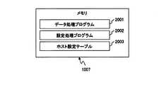
図2は、本発明の第1の実施の形態のホスト計算機1000に備わるメモリ1007の構成のブロック図である。 FIG. 2 is a block diagram showing a configuration of the
ホスト計算機1000に備わるメモリ1007は、データ処理プログラム2001、設定処理プログラム2002及びホスト設定テーブル2003を記憶する。 A
データ処理プログラム2001は、ストレージ装置1400に対してデータを読み書きする。設定処理プログラム2002は、ホスト設定テーブル2003を作成及び更新する。 The
ホスト設定テーブル2003は、当該ホスト計算機1000の設定に関する情報を示す。なお、ホスト設定テーブル2003については、図5で詳細を説明する。 The host setting table 2003 shows information related to the setting of the
図3は、本発明の第1の実施の形態の管理ホスト計算機1100に備わるメモリ1107の構成のブロック図である。 FIG. 3 is a block diagram showing a configuration of the
管理ホスト計算機1100に備わるメモリ1107は、閾値超過検出プログラム7001、移行対象LU決定プログラム7002、閾値設定テーブル7003及び移行対象候補LUテーブル7004を記憶する。 A
閾値超過検出プログラム7001は、パリティグループ1410の利用率が閾値以上であるか否かを判定する。なお、閾値超過検出プログラム7001の処理については、図11で詳細を説明する。 The threshold
移行対象LU決定プログラム7002は、移行対象となるLU1411を決定する。なお、移行対象LU決定プログラム7002の処理については、図12で詳細を説明する。 The migration target
閾値設定テーブル7003は、パリティグループ1410の利用率に関する閾値を示す。なお、閾値設定テーブル7003については、図6で詳細を説明する。 The threshold setting table 7003 shows thresholds related to the utilization rate of the
移行対象候補LUテーブル7004は、移行対象となるLU1411の候補に関する情報を示す。なお、移行対象候補LUテーブル7004については、図7で詳細を説明する。 The migration target candidate LU table 7004 shows information related to
図4は、本発明の第1の実施の形態のストレージ装置1400に備わるメモリ1404の構成のブロック図である。 FIG. 4 is a block diagram showing a configuration of the
ストレージ装置1400に備わるメモリ1404は、データ処理プログラム5001、データ移行プログラム5002、設定処理プログラム5003、ストレージ装置設定テーブル5004及びストレージ装置稼動情報テーブル5005を記憶する。 A
データ処理プログラム5001は、ホスト計算機1000から読出要求を受信すると、読み出しを要求されたデータをLU1411から読み出す。そして、データ処理プログラム5001は、読み出したデータを、ホスト計算機1000に送信する。また、データ処理プログラム5001は、ホスト計算機1000から書込要求を受信すると、書き込みを要求されたデータをLU1411に書き込む。 When the
データ移行プログラム5002は、LU1411のデータを、当該LU1411が属するパリティグループ14101以外のパリティグループ1410(移行先のパリティグループ1410)に移行する。なお、本実施の形態では、移行先のパリティグループ1410が予め設定されている。また、移行先のパリティグループ1410と、移行対象のLU1411が属するパリティグループ1410(移行元のパリティグループ1410)とは、同一のストレージ装置1400に構成されていてもよいし、異なるストレージ装置1400に構成されていてもよい。 The
設定処理プログラム5003は、ストレージ装置設定テーブル5004を作成及び更新する。 The setting
ストレージ装置設定テーブル5004は、ストレージ装置1400の設定に関する情報を示す。なお、ストレージ装置設定テーブル5004については、図8で詳細を説明する。 The storage device setting table 5004 shows information related to the settings of the
ストレージ装置稼動情報テーブル5005は、現時点におけるストレージ装置1400の性能に関する情報を示す。なお、ストレージ装置稼動情報テーブル5005については、図9で詳細を説明する。 The storage device operation information table 5005 shows information related to the performance of the
図5は、本発明の第1の実施の形態のホスト計算機1000に備わるメモリ1007に記憶されるホスト設定テーブル2003の構成図である。 FIG. 5 is a configuration diagram of the host setting table 2003 stored in the
ホスト設定テーブル2003は、ホスト名8001、使用LUN8002及び接続先IF名8003を含む。 The host setting table 2003 includes a
ホスト名8001は、ホスト計算機1000の一意な識別子である。使用LUN8002は、当該レコードのホスト名8001によって識別されるホスト計算機1000がアクセス可能なLU1411の一意な識別子である。 The
接続先IF名8003は、当該レコードのホスト名8001によって識別されるホスト計算機1000が、当該レコードの使用LUN8002によって識別されるLU1411にアクセスする時に使用されるFCI/F1401の一意な識別子である。 The connection destination IF
図6は、本発明の第1の実施の形態の管理ホスト計算機1100に備わるメモリ1107に記憶される閾値設定テーブル7003の構成図である。 FIG. 6 is a configuration diagram of the threshold setting table 7003 stored in the
閾値設定テーブル7003は、ストレージ名15001、PG名15002、PG利用率閾値15003及び閾値超過フラグ15004を含む。 The threshold setting table 7003 includes a
ストレージ名15001は、ストレージ装置1400の一意な識別子である。PG名15002は、当該レコードのストレージ名15001によって識別されるストレージ装置1400において構成されるパリティグループ1410の一意な識別子である。 The
PG利用率閾値15003は、当該レコードのPG名15002によって識別されるパリティグループ1410の利用率に関する閾値である。 The PG
閾値超過フラグ15004は、当該レコードのPG名15002によって識別されるパリティグループ1410の利用率が、当該レコードのPG利用率閾値15003以上であるか否かを示す。本実施の形態では、当該レコードのPG名15002によって識別されるパリティグループ1410の利用率が、当該レコードのPG利用率閾値15003以上である場合、閾値超過フラグ15004には「ON」が格納される。一方、当該レコードのPG名15002によって識別されるパリティグループ1410の利用率が、当該レコードのPG利用率閾値15003未満である場合、閾値超過フラグ15004には「OFF」が格納される。 The threshold
図7は、本発明の第1の実施の形態の管理ホスト計算機1100に備わるメモリ1107に記憶される移行対象候補LUテーブル7004の構成図である。 FIG. 7 is a configuration diagram of the migration target candidate LU table 7004 stored in the
移行対象候補LUテーブル7004は、移行対象候補LUN16001、オンライン移行時間16002、移行後PG利用率16003、移行後性能評価16004及び移行フラグ16005を含む。 The migration target candidate LU table 7004 includes a migration
移行対象候補LUN16001は、移行対象となるLU1411の候補の一意な識別子である。移行対象候補LUN16001には、一つのLU1411の識別子が格納されてもよいし、複数のLU1411の識別子が格納されてもよい。移行対象候補LUN16001に複数のLU1411の識別子が格納されている場合、当該複数のLU1411のすべてのデータを移行することを示す。 The migration
オンライン移行時間16002は、当該レコードの移行対象候補LUN16001によって識別されるLU1411のデータをオンラインで移行するために必要な時間である。 The
オンラインでのデータ移行とは、ホスト計算機1000から当該LU1411へのアクセスを継続した状態におけるデータ移行である。一方、オフラインでのデータ移行とは、ホスト計算機1000から当該LU1411へのアクセスを停止した状態におけるデータ移行である。 Online data migration is data migration in a state where access from the
移行後PG利用率16003は、当該レコードの移行対象候補LUN16001によって識別されるLU1411のデータを移行した後における、移行元のパリティグループ1410の利用率の予測値である。 The post-migration
移行後性能評価16004は、当該レコードの移行後PG利用率16003が、閾値設定テーブル7003のPG利用率閾値15003未満であるか否かを示す。本実施の形態では、当該レコードの移行後PG利用率16003が閾値設定テーブル7003のPG利用率閾値15003未満の場合、移行後性能評価16004には「OK」が格納される。一方、当該レコードの移行後PG利用率16003が閾値設定テーブル7003のPG利用率閾値15003以上の場合、移行後性能評価16004には「NG」が格納される。 The
移行フラグ16005は、当該レコードの移行対象候補LUN16001によって識別されるLU1411を移行対象とするか否かを示す。本実施の形態では、当該レコードの移行対象候補LUN16001によって識別されるLU1411が移行対象となった場合、移行フラグ16005には「ON」が格納される。一方、当該レコードの移行対象候補LUN16001によって識別されるLU1411が移行対象とならなかった場合、移行フラグ16005には「OFF」が格納される。 The
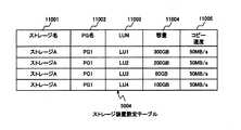
図8は、本発明の第1の実施の形態のストレージ装置1400に備わるメモリ1404に記憶されるストレージ装置設定テーブル5004の構成図である。 FIG. 8 is a configuration diagram of the storage device setting table 5004 stored in the
ストレージ装置設定テーブル5004は、ストレージ名11001、PG名11002、LUN11003、容量11004及びコピー速度11005を含む。 The storage device setting table 5004 includes a
ストレージ名11001は、ストレージ装置1400の一意な識別子である。PG名11002は、当該レコードのストレージ名11001によって識別されるストレージ装置1400において構成されるパリティグループ1410の一意な識別子である。LUN11003は、当該レコードのPG名11002によって識別されるパリティグループ1410に属するLU1411の一意な識別子である。 The
容量11004は、当該レコードのLUN11003によって識別されるLU1411の容量である。コピー速度11005は、当該レコードのLUN11003によって識別されるLU1411のデータを、当該LU1411が属するパリティグループ14101以外のパリティグループ1410に移行する時における単位時間当たりのコピーデータ量である。 The
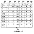
図9は、本発明の第1の実施の形態のストレージ装置1400に備わるメモリ1404に記憶されるストレージ装置稼動情報テーブル5005の構成図である。 FIG. 9 is a configuration diagram of the storage device operation information table 5005 stored in the
ストレージ装置稼動情報テーブル5005は、ストレージ名13001、PG名13002、PG利用率13003、LUN13004、LU利用率13005及び書込ペース13006を含む。 The storage device operation information table 5005 includes a
ストレージ名13001は、ストレージ装置1400の一意な識別子である。PG名13002は、当該レコードのストレージ名13001によって識別されるストレージ装置1400において構成されるパリティグループ1410の一意な識別子である。 The
PG利用率13003は、当該レコードのPG名13002によって識別されるパリティグループ1410の利用率である。なお、パリティグループ1410の利用率は、所定の時間に対する、当該所定の時間のうち当該パリティグループ1410に対するアクセスによってディスクドライブ1406が稼動している時間の割り合いを示す。 The
LUN13004は、当該レコードのPG名13002によって識別されるパリティグループ1410に属するLU1411の一意な識別子である。 The
LU利用率13005は、当該レコードのLUN13004によって識別されるLU1411の利用率である。なお、LU1411の利用率は、所定の時間に対する、当該所定の時間のうち当該LU1411に対するアクセスによってディスクドライブ1406が稼動している時間の割り合いを示す。そのため、パリティグループ1410の利用率は、当該パリティグループ1410に属するすべてのLU1411の利用率の合計となる。 The
書込ペース13006は、当該レコードのLUN13004によって識別されるLU1411に対する単位時間当たりの書込データ量である。 The
図10は、本発明の第1の実施の形態の計算機システムの性能チューニング処理のシーケンス図である。 FIG. 10 is a sequence diagram of performance tuning processing of the computer system according to the first embodiment of this invention.
本シーケンス図では、パリティグループ1410の利用率が閾値を超えている場合を説明する。 This sequence diagram describes a case where the utilization rate of the
ストレージ装置1400に備わるCPU1403は、所定のタイミングで当該ストレージ装置1400の稼動情報を計測する。なお、稼動情報は、パリティグループ1410の利用率、LU1411の利用率及びLU1411への書込ペースを含む。そして、ストレージ装置1400に備わるCPU1403は、計測した稼動情報を、ストレージ装置稼動情報テーブル5005に格納する。 The
次に、ストレージ装置1400に備わるCPU1403は、ストレージ装置設定テーブル5004及びストレージ装置稼動情報テーブル5005を管理ホスト計算機1100に送信する(17001)。 Next, the
管理ホスト計算機1100に備わるCPU1102は、ストレージ装置設定テーブル5004及びストレージ装置稼動情報テーブル5005をストレージ装置1400から受信する。次に、管理ホスト計算機1100に備わるCPU1102は、閾値超過検出処理を実行する(17002)。なお、閾値超過検出処理については、図11で詳細を説明する。 The
次に、管理ホスト計算機1100に備わるCPU1102は、移行対象LU決定処理を実行する(17003)。なお、移行対象LU決定処理については、図12で詳細を説明する。 Next, the
次に、管理ホスト計算機1100に備わるCPU1102は、移行対象候補LUテーブル7004の移行フラグ16005に「ON」が格納されているレコードを、移行対象候補LUテーブル7004から選択する。次に、管理ホスト計算機1100に備わるCPU1102は、選択したレコードから、移行対象候補LUN16001を抽出する。 Next, the
次に、管理ホスト計算機1100に備わるCPU1102は、LU移行要求をストレージ装置1400に送信する(17004)。なお、当該LU移行要求では、抽出された移行対象候補LUN16001によって識別されるLU1411の移行が要求される。 Next, the
ストレージ装置1400に備わるCPU1403は、LU移行要求を管理ホスト計算機1100から受信する。すると、ストレージ装置1400に備わるCPU1403は、移行対象のLU1411のデータを、当該LU1411が属するパリティグループ1410以外のパリティグループ1410に移行する(17005)。これによって、移行先のパリティグループ1410には、新たなLU1411(移行先のLU1411)が作成される。 The
ストレージ装置1400に備わるCPU1403は、LU1411のデータの移行が完了すると、ストレージ装置設定テーブル5004及びストレージ装置稼動情報テーブル5005を更新する。 When the data migration of the
具体的には、ストレージ装置1400に備わるCPU1403は、移行対象のLU1411の識別子とストレージ装置設定テーブル5004のLUN11003とが一致するレコードを、ストレージ装置設定テーブル5004から削除する。次に、ストレージ装置1400に備わるCPU1403は、移行対象のLU1411の識別子とストレージ装置稼動情報テーブル5005のLUN13004とが一致するレコードを、ストレージ装置稼動情報テーブル5005から削除する。 Specifically, the
更に、ストレージ装置1400に備わるCPU1403は、移行対象のLU1411へアクセス可能なホスト計算機1000にパスの切り替えを指示する。ホスト計算機1000に備わるCPU1002は、パスの切り替えの指示を受けると、ホスト設定テーブル2003を更新する。 Further, the
一方、移行先のLU1411を提供するストレージ装置1400(移行先のストレージ装置1400)に備わるCPU1403も、ストレージ装置設定テーブル5004及びストレージ装置稼動情報テーブル5005を更新する。 On the other hand, the
具体的には、移行先のストレージ装置1400に備わるCPU1403は、ストレージ装置設定テーブル5004及びストレージ装置稼動情報テーブル5005に、新たなレコードを作成する。次に、移行先のストレージ装置1400に備わるCPU1403は、作成した新たなレコードに、作成された移行先のLU1411に関する情報を格納する。 Specifically, the
以上のように、当該計算機システムは、性能チューニング処理を終了する。 As described above, the computer system ends the performance tuning process.
図11は、本発明の第1の実施の形態の管理ホスト計算機1100によって実行される閾値超過検出処理のフローチャートである。 FIG. 11 is a flowchart of the threshold excess detection process executed by the
閾値超過検出処理は、性能チューニング処理(図10)のステップ17002において実行される。 The threshold excess detection process is executed in
まず、管理ホスト計算機1100に備わるCPU1102は、閾値設定テーブル7003のレコードを、上から順番に一つずつ選択する(18001)。 First, the
次に、管理ホスト計算機1100に備わるCPU1102は選択したレコードから、ストレージ名15001、PG名15002及びPG利用率閾値15003を抽出する。 Next, the
次に、管理ホスト計算機1100に備わるCPU1102は、抽出したストレージ名15001とストレージ装置稼動情報テーブル5005のストレージ名13001とが一致するレコードを、性能チューニング処理のステップ17001で受信したストレージ装置稼動情報テーブル5005から選択する。次に、管理ホスト計算機1100に備わるCPU1102は、抽出したPG名15002とストレージ装置稼動情報テーブル5005のPG名13002とが一致するレコードを、選択したレコードの中から選択する。 Next, the
次に、管理ホスト計算機1100に備わるCPU1102は、選択したレコードから、PG利用率13003を抽出する。次に、管理ホスト計算機1100に備わるCPU1102は、抽出したPG利用率13003が、抽出したPG利用率閾値15003以上であるか否かを判定する(18002)。 Next, the
PG利用率13003がPG利用率閾値15003未満の場合、管理ホスト計算機1100に備わるCPU1102は、閾値設定テーブル7003から選択したレコードの閾値超過フラグ15004に「OFF」を格納する。 When the
一方、PG利用率13003がPG利用率閾値15003以上の場合、管理ホスト計算機1100に備わるCPU1102は、閾値設定テーブル7003から選択したレコードの閾値超過フラグ15004に「ON」を格納する(18003)。 On the other hand, when the
次に、管理ホスト計算機1100に備わるCPU1102は、ステップ18001において、閾値設定テーブル7003に含まれるすべてのレコードを選択したか否かを判定する(18004)。 Next, the
閾値設定テーブル7003に含まれるいずれかのレコードを選択していない場合、管理ホスト計算機1100に備わるCPU1102は、ステップ18001に戻る。そして、管理ホスト計算機1100に備わるCPU1102は、次のレコードを閾値設定テーブル7003から選択し、ステップ18002に進む。 If any record included in the threshold setting table 7003 is not selected, the
一方、閾値設定テーブル7003に含まれるすべてのレコードを選択した場合、管理ホスト計算機1100に備わるCPU1102は、当該閾値超過検出処理を終了する。 On the other hand, when all the records included in the threshold setting table 7003 are selected, the
図12は、本発明の第1の実施の形態の管理ホスト計算機1100によって実行される移行対象LU決定処理のフローチャートである。 FIG. 12 is a flow chart for migration target LU determination processing executed by the
移行対象LU決定処理は、性能チューニング処理(図10)のステップ17003において実行される。 The migration target LU determination process is executed in
まず、管理ホスト計算機1100に備わるCPU1102は、閾値超過フラグ15004に「ON」が格納されているレコードを、閾値設定テーブル7003から選択する。次に、管理ホスト計算機1100に備わるCPU1102は、選択したレコードから、ストレージ名15001及びPG名15002を抽出する。 First, the
次に、管理ホスト計算機1100に備わるCPU1102は、抽出したストレージ名15001とストレージ装置設定テーブル5004のストレージ名11001とが一致するレコードを、性能チューニング処理のステップ17001で受信したストレージ装置設定テーブル5004から選択する。次に、管理ホスト計算機1100に備わるCPU1102は、抽出したPG名15002とストレージ装置設定テーブル5004のPG名11002とが一致するレコードを、選択したレコードの中から選択する。 Next, the
次に、管理ホスト計算機1100に備わるCPU1102は、選択したすべてのレコードから、LUN11003を抽出する。これによって、管理ホスト計算機1100に備わるCPU1102は、利用率が閾値を越えたパリティグループ1410に属するすべてのLU1411を特定できる。 Next, the
次に、管理ホスト計算機1100に備わるCPU1102は、抽出したLUN11003のすべての組み合わせの数のレコードを、移行対象候補LUテーブル7004に作成する。そして、管理ホスト計算機1100に備わるCPU1102は、抽出したLUN11003の組み合わせのそれぞれを、作成したそれぞれのレコードの移行対象候補LUN16001に格納する(19001)。 Next, the
なお、抽出されたLUN11003が、「LU1」、「LU2」、「LU3」及び「LU4」の場合について説明する。この場合、抽出されたLUN11003のすべての組み合わせは、「LU1」、「LU2」、「LU3」、「LU4」、「LU1及びLU2」、「LU1及びLU3」、「LU1及びLU4」、「LU2及びLU3」、「LU2及びLU4」、「LU3及びLU4」、「LU1、LU2及びLU3」、「LU1、LU2、及びLU4」、「LU1、LU3及びLU4」、「LU2、LU3及びLU4」並びに「LU1、LU2、LU3及びLU4」となる。 The case where the extracted
次に、管理ホスト計算機1100に備わるCPU1102は、移行対象候補LUテーブル7004のレコードを、上から順番に一つずつ選択する(19002)。 Next, the
次に、管理ホスト計算機1100に備わるCPU1102は、移行時間計算処理を実行する(19003)。なお、移行時間計算処理については、図13で詳細を説明する。 Next, the
次に、管理ホスト計算機1100に備わるCPU1102は、移行後性能評価処理を実行する(19004)なお、移行後性能評価処理については、図14で詳細を説明する。 Next, the
次に、管理ホスト計算機1100に備わるCPU1102は、ステップ19002において、移行対象候補LUテーブル7004に含まれるすべてのレコードを選択したか否かを判定する(19005)。 Next, the
移行対象候補LUテーブル7004に含まれるいずれかのレコードを選択していない場合、管理ホスト計算機1100に備わるCPU1102は、ステップ19002に戻る。そして、管理ホスト計算機1100に備わるCPU1102は、次のレコードを移行対象候補LUテーブル7004から選択し、ステップ19003に進む。 If any record included in the migration target candidate LU table 7004 has not been selected, the
一方、閾値設定テーブル7003に含まれるすべてのレコードを選択した場合、管理ホスト計算機1100に備わるCPU1102は、移行対象LU選択処理を実行する(19006)。なお、移行対象LU選択処理については、図15で詳細を説明する。 On the other hand, when all the records included in the threshold setting table 7003 are selected, the
そして、管理ホスト計算機1100に備わるCPU1102は、当該移行対象LU決定処理を終了する。 Then, the
図13は、本発明の第1の実施の形態の管理ホスト計算機1100によって実行される移行時間計算処理のフローチャートである。 FIG. 13 is a flow chart for migration time calculation processing executed by the
移行時間計算処理は、移行対象LU決定処理(図12)のステップ19003において実行される。 The migration time calculation process is executed in
まず、管理ホスト計算機1100に備わるCPU1102は、移行対象LU決定処理のステップ19002で移行対象候補LUテーブル7004から選択したレコードから、移行対象候補LUN16001を抽出する。 First, the
次に、管理ホスト計算機1100に備わるCPU1102は、抽出した移行対象候補LUN16001とストレージ装置設定テーブル5004のLUN11003とが一致するレコードを、性能チューニング処理のステップ17001で受信したストレージ装置設定テーブル5004から選択する。次に、管理ホスト計算機1100に備わるCPU1102は、選択したレコードから容量11004及びコピー速度11005を抽出する。 Next, the
次に、管理ホスト計算機1100に備わるCPU1102は、抽出した容量11004を、抽出したコピー速度11005で割る。これによって、管理ホスト計算機1100に備わるCPU1102は、抽出した移行対象候補LUN16001によって識別されるLU1411のオフライン移行時間を算出する(20001)。 Next, the
次に、管理ホスト計算機1100に備わるCPU1102は、抽出した移行対象候補LUN16001とストレージ装置稼動情報テーブル5005のLUN13004とが一致するレコードを、性能チューニング処理のステップ17001で受信したストレージ装置稼動情報テーブル5005から選択する。次に、管理ホスト計算機1100に備わるCPU1102は、選択したレコードから、書込ペース13006を抽出する。 Next, the
次に、管理ホスト計算機1100に備わるCPU1102は、算出したオフライン移行時間に、抽出した書込ペース13006を乗じる。これによって、管理ホスト計算機1100に備わるCPU1102は、移行中に書き込まれるデータ量を示す差分データ量を算出する(20002)。 Next, the
次に、管理ホスト計算機1100に備わるCPU1102は、算出した差分データ量を、抽出したコピー速度11005で割る。これによって、管理ホスト計算機1100に備わるCPU1102は、差分データの移行に必要な時間を示す差分データ移行時間を算出する(20003)。 Next, the
次に、管理ホスト計算機1100に備わるCPU1102は、算出したオフライン移行時間に、算出した差分データ移行時間を加える。これによって、管理ホスト計算機1100に備わるCPU1102は、オンライン移行時間を算出する。次に、管理ホスト計算機1100に備わるCPU1102は、算出したオンライン移行時間を60で割ることによって、分を単位とするオンライン移行時間を算出する(20004)。 Next, the
次に、管理ホスト計算機1100に備わるCPU1102は、移行対象LU決定処理のステップ19002で移行対象候補LUテーブル7004から選択したレコードのオンライン移行時間16002に、算出したオンライン移行時間を格納する(20005)。 Next, the
そして、管理ホスト計算機1100に備わるCPU1102は、当該移行時間計算処理を終了する。 Then, the
ここで、抽出された移行対象候補LUN16001に、複数のLU1411の識別子が格納されている場合を説明する。つまり、複数のLU1411が移行対象候補となっている場合である。 Here, a case where identifiers of a plurality of
この場合、管理ホスト計算機1100に備わるCPU1102は、移行対象候補に含まれるそれぞれのLU1411のオンライン移行時間を算出する。そして、管理ホスト計算機1100に備わるCPU1102は、算出したオンライン移行時間を合計することによって、移行対象候補となっているすべてのLU1411を移行した場合のオンライン移行時間を算出する。 In this case, the
図14は、本発明の第1の実施の形態の管理ホスト計算機1100によって実行される移行後性能評価処理のフローチャートである。 FIG. 14 is a flow chart for post-migration performance evaluation processing executed by the
移行後性能評価処理は、移行対象LU決定処理(図12)のステップ19004において実行される。 The post-migration performance evaluation process is executed in
まず、管理ホスト計算機1100に備わるCPU1102は、移行対象LU決定処理のステップ19002で移行対象候補LUテーブル7004から選択したレコードから、移行対象候補LUN16001を抽出する。 First, the
次に、管理ホスト計算機1100に備わるCPU1102は、抽出した移行対象候補LUN16001とストレージ装置稼動情報テーブル5005のLUN13004とが一致するレコードを、ストレージ装置稼動情報テーブル5005から選択する。なお、抽出された移行対象候補LUN16001に、複数のLU1411の識別子が格納されている場合、管理ホスト計算機1100に備わるCPU1102は、抽出された移行対象候補LUN16001に含まれるいずれかの識別子とストレージ装置稼動情報テーブル5005のLUN13004とが一致するすべてのレコードを、ストレージ装置稼動情報テーブル5005から選択する。 Next, the
次に、管理ホスト計算機1100に備わるCPU1102は、選択したすべてのレコードから、PG利用率13003及びLU利用率13005を抽出する。次に、管理ホスト計算機1100に備わるCPU1102は、抽出したすべてのLU利用率13005の合計を算出する(21001)。 Next, the
次に、管理ホスト計算機1100に備わるCPU1102は、抽出したPG利用率13003から、算出したLU利用率13005の合計を減算する。これによって、管理ホスト計算機1100に備わるCPU1102は、移行後PG利用率を算出する(21002)。 Next, the
次に、管理ホスト計算機1100に備わるCPU1102は、移行対象LU決定処理のステップ19002で移行対象候補LUテーブル7004から選択したレコードの移行後PG利用率16003に、算出した移行後PG利用率を格納する(21003)。 Next, the
次に、管理ホスト計算機1100に備わるCPU1102は、移行対象LU決定処理のステップ19001で閾値設定テーブル7003から選択したレコードから、PG利用率閾値15003を抽出する。次に、管理ホスト計算機1100に備わるCPU1102は、算出した移行後PG利用率が、抽出したPG利用率閾値15003以上であるか否かを判定する(21004)。 Next, the
移行後PG利用率がPG利用率閾値15003以上の場合、管理ホスト計算機1100に備わるCPU1102は、移行対象LU決定処理のステップ19001で閾値設定テーブル7003から選択したレコードの移行後性能評価16004に、「NG」を格納する(21006)。そして、管理ホスト計算機1100に備わるCPU1102は、当該移行後性能評価処理を終了する。 When the post-migration PG usage rate is equal to or higher than the PG usage
一方、移行後PG利用率がPG利用率閾値15003未満の場合、管理ホスト計算機1100に備わるCPU1102は、移行対象LU決定処理のステップ19001で閾値設定テーブル7003から選択したレコードの移行後性能評価16004に、「OK」を格納する(21005)。そして、管理ホスト計算機1100に備わるCPU1102は、当該移行後性能評価処理を終了する。 On the other hand, if the post-migration PG usage rate is less than the PG
図15は、本発明の第1の実施の形態の管理ホスト計算機1100によって実行される移行対象LU選択処理のフローチャートである。 FIG. 15 is a flow chart for migration target LU selection processing executed by the
移行対象LU選択処理は、移行対象LU決定処理(図12)のステップ19006において実行される。 The migration target LU selection process is executed in
まず、管理ホスト計算機1100に備わるCPU1102は、移行対象候補LUテーブル7004のレコードを、移行対象候補LUテーブル7004のオンライン移行時間16002を昇順に一つずつ選択する(22001)。 First, the
次に、管理ホスト計算機1100に備わるCPU1102は、移行対象候補LUテーブル7004の移行フラグ16005に「ON」が格納されているレコードが、移行対象候補LUテーブル7004に存在するか否かを判定する(22002)。 Next, the
「ON」が格納されているレコードが存在する場合、管理ホスト計算機1100に備わるCPU1102は、当該選択したレコードの移行対象候補LUN16001によって識別されるLU1411を移行対象としない。よって、管理ホスト計算機1100に備わるCPU1102は、選択したレコードの移行フラグ16005に「OFF」を格納する(22005)。 When there is a record in which “ON” is stored, the
一方、「ON」が格納されているレコードが存在しない場合、管理ホスト計算機1100に備わるCPU1102は、選択したレコードの移行後性能評価16004に「OK」が格納されているか否かを判定する(22003)。 On the other hand, when there is no record storing “ON”, the
移行後性能評価16004に「NG」が格納されている場合、管理ホスト計算機1100に備わるCPU1102は、当該選択したレコードの移行対象候補LUN16001によって識別されるLU1411を移行対象としない。よって、管理ホスト計算機1100に備わるCPU1102は、選択したレコードの移行フラグ16005に「OFF」を格納する(22005)。 When “NG” is stored in the
一方、移行後性能評価16004に「OK」が格納されている場合、管理ホスト計算機1100に備わるCPU1102は、当該選択したレコードの移行対象候補LUN16001によって識別されるLU1411を移行対象とする。よって、管理ホスト計算機1100に備わるCPU1102は、選択したレコードの移行フラグ16005に「ON」を格納する(22004)。 On the other hand, when “OK” is stored in the
次に、管理ホスト計算機1100に備わるCPU1102は、ステップ22001において、移行対象候補LUテーブル7004に含まれるすべてのレコードを選択したか否かを判定する(22006)。 Next, the
移行対象候補LUテーブル7004に含まれるいずれかのレコードを選択していない場合、管理ホスト計算機1100に備わるCPU1102は、ステップ22001に戻る。そして、管理ホスト計算機1100に備わるCPU1102は、次のレコードを移行対象候補LUテーブル7004から選択し、ステップ22002に進む。 If any record included in the migration target candidate LU table 7004 has not been selected, the
一方、移行対象候補LUテーブル7004に含まれるすべてのレコードを選択した場合、管理ホスト計算機1100に備わるCPU1102は、当該移行対象LU選択処理を終了する。 On the other hand, when all the records included in the migration target candidate LU table 7004 are selected, the
本実施の形態によれば、ストレージ装置1400のパリティグループ1410の利用率が閾値以上となると、当該パリティグループ1410に属するLU1411のデータを、他のパリティグループ1410に移行する。このとき、オンライン移行時間の短いLU1411が移行対象となる。そのため、パリティグループ1410の利用率が閾値以下になるまでの時間を短縮できる。 According to the present embodiment, when the utilization rate of the
(第2の実施の形態)
本発明の第2の実施の形態では、管理ホスト計算機1100は、オンライン移行時間だけでなく、オフライン移行時間をも考慮して、移行対象となるLU1411を決定する。(Second Embodiment)
In the second embodiment of this invention, the
図16は、本発明の第2の実施の形態の計算機システムの構成のブロック図である。 FIG. 16 is a block diagram of a configuration of a computer system according to the second embodiment of this invention.
第2の実施の形態の計算機システムの構成は、ホスト計算機1000に記憶されるホスト設定テーブル2003、管理ホスト計算機1100に記憶される移行対象候補LUテーブル7004、及びストレージ装置1400に記憶されるストレージ装置設定テーブル5004を除き、第1の実施の形態の計算機システム(図1)と同一である。なお、同一の構成には、同一の番号を付すことによって説明を省略する。 The configuration of the computer system according to the second embodiment includes a host setting table 2003 stored in the
なお、第2の実施の形態では、ストレージ装置A1400によって提供されるLU1411とストレージ装置B1400によって提供されるLU1411とが、コピーペア状態であってもよい。 In the second embodiment, the
図17は、本発明の第2の実施の形態のホスト計算機1000に備わるメモリ1007に記憶されるホスト設定テーブル2003の構成図である。 FIG. 17 is a configuration diagram of the host setting table 2003 stored in the
ホスト設定テーブル2003は、ホスト名8001、使用LUN8002、接続先IF名8003及びオンライン移行8004を含む。 The host setting table 2003 includes a
ホスト名8001、使用LUN8002及び接続先IF名8003は、第1の実施の形態のホスト設定テーブル2003(図5)に含まれるものと同一なので、説明を省略する。 Since the
オンライン移行8004は、当該レコードの使用LUN8002によって識別されるLU1411のデータがオンラインで移行される必要があるか否かを示す。当該レコードの使用LUN8002によって識別されるLU1411のデータがオンラインで移行されなければならない場合、オンライン移行8004には「要」が格納される。一方、当該レコードの使用LUN8002によって識別されるLU1411のデータがオフラインで移行されてもよい場合、オンライン移行8004には「不要」が格納される。
図18は、本発明の第2の実施の形態の管理ホスト計算機1100に備わるメモリ1107に記憶される移行対象候補LUテーブル7004の構成図である。 FIG. 18 is a configuration diagram of the migration target candidate LU table 7004 stored in the
移行対象候補LUテーブル7004は、移行対象候補LUN16001、オンライン移行時間16002、移行後PG利用率16003、移行後性能評価16004、移行フラグ16005、オフライン移行時間16006及び移行時間16007を含む。 The migration target candidate LU table 7004 includes a migration
移行対象候補LUN16001、オンライン移行時間16002、移行後PG利用率16003、移行後性能評価16004及び移行フラグ16005は、第1の実施の形態の移行対象候補LUテーブル7004(図7)に含まれるものと同一なので、説明を省略する。 The migration
オフライン移行時間16006は、当該レコードの移行対象候補LUN16001によって識別されるLU1411のデータをオフラインで移行するために必要な時間である。
オフラインでのデータ移行とは、ホスト計算機1000から当該LU1411へのアクセスを停止した状態におけるデータ移行である。The
The offline data migration is data migration in a state where access from the
なお、本実施の形態の移行対象候補LUテーブル7004では、オンライン移行時間16002又はオフライン移行時間16006のいずれか一方にのみ値が格納される。 Note that, in the migration target candidate LU table 7004 of this embodiment, only one of the
移行時間16007は、当該レコードの移行対象候補LUN16001によって識別されるLU1411のデータを移行するために必要な時間である。つまり、移行時間16007は、当該レコードのオンライン移行時間16002又はオフライン移行時間16006のいずれかと同一の値となる。 The
図19は、本発明の第2の実施の形態のストレージ装置1400に備わるメモリ1404に記憶されるストレージ装置設定テーブル5004の構成図である。 FIG. 19 is a configuration diagram of the storage device setting table 5004 stored in the
ストレージ装置設定テーブル5004は、ストレージ名11001、PG名11002、LUN11003、容量11004、コピー速度11005及びペアLUN11006を含む。 The storage device setting table 5004 includes a
ストレージ名11001、PG名11002、LUN11003、容量11004、コピー速度11005は、第1の実施の形態のストレージ装置設定テーブル5004(図8)に含まれるものと同一なので、説明を省略する。 Since the
ペアLUN11006は、当該レコードのLUN11003によって識別されるLU1411とコピーペアを構成するLU1411の一意な識別子である。なお、当該レコードのLUN11003によって識別されるLU1411がコピーペアを構成しない場合、ペアLUN11006には値が格納されない。 The
なお、ストレージ装置設定テーブル5004は、ペアLUN11006の代わりに、当該LU1411のデータを移行可能であるか否かを示す情報を含んでいてもよい。 Note that the storage device setting table 5004 may include information indicating whether or not the data of the
次に、本発明の第2の実施の形態の計算機システムの処理について説明する。第2の実施の形態の計算機システムの処理は、移行時間計算処理及び移行対象LU選択処理を除き、第1の実施の形態の計算機システムと同一である。よって、同一の処理については説明を省略する。 Next, processing of the computer system according to the second embodiment of this invention will be described. The processing of the computer system of the second embodiment is the same as that of the computer system of the first embodiment, except for the migration time calculation processing and migration target LU selection processing. Therefore, description of the same processing is omitted.
図20は、本発明の第2の実施の形態の管理ホスト計算機1100によって実行される移行時間計算処理のフローチャートである。 FIG. 20 is a flow chart for migration time calculation processing executed by the
移行時間計算処理は、移行対象LU決定処理(図12)のステップ19003において実行される。 The migration time calculation process is executed in
まず、管理ホスト計算機1100に備わるCPU1102は、移行対象LU決定処理のステップ19002で移行対象候補LUテーブル7004から選択したレコードから、移行対象候補LUN16001を抽出する。 First, the
次に、管理ホスト計算機1100に備わるCPU1102は、抽出した移行対象候補LUN16001とストレージ装置設定テーブル5004のLUN11003とが一致するレコードを、性能チューニング処理のステップ17001で受信したストレージ装置設定テーブル5004から選択する。次に、管理ホスト計算機1100に備わるCPU1102は、選択したレコードから容量11004及びコピー速度11005を抽出する。 Next, the
次に、管理ホスト計算機1100に備わるCPU1102は、抽出した容量11004を、抽出したコピー速度11005で割る。これによって、管理ホスト計算機1100に備わるCPU1102は、抽出した移行対象候補LUN16001によって識別されるLU1411のオフライン移行時間を算出する(20001)。 Next, the
次に、管理ホスト計算機1100に備わるCPU1102は、抽出した移行対象候補LUN16001によって識別されるLU1411のデータがオンラインで移行される必要があるか否かを判定する。 Next, the
例えば、管理ホスト計算機1100に備わるCPU1102は、ホスト計算機1000からホスト設定テーブル2003を受信する。次に、管理ホスト計算機1100に備わるCPU1102は、抽出した移行対象候補LUN16001とホスト設定テーブル2003の使用LUN8002とが一致するレコードを、受信したホスト設定テーブル2003から選択する。 For example, the
次に、管理ホスト計算機1100に備わるCPU1102は、選択したレコードのオンライン移行8004に「不要」が格納されているか否かを判定する(20006)。 Next, the
オンライン移行8004に「不要」が格納されている場合、抽出された移行対象候補LUN16001によって識別されるLU1411のデータがオンラインで移行される必要はない。そこで、管理ホスト計算機1100に備わるCPU1102は、移行対象LU決定処理のステップ19002で移行対象候補LUテーブル7004から選択したレコードのオフライン移行時間16006に、算出したオフライン移行時間を格納する(20007)。そして、管理ホスト計算機1100に備わるCPU1102は、ステップ20008に進む。 When “unnecessary” is stored in the
一方、オンライン移行8004に「要」が格納されている場合、抽出された移行対象候補LUN16001によって識別されるLU1411のデータがオンラインで移行される必要がある。 On the other hand, when “necessary” is stored in the
そこで、管理ホスト計算機1100に備わるCPU1102は、抽出した移行対象候補LUN16001とストレージ装置稼動情報テーブル5005のLUN13004とが一致するレコードを、性能チューニング処理のステップ17001で受信したストレージ装置稼動情報テーブル5005から選択する。次に、管理ホスト計算機1100に備わるCPU1102は、選択したレコードから、書込ペース13006を抽出する。 Therefore, the
次に、管理ホスト計算機1100に備わるCPU1102は、算出したオフライン移行時間に、抽出した書込ペース13006を乗じる。これによって、管理ホスト計算機1100に備わるCPU1102は、移行中に書き込まれるデータ量を示す差分データ量を算出する(20002)。 Next, the
次に、管理ホスト計算機1100に備わるCPU1102は、算出した差分データ量を、抽出したコピー速度11005で割る。これによって、管理ホスト計算機1100に備わるCPU1102は、差分データの移行に必要な時間を示す差分データ移行時間を算出する(20003)。 Next, the
次に、管理ホスト計算機1100に備わるCPU1102は、算出したオフライン移行時間に、算出した差分データ移行時間を加える。これによって、管理ホスト計算機1100に備わるCPU1102は、オンライン移行時間を算出する。次に、管理ホスト計算機1100に備わるCPU1102は、算出したオンライン移行時間を60で割ることによって、分を単位とするオンライン移行時間を算出する(20004)。 Next, the
次に、管理ホスト計算機1100に備わるCPU1102は、移行対象LU決定処理のステップ19002で移行対象候補LUテーブル7004から選択したレコードのオンライン移行時間16002に、算出したオンライン移行時間を格納する(20005)。 Next, the
次に、管理ホスト計算機1100に備わるCPU1102は、移行対象LU決定処理のステップ19002で移行対象候補LUテーブル7004から選択したレコードの移行時間16007に、当該レコードのオンライン移行時間16002又はオフライン移行時間16006のうち値が格納されている一方を格納する(20008)。 Next, the
そして、管理ホスト計算機1100に備わるCPU1102は、当該移行時間計算処理を終了する。 Then, the
ここで、抽出された移行対象候補LUN16001に、複数のLU1411の識別子が格納されている場合を説明する。つまり、複数のLU1411が移行対象候補となっている。 Here, a case where identifiers of a plurality of
この場合、管理ホスト計算機1100に備わるCPU1102は、移行対象候補に含まれるそれぞれのLU1411の移行時間を算出する。そして、管理ホスト計算機1100に備わるCPU1102は、算出した移行時間を合計することによって、移行対象候補となっているすべてのLU1411を移行した場合の移行時間を算出する。 In this case, the
図21は、本発明の第2の実施の形態の管理ホスト計算機1100によって実行される移行対象LU選択処理のフローチャートである。 FIG. 21 is a flow chart for migration target LU selection processing executed by the
移行対象LU選択処理は、移行対象LU決定処理(図12)のステップ19006において実行される。 The migration target LU selection process is executed in
まず、管理ホスト計算機1100に備わるCPU1102は、移行対象候補LUテーブル7004のレコードを、移行対象候補LUテーブル7004の移行時間16007を昇順に一つずつ選択する(22001)。 First, the
次に、管理ホスト計算機1100に備わるCPU1102は、移行対象候補LUテーブル7004の移行フラグ16005に「ON」が格納されているレコードが、移行対象候補LUテーブル7004に存在するか否かを判定する(22002)。 Next, the
「ON」が格納されているレコードが存在する場合、管理ホスト計算機1100に備わるCPU1102は、当該選択したレコードの移行対象候補LUN16001によって識別されるLU1411を移行対象としない。よって、管理ホスト計算機1100に備わるCPU1102は、選択したレコードの移行フラグ16005に「OFF」を格納する(22005)。 When there is a record in which “ON” is stored, the
一方、「ON」が格納されているレコードが存在しない場合、管理ホスト計算機1100に備わるCPU1102は、選択したレコードの移行対象候補LUN16001によって識別されるLU1411のデータを移行可能であるか否かを判定する(22007)。 On the other hand, when there is no record storing “ON”, the
具体的には、管理ホスト計算機1100に備わるCPU1102は、選択したレコードの移行対象候補LUN16001とストレージ装置設定テーブル5004のLUN11003とが一致するレコードを、性能チューニング処理のステップ17001で受信したストレージ装置設定テーブル5004から選択する。次に、管理ホスト計算機1100に備わるCPU1102は、選択したレコードのペアLUN11006に値が格納されているか否かを判定する。 Specifically, the
ペアLUN11006に値が格納されている場合、当該選択したレコードの移行対象候補LUN16001によって識別されるLU1411のデータは、移行不可能である。よって、管理ホスト計算機1100に備わるCPU1102は、選択したレコードの移行フラグ16005に「OFF」を格納する(22005)。 When a value is stored in the
一方、ペアLUN11006に値が格納されていない場合、当該選択したレコードの移行対象候補LUN16001によって識別されるLU1411のデータは、移行可能である。そこで、管理ホスト計算機1100に備わるCPU1102は、選択したレコードの移行後性能評価16004に「OK」が格納されているか否かを判定する(22003)。 On the other hand, if no value is stored in the
移行後性能評価16004に「NG」が格納されている場合、管理ホスト計算機1100に備わるCPU1102は、当該選択したレコードの移行対象候補LUN16001によって識別されるLU1411を移行対象としない。よって、管理ホスト計算機1100に備わるCPU1102は、選択したレコードの移行フラグ16005に「OFF」を格納する(22005)。 When “NG” is stored in the
一方、移行後性能評価16004に「OK」が格納されている場合、管理ホスト計算機1100に備わるCPU1102は、当該選択したレコードの移行対象候補LUN16001によって識別されるLU1411を移行対象とする。よって、管理ホスト計算機1100に備わるCPU1102は、選択したレコードの移行フラグ16005に「ON」を格納する(22004)。 On the other hand, when “OK” is stored in the
次に、管理ホスト計算機1100に備わるCPU1102は、ステップ22001において、移行対象候補LUテーブル7004に含まれるすべてのレコードを選択したか否かを判定する(22006)。 Next, the
移行対象候補LUテーブル7004に含まれるいずれかのレコードを選択していない場合、管理ホスト計算機1100に備わるCPU1102は、ステップ22001に戻る。そして、管理ホスト計算機1100に備わるCPU1102は、次のレコードを移行対象候補LUテーブル7004から選択し、ステップ22002に進む。 If any record included in the migration target candidate LU table 7004 has not been selected, the
一方、移行対象候補LUテーブル7004に含まれるすべてのレコードを選択した場合、管理ホスト計算機1100に備わるCPU1102は、当該移行対象LU選択処理を終了する。 On the other hand, when all the records included in the migration target candidate LU table 7004 are selected, the
本実施の形態によれば、ストレージ装置1400のパリティグループ1410の利用率が閾値以上となると、当該パリティグループ1410に属するLU1411のデータを、他のパリティグループ1410に移行する。このとき、移行時間の短いLU1411が移行対象となる。そのため、パリティグループ1410の利用率が閾値以下になるまでの時間を短縮できる。なお、本実施の形態における移行時間は、オンラインでの移行及びオフラインでの移行の両方を考慮したものである。 According to the present embodiment, when the utilization rate of the
更に、本実施の形態では、移行対象にできないLU1411は、移行対象から除外される。 Furthermore, in the present embodiment,
(第3の実施の形態)
本発明の第1及び第2の実施の形態では、移行先となるパリティグループ1410が予め決定されていた。一方、本発明の第3の実施の形態では、複数のパリティグループ1410の中から、移行先となるパリティグループ1410が決定される。第3の実施の形態は、第1及び第2の実施の形態のいずれにも適用可能であるが、ここでは第1の実施の形態に適用した場合を説明する。(Third embodiment)
In the first and second embodiments of the present invention, the
図22は、本発明の第3の実施の形態の計算機システムの構成のブロック図である。 FIG. 22 is a block diagram of a configuration of a computer system according to the third embodiment of this invention.
第3の実施の形態の計算機システムの構成は、管理ホスト計算機1100に記憶される移行対象候補LUテーブル7004を除き、第1の実施の形態の計算機システム(図1)と同一である。なお、同一の構成には、同一の番号を付すことによって説明を省略する。 The configuration of the computer system of the third embodiment is the same as that of the computer system (FIG. 1) of the first embodiment except for the migration target candidate LU table 7004 stored in the
なお、第3の実施の形態では、移行先の候補のパリティグループ1410がストレージ装置1400に複数構成されている。 In the third embodiment, a plurality of migration destination
図23は、本発明の第3の実施の形態の管理ホスト計算機1100に備わるメモリ1107に記憶される移行対象候補LUテーブル7004の構成図である。 FIG. 23 is a configuration diagram of the migration target candidate LU table 7004 stored in the
移行対象候補LUテーブル7004は、移行対象候補LUN16001、オンライン移行時間16002、移行後PG利用率16003、移行後性能評価16004、移行フラグ16005及び移行先PG16008を含む。 The migration target candidate LU table 7004 includes a migration
移行対象候補LUN16001、オンライン移行時間16002、移行後PG利用率16003、移行後性能評価16004及び移行フラグ16005は、第1の実施の形態の移行対象候補LUテーブル7004(図7)に含まれるものと同一なので、説明を省略する。 The migration
移行先PG16008は、当該レコードの移行対象候補LUN16001によって識別されるLU1411のデータの移行先となるパリティグループ1410の一意な識別子である。 The
次に、本発明の第3の実施の形態の計算機システムの処理について説明する。第3の実施の形態の計算機システムの処理は、移行対象LU決定処理を除き、第1の実施の形態の計算機システムと同一である。よって、同一の処理については説明を省略する。 Next, processing of the computer system according to the third embodiment of this invention will be described. The processing of the computer system of the third embodiment is the same as that of the computer system of the first embodiment except for the migration target LU determination processing. Therefore, description of the same processing is omitted.
図24は、本発明の第3の実施の形態の管理ホスト計算機1100によって実行される移行対象LU決定処理のフローチャートである。 FIG. 24 is a flow chart for migration target LU determination processing executed by the
移行対象LU決定処理は、性能チューニング処理(図10)のステップ17003において実行される。 The migration target LU determination process is executed in
まず、管理ホスト計算機1100に備わるCPU1102は、ステップ19001〜19004を実行する。なお、ステップ19001〜19004は、第1の実施の形態の移行対象LU決定処理(図12)に含まれるものと同一なので、説明を省略する。 First, the
次に、管理ホスト計算機1100に備わるCPU1102は、移行先PG検索処理を実行する(19008)。なお、移行先PG検索処理については、図25で詳細を説明する。 Next, the
そして、管理ホスト計算機1100に備わるCPU1102は、ステップ19005及び19006を実行する。なお、ステップ19005及び19006は、第1の実施の形態の移行対象LU決定処理(図12)に含まれるものと同一なので、説明を省略する。 Then, the
図25は、本発明の第3の実施の形態の管理ホスト計算機1100によって実行される移行先PG決定処理のフローチャートである。 FIG. 25 is a flowchart of the migration destination PG determination process executed by the
移行先PG決定処理は、移行対象LU決定処理(図24)のステップ19008において実行される。 The migration destination PG determination process is executed in
まず、管理ホスト計算機1100に備わるCPU1102は、移行対象LU決定処理のステップ19002で移行対象候補LUテーブル7004から選択したレコードから、移行対象候補LUN16001を抽出する。 First, the
次に、管理ホスト計算機1100に備わるCPU1102は、抽出した移行対象候補LUN16001とストレージ装置設定テーブル5004のLUN11003とが一致するレコードを、性能チューニング処理のステップ17001で受信したストレージ装置設定テーブル5004から選択する。次に、管理ホスト計算機1100に備わるCPU1102は、選択したレコードのPG名11002と異なるPG名11002をすべて抽出する。 Next, the
次に、管理ホスト計算機1100に備わるCPU1102は、抽出したすべてのPG名11002を順番に選択する。これによって、管理ホスト計算機1100に備わるCPU1102は、抽出した移行対象候補LUN16001によって識別されるLU1411が属さないすべてのパリティグループ1410を順番に選択する(31001)。 Next, the
次に、管理ホスト計算機1100に備わるCPU1102は、選択したPG名11002とストレージ装置稼動情報テーブル5005のPG名13002とが一致するレコードを、性能チューニング処理のステップ17001で受信したストレージ装置稼動情報テーブル5005から選択する。 Next, the
次に、管理ホスト計算機1100に備わるCPU1102は、選択したレコードから、PG利用率13003を抽出する。次に、管理ホスト計算機1100に備わるCPU1102は、選択したPG名11002と閾値設定テーブル7003のPG名15002とが一致するレコードを、閾値設定テーブル7003から選択する。次に、管理ホスト計算機1100に備わるCPU1102は、選択したレコードから、PG利用率閾値15003を抽出する。 Next, the
次に、管理ホスト計算機1100に備わるCPU1102は、抽出した移行対象候補LUN16001とストレージ装置稼動情報テーブル5005のLUN13004とが一致するレコードを、性能チューニング処理のステップ17001で受信したストレージ装置稼動情報テーブル5005から選択する。次に、管理ホスト計算機1100に備わるCPU1102は、選択したレコードから、LU利用率13005を抽出する。 Next, the
次に、管理ホスト計算機1100に備わるCPU1102は、抽出したPG利用率閾値15003から、抽出したPG利用率13003を減算する。次に、管理ホスト計算機1100に備わるCPU1102は、減算の結果が、抽出したLU利用率13005より小さいか否かを判定する(13002)。 Next, the
なお、抽出した移行対象候補LUN16001に複数のLU1411の識別子が格納されている場合、管理ホスト計算機1100に備わるCPU1102は、移行対象候補LUN16001に含まれるそれぞれの識別子とストレージ装置稼動情報テーブル5005のLUN13004とが一致するすべてのレコードを、ストレージ装置稼動情報テーブル5005から選択する。次に、次に、管理ホスト計算機1100に備わるCPU1102は、選択したすべてのレコードから、LU利用率13005を抽出する。 When identifiers of a plurality of
次に、管理ホスト計算機1100に備わるCPU1102は、減算の結果が、抽出したすべてのLU利用率13005の合計より小さいか否かを判定する(31002)。 Next, the
減算の結果がLU利用率13005以上の場合、移行後における移行先のパリティグループ1410の利用率が、PG利用率閾値15003以上となってしまう。よって、当該抽出されたPG名11002によって識別されるパリティグループ1410は、移行先にできない。そこで、管理ホスト計算機1100に備わるCPU1102は、そのままステップ31004に進む。 When the subtraction result is an LU usage rate of 13005 or higher, the usage rate of the migration
一方、減算の結果がLU利用率13005より小さい場合、移行後における移行先のパリティグループ1410の利用率が、PG利用率閾値15003未満である。よって、当該抽出されたPG名11002によって識別されるパリティグループ1410は、移行先となる。そこで、管理ホスト計算機1100に備わるCPU1102は、抽出したPG名11002を、移行対象LU決定処理のステップ19002で移行対象候補LUテーブル7004から選択したレコードの移行先PG16008に格納する(31003)。 On the other hand, when the subtraction result is smaller than the
次に、管理ホスト計算機1100に備わるCPU1102は、ステップ31001において、抽出したPG名11002をすべて選択したか否かを判定する(31004)。 Next, the
抽出したPG名11002のいずれかを選択していない場合、管理ホスト計算機1100に備わるCPU1102は、ステップ31001に戻る。そして、管理ホスト計算機1100に備わるCPU1102は、次のPG名11002を選択し、ステップ31002に進む。 If any one of the extracted
一方、抽出したPG名11002のすべてを選択した場合、管理ホスト計算機1100に備わるCPU1102は、当該移行先PG決定処理を終了する。 On the other hand, when all of the extracted
なお、移行対象候補LUテーブル7004の移行先PG16008に複数のパリティグループ1410の識別子が格納されている場合、管理ホスト計算機1100に備わるCPU1102は、当該パリティグループ1410の利用率又は当該パリティグループ1410への書込ペースなどを参照して、移行先となる一つのパリティグループ1410を決定する。 When identifiers of a plurality of
本実施の形態によれば、ストレージ装置1400のパリティグループ1410の利用率が閾値以上となると、当該パリティグループ1410に属するLU1411のデータを、他のパリティグループ1410に移行する。このとき、オンライン移行時間の短いLU1411が移行対象となる。そのため、パリティグループ1410の利用率が閾値以下になるまでの時間を短縮できる。 According to the present embodiment, when the utilization rate of the
更に、本実施の形態によれば、移行後における利用率が閾値を越えないパリティグループ1410を移行先として選択できる。 Furthermore, according to the present embodiment, a
1000 ホスト計算機
1001 FCI/F
1002 CPU
1003 入力装置
1004 出力装置
1005 IPI/F
1006 記憶装置
1007 メモリ
1100 管理ホスト計算機
1101 FCI/F
1102 CPU
1103 入力装置
1104 出力装置
1105 IPI/F
1106 記憶装置
1107 メモリ
1200 FCスイッチ
1201 CPU
1202 メモリ
1203 IPI/F
1205 FCI/F
1300 IPスイッチ
1301 CPU
1302 メモリ
1303 IPI/F
1400 ストレージ装置
1401 FCI/F
1402 IPI/F
1403 CPU
1404 メモリ
1405 ディスクコントローラ
1406 ディスクドライブ
1410 パリティグループ
1411 論理ボリューム(LU)
2001 データ処理プログラム
2002 設定処理プログラム
2003 ホスト設定テーブル
5001 データ処理プログラム
5002 データ移行プログラム
5003 設定処理プログラム
5004 ストレージ装置設定テーブル
5005 ストレージ装置稼動情報テーブル
7001 閾値超過検出プログラム
7002 移行対象LU決定プログラム
7003 閾値設定テーブル
7004 移行対象候補LUテーブル1000
1002 CPU
1003
1006
1102 CPU
1103
1106
1202
1205 FCI / F
1300
1302
1400
1402 IPI / F
1403 CPU
1404
2001
Claims (18)
Translated fromJapanese前記ストレージ装置は、前記ホスト計算機に書き込み要求されるデータを記憶する物理ディスクと、前記物理ディスクを制御するディスクコントローラと、を備え、
前記負荷分散方法は、前記ディスクコントローラが、
一つ以上の前記物理ディスクを、仮想的な一つのディスクであるパリティグループとして設定し、
前記設定されたパリティグループの記憶領域を、一つ以上の論理ボリュームとして前記ホスト計算機に提供し、
前記管理計算機は、
前記パリティグループの利用率が閾値以上になった場合、前記論理ボリュームのデータを、当該論理ボリュームを含むパリティグループ以外の前記パリティグループへ移行するために要する時間である論理ボリュームの移行時間を算出し、
前記算出された論理ボリュームの移行時間を参照して、前記利用率が閾値以上となったパリティグループに含まれる前記論理ボリュームの中から、データの移行対象となる前記論理ボリュームを選択することを特徴とする負荷分散方法。A load balancing method in a computer system comprising one or more storage devices connected to a host computer, and the host computer and a management computer connected to the storage device,
The storage device includes a physical disk that stores data requested to be written to the host computer, and a disk controller that controls the physical disk,
In the load balancing method, the disk controller
One or more physical disks are set as a parity group that is one virtual disk,
Providing the storage area of the set parity group to the host computer as one or more logical volumes;
The management computer is
When the usage rate of the parity group is equal to or greater than a threshold, the logical volume migration time, which is the time required to migrate the logical volume data to the parity group other than the parity group including the logical volume, is calculated. ,
Referring to the calculated logical volume migration time, selecting the logical volume to be data migrated from among the logical volumes included in the parity group whose utilization rate is equal to or greater than a threshold value. Load balancing method.
前記負荷分散方法は、前記管理計算機が、前記論理ボリュームの移行時間を算出するステップでは、前記論理ボリュームの容量及び前記ホスト計算機から前記論理ボリュームへのアクセス量に基づいて、前記論理ボリュームの移行時間を算出することを特徴とする請求項1に記載の負荷分散方法。The calculated logical volume migration time is a migration time in a state in which access to the logical volume from the host computer is accepted,
In the load balancing method, in the step in which the management computer calculates the migration time of the logical volume, the migration time of the logical volume is based on the capacity of the logical volume and the access amount from the host computer to the logical volume. The load distribution method according to claim 1, wherein:
前記負荷分散方法は、前記管理計算機が、前記論理ボリュームの移行時間を算出するステップでは、前記論理ボリュームの容量に基づいて、前記論理ボリュームの移行時間を算出することを特徴とする請求項1に記載の負荷分散方法。The calculated migration time of the logical volume is a migration time in a state where access to the logical volume from the host computer is stopped,
2. The load distribution method according to claim 1, wherein, in the step of calculating the migration time of the logical volume, the management computer calculates the migration time of the logical volume based on the capacity of the logical volume. The load balancing method described.
前記ストレージ装置は、前記ホスト計算機に書き込み要求されるデータを記憶する物理ディスクと、前記物理ディスクを制御するディスクコントローラと、を備え、
前記ディスクコントローラは、
一つ以上の前記物理ディスクを、仮想的な一つのディスクであるパリティグループとして設定し、
前記設定されたパリティグループの記憶領域を、一つ以上の論理ボリュームとして前記ホスト計算機に提供し、
前記プロセッサは、
前記パリティグループの利用率が閾値以上になった場合、前記論理ボリュームのデータを、当該論理ボリュームを含むパリティグループ以外の前記パリティグループへ移行するために要する時間である論理ボリュームの移行時間を算出し、
前記算出された論理ボリュームの移行時間を参照して、前記利用率が閾値以上となったパリティグループに含まれる前記論理ボリュームの中から、データの移行対象となる前記論理ボリュームを選択することを特徴とする計算機システム。A computer system comprising one or more storage devices connected to a host computer, and a management computer connected to the host computer and the storage device and having a processor, a memory and an interface,
The storage device includes a physical disk that stores data requested to be written to the host computer, and a disk controller that controls the physical disk,
The disk controller is
One or more physical disks are set as a parity group that is one virtual disk,
Providing the storage area of the set parity group to the host computer as one or more logical volumes;
The processor is
When the usage rate of the parity group is equal to or greater than a threshold, the logical volume migration time, which is the time required to migrate the logical volume data to the parity group other than the parity group including the logical volume, is calculated. ,
Referring to the calculated logical volume migration time, selecting the logical volume to be data migrated from among the logical volumes included in the parity group whose utilization rate is equal to or greater than a threshold value. A computer system.
前記プロセッサは、前記論理ボリュームの容量及び前記ホスト計算機から前記論理ボリュームへのアクセス量に基づいて、前記論理ボリュームの移行時間を算出することを特徴とする請求項10に記載の計算機システム。The calculated logical volume migration time is a migration time in a state in which access to the logical volume from the host computer is accepted,
The computer system according to claim 10, wherein the processor calculates a migration time of the logical volume based on a capacity of the logical volume and an access amount from the host computer to the logical volume.
前記プロセッサは、前記論理ボリュームの容量に基づいて、前記論理ボリュームの移行時間を算出することを特徴とする請求項10に記載の計算機システム。The calculated migration time of the logical volume is a migration time in a state where access to the logical volume from the host computer is stopped,
The computer system according to claim 10, wherein the processor calculates a migration time of the logical volume based on a capacity of the logical volume.
Priority Applications (2)
| Application Number | Priority Date | Filing Date | Title |
|---|---|---|---|
| JP2007051469AJP2008217216A (en) | 2007-03-01 | 2007-03-01 | Load balancing method and computer system |
| US11/970,004US8271991B2 (en) | 2007-03-01 | 2008-01-07 | Method of analyzing performance in a storage system |
Applications Claiming Priority (1)
| Application Number | Priority Date | Filing Date | Title |
|---|---|---|---|
| JP2007051469AJP2008217216A (en) | 2007-03-01 | 2007-03-01 | Load balancing method and computer system |
Publications (1)
| Publication Number | Publication Date |
|---|---|
| JP2008217216Atrue JP2008217216A (en) | 2008-09-18 |
Family
ID=39734051
Family Applications (1)
| Application Number | Title | Priority Date | Filing Date |
|---|---|---|---|
| JP2007051469APendingJP2008217216A (en) | 2007-03-01 | 2007-03-01 | Load balancing method and computer system |
Country Status (2)
| Country | Link |
|---|---|
| US (1) | US8271991B2 (en) |
| JP (1) | JP2008217216A (en) |
Cited By (1)
| Publication number | Priority date | Publication date | Assignee | Title |
|---|---|---|---|---|
| JP2009087020A (en)* | 2007-09-28 | 2009-04-23 | Hitachi Ltd | Computer system, management apparatus and management method |
Families Citing this family (157)
| Publication number | Priority date | Publication date | Assignee | Title |
|---|---|---|---|---|
| JP5379956B2 (en)* | 2007-03-19 | 2013-12-25 | 株式会社日立製作所 | Storage device and storage area arrangement method |
| US9456054B2 (en) | 2008-05-16 | 2016-09-27 | Palo Alto Research Center Incorporated | Controlling the spread of interests and content in a content centric network |
| JP4923008B2 (en)* | 2008-08-22 | 2012-04-25 | 株式会社日立製作所 | Storage management device, storage management method, and storage management program |
| WO2010095174A1 (en)* | 2009-02-19 | 2010-08-26 | Hitachi, Ltd. | Storage system, and remote copy control method therefor |
| US8595737B2 (en)* | 2009-03-17 | 2013-11-26 | Hitachi, Ltd. | Method for migrating a virtual server to physical server according to a variation ratio, a reference execution time, a predetermined occupied resource amount and a occupancy amount |
| US8923293B2 (en) | 2009-10-21 | 2014-12-30 | Palo Alto Research Center Incorporated | Adaptive multi-interface use for content networking |
| JP5760843B2 (en)* | 2011-08-19 | 2015-08-12 | 富士通株式会社 | Storage device, control device, and data copy method |
| US9280546B2 (en) | 2012-10-31 | 2016-03-08 | Palo Alto Research Center Incorporated | System and method for accessing digital content using a location-independent name |
| US9400800B2 (en) | 2012-11-19 | 2016-07-26 | Palo Alto Research Center Incorporated | Data transport by named content synchronization |
| US20150331615A1 (en)* | 2012-11-20 | 2015-11-19 | Empire Technology Development Llc | Multi-element solid-state storage device management |
| US10430839B2 (en) | 2012-12-12 | 2019-10-01 | Cisco Technology, Inc. | Distributed advertisement insertion in content-centric networks |
| US9978025B2 (en) | 2013-03-20 | 2018-05-22 | Cisco Technology, Inc. | Ordered-element naming for name-based packet forwarding |
| US9935791B2 (en) | 2013-05-20 | 2018-04-03 | Cisco Technology, Inc. | Method and system for name resolution across heterogeneous architectures |
| JP6052407B2 (en)* | 2013-06-12 | 2016-12-27 | 富士通株式会社 | Relay device, relay program, and relay method |
| US9477407B1 (en)* | 2013-06-28 | 2016-10-25 | EMC IP Holding Company LLC | Intelligent migration of a virtual storage unit to another data storage system |
| US9444722B2 (en) | 2013-08-01 | 2016-09-13 | Palo Alto Research Center Incorporated | Method and apparatus for configuring routing paths in a custodian-based routing architecture |
| US9407549B2 (en) | 2013-10-29 | 2016-08-02 | Palo Alto Research Center Incorporated | System and method for hash-based forwarding of packets with hierarchically structured variable-length identifiers |
| US9276840B2 (en) | 2013-10-30 | 2016-03-01 | Palo Alto Research Center Incorporated | Interest messages with a payload for a named data network |
| US9401864B2 (en) | 2013-10-31 | 2016-07-26 | Palo Alto Research Center Incorporated | Express header for packets with hierarchically structured variable-length identifiers |
| US10101801B2 (en) | 2013-11-13 | 2018-10-16 | Cisco Technology, Inc. | Method and apparatus for prefetching content in a data stream |
| US9311377B2 (en)* | 2013-11-13 | 2016-04-12 | Palo Alto Research Center Incorporated | Method and apparatus for performing server handoff in a name-based content distribution system |
| US10129365B2 (en) | 2013-11-13 | 2018-11-13 | Cisco Technology, Inc. | Method and apparatus for pre-fetching remote content based on static and dynamic recommendations |
| US9213753B2 (en)* | 2013-11-18 | 2015-12-15 | Hitachi, Ltd. | Computer system |
| US10089655B2 (en) | 2013-11-27 | 2018-10-02 | Cisco Technology, Inc. | Method and apparatus for scalable data broadcasting |
| US9503358B2 (en) | 2013-12-05 | 2016-11-22 | Palo Alto Research Center Incorporated | Distance-based routing in an information-centric network |
| US9379979B2 (en) | 2014-01-14 | 2016-06-28 | Palo Alto Research Center Incorporated | Method and apparatus for establishing a virtual interface for a set of mutual-listener devices |
| US10098051B2 (en) | 2014-01-22 | 2018-10-09 | Cisco Technology, Inc. | Gateways and routing in software-defined manets |
| US10172068B2 (en) | 2014-01-22 | 2019-01-01 | Cisco Technology, Inc. | Service-oriented routing in software-defined MANETs |
| US9374304B2 (en) | 2014-01-24 | 2016-06-21 | Palo Alto Research Center Incorporated | End-to end route tracing over a named-data network |
| US9954678B2 (en) | 2014-02-06 | 2018-04-24 | Cisco Technology, Inc. | Content-based transport security |
| US9678998B2 (en) | 2014-02-28 | 2017-06-13 | Cisco Technology, Inc. | Content name resolution for information centric networking |
| US10089651B2 (en) | 2014-03-03 | 2018-10-02 | Cisco Technology, Inc. | Method and apparatus for streaming advertisements in a scalable data broadcasting system |
| US9836540B2 (en) | 2014-03-04 | 2017-12-05 | Cisco Technology, Inc. | System and method for direct storage access in a content-centric network |
| US9626413B2 (en) | 2014-03-10 | 2017-04-18 | Cisco Systems, Inc. | System and method for ranking content popularity in a content-centric network |
| US9473405B2 (en) | 2014-03-10 | 2016-10-18 | Palo Alto Research Center Incorporated | Concurrent hashes and sub-hashes on data streams |
| US9391896B2 (en) | 2014-03-10 | 2016-07-12 | Palo Alto Research Center Incorporated | System and method for packet forwarding using a conjunctive normal form strategy in a content-centric network |
| US9407432B2 (en) | 2014-03-19 | 2016-08-02 | Palo Alto Research Center Incorporated | System and method for efficient and secure distribution of digital content |
| US9916601B2 (en) | 2014-03-21 | 2018-03-13 | Cisco Technology, Inc. | Marketplace for presenting advertisements in a scalable data broadcasting system |
| US9363179B2 (en) | 2014-03-26 | 2016-06-07 | Palo Alto Research Center Incorporated | Multi-publisher routing protocol for named data networks |
| US9363086B2 (en) | 2014-03-31 | 2016-06-07 | Palo Alto Research Center Incorporated | Aggregate signing of data in content centric networking |
| US9716622B2 (en) | 2014-04-01 | 2017-07-25 | Cisco Technology, Inc. | System and method for dynamic name configuration in content-centric networks |
| US9390289B2 (en) | 2014-04-07 | 2016-07-12 | Palo Alto Research Center Incorporated | Secure collection synchronization using matched network names |
| US10075521B2 (en) | 2014-04-07 | 2018-09-11 | Cisco Technology, Inc. | Collection synchronization using equality matched network names |
| US9473576B2 (en) | 2014-04-07 | 2016-10-18 | Palo Alto Research Center Incorporated | Service discovery using collection synchronization with exact names |
| US9451032B2 (en) | 2014-04-10 | 2016-09-20 | Palo Alto Research Center Incorporated | System and method for simple service discovery in content-centric networks |
| US9992281B2 (en) | 2014-05-01 | 2018-06-05 | Cisco Technology, Inc. | Accountable content stores for information centric networks |
| US9609014B2 (en) | 2014-05-22 | 2017-03-28 | Cisco Systems, Inc. | Method and apparatus for preventing insertion of malicious content at a named data network router |
| US9455835B2 (en) | 2014-05-23 | 2016-09-27 | Palo Alto Research Center Incorporated | System and method for circular link resolution with hash-based names in content-centric networks |
| US9276751B2 (en) | 2014-05-28 | 2016-03-01 | Palo Alto Research Center Incorporated | System and method for circular link resolution with computable hash-based names in content-centric networks |
| US9516144B2 (en) | 2014-06-19 | 2016-12-06 | Palo Alto Research Center Incorporated | Cut-through forwarding of CCNx message fragments with IP encapsulation |
| US9537719B2 (en) | 2014-06-19 | 2017-01-03 | Palo Alto Research Center Incorporated | Method and apparatus for deploying a minimal-cost CCN topology |
| US9426113B2 (en) | 2014-06-30 | 2016-08-23 | Palo Alto Research Center Incorporated | System and method for managing devices over a content centric network |
| US9699198B2 (en) | 2014-07-07 | 2017-07-04 | Cisco Technology, Inc. | System and method for parallel secure content bootstrapping in content-centric networks |
| US9621354B2 (en) | 2014-07-17 | 2017-04-11 | Cisco Systems, Inc. | Reconstructable content objects |
| US9959156B2 (en) | 2014-07-17 | 2018-05-01 | Cisco Technology, Inc. | Interest return control message |
| US9729616B2 (en) | 2014-07-18 | 2017-08-08 | Cisco Technology, Inc. | Reputation-based strategy for forwarding and responding to interests over a content centric network |
| US9590887B2 (en) | 2014-07-18 | 2017-03-07 | Cisco Systems, Inc. | Method and system for keeping interest alive in a content centric network |
| US9535968B2 (en) | 2014-07-21 | 2017-01-03 | Palo Alto Research Center Incorporated | System for distributing nameless objects using self-certifying names |
| US9882964B2 (en) | 2014-08-08 | 2018-01-30 | Cisco Technology, Inc. | Explicit strategy feedback in name-based forwarding |
| US9729662B2 (en) | 2014-08-11 | 2017-08-08 | Cisco Technology, Inc. | Probabilistic lazy-forwarding technique without validation in a content centric network |
| US9503365B2 (en) | 2014-08-11 | 2016-11-22 | Palo Alto Research Center Incorporated | Reputation-based instruction processing over an information centric network |
| US9391777B2 (en) | 2014-08-15 | 2016-07-12 | Palo Alto Research Center Incorporated | System and method for performing key resolution over a content centric network |
| US9467492B2 (en) | 2014-08-19 | 2016-10-11 | Palo Alto Research Center Incorporated | System and method for reconstructable all-in-one content stream |
| US9800637B2 (en) | 2014-08-19 | 2017-10-24 | Cisco Technology, Inc. | System and method for all-in-one content stream in content-centric networks |
| US10002025B2 (en)* | 2014-08-29 | 2018-06-19 | Hitachi, Ltd. | Computer system and load leveling program |
| US10204013B2 (en) | 2014-09-03 | 2019-02-12 | Cisco Technology, Inc. | System and method for maintaining a distributed and fault-tolerant state over an information centric network |
| US9553812B2 (en) | 2014-09-09 | 2017-01-24 | Palo Alto Research Center Incorporated | Interest keep alives at intermediate routers in a CCN |
| US10069933B2 (en) | 2014-10-23 | 2018-09-04 | Cisco Technology, Inc. | System and method for creating virtual interfaces based on network characteristics |
| US9590948B2 (en) | 2014-12-15 | 2017-03-07 | Cisco Systems, Inc. | CCN routing using hardware-assisted hash tables |
| US9536059B2 (en) | 2014-12-15 | 2017-01-03 | Palo Alto Research Center Incorporated | Method and system for verifying renamed content using manifests in a content centric network |
| US10237189B2 (en) | 2014-12-16 | 2019-03-19 | Cisco Technology, Inc. | System and method for distance-based interest forwarding |
| US9846881B2 (en) | 2014-12-19 | 2017-12-19 | Palo Alto Research Center Incorporated | Frugal user engagement help systems |
| US9473475B2 (en) | 2014-12-22 | 2016-10-18 | Palo Alto Research Center Incorporated | Low-cost authenticated signing delegation in content centric networking |
| US10003520B2 (en) | 2014-12-22 | 2018-06-19 | Cisco Technology, Inc. | System and method for efficient name-based content routing using link-state information in information-centric networks |
| US9660825B2 (en) | 2014-12-24 | 2017-05-23 | Cisco Technology, Inc. | System and method for multi-source multicasting in content-centric networks |
| US9832291B2 (en) | 2015-01-12 | 2017-11-28 | Cisco Technology, Inc. | Auto-configurable transport stack |
| US9602596B2 (en) | 2015-01-12 | 2017-03-21 | Cisco Systems, Inc. | Peer-to-peer sharing in a content centric network |
| US9946743B2 (en) | 2015-01-12 | 2018-04-17 | Cisco Technology, Inc. | Order encoded manifests in a content centric network |
| US9954795B2 (en) | 2015-01-12 | 2018-04-24 | Cisco Technology, Inc. | Resource allocation using CCN manifests |
| US9916457B2 (en) | 2015-01-12 | 2018-03-13 | Cisco Technology, Inc. | Decoupled name security binding for CCN objects |
| US9462006B2 (en) | 2015-01-21 | 2016-10-04 | Palo Alto Research Center Incorporated | Network-layer application-specific trust model |
| US9552493B2 (en) | 2015-02-03 | 2017-01-24 | Palo Alto Research Center Incorporated | Access control framework for information centric networking |
| US10333840B2 (en) | 2015-02-06 | 2019-06-25 | Cisco Technology, Inc. | System and method for on-demand content exchange with adaptive naming in information-centric networks |
| US10721181B1 (en)* | 2015-03-10 | 2020-07-21 | Amazon Technologies, Inc. | Network locality-based throttling for automated resource migration |
| US10075401B2 (en) | 2015-03-18 | 2018-09-11 | Cisco Technology, Inc. | Pending interest table behavior |
| CN106155764A (en)* | 2015-04-23 | 2016-11-23 | 阿里巴巴集团控股有限公司 | The method and device of scheduling virtual machine input and output resource |
| CN106201839B (en) | 2015-04-30 | 2020-02-14 | 阿里巴巴集团控股有限公司 | Information loading method and device for business object |
| CN106209741B (en) | 2015-05-06 | 2020-01-03 | 阿里巴巴集团控股有限公司 | Virtual host, isolation method, resource access request processing method and device |
| US10116605B2 (en) | 2015-06-22 | 2018-10-30 | Cisco Technology, Inc. | Transport stack name scheme and identity management |
| US10075402B2 (en) | 2015-06-24 | 2018-09-11 | Cisco Technology, Inc. | Flexible command and control in content centric networks |
| CN106708819A (en) | 2015-07-17 | 2017-05-24 | 阿里巴巴集团控股有限公司 | Data caching preheating method and device |
| US10701038B2 (en) | 2015-07-27 | 2020-06-30 | Cisco Technology, Inc. | Content negotiation in a content centric network |
| US9986034B2 (en) | 2015-08-03 | 2018-05-29 | Cisco Technology, Inc. | Transferring state in content centric network stacks |
| US10610144B2 (en) | 2015-08-19 | 2020-04-07 | Palo Alto Research Center Incorporated | Interactive remote patient monitoring and condition management intervention system |
| CN106487708B (en) | 2015-08-25 | 2020-03-13 | 阿里巴巴集团控股有限公司 | Network access request control method and device |
| US9832123B2 (en) | 2015-09-11 | 2017-11-28 | Cisco Technology, Inc. | Network named fragments in a content centric network |
| US10355999B2 (en) | 2015-09-23 | 2019-07-16 | Cisco Technology, Inc. | Flow control with network named fragments |
| US9977809B2 (en) | 2015-09-24 | 2018-05-22 | Cisco Technology, Inc. | Information and data framework in a content centric network |
| US10313227B2 (en) | 2015-09-24 | 2019-06-04 | Cisco Technology, Inc. | System and method for eliminating undetected interest looping in information-centric networks |
| US10454820B2 (en) | 2015-09-29 | 2019-10-22 | Cisco Technology, Inc. | System and method for stateless information-centric networking |
| US10263965B2 (en) | 2015-10-16 | 2019-04-16 | Cisco Technology, Inc. | Encrypted CCNx |
| US9794238B2 (en) | 2015-10-29 | 2017-10-17 | Cisco Technology, Inc. | System for key exchange in a content centric network |
| US9807205B2 (en) | 2015-11-02 | 2017-10-31 | Cisco Technology, Inc. | Header compression for CCN messages using dictionary |
| US10009446B2 (en) | 2015-11-02 | 2018-06-26 | Cisco Technology, Inc. | Header compression for CCN messages using dictionary learning |
| US10021222B2 (en) | 2015-11-04 | 2018-07-10 | Cisco Technology, Inc. | Bit-aligned header compression for CCN messages using dictionary |
| US10097521B2 (en) | 2015-11-20 | 2018-10-09 | Cisco Technology, Inc. | Transparent encryption in a content centric network |
| US9912776B2 (en) | 2015-12-02 | 2018-03-06 | Cisco Technology, Inc. | Explicit content deletion commands in a content centric network |
| US10097346B2 (en) | 2015-12-09 | 2018-10-09 | Cisco Technology, Inc. | Key catalogs in a content centric network |
| US10078062B2 (en) | 2015-12-15 | 2018-09-18 | Palo Alto Research Center Incorporated | Device health estimation by combining contextual information with sensor data |
| US10257271B2 (en) | 2016-01-11 | 2019-04-09 | Cisco Technology, Inc. | Chandra-Toueg consensus in a content centric network |
| US9949301B2 (en) | 2016-01-20 | 2018-04-17 | Palo Alto Research Center Incorporated | Methods for fast, secure and privacy-friendly internet connection discovery in wireless networks |
| US10305864B2 (en) | 2016-01-25 | 2019-05-28 | Cisco Technology, Inc. | Method and system for interest encryption in a content centric network |
| US10043016B2 (en) | 2016-02-29 | 2018-08-07 | Cisco Technology, Inc. | Method and system for name encryption agreement in a content centric network |
| US10742596B2 (en) | 2016-03-04 | 2020-08-11 | Cisco Technology, Inc. | Method and system for reducing a collision probability of hash-based names using a publisher identifier |
| US10003507B2 (en) | 2016-03-04 | 2018-06-19 | Cisco Technology, Inc. | Transport session state protocol |
| US10038633B2 (en) | 2016-03-04 | 2018-07-31 | Cisco Technology, Inc. | Protocol to query for historical network information in a content centric network |
| US10051071B2 (en) | 2016-03-04 | 2018-08-14 | Cisco Technology, Inc. | Method and system for collecting historical network information in a content centric network |
| US9832116B2 (en) | 2016-03-14 | 2017-11-28 | Cisco Technology, Inc. | Adjusting entries in a forwarding information base in a content centric network |
| US10212196B2 (en) | 2016-03-16 | 2019-02-19 | Cisco Technology, Inc. | Interface discovery and authentication in a name-based network |
| US10067948B2 (en) | 2016-03-18 | 2018-09-04 | Cisco Technology, Inc. | Data deduping in content centric networking manifests |
| US11436656B2 (en) | 2016-03-18 | 2022-09-06 | Palo Alto Research Center Incorporated | System and method for a real-time egocentric collaborative filter on large datasets |
| US10091330B2 (en) | 2016-03-23 | 2018-10-02 | Cisco Technology, Inc. | Interest scheduling by an information and data framework in a content centric network |
| US10033639B2 (en) | 2016-03-25 | 2018-07-24 | Cisco Technology, Inc. | System and method for routing packets in a content centric network using anonymous datagrams |
| US10334044B1 (en)* | 2016-03-30 | 2019-06-25 | EMC IP Holding Company LLC | Multi-cloud data migration in platform as a service (PAAS) environment |
| US10320760B2 (en) | 2016-04-01 | 2019-06-11 | Cisco Technology, Inc. | Method and system for mutating and caching content in a content centric network |
| US9930146B2 (en) | 2016-04-04 | 2018-03-27 | Cisco Technology, Inc. | System and method for compressing content centric networking messages |
| US10425503B2 (en) | 2016-04-07 | 2019-09-24 | Cisco Technology, Inc. | Shared pending interest table in a content centric network |
| US10027578B2 (en) | 2016-04-11 | 2018-07-17 | Cisco Technology, Inc. | Method and system for routable prefix queries in a content centric network |
| US10404450B2 (en) | 2016-05-02 | 2019-09-03 | Cisco Technology, Inc. | Schematized access control in a content centric network |
| US10320675B2 (en) | 2016-05-04 | 2019-06-11 | Cisco Technology, Inc. | System and method for routing packets in a stateless content centric network |
| US10547589B2 (en) | 2016-05-09 | 2020-01-28 | Cisco Technology, Inc. | System for implementing a small computer systems interface protocol over a content centric network |
| US10084764B2 (en) | 2016-05-13 | 2018-09-25 | Cisco Technology, Inc. | System for a secure encryption proxy in a content centric network |
| US10063414B2 (en) | 2016-05-13 | 2018-08-28 | Cisco Technology, Inc. | Updating a transport stack in a content centric network |
| US10103989B2 (en) | 2016-06-13 | 2018-10-16 | Cisco Technology, Inc. | Content object return messages in a content centric network |
| US10305865B2 (en) | 2016-06-21 | 2019-05-28 | Cisco Technology, Inc. | Permutation-based content encryption with manifests in a content centric network |
| US10148572B2 (en) | 2016-06-27 | 2018-12-04 | Cisco Technology, Inc. | Method and system for interest groups in a content centric network |
| US10009266B2 (en) | 2016-07-05 | 2018-06-26 | Cisco Technology, Inc. | Method and system for reference counted pending interest tables in a content centric network |
| US9992097B2 (en) | 2016-07-11 | 2018-06-05 | Cisco Technology, Inc. | System and method for piggybacking routing information in interests in a content centric network |
| US10122624B2 (en) | 2016-07-25 | 2018-11-06 | Cisco Technology, Inc. | System and method for ephemeral entries in a forwarding information base in a content centric network |
| US10069729B2 (en) | 2016-08-08 | 2018-09-04 | Cisco Technology, Inc. | System and method for throttling traffic based on a forwarding information base in a content centric network |
| US10956412B2 (en) | 2016-08-09 | 2021-03-23 | Cisco Technology, Inc. | Method and system for conjunctive normal form attribute matching in a content centric network |
| US10033642B2 (en) | 2016-09-19 | 2018-07-24 | Cisco Technology, Inc. | System and method for making optimal routing decisions based on device-specific parameters in a content centric network |
| US10212248B2 (en) | 2016-10-03 | 2019-02-19 | Cisco Technology, Inc. | Cache management on high availability routers in a content centric network |
| US10447805B2 (en) | 2016-10-10 | 2019-10-15 | Cisco Technology, Inc. | Distributed consensus in a content centric network |
| US10135948B2 (en) | 2016-10-31 | 2018-11-20 | Cisco Technology, Inc. | System and method for process migration in a content centric network |
| US10243851B2 (en) | 2016-11-21 | 2019-03-26 | Cisco Technology, Inc. | System and method for forwarder connection information in a content centric network |
| US10795859B1 (en) | 2017-04-13 | 2020-10-06 | EMC IP Holding Company LLC | Micro-service based deduplication |
| US10795860B1 (en) | 2017-04-13 | 2020-10-06 | EMC IP Holding Company LLC | WAN optimized micro-service based deduplication |
| US10459633B1 (en)* | 2017-07-21 | 2019-10-29 | EMC IP Holding Company LLC | Method for efficient load balancing in virtual storage systems |
| US10949088B1 (en) | 2017-07-21 | 2021-03-16 | EMC IP Holding Company LLC | Method or an apparatus for having perfect deduplication, adapted for saving space in a deduplication file system |
| US10860212B1 (en) | 2017-07-21 | 2020-12-08 | EMC IP Holding Company LLC | Method or an apparatus to move perfect de-duplicated unique data from a source to destination storage tier |
| US10936543B1 (en) | 2017-07-21 | 2021-03-02 | EMC IP Holding Company LLC | Metadata protected sparse block set for SSD cache space management |
| US11461269B2 (en) | 2017-07-21 | 2022-10-04 | EMC IP Holding Company | Metadata separated container format |
| US11113153B2 (en) | 2017-07-27 | 2021-09-07 | EMC IP Holding Company LLC | Method and system for sharing pre-calculated fingerprints and data chunks amongst storage systems on a cloud local area network |
| US10481813B1 (en) | 2017-07-28 | 2019-11-19 | EMC IP Holding Company LLC | Device and method for extending cache operational lifetime |
| US10929382B1 (en) | 2017-07-31 | 2021-02-23 | EMC IP Holding Company LLC | Method and system to verify integrity of a portion of replicated data |
| US11093453B1 (en) | 2017-08-31 | 2021-08-17 | EMC IP Holding Company LLC | System and method for asynchronous cleaning of data objects on cloud partition in a file system with deduplication |
Family Cites Families (5)
| Publication number | Priority date | Publication date | Assignee | Title |
|---|---|---|---|---|
| JP2001337790A (en)* | 2000-05-24 | 2001-12-07 | Hitachi Ltd | Storage system and hierarchical management control method |
| JP4183443B2 (en)* | 2002-05-27 | 2008-11-19 | 株式会社日立製作所 | Data relocation method and apparatus |
| JP4493321B2 (en)* | 2003-11-19 | 2010-06-30 | 株式会社日立製作所 | Disk array device and data saving method |
| JP4749140B2 (en)* | 2005-12-05 | 2011-08-17 | 株式会社日立製作所 | Data migration method and system |
| JP2007164650A (en)* | 2005-12-16 | 2007-06-28 | Hitachi Ltd | Storage control device and control method of storage control device |
- 2007
- 2007-03-01JPJP2007051469Apatent/JP2008217216A/enactivePending
- 2008
- 2008-01-07USUS11/970,004patent/US8271991B2/ennot_activeExpired - Fee Related
Cited By (1)
| Publication number | Priority date | Publication date | Assignee | Title |
|---|---|---|---|---|
| JP2009087020A (en)* | 2007-09-28 | 2009-04-23 | Hitachi Ltd | Computer system, management apparatus and management method |
Also Published As
| Publication number | Publication date |
|---|---|
| US8271991B2 (en) | 2012-09-18 |
| US20080216086A1 (en) | 2008-09-04 |
Similar Documents
| Publication | Publication Date | Title |
|---|---|---|
| JP2008217216A (en) | Load balancing method and computer system | |
| JP4749140B2 (en) | Data migration method and system | |
| JP5466794B2 (en) | Methods, systems, and computer programs for eliminating run-time dynamic performance skew in computing storage environments (run-time dynamic performance skew elimination) | |
| US8850152B2 (en) | Method of data migration and information storage system | |
| US7912814B2 (en) | Data migration in storage system | |
| US7613896B2 (en) | Storage area dynamic assignment method | |
| JP4643198B2 (en) | Load balancing computer system, route setting program and method thereof | |
| JP4235220B2 (en) | Computer system and data migration method | |
| US8407436B2 (en) | Methods and apparatus for migrating thin provisioning volumes between storage systems | |
| US9658779B2 (en) | Computer system and control method for computer system | |
| JP5830599B2 (en) | Computer system and its management system | |
| US8117416B2 (en) | Storage device and power control method | |
| US20090300283A1 (en) | Method and apparatus for dissolving hot spots in storage systems | |
| JP6476932B2 (en) | Storage device, control program, storage system, and data transfer method | |
| JP2010097372A (en) | Volume management system | |
| JP2009076062A (en) | Methods and apparatuses for heat management in information system | |
| JP4699837B2 (en) | Storage system, management computer and data migration method | |
| US9104590B2 (en) | Storage system including multiple storage apparatuses and pool virtualization method | |
| JP2016118821A (en) | Storage management device, storage management method and storage management program | |
| JP2007140728A (en) | Storage device system and storage control method | |
| US20180341423A1 (en) | Storage control device and information processing system | |
| JP4609848B2 (en) | Load balancing computer system, route setting program and method thereof | |
| US7676644B2 (en) | Data processing system, storage apparatus and management console | |
| JP2015158711A (en) | Storage control device, virtual storage device, storage control method, and storage control program | |
| US20140058717A1 (en) | Simulation system for simulating i/o performance of volume and simulation method |