JP2008215970A - Bus bar integrated current sensor - Google Patents
Bus bar integrated current sensorDownload PDFInfo
- Publication number
- JP2008215970A JP2008215970AJP2007052190AJP2007052190AJP2008215970AJP 2008215970 AJP2008215970 AJP 2008215970AJP 2007052190 AJP2007052190 AJP 2007052190AJP 2007052190 AJP2007052190 AJP 2007052190AJP 2008215970 AJP2008215970 AJP 2008215970A
- Authority
- JP
- Japan
- Prior art keywords
- bus bar
- magnetic
- coil
- current sensor
- detection element
- Prior art date
- Legal status (The legal status is an assumption and is not a legal conclusion. Google has not performed a legal analysis and makes no representation as to the accuracy of the status listed.)
- Withdrawn
Links
- 238000004804windingMethods0.000claimsabstractdescription18
- 238000001514detection methodMethods0.000claimsdescription45
- 239000011347resinSubstances0.000claimsdescription6
- 229920005989resinPolymers0.000claimsdescription6
- 239000010409thin filmSubstances0.000claimsdescription6
- 238000005259measurementMethods0.000abstractdescription9
- 230000004048modificationEffects0.000description16
- 238000012986modificationMethods0.000description16
- 238000010586diagramMethods0.000description8
- 230000004907fluxEffects0.000description7
- 230000000694effectsEffects0.000description4
- 230000003321amplificationEffects0.000description3
- 238000000034methodMethods0.000description3
- 238000003199nucleic acid amplification methodMethods0.000description3
- 230000006872improvementEffects0.000description2
- 230000005389magnetismEffects0.000description2
- 238000012544monitoring processMethods0.000description2
- 230000008569processEffects0.000description2
- 239000013585weight reducing agentSubstances0.000description2
- RYGMFSIKBFXOCR-UHFFFAOYSA-NCopperChemical compound[Cu]RYGMFSIKBFXOCR-UHFFFAOYSA-N0.000description1
- 230000009471actionEffects0.000description1
- 230000002411adverseEffects0.000description1
- 230000015572biosynthetic processEffects0.000description1
- 239000004568cementSubstances0.000description1
- 230000008859changeEffects0.000description1
- 239000004020conductorSubstances0.000description1
- 239000000470constituentSubstances0.000description1
- 229910052802copperInorganic materials0.000description1
- 239000010949copperSubstances0.000description1
- 238000005516engineering processMethods0.000description1
- 239000012212insulatorSubstances0.000description1
- 230000010354integrationEffects0.000description1
- 239000000696magnetic materialSubstances0.000description1
- 229910000889permalloyInorganic materials0.000description1
- 230000009467reductionEffects0.000description1
- 239000000758substrateSubstances0.000description1
- 229910000859α-FeInorganic materials0.000description1
Images


Landscapes
- Measuring Instrument Details And Bridges, And Automatic Balancing Devices (AREA)
Abstract
Description
Translated fromJapanese本発明は、例えばハイブリッドカーや電気自動車のバッテリー電流やモータ駆動電流を測定する電流センサに関し、特に、ホール素子等の磁気検出素子を用いてバスバーに流れる電流を測定する電流センサに関する。 The present invention relates to a current sensor that measures, for example, a battery current and a motor driving current of a hybrid car or an electric vehicle, and more particularly to a current sensor that measures a current flowing through a bus bar using a magnetic detection element such as a Hall element.
磁気検出素子を使用した電流センサとして、磁気比例式と磁気平衡式が従来から知られている。磁気比例式電流センサは、図17に示されるように被測定電流I1が貫通するリング状の磁気コア112のギャップ内にホール素子124を配置して構成され、被測定電流I1に比例する磁束をホール素子124によって電圧に変換しこれを増幅して出力するものである。磁気比例式電流センサは簡単な構成であるが精度はあまりよくない。ホール素子のフルスケール(例えば、磁束密度:50mT、測定電流:±300A)時の温度特性が悪いために、温度変化によってセンサ出力のリニアリティ(直線性)が悪化して、磁気比例式電流センサの精度は例えば−40℃〜+85℃の全温度範囲時で±5%程度である。As a current sensor using a magnetic detection element, a magnetic proportional type and a magnetic balance type are conventionally known. As shown in FIG. 17, the magnetic proportional current sensor is configured by arranging a
これに対し磁気平衡式電流センサは、図18に示されるようにリング状の磁気コア112にフィードバック巻線136を設けてコイル148を形成し、これに電流を供給することによりギャップ内磁束が常にゼロとなるようにフィードバックする。そしてギャップ内磁束をゼロにするためにコイル148に供給された電流から被測定電流I1が求められる。このため磁気平衡式電流センサは磁気比例式電流センサと異なりホール素子のフルスケール時の温度特性が悪いことによる影響はないといっていい。もっとも、この場合もホール素子のオフセットの温度特性、すなわちギャップ内磁束がゼロ(磁束密度:0mT)であるときの温度特性による影響は受ける。しかしオフセットの温度特性はフルスケール時の温度特性よりも良いために、磁気平衡式電流センサは磁気比例式電流センサよりも精度が高い(例えば±1%以下)。On the other hand, in the magnetic balance type current sensor, as shown in FIG. 18, a feedback winding 136 is provided on a ring-shaped
このように磁気平衡式電流センサによれば精度よく電流を測定できるが、磁気コアに巻線するため形状が大型で重量も大きくなりがちである。例えば被測定電流が300Aのときにコイルへの供給電流を30mAに抑えようとすると、「等アンペアターンの原理」に基づき、
1[ターン]×300[A]=10,000[ターン]×0.03[A] …(2)
であるから、コイルの巻線数は10,000ターンにする必要がある。As described above, according to the magnetic balance type current sensor, the current can be measured with high accuracy, but since it is wound around the magnetic core, the shape tends to be large and heavy. For example, if the current to be measured is 300 A and the current supplied to the coil is suppressed to 30 mA, based on the “equal ampere-turn principle”,
1 [turn] × 300 [A] = 10,000 [turn] × 0.03 [A] (2)
Therefore, the number of windings of the coil needs to be 10,000 turns.
磁気検出素子を使用した電流センサに関する公知文献には以下のものがある。
特許文献1は、プリント基板上の電流を測定する電流センサを開示する。この電流センサは、プリント基板の微小領域の電流検出のために、磁気を所定方向に収束させる磁気収束手段を備え、これによりセンサの小型化を図っている。しかし、磁気比例式の測定原理に基づくため、上述した通り磁気平衡式の場合と比較して精度が悪いという問題がある。
特許文献2は、非接触型センサに関し、特に単電源での駆動により非接触で電流を測定するときの測定レンジの改善に関する。このセンサは、磁気平衡式の測定原理に基づくため、磁気比例式の場合と比較して精度が良い。しかし、被測定電流の流れる導体がリング状の磁気コアを貫通する構造のために、また上述の通り磁気コアに巻線を施すために、形状が大型で重量も大きくなりやすいという問題がある。
このように磁気検出素子を使用した電流センサにおいて(1)測定精度の向上と(2)小型化および軽量化とはトレードオフの関係にあり、これを解決するのに好適な技術の開示は依然としてなされていない。 Thus, in a current sensor using a magnetic detection element, (1) improvement in measurement accuracy and (2) miniaturization and weight reduction are in a trade-off relationship, and disclosure of a technology suitable for solving this is still present. Not done.
本発明はこうした状況を認識してなされたものであり、その目的は、電流測定精度の高い小型かつ軽量の電流センサを提供することにある。 The present invention has been made in view of such a situation, and an object thereof is to provide a small and lightweight current sensor with high current measurement accuracy.
本発明のある態様は、バスバー一体型電流センサである。この電流センサは、
バスバーと、
前記バスバーに流れる電流によって発生する第1の磁界が感磁面に印加されるように前記バスバーに対して固定配置された磁気検出素子と、
前記磁気検出素子と近接するよう前記バスバーに対して固定配置され、前記磁気検出素子の感磁面に印加される前記第1の磁界を相殺する第2の磁界を発生するコイルとを備え、
前記第2の磁界を発生するために前記コイルに流れる電流に基づいて前記バスバーに流れる電流を検出する電流センサであり、
前記バスバーに流れる電流をI1、前記第2の磁界を発生するために前記コイルに流れる電流をI2、前記コイルの巻線数をN、1より大きい定数をkとしたとき、前記I1、前記I2、前記Nおよび前記kは、下記(1)式
I1=k×N×I2 …(1)
の関係を満たすことを特徴とする。One embodiment of the present invention is a bus bar integrated current sensor. This current sensor
A bus bar,
A magnetic detection element fixedly arranged with respect to the bus bar so that a first magnetic field generated by a current flowing through the bus bar is applied to a magnetic sensitive surface;
A coil that is fixedly arranged with respect to the bus bar so as to be close to the magnetic detection element and generates a second magnetic field that cancels the first magnetic field applied to the magnetic sensitive surface of the magnetic detection element;
A current sensor that detects a current flowing through the bus bar based on a current flowing through the coil to generate the second magnetic field;
When the current flowing through the bus bar is I1 , the current flowing through the coil to generate the second magnetic field is I2 , the number of windings of the coil is N, and a constant greater than 1 is k1. , I2 , N and k are represented by the following formula (1) I1 = k × N × I2 (1)
It is characterized by satisfying the relationship.
ある態様の電流センサにおいて、前記バスバーは一部に切欠部を有し、前記磁気検出素子は、感磁面が前記切欠部内に位置するように前記切欠部の縁に密接もしくは近接して配置されていてもよい。 In one aspect of the current sensor, the bus bar has a notch in a part thereof, and the magnetic detection element is disposed in close proximity to or close to an edge of the notch so that a magnetosensitive surface is located in the notch. It may be.
また、前記バスバーは平板形状であり、前記磁気検出素子は、感磁面が前記コイルの端面と対向配置され、前記コイルの前記端面のうち前記磁気検出素子の配置されている部分以外の一部は前記バスバーの幅広主面と重なっていてもよい。 Further, the bus bar has a flat plate shape, and the magnetic detection element has a magnetosensitive surface opposed to the end face of the coil, and a part of the end face of the coil other than the part where the magnetic detection element is arranged. May overlap with the wide main surface of the bus bar.
本発明の別の態様も、バスバー一体型電流センサである。この電流センサは、
バスバーと、
前記バスバーに流れる電流によって発生する第1の磁界が感磁面に印加されるように前記バスバーに対して固定配置された磁気検出素子と、
前記磁気検出素子と近接するよう前記バスバーに対して固定配置され、前記磁気検出素子の感磁面に印加される前記第1の磁界を相殺する第2の磁界を発生するコイルとを備え、
前記第2の磁界を発生するために前記コイルに流れる電流に基づいて前記バスバーに流れる電流を検出する電流センサであり、
前記バスバーは平板形状であり、前記磁気検出素子と前記コイルとが、前記バスバーの幅広主面上に固定配置されていることを特徴とする。Another aspect of the present invention is also a bus bar integrated current sensor. This current sensor
A bus bar,
A magnetic detection element fixedly arranged with respect to the bus bar so that a first magnetic field generated by a current flowing through the bus bar is applied to a magnetic sensitive surface;
A coil that is fixedly arranged with respect to the bus bar so as to be close to the magnetic detection element and generates a second magnetic field that cancels the first magnetic field applied to the magnetic sensitive surface of the magnetic detection element;
A current sensor that detects a current flowing through the bus bar based on a current flowing through the coil to generate the second magnetic field;
The bus bar has a flat plate shape, and the magnetic detection element and the coil are fixedly arranged on a wide main surface of the bus bar.
ある態様および別の態様の電流センサにおいて、前記磁気検出素子は、前記第1の磁界と感磁面が略垂直になるように前記バスバーに対して固定配置されていてもよい。 In a current sensor according to an aspect and another aspect, the magnetic detection element may be fixedly arranged with respect to the bus bar so that the first magnetic field and the magnetic sensitive surface are substantially perpendicular to each other.
また、前記磁気検出素子および前記コイルは、前記バスバーと一体となるように樹脂でモールドされていてもよい。 The magnetic detection element and the coil may be molded with resin so as to be integrated with the bus bar.
また、前記磁気検出素子および前記コイルを外部磁界から磁気遮蔽する磁気シールド体をさらに備えてもよい。 Moreover, you may further provide the magnetic shield body which magnetically shields the said magnetic detection element and the said coil from an external magnetic field.
また、前記磁気検出素子の検出出力がゼロとなるように前記コイルに電流を供給する制御回路をさらに備えてもよい。 Moreover, you may further provide the control circuit which supplies an electric current to the said coil so that the detection output of the said magnetic detection element may become zero.
また、前記コイルは、巻線の内側に磁気ヨークを設けたコイル、空芯コイル、もしくは薄膜コイルであってもよい。 The coil may be a coil provided with a magnetic yoke inside the winding, an air-core coil, or a thin film coil.
また、前記コイルは、前記磁気検出素子の感磁面の片側または両側に設けられていてもよい。 The coil may be provided on one side or both sides of the magnetic sensing surface of the magnetic detection element.
また、前記コイルは、前記磁気検出素子の感磁面の一方の側に設けられ、他方の側には、磁気ヨークが設けられていてもよい。 The coil may be provided on one side of the magnetic sensing surface of the magnetic detection element, and a magnetic yoke may be provided on the other side.
なお、以上の構成要素の任意の組合せ、本発明の表現を方法やシステムなどの間で変換したものもまた、本発明の態様として有効である。 It should be noted that any combination of the above-described constituent elements, and those obtained by converting the expression of the present invention between methods and systems are also effective as aspects of the present invention.
本発明に係るバスバー一体型電流センサによれば、磁気平衡式の原理を用いるため磁気比例式の原理を用いる場合と比較して電流測定精度が高い。また、上記式(1)の関係を満たすことにより、あるいは磁気検出素子とコイルとがバスバーの幅広主面上に固定配置されることにより、従来の磁気平衡式電流センサと比較して小型化かつ軽量化を実現することができる。 Since the bus bar integrated current sensor according to the present invention uses the magnetic balance principle, the current measurement accuracy is higher than when the magnetic proportional principle is used. Further, by satisfying the relationship of the above formula (1), or by arranging the magnetic detection element and the coil fixed on the wide main surface of the bus bar, the size can be reduced as compared with the conventional magnetic balance type current sensor. Weight reduction can be realized.
以下、図面を参照しながら本発明の好適な実施の形態を詳述する。なお、各図面に示される同一または同等の構成要素、部材、処理等には同一の符号を付し、適宜重複した説明は省略する。また、実施の形態は発明を限定するものではなく例示であり、実施の形態に記述されるすべての特徴やその組み合わせは必ずしも発明の本質的なものであるとは限らない。 Hereinafter, preferred embodiments of the present invention will be described in detail with reference to the drawings. In addition, the same code | symbol is attached | subjected to the same or equivalent component, member, process, etc. which are shown by each drawing, and the overlapping description is abbreviate | omitted suitably. In addition, the embodiments do not limit the invention but are exemplifications, and all features and combinations thereof described in the embodiments are not necessarily essential to the invention.
(第1の実施の形態)
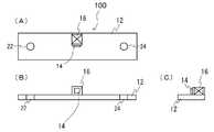
図1は、本発明の第1の実施の形態に係るバスバー一体型電流センサ100の斜視図である。バスバー一体型電流センサ100は、バスバー12と、ホール素子および制御回路を内蔵するIC(Integrated Circuit)14と、フィードバックコイル16とを備える。バスバー12は平板形状(例えば銅板)であり、取付穴22、24を介して被測定電流の経路をなすように取り付けられる。IC14の回路構成については後述する。IC14およびフィードバックコイル16はバスバー12の幅広主面上に固定配置されバスバー12と一体化される。以下、図2も参照してバスバー一体型電流センサ100の形状を詳細に説明する。(First embodiment)
FIG. 1 is a perspective view of a bus bar integrated
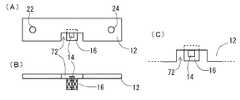
図2は、図1に示されるバスバー一体型電流センサ100の形状説明図であり、(A)は平面図、(B)は正断面図、(C)は右側面図である。 2A and 2B are explanatory views of the shape of the bus bar integrated
フィードバックコイル16は、これに限定されないが、巻線32を施したボビン26の内側に磁気ヨーク(軟磁性体)28を設けて構成される。そして、フィードバックコイル16は、バスバー12の長手方向略中央に固着(例えば接着)され、その軸方向はバスバー12の長手方向と略垂直かつ幅方向と略平行である。フィードバックコイル16の一方の端面はバスバー12の縁に位置し、他方の端面はバスバー12の幅方向略中央に位置する。この他方の端面上略中央にIC14が固着(例えば接着)される。IC14に内蔵されたホール素子の感磁面はコイル16の端面(すなわち磁気ヨーク端面)に対向し、バスバー12の幅方向と略垂直である。したがって、バスバー12に流れる電流によって発生する磁界(以下「第1の磁界」とも表記)とホール素子の感磁面は略垂直となり、また、フィードバックコイル16に流れる電流によって発生する磁界(以下「第2の磁界」とも表記)とホール素子の感磁面も略垂直となる。IC14に内蔵された制御回路は、ホール素子の出力電圧がゼロとなるようにフィードバックコイル16に電流を供給する。これによりホール素子の感磁面においては第1の磁界と第2の磁界とが相殺する。つまり、フィードバックコイル16はホール素子の感磁面に印加される第1の磁界を相殺する第2の磁界を発生する。この第2の磁界を発生するためにフィードバックコイル16に流れる電流に基づいてバスバー12に流れる電流が検出される。 Although not limited to this, the
図3は、図1に示されるバスバー一体型電流センサ100の右側断面図であり、かつ、ホール素子の感磁面における第1の磁界と第2の磁界との関係の概略説明図である。フィードバックコイル16は、これに限定されないが、巻線32を施したボビン26の内側に磁気ヨーク28を設けて構成される。このコイル16の長さはバスバー12の幅広主面の幅よりも十分に短くすることができる。バスバー12に流れる被測定電流I1は紙面手前から奥に向かっているものとする。第1の磁界Hbは被測定電流I1を右ねじ方向に一周するように発生し、これによりIC14に内蔵されたホール素子の感磁面には紙面左から右に向かう磁界が印加される。一方フィードバックコイル16にはホール素子の出力電圧がゼロとなるように電流が供給されるから、第2の磁界Hfはホール素子の感磁面近傍で第1の磁界Hbを相殺するように発生する。すなわちホール素子の感磁面には紙面右から左に向かう磁界が印加され、ホール素子の感磁面に印加される磁界はゼロとなる。FIG. 3 is a right side cross-sectional view of the bus bar integrated
上述した図18に示される従来の磁気平衡式電流センサでは被測定電流が貫通するようにリング状の磁気コア124を設けて実質的な閉磁路を形成し、これにより被測定電流によって発生する磁束をその閉磁路に収束させている。これは「等アンペアターンの原理」を厳密に成り立たせるためと考えられる。しかしこのような構成であると上述の通り磁気コアへの巻線のため形状が大型で重量も大きくなりがちである。これは閉磁路を形成したことにより被測定電流によってギャップ内に発生する磁界(すなわちホール素子の感磁面に印加される磁界)が強いためにそれを打ち消すための磁界も同じように強くすることが必要となるからである。 In the conventional magnetic balance type current sensor shown in FIG. 18 described above, a ring-shaped
これに対して本実施の形態のバスバー一体型電流センサ100は、例えば図3に示される通り、バスバー12を周回せずに、バスバー12の一面のみに対向する短い磁気ヨーク28によって開磁路を形成しているため、被測定電流I1によってホール素子の感磁面に印加される磁界はリング状の磁気コアによって閉磁路を形成した場合と比較して小さい。したがってホール素子の感磁面に印加される磁界をゼロにするためにフィードバックコイル16が発生すべき磁界も小さいため、コイルへの供給電流を同程度とした場合フィードバックコイル16の巻線数はリング状の磁気コアに施す巻線数よりも少なくて済む。すなわち、被測定電流I1と、第2の磁界を発生するためのフィードバックコイル16への供給電流I2と、フィードバックコイル16の巻線数Nと、1より大きい定数kとの間には
1[ターン]×I1[A]=k×N[ターン]×I2[A]
が成立する。図1ないし3に示されるバスバー一体型電流センサ100においてはkは例えば20程度となる。したがって、例えば被測定電流が300Aのときにコイルへの供給電流を30mAに抑えようとした場合、
1[ターン]×300[A]=20×500[ターン]×0.03[A]
であるから、フィードバックコイル16の巻線数は500ターンで済む。
このためバスバー一体型電流センサ100はリング状の磁気コアを用いる従来の磁気平衡式電流センサと比較して小型かつ軽量となっている。また、本実施の形態のバスバー一体型電流センサ100の精度は±1%以下であり、これは図18に示される従来の磁気平衡式電流センサの精度と遜色ないものといえる。On the other hand, the bus bar integrated
Is established. In the bus bar integrated
1 [turn] × 300 [A] = 20 × 500 [turn] × 0.03 [A]
Therefore, the number of windings of the
Therefore, the bus bar integrated
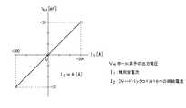
図4は、図1ないし3に示されるバスバー一体型電流センサ100においてフィードバックコイル16への供給電流I2をゼロとした場合のホール素子の出力電圧VH(縦軸)と被測定電流I1(横軸)の特性例を示す。被測定電流I1の−300A〜+300Aのレンジに対してホール素子の出力電圧は−30mV〜+30mVとなり、直線的な特性となっている。FIG. 4 shows the output voltage VH (vertical axis) of the Hall element and the measured current I1 when the supply current I2 to the
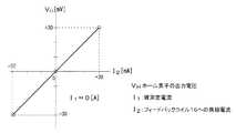
図5は、図1ないし3に示されるバスバー一体型電流センサ100において被測定電流I1をゼロとした場合の、フィードバックコイル16への供給電流I2(横軸)に対するホール素子の出力電圧VH(縦軸)の特性例を示す。フィードバックコイル16への供給電流I2の−30mA〜+30mAのレンジに対してホール素子の出力電圧は−30mV〜+30mVとなり、直線的な特性となっている。FIG. 5 shows the output voltage V of the Hall element with respect to the supply current I2 (horizontal axis) to the
図6は、図1ないし図3に示されるバスバー一体型電流センサ100において、センサ出力として電流出力を得るための回路図である。IC14は、定電流回路42と、ホール素子46と、誤差増幅回路48とを含む。ホール素子46の端子a、c間には定電流回路42によって一定量の電流が供給され、ホール素子46の感磁面に印加された磁界に比例する電圧が端子b、d間に発生する。誤差増幅回路48は、出力端子から電流を吸い込む又は吐き出すことにより、端子b、d間の電位差が常にゼロとなるように、すなわちホール素子46の感磁面において上述の第1の磁界と第2の磁界とが相殺するように、フィードバックコイル16に電流を供給する。ここで供給される電流はモニター用電流計52によって知ることができる。 FIG. 6 is a circuit diagram for obtaining a current output as a sensor output in the bus bar integrated
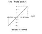
図7は、被測定電流I1(横軸)に対する図6のモニター用電流計52の指示値(縦軸)の特性例を示す。被測定電流I1の−300A〜+300Aのレンジに対してモニター用電流計52の指示値は−30mA〜+30mAとなり、直線的な特性となっている。0.03[A]/300[A]=0.0001=0.01[%]であるから、モニター用電流計52の指示値を1万倍すれば被測定電流I1が得られる。FIG. 7 shows a characteristic example of the indicated value (vertical axis) of the monitoring ammeter 52 of FIG. 6 with respect to the measured current I1 (horizontal axis). The indication value of the monitor ammeter 52 is −30 mA to +30 mA for the range of the current I1 to be measured from −300 A to +300 A, which is a linear characteristic. Since 0.03 [A] / 300 [A] = 0.0001 = 0.01 [%], the current I1 to be measured can be obtained by multiplying the indicated value of the monitor ammeter 52 by 10,000.
図8は、図1ないし図3に示されるバスバー一体型電流センサ100において、センサ出力として電圧出力を得るための回路図である。図6の電流出力タイプと異なるところは、モニター用電流計52に替えて検出抵抗Rsおよび差動増幅回路54を設け、差動増幅回路54の出力電圧Voutをセンサ出力とする点である。検出抵抗Rsはフィードバックコイル16への供給電流を電圧に変換するための微小抵抗であり、その抵抗値は差動増幅回路54の入力インピーダンスよりも十分小さいものとする。差動増幅回路54は、検出抵抗Rsの両端の電圧Vsを増幅し電圧Voutを出力する。 FIG. 8 is a circuit diagram for obtaining a voltage output as a sensor output in the bus bar integrated
差動増幅回路54は、演算増幅器56と、第1抵抗R1〜第4抵抗R4と、基準電圧源Vrefとを含む。ここでは基準電圧源Vrefの電圧は電源電圧Vccの1/2(=2.5V)としている。第1抵抗R1〜第4抵抗R4の抵抗値はR1=R2、R3=R4であり、差動増幅回路54の増幅度はR3/R1である。増幅度は例えば1近傍とする。差動増幅回路54の出力電圧Voutは
Vout=−(R3/R1)Vs+2.5[V]
となる。The
It becomes.
図9は、被測定電流I1(横軸)に対する図8の差動増幅回路54の出力電圧Vout(縦軸)の特性例を示す。被測定電流I1の−300A〜+300Aのレンジに対して差動増幅回路54の出力電圧Voutは0.5V〜4.5Vとなり、直線的な特性となっている。FIG. 9 shows a characteristic example of the output voltage Vout (vertical axis) of the
本実施の形態によれば、以下の効果を奏することができる。
(1) バスバー一体型電流センサ100は、従来の磁気平衡式電流センサと比較して小型かつ軽量である。例えば、バスバー12の幅方向主面の幅内にホール素子および制御回路を内蔵するIC14とフィードバックコイル16とを配置でき、コイル巻数も大幅に低減できる。従って、大きさと重量共に磁気平衡式電流センサと比較して1/10以下とすることができる。
(2) 温度ドリフトが磁気比例式電流センサと比較して改善され、全温度範囲での精度が±1%以下となり、従来の磁気平衡式電流センサと遜色ない高精度を実現することができる。
(3) フィードバックコイル16は、巻線32を施したボビン26の内側に磁気ヨーク28を設けて構成されており、磁気ヨーク28の端面にホール素子の感磁面を対面させることにより、強力なフィードバック磁界(第2の磁界)を発生できる。また、そのフィードバック磁界は感磁面に実質的に垂直となる。According to the present embodiment, the following effects can be achieved.
(1) The bus bar integrated
(2) The temperature drift is improved compared to the magnetic proportional current sensor, the accuracy over the entire temperature range is ± 1% or less, and high accuracy comparable to the conventional magnetic balanced current sensor can be realized.
(3) The
(第2の実施の形態)
図10は、第2の実施の形態の変形例に係るバスバー一体型電流センサの形状説明図であり、(A)は正断面図、(B)は右側断面図である。第1の実施の形態と異なるところは、IC14およびフィードバックコイル16が樹脂58でモールドされ、その外側が磁気シールド体としての磁気シールドケース62で覆われた点である。樹脂58は非磁性であるものとする。磁気シールドケース62は、低周波の磁気的干渉に対してはパーマロイ等、高周波の磁気的干渉に対してはフェライト等を用いて磁気遮蔽することができる。本実施の形態によれば、第1の実施の形態の効果に加え、IC14およびフィードバックコイル16が樹脂58でモールドされるためバスバー12との一体化が確実なものとなり位置ずれを起こしにくい。また、外乱磁気によって生じるセンサ出力への悪影響を低減することができる。(Second Embodiment)
FIG. 10 is an explanatory view of the shape of a bus bar integrated current sensor according to a modification of the second embodiment, in which (A) is a front sectional view and (B) is a right sectional view. The difference from the first embodiment is that the
(第3の実施の形態)
図11は、第3の実施の形態に係るバスバー一体型電流センサの形状説明図であり、(A)は平面図、(B)は正断面図、(C)は平面図の一部拡大図である。以下、第1の実施の形態と異なるところを中心に説明する。(Third embodiment)
FIG. 11 is an explanatory diagram of the shape of the bus bar integrated current sensor according to the third embodiment, in which (A) is a plan view, (B) is a front sectional view, and (C) is a partially enlarged view of the plan view. It is. In the following, the description will be centered on differences from the first embodiment.
バスバー12の長手方向中央には矩形状の切欠部72が設けられている。フィードバックコイル16は一方の端面上略中央にIC14が固着(例えば感磁面がコイル端面に対向するように接着)され、この一方の端面のうちIC14の配置されている部分以外の一部がバスバー12の幅広主面に、IC14の縁と切欠部72の縁とが密接もしくは近接するように固着(例えば接着)されている。したがって、フィードバックコイル16の軸方向はバスバー12の幅広主面と略垂直であり、またIC14に内蔵されたホール素子の感磁面はバスバー12の幅広主面と略平行でありかつ第1の磁界と略垂直となる。また、フィードバックコイル16は平面図において切欠部72内に収まっている。本実施の形態の電流測定の原理は第1の実施の形態と同様である。 A
本実施の形態によれば、第1の実施の形態の効果に加え、IC14の縁と切欠部72の縁とが密接もしくは近接するようにフィードバックコイル16の端面の一部が図11(A)あるいは(C)のようにバスバー12の幅広主面とオーバーラップするため、ホール素子の感磁面がより磁界強度の高いところに配置されることとなり、ホール素子の感磁面に印加される磁界強度が不足するような場合に有効である。また、切欠部72近傍では電流密度が高いため磁界強度が高くなり、このことからも、ホール素子の感磁面に印加される磁界強度が不足するような場合に有効である。 According to the present embodiment, in addition to the effects of the first embodiment, a part of the end surface of the
上記実施の形態は例示であり、それらの各構成要素や各処理プロセスの組合せにいろいろな変形が可能なこと、またそうした変形例も本発明の範囲にあることは当業者に理解されるところである。以下、変形例を列挙する。 Those skilled in the art will understand that the above-described embodiment is an exemplification, and that various modifications can be made to the combination of each component and each treatment process, and such modifications are within the scope of the present invention. . Hereinafter, modifications will be listed.
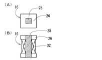
(変形例)
図12は、実施の形態で用いたフィードバックコイル16の形状説明図であり、(A)は平面図、(B)は正断面図である。本図に示されるように実施の形態ではフィードバックコイル16は巻線32を施したボビン26の内側に磁気ヨーク28を設けて構成されるものとしたが、これには限定されず、フィードバックコイル16は空芯コイルや薄膜コイルであってもよい。(Modification)
FIGS. 12A and 12B are explanatory views of the shape of the
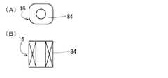
図13は、他の変形例に係るフィードバックコイル16(空芯コイル)の形状説明図であり、(A)は平面図、(B)は正断面図である。本図の場合、フィードバックコイル16は磁気ヨークおよびボビンなしであり、自己融着線(セメントワイヤ)84の巻回による空芯コイルである。ボビンと磁気ヨークを無くすことで、コスト削減、簡素化が可能である。もっとも、磁気ヨークを設けないボビンに巻線したものであってもよい。 FIG. 13 is an explanatory view of the shape of a feedback coil 16 (air-core coil) according to another modification, where (A) is a plan view and (B) is a front sectional view. In the case of this figure, the
図14は、他の変形例に係るフィードバックコイル16(薄膜コイル)の形状説明図である。本図の場合、フィードバックコイル16は絶縁体基板上にスパイラル状の導電パターン74を形成した薄膜コイルである。ホール素子および制御回路を内蔵するIC14はスパイラル状の導電パターン74形成後にその中心に配置することができる。コイルの厚みが小さく、小型化を図ることができる。 FIG. 14 is an explanatory view of the shape of a feedback coil 16 (thin film coil) according to another modification. In the case of this figure, the
図15は、他の変形例に係るバスバー一体型電流センサの左側断面図である。図3に示される第1の実施の形態ではIC14に内蔵されたホール素子の感磁面の一方の側にだけフィードバックコイル16を設けたが、本変形例では一方および他方の側に同様のフィードバックコイルをそれぞれ設けている(図中16A、16B)。本変形例はフィードバックコイルの発生磁界をより強くするときに有効である。また、フィードバックコイル16A、16Bの磁気ヨーク28を一直線上に配置することで、ホール素子の感磁面に対し実質的に垂直な磁界を印加できる。 FIG. 15 is a left sectional view of a bus bar integrated current sensor according to another modification. In the first embodiment shown in FIG. 3, the
図16は、他の変形例に係るバスバー一体型電流センサの左側断面図である。図3に示される第1の実施の形態と異なるところはIC14に内蔵されたホール素子の感磁面の他方の側に磁気ヨーク76を設けた点である。本変形例は、磁気ヨーク76が集磁作用を有するため、ホール素子の感磁面に印加される磁界が不足するような場合に有効である。また、フィードバックコイル16の磁気ヨーク28と磁気ヨーク76とを一直線上に配置することで、ホール素子の感磁面に対し実質的に垂直な磁界を印加できる。 FIG. 16 is a left sectional view of a bus bar integrated current sensor according to another modification. A difference from the first embodiment shown in FIG. 3 is that a
実施の形態ではバスバー12を平板形状としたが、これには限定されず、丸棒その他の形状であってもよい。また、ホール素子は制御回路とともにIC14に内蔵されたが、これにも限定されず、ホール素子と制御回路はそれぞれ別部品であってもよい。また、ホール素子は磁気検出素子の例示であるが、磁気検出素子はこれに限定されず、磁気抵抗効果素子等であってもよい。 In the embodiment, the
12 バスバー
14 IC
16 フィードバックコイル
26 ボビン
28 磁気ヨーク
32 巻線
42 定電流回路
46 ホール素子
48 誤差増幅回路
52 モニター用電流計
54 差動増幅回路
56 演算増幅器
58 樹脂
62 磁気シールドケース
72 切欠部
100 バスバー一体型電流センサ
I1 被測定電流
Rs 検出抵抗
Vref 基準電圧源12
16
Claims (11)
Translated fromJapanese前記バスバーに流れる電流によって発生する第1の磁界が感磁面に印加されるように前記バスバーに対して固定配置された磁気検出素子と、
前記磁気検出素子と近接するよう前記バスバーに対して固定配置され、前記磁気検出素子の感磁面に印加される前記第1の磁界を相殺する第2の磁界を発生するコイルとを備え、
前記第2の磁界を発生するために前記コイルに流れる電流に基づいて前記バスバーに流れる電流を検出する電流センサであり、
前記バスバーに流れる電流をI1、前記第2の磁界を発生するために前記コイルに流れる電流をI2、前記コイルの巻線数をN、1より大きい定数をkとしたとき、前記I1、前記I2、前記Nおよび前記kは、下記(1)式
I1=k×N×I2 …(1)
の関係を満たすことを特徴とするバスバー一体型電流センサ。A bus bar,
A magnetic detection element fixedly arranged with respect to the bus bar so that a first magnetic field generated by a current flowing through the bus bar is applied to a magnetic sensitive surface;
A coil that is fixedly arranged with respect to the bus bar so as to be close to the magnetic detection element and generates a second magnetic field that cancels the first magnetic field applied to the magnetic sensitive surface of the magnetic detection element;
A current sensor that detects a current flowing through the bus bar based on a current flowing through the coil to generate the second magnetic field;
When the current flowing through the bus bar is I1 , the current flowing through the coil to generate the second magnetic field is I2 , the number of windings of the coil is N, and a constant greater than 1 is k1. , I2 , N and k are represented by the following formula (1) I1 = k × N × I2 (1)
A bus bar integrated current sensor characterized by satisfying the above relationship.
前記バスバーに流れる電流によって発生する第1の磁界が感磁面に印加されるように前記バスバーに対して固定配置された磁気検出素子と、
前記磁気検出素子と近接するよう前記バスバーに対して固定配置され、前記磁気検出素子の感磁面に印加される前記第1の磁界を相殺する第2の磁界を発生するコイルとを備え、
前記第2の磁界を発生するために前記コイルに流れる電流に基づいて前記バスバーに流れる電流を検出する電流センサであり、
前記バスバーは平板形状であり、前記磁気検出素子と前記コイルとが、前記バスバーの幅広主面上に固定配置されていることを特徴とするバスバー一体型電流センサ。A bus bar,
A magnetic detection element fixedly arranged with respect to the bus bar so that a first magnetic field generated by a current flowing through the bus bar is applied to a magnetic sensitive surface;
A coil that is fixedly arranged with respect to the bus bar so as to be close to the magnetic detection element and generates a second magnetic field that cancels the first magnetic field applied to the magnetic sensitive surface of the magnetic detection element;
A current sensor that detects a current flowing through the bus bar based on a current flowing through the coil to generate the second magnetic field;
The bus bar has a flat plate shape, and the magnetic detection element and the coil are fixedly arranged on the wide main surface of the bus bar.
Priority Applications (1)
| Application Number | Priority Date | Filing Date | Title |
|---|---|---|---|
| JP2007052190AJP2008215970A (en) | 2007-03-02 | 2007-03-02 | Bus bar integrated current sensor |
Applications Claiming Priority (1)
| Application Number | Priority Date | Filing Date | Title |
|---|---|---|---|
| JP2007052190AJP2008215970A (en) | 2007-03-02 | 2007-03-02 | Bus bar integrated current sensor |
Publications (1)
| Publication Number | Publication Date |
|---|---|
| JP2008215970Atrue JP2008215970A (en) | 2008-09-18 |
Family
ID=39836187
Family Applications (1)
| Application Number | Title | Priority Date | Filing Date |
|---|---|---|---|
| JP2007052190AWithdrawnJP2008215970A (en) | 2007-03-02 | 2007-03-02 | Bus bar integrated current sensor |
Country Status (1)
| Country | Link |
|---|---|
| JP (1) | JP2008215970A (en) |
Cited By (12)
| Publication number | Priority date | Publication date | Assignee | Title |
|---|---|---|---|---|
| US20110199079A1 (en)* | 2010-02-12 | 2011-08-18 | Alps Green Devices Co., Ltd. | Current sensor and battery with current sensor |
| CN102265167A (en)* | 2009-01-19 | 2011-11-30 | 矢崎总业株式会社 | Assembly structure of the current detection device |
| JP2013044705A (en)* | 2011-08-26 | 2013-03-04 | Asahi Kasei Electronics Co Ltd | Current detection device |
| JP2013057629A (en)* | 2011-09-09 | 2013-03-28 | Mitsubishi Electric Corp | Current detector and semiconductor device including the same |
| JP2013148513A (en)* | 2012-01-20 | 2013-08-01 | Aisin Seiki Co Ltd | Current sensor |
| JP2013148512A (en)* | 2012-01-20 | 2013-08-01 | Aisin Seiki Co Ltd | Current sensor |
| JP2014063944A (en)* | 2012-09-24 | 2014-04-10 | Toyota Motor Corp | Reactor |
| JP2014126443A (en)* | 2012-12-26 | 2014-07-07 | Toyota Auto Body Co Ltd | Apparatus and method for inspecting power supply of glass with hot wire |
| US8779756B2 (en) | 2010-05-19 | 2014-07-15 | Denso Corporation | Current sensor |
| KR101927847B1 (en) | 2017-06-26 | 2018-12-13 | 주식회사유성계전 | a transformer with an insulator |
| JP2021019041A (en)* | 2019-07-18 | 2021-02-15 | 株式会社デンソー | Electronic apparatus and printed circuit board |
| WO2022249836A1 (en)* | 2021-05-27 | 2022-12-01 | 株式会社デンソー | Power conversion device |
- 2007
- 2007-03-02JPJP2007052190Apatent/JP2008215970A/ennot_activeWithdrawn
Cited By (16)
| Publication number | Priority date | Publication date | Assignee | Title |
|---|---|---|---|---|
| CN102265167A (en)* | 2009-01-19 | 2011-11-30 | 矢崎总业株式会社 | Assembly structure of the current detection device |
| CN102162820A (en)* | 2010-02-12 | 2011-08-24 | 阿尔卑斯绿色器件株式会社 | Current sensor and battery with current sensor |
| US8421452B2 (en)* | 2010-02-12 | 2013-04-16 | Alps Green Devices Co., Ltd. | Current sensor and battery with current sensor |
| US20110199079A1 (en)* | 2010-02-12 | 2011-08-18 | Alps Green Devices Co., Ltd. | Current sensor and battery with current sensor |
| US8779756B2 (en) | 2010-05-19 | 2014-07-15 | Denso Corporation | Current sensor |
| JP2013044705A (en)* | 2011-08-26 | 2013-03-04 | Asahi Kasei Electronics Co Ltd | Current detection device |
| JP2013057629A (en)* | 2011-09-09 | 2013-03-28 | Mitsubishi Electric Corp | Current detector and semiconductor device including the same |
| JP2013148513A (en)* | 2012-01-20 | 2013-08-01 | Aisin Seiki Co Ltd | Current sensor |
| JP2013148512A (en)* | 2012-01-20 | 2013-08-01 | Aisin Seiki Co Ltd | Current sensor |
| JP2014063944A (en)* | 2012-09-24 | 2014-04-10 | Toyota Motor Corp | Reactor |
| JP2014126443A (en)* | 2012-12-26 | 2014-07-07 | Toyota Auto Body Co Ltd | Apparatus and method for inspecting power supply of glass with hot wire |
| KR101927847B1 (en) | 2017-06-26 | 2018-12-13 | 주식회사유성계전 | a transformer with an insulator |
| JP2021019041A (en)* | 2019-07-18 | 2021-02-15 | 株式会社デンソー | Electronic apparatus and printed circuit board |
| WO2022249836A1 (en)* | 2021-05-27 | 2022-12-01 | 株式会社デンソー | Power conversion device |
| JP2022182166A (en)* | 2021-05-27 | 2022-12-08 | 株式会社デンソー | power converter |
| JP7472853B2 (en) | 2021-05-27 | 2024-04-23 | 株式会社デンソー | Power Conversion Equipment |
Similar Documents
| Publication | Publication Date | Title |
|---|---|---|
| JP2008215970A (en) | Bus bar integrated current sensor | |
| JP4788922B2 (en) | Current sensor | |
| JP4835868B2 (en) | Current sensor | |
| JP7522129B2 (en) | Magnetic Sensors | |
| US8519704B2 (en) | Magnetic-balance-system current sensor | |
| US8754642B2 (en) | Magnetic balance type current sensor | |
| US8638092B2 (en) | Current sensor | |
| US11199593B2 (en) | Magnetic sensor | |
| JP2010071822A (en) | Current sensor | |
| EP3779490B1 (en) | Magnetic sensor | |
| JP7115224B2 (en) | magnetic sensor | |
| JP2010002277A (en) | Current sensor | |
| JP2009210406A (en) | Current sensor and watthour meter | |
| JPWO2014181382A1 (en) | Magnetic current sensor and current measuring method | |
| JPH07146315A (en) | Ac current sensor | |
| JP2019002742A (en) | Current sensor | |
| JP2006038518A (en) | Current measuring instrument | |
| JP6384677B2 (en) | Current sensor | |
| JP2019152473A (en) | Current sensor | |
| CN115667966A (en) | Magnetic field detection device and magnetic field detection device array | |
| JP5704347B2 (en) | Current sensor | |
| US11543469B2 (en) | Current sensor, and electric control apparatus including the current sensor | |
| WO2012060069A1 (en) | Current sensor | |
| JP2013047610A (en) | Magnetic balance type current sensor | |
| JP2005221342A (en) | Coil type current sensor |
Legal Events
| Date | Code | Title | Description |
|---|---|---|---|
| A300 | Withdrawal of application because of no request for examination | Free format text:JAPANESE INTERMEDIATE CODE: A300 Effective date:20100511 |