JP2008215422A - Ball screw for actuator and its screw grooving method - Google Patents
Ball screw for actuator and its screw grooving methodDownload PDFInfo
- Publication number
- JP2008215422A JP2008215422AJP2007050906AJP2007050906AJP2008215422AJP 2008215422 AJP2008215422 AJP 2008215422AJP 2007050906 AJP2007050906 AJP 2007050906AJP 2007050906 AJP2007050906 AJP 2007050906AJP 2008215422 AJP2008215422 AJP 2008215422A
- Authority
- JP
- Japan
- Prior art keywords
- thread groove
- screw
- ball
- groove
- nut
- Prior art date
- Legal status (The legal status is an assumption and is not a legal conclusion. Google has not performed a legal analysis and makes no representation as to the accuracy of the status listed.)
- Pending
Links
- 238000000034methodMethods0.000titleclaimsabstractdescription30
- 230000005540biological transmissionEffects0.000claimsabstractdescription32
- 238000005520cutting processMethods0.000claimsdescription35
- 238000003754machiningMethods0.000claimsdescription18
- 238000010791quenchingMethods0.000claimsdescription10
- 230000000171quenching effectEffects0.000claimsdescription10
- 239000002994raw materialSubstances0.000claimsdescription7
- 230000033001locomotionEffects0.000claimsdescription5
- 238000005480shot peeningMethods0.000claimsdescription5
- 238000010438heat treatmentMethods0.000description17
- 238000005096rolling processMethods0.000description6
- 229910000760Hardened steelInorganic materials0.000description3
- 238000002347injectionMethods0.000description3
- 239000007924injectionSubstances0.000description3
- 239000010410layerSubstances0.000description3
- 244000145845chatteringSpecies0.000description2
- 230000006698inductionEffects0.000description2
- 238000012986modificationMethods0.000description2
- 230000004048modificationEffects0.000description2
- 238000003672processing methodMethods0.000description2
- 229910000954Medium-carbon steelInorganic materials0.000description1
- 229910000831SteelInorganic materials0.000description1
- 239000011324beadSubstances0.000description1
- 230000007423decreaseEffects0.000description1
- 239000002245particleSubstances0.000description1
- 102220259718rs34120878Human genes0.000description1
- 239000010959steelSubstances0.000description1
- 239000002344surface layerSubstances0.000description1
- 230000003746surface roughnessEffects0.000description1
Images


Landscapes
- Transmission Devices (AREA)
Abstract
Description
Translated fromJapanese本発明は、自動車等のアクチュエータに用いられるアクチュエータ用ボールねじに関し、詳しくは、多数のボールが転動する螺旋状のねじ溝が形成され、ナットに支持軸受および電動モータの回転駆動力をナットに伝達するトルク伝達部品が装着されたアクチュエータ用ボールねじおよびそのねじ溝加工方法に関するものである。 The present invention relates to a ball screw for an actuator used for an actuator of an automobile or the like, and more specifically, a helical thread groove on which a large number of balls roll is formed, and the nut is used as a support bearing and the rotational driving force of an electric motor. The present invention relates to a ball screw for an actuator on which a torque transmitting component to be transmitted is mounted and a method for machining the thread groove.
ボールねじは、外周に螺旋状のねじ溝が形成されたボールねじ軸と、円筒面内に螺旋状のねじ溝が形成されたボールねじナットと、対向する両ねじ溝で構成されたボール転動路内に転動自在に収容された多数のボールとからなり、ボールねじ軸あるいはボールねじナットの回転を軸方向の並進運動に変換する機械要素である。 A ball screw has a ball screw shaft composed of a ball screw shaft having a spiral thread groove formed on the outer periphery, a ball screw nut having a spiral thread groove formed in a cylindrical surface, and both opposing screw grooves. It is a mechanical element that is composed of a large number of balls that are rotatably accommodated in the road, and converts the rotation of the ball screw shaft or ball screw nut into translational motion in the axial direction.
従来、自動車用のアクチュエータ等に使用されるボールねじにおいて、そのボールねじ軸またはナットのねじ溝は、生材にねじ溝を旋削する工程と、焼入工程と、ねじ溝を研削する工程を経て加工されている。なお、旋削工程では、ねじ溝と同じ形状の工具(総型バイト)を使用している。 2. Description of the Related Art Conventionally, in a ball screw used in an actuator for an automobile, the thread groove of the ball screw shaft or nut is subjected to a process of turning the thread groove on a raw material, a quenching process, and a process of grinding the thread groove. Has been processed. In the turning process, a tool (total type bite) having the same shape as the thread groove is used.
しかしながら、総型バイトで旋削すると、バイトに対する切削抵抗が大きくて剛性の不足が生じ、バイトの振動、所謂ビビリが生じ易い。その結果、加工精度が悪化すると共に、研削取代を大きく残しておく必要があり、研削工程に時間がかかる。こうした問題を解決するため、本出願人は、ねじ溝の形状変化に容易に対処でき、かつ総加工時間の短縮が図れるボールねじのねじ溝加工方法を既に提案している。 However, when turning with a full-size bite, the cutting resistance against the bite is large and the rigidity is insufficient, so that vibration of the bite, so-called chattering easily occurs. As a result, the machining accuracy deteriorates, and it is necessary to leave a large machining allowance, which takes time for the grinding process. In order to solve these problems, the present applicant has already proposed a method of processing a thread groove of a ball screw that can easily cope with a change in the shape of the thread groove and can reduce the total processing time.
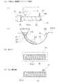
このねじ溝加工方法は、図7に示すように、ねじ軸51におけるねじ溝52の加工を行う方法であって、生材からなるワークWにねじ溝52を旋削する工程と、この旋削したワークWを焼入れする工程と、焼入後のワークWのねじ溝52を研削する工程とを含む。まず、同図(A)に示すように、生材の棒状ワークWにねじ溝52を旋削する。(a)は、ワークWを旋盤の主軸チャック53で把持した状態を示し、(b)は旋削が進んだ段階におけるねじ溝52の拡大断面を示す。この場合の旋削は、所謂ポイント切削で行う。すなわち、切刃54aのノーズRがねじ溝52の曲率半径よりも小さな汎用バイト54を用い、この汎用バイト54をねじ溝52の有効長さ分だけ複数回移動させて、各回の移動経路P1、P2〜Pnをねじ溝52の断面形状の円弧方向に順次ずらせることによりねじ溝52の全体を旋削する。ねじ溝52の旋削が完了した後、ワークWを加熱炉55で焼入れし(図7(B))、この焼入れしたワークWを砥石56で研削してねじ軸51が完成する(図7(C))。
こうした従来の加工方法によると、小さなバイト54でポイント切削を行うので、バイト54の経路変更を行うだけで容易にねじ溝52の形状変更ができ、バイト54に対する切削抵抗が小さくてなってビビリの問題もなく、高精度に旋削が行えるという特徴を有している。然しながら、総型バイトを使用する旋削加工に比べ、ある程度のコスト低減は可能であるが、研削工程は、加工の度に砥石56を成形して形状を管理する必要がある。この研削工程は、ねじ溝52の加工工程全体の加工コストに対して、大きなウェイトを占めているため、さらなる加工コストの低減を図るには限界があった。 According to such a conventional processing method, since point cutting is performed with a
ここで、加工コストの低減を図るには、ポイント切削によりねじ溝52の加工を完了させ、研削加工そのものを廃止することが考えられるが、切削加工でこのねじ溝52を完成形状に仕上げ加工した場合、後工程である熱処理時の変形を抑えることが重要となってくる。特に、図示しないナット回転で使用されるボールねじアクチュエータにおいては、ナット内径にねじ溝が形成されると共に、ナット外径にはこのナットを回転自在に支承するための支持軸受と、電動モータの回転駆動力をナットに伝達する歯車等のトルク伝達部品が装着される。そのため、ナットは均一な肉厚からなる単純な形状とはならず、外径形状が複雑になる。これにより、例え、低コストでねじ溝52を完成形状に仕上げ加工したとしても、熱処理変形による歪みでナットのねじ溝精度が低下し、ボールねじアクチュエータとして所望の精度と耐久性が得られないと言う問題があった。 Here, in order to reduce the processing cost, it is conceivable to complete the processing of the
本発明は、こうした従来の問題に鑑みてなされたもので、所望の精度を確保すると共に、低コストで耐久性に優れたアクチュエータ用ボールねじおよびそのねじ溝加工方法を提供することを目的とする。 The present invention has been made in view of these conventional problems, and an object of the present invention is to provide a ball screw for an actuator and a method for machining the thread groove thereof that ensure desired accuracy and are low in cost and excellent in durability. .
係る目的を達成すべく、本発明のうち請求項1に記載の発明は、外周に螺旋状のねじ溝が形成されたねじ軸と、このねじ軸に外挿され、内周にねじ溝に対応する螺旋状のねじ溝が形成された円筒状のナットと、前記両ねじ溝間に転動自在に収容された多数のボールとを備え、前記ナットが、外周にこのナットを回転自在に支承するための支持軸受が装着され、内周に前記ねじ溝が形成されたボール循環部と、外周に電動モータの回転駆動力を当該ナットに伝達するトルク伝達部品が装着されたトルク伝達部とで構成されたアクチュエータ用ボールねじにおいて、前記ボール循環部が前記トルク伝達部と軸方向に離反して設けられると共に、このトルク伝達部の内周に環状のヌスミ部が形成されている。 In order to achieve such an object, the invention according to
このように、ナットが、外周に支持軸受が装着され、内周に螺旋状のねじ溝が形成されたボール循環部と、外周に電動モータの回転駆動力をナットに伝達するトルク伝達部品が装着されたトルク伝達部とで構成されたアクチュエータ用ボールねじにおいて、ボール循環部がトルク伝達部と軸方向に離反して設けられると共に、このトルク伝達部の内周に環状のヌスミ部が形成されているので、ボール循環部の最小肉厚を厚くすることができると共に、肉厚が不均一となるトルク伝達部に熱処理変形が生じてもボール循環部に影響を及ぼすことがない。したがって、従来の熱処理後の研削加工を廃止して低コスト化を図ることができると共に、所望のねじ溝の精度が確保でき、耐久性に優れたアクチュエータ用ボールねじを提供することができる。 In this way, the nut is mounted with a ball bearing with a support bearing on the outer periphery and a spiral thread groove formed on the inner periphery, and a torque transmission component that transmits the rotational driving force of the electric motor to the nut on the outer periphery. In the ball screw for an actuator composed of the torque transmission portion, the ball circulation portion is provided away from the torque transmission portion in the axial direction, and an annular nuisance portion is formed on the inner periphery of the torque transmission portion. Therefore, the minimum thickness of the ball circulation portion can be increased, and even if heat treatment deformation occurs in the torque transmission portion where the thickness is non-uniform, the ball circulation portion is not affected. Accordingly, it is possible to reduce the cost by eliminating the conventional grinding after the heat treatment, and it is possible to provide a ball screw for an actuator that can ensure the accuracy of a desired screw groove and has excellent durability.
好ましくは、請求項2に記載の発明のように、前記ヌスミ部が所定の範囲に形成され、このヌスミ部を介して前記トルク伝達部の内周に軸方向に延びる円筒部が形成されると共に、この円筒部の内径が前記ねじ溝の内径と略同径に形成されていれば、ボール循環部だけでなく、トルク伝達部の最小肉厚を厚くすることができ、ナットの熱処理変形を抑制することができる。したがって、ねじ溝の研削加工工程を廃止して低コスト化を図ると共に、ねじ溝の精度を高めることができる。 Preferably, as in the invention described in
また、請求項3に記載の発明のように、前記ボール循環部の胴部に複数の駒部材が装着され、この駒部材の内周に前記ねじ溝を連結するための円弧状の連結溝が形成されていれば、多数のボールが無限循環することができると共に、ボール循環部の構成が簡素となりコンパクト化することができる。 Further, as in a third aspect of the present invention, a plurality of piece members are mounted on the body portion of the ball circulation portion, and an arc-shaped connection groove for connecting the screw groove to the inner periphery of the piece member. If formed, a large number of balls can circulate indefinitely, and the configuration of the ball circulator can be simplified and downsized.
また、請求項4に記載の発明のように、前記支持軸受が4点接触玉軸受で構成されていれば、軸方向のすきまを抑制することができ、ボール循環部に交番荷重等が負荷されても振動の発生を防止して騒音の小さいコンパクトなアクチュエータを提供することができる。 Further, if the support bearing is constituted by a four-point contact ball bearing as in the invention described in claim 4, the axial clearance can be suppressed, and an alternating load or the like is applied to the ball circulation portion. However, generation of vibration can be prevented and a compact actuator with low noise can be provided.
また、本発明のうち請求項5に記載の方法発明は、生材からなるワークにねじ溝を旋削する工程と、この旋削したワークを焼入れする工程とを含むアクチュエータ用ボールねじのねじ溝加工方法において、前記旋削工程で、切刃のノーズ半径が前記ねじ溝の溝曲率半径よりも小さな汎用バイトを用い、この汎用バイトを前記ねじ溝の有効長さ分だけ複数回移動させて、各回の移動経路を当該ねじ溝の断面形状の円弧方向に順次ずらせることにより、前記ねじ溝の全体が旋削されると共に、前記焼入れ工程の後に、少なくとも前記ねじ溝にショットピーニングによる仕上げ加工が施されている。 According to a fifth aspect of the present invention, there is provided a method for machining a thread groove of a ball screw for an actuator, comprising a step of turning a thread groove on a workpiece made of raw material and a step of quenching the turned workpiece. In the turning step, a general-purpose tool having a cutting blade nose radius smaller than the groove radius of curvature of the thread groove is used, and the general-purpose tool is moved a plurality of times by the effective length of the thread groove to move each time. By sequentially shifting the path in the arc direction of the cross-sectional shape of the thread groove, the entire thread groove is turned and at least the thread groove is subjected to finish processing by shot peening after the quenching step. .
このように、切刃のノーズ半径をねじ溝の溝曲率半径よりも小さくしてねじ溝がポイント切削によって成形加工されると共に、焼入れ工程の後に、少なくともねじ溝にショットピーニングによる仕上げ加工が施されているので、ねじ溝に所望の表面粗さが得られ、ポイント切削によってねじ溝の成形加工を完了させることができる。したがって、従来の熱処理後の研削加工を廃止することができ、ボールねじの精度・耐久性を確保することができると共に、加工コストを低減したアクチュエータ用ボールねじを提供することができる。 Thus, the nose radius of the cutting edge is made smaller than the groove curvature radius of the thread groove, and the thread groove is formed by point cutting, and at least the thread groove is subjected to finish processing by shot peening after the quenching process. Therefore, a desired surface roughness can be obtained in the thread groove, and the forming process of the thread groove can be completed by point cutting. Therefore, the conventional grinding process after heat treatment can be abolished, the accuracy and durability of the ball screw can be ensured, and the ball screw for an actuator with reduced machining cost can be provided.
本発明に係るアクチュエータ用ボールねじは、外周に螺旋状のねじ溝が形成されたねじ軸と、このねじ軸に外挿され、内周にねじ溝に対応する螺旋状のねじ溝が形成された円筒状のナットと、前記両ねじ溝間に転動自在に収容された多数のボールとを備え、前記ナットが、外周にこのナットを回転自在に支承するための支持軸受が装着され、内周に前記ねじ溝が形成されたボール循環部と、外周に電動モータの回転駆動力を当該ナットに伝達するトルク伝達部品が装着されたトルク伝達部とで構成されたアクチュエータ用ボールねじにおいて、前記ボール循環部が前記トルク伝達部と軸方向に離反して設けられると共に、このトルク伝達部の内周に環状のヌスミ部が形成されているので、ボール循環部の最小肉厚を厚くすることができると共に、肉厚が不均一となるトルク伝達部に熱処理変形が生じてもボール循環部に影響を及ぼすことがない。したがって、従来の熱処理後の研削加工を廃止して低コスト化を図ることができると共に、所望のねじ溝の精度が確保でき、耐久性に優れたアクチュエータ用ボールねじを提供することができる。The ball screw for an actuator according to the present invention has a screw shaft having a spiral thread groove formed on the outer periphery thereof, and is extrapolated to the screw shaft, and a spiral screw groove corresponding to the screw groove is formed on the inner periphery thereof. A cylindrical nut and a large number of balls rotatably accommodated between the two screw grooves, and the nut is mounted on the outer periphery with a support bearing for rotatably supporting the nut; In the ball screw for an actuator, the ball circulating portion having a screw groove formed on the outer periphery thereof, and a torque transmission portion having a torque transmission component mounted on the outer periphery thereof to transmit the rotational driving force of the electric motor to the nut. Since the circulating portion is provided away from the torque transmitting portion in the axial direction and an annular nuisance portion is formed on the inner periphery of the torque transmitting portion, the minimum thickness of the ball circulating portion can be increased. Together with A wall thickness does not affect the ball circulation portion even when the heat treatment deformation torque transmitting portion becomes uneven. Accordingly, it is possible to reduce the cost by eliminating the conventional grinding after the heat treatment, and it is possible to provide a ball screw for an actuator that can ensure the accuracy of a desired screw groove and has excellent durability.
外周に螺旋状のねじ溝が形成されたねじ軸と、このねじ軸に外挿され、内周にねじ溝に対応する螺旋状のねじ溝が形成された円筒状のナットと、前記両ねじ溝間に転動自在に収容された多数のボールとを備え、前記ナットが、外周にこのナットを回転自在に支承するための支持軸受が装着され、内周に前記ねじ溝が形成されたボール循環部と、外周に電動モータの回転駆動力を当該ナットに伝達するトルク伝達部品が装着されたトルク伝達部とで構成されたアクチュエータ用ボールねじにおいて、前記ボール循環部が前記トルク伝達部と軸方向に離反して設けられ、このトルク伝達部の内周に環状のヌスミ部と、このヌスミ部を介して軸方向に延びる円筒部が形成されると共に、この円筒部の内径が前記ねじ溝の内径と略同径に形成されている。 A screw shaft having a spiral thread groove formed on the outer periphery, a cylindrical nut formed on the inner periphery and having a spiral thread groove corresponding to the screw groove, and both the thread grooves A ball circulation circuit comprising a plurality of balls rotatably accommodated between the nuts, a support bearing for rotatably supporting the nuts on the outer periphery, and a thread groove formed on the inner periphery. And a ball screw for an actuator having a torque transmission part mounted with a torque transmission component that transmits the rotational driving force of the electric motor to the nut on the outer periphery. Are formed on the inner periphery of the torque transmitting portion, and a cylindrical portion extending in the axial direction is formed through the pussy portion. The inner diameter of the cylindrical portion is the inner diameter of the thread groove. And is formed with the same diameter .
以下、本発明の実施の形態を図面に基いて詳細に説明する。
図1は、本発明に係るアクチュエータ用ボールねじの第1の実施形態を示す縦断面図、図2は、図1の要部断面図、図3は、本発明に係るねじ軸のねじ溝加工状態を示す説明図、図4は、本発明に係るナットのねじ溝加工状態を示す説明図、図5は、本発明に係るねじ軸のねじ溝加工工程におけるねじ溝の拡大断面図である。Hereinafter, embodiments of the present invention will be described in detail with reference to the drawings.
FIG. 1 is a longitudinal sectional view showing a first embodiment of a ball screw for an actuator according to the present invention, FIG. 2 is a sectional view of an essential part of FIG. 1, and FIG. 3 is a thread groove machining of a screw shaft according to the present invention. FIG. 4 is an explanatory view showing a state of thread groove machining of a nut according to the present invention, and FIG. 5 is an enlarged sectional view of the thread groove in the thread groove machining step of the screw shaft according to the present invention.
このアクチュエータ用ボールねじ1は、S55C等の中炭素鋼やSCM415等の肌焼き鋼からなり、外周に螺旋状のねじ溝2aが形成されたねじ軸2と、このねじ軸2に外挿され、内周にねじ溝2aに対応する螺旋状のねじ溝3aが形成された円筒状のナット3と、両ねじ溝2a、3a間に転動自在に収容された多数のボール4とを備えている。 The
ナット3はSCM430等の肌焼き鋼からなり、一端部に配されたボール循環部6と、他端部に配されたトルク伝達部7とで構成されている。ボール循環部6は、図2に示すように、その胴部に複数の駒部材5と、外周にナット3を回転自在に支承するための支持軸受8が装着されている。駒部材5の内周にはねじ溝3aを連結するための円弧状の連結溝5aが形成されており、この連結溝5aと両ねじ溝2a、3aによりボール転動路が構成され、多数のボール4が無限循環することができる。また、駒方式を採用することによりボール循環部6の構成が簡素となりコンパクト化することができる。 The
また、支持軸受8は4点接触玉軸受からなり、図示しないハウジングに嵌合され、内周にゴシックアーチ状の外側転走面9aが形成された外輪9と、この外輪9に内嵌され、外周に外側転走面9aに対向するゴシックアーチ状の内側転走面10aが形成された内輪10と、両転走面9a、10a間に保持器(図示せず)を介して転動自在に収容された複数のボール11とを備えている(図1参照)。この支持軸受8は、軸方向のすきまを抑制することができ、ボール循環部6に交番荷重等が負荷されても振動の発生を防止して騒音の小さいコンパクトなアクチュエータを提供することができる。なお、支持軸受8は例示した4点接触玉軸受に限らず、深溝玉軸受やアンギュラ玉軸受、あるいはこのアンギュラ玉軸受を複列に組み合せたもの、さらに複列アンギュラ玉軸受であっても良い。 Further, the support bearing 8 is a four-point contact ball bearing, and is fitted into a housing (not shown), and an
本実施形態では、ねじ溝2a、3aは、ボール4の半径よりも僅かに大きい曲率半径からなる2つの円弧を組み合わせたゴシックアーチ溝に形成されている。無論、ねじ溝2a、3aは、このゴシックアーチ形状以外にも、ボール4とサーキュラコンタクトする円弧状の形状であっても良い。 In the present embodiment, the
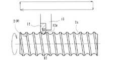
図3は、ねじ軸2におけるねじ溝2aの加工状態を示している。生材の棒状ワークW(2)が図示しない旋盤の主軸チャックで把持され、所定の方向に回転された状態で汎用バイト12によって旋削加工される。このバイト12は、径方向に進退自在に、かつ軸方向に移動自在に支持されたホルダー13に固定されている。この場合の旋削は、所謂ポイント切削で行われる。すなわち、バイト12の切刃12aのノーズ半径R2が、ねじ溝2aの溝曲率半径R1よりも小さな汎用バイト12を用い、このバイト12をねじ溝2aの有効長さ分だけ複数回移動させてねじ溝2aの成形が行われる。 FIG. 3 shows a processed state of the
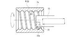
一方、図4に、本発明に係るナット3におけるねじ溝3aの加工状態を示す。前述したねじ軸2におけるねじ溝2aの加工と同様、生材の筒状ワークW(3)が図示しない旋盤の主軸チャックで把持され、所定の方向に回転された状態で汎用バイト14によって旋削加工される。このバイト14は、径方向に進退自在に、かつ軸方向に移動自在に支持されたホルダー15に固定されている。この場合の旋削もポイント切削で行われる。すなわち、バイト14の切刃14aのノーズ半径R4が、ねじ溝3aの溝曲率半径R3よりも小さな汎用バイト14を用い、バイト14をねじ溝3aの有効長さ分だけ複数回移動させて、各回の移動経路をねじ溝3aの円弧方向に順次ずらせることによりねじ溝3aが旋削される。 On the other hand, the processing state of the
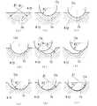
次に、図5(a)〜(j)を用いてねじ軸2におけるねじ溝2aの加工工程を詳細に説明する。なお、ナット3のねじ溝3aにおいても基本的には同様であるので、ここでは省略する。
図5(a)は、旋削加工前の棒状の生材を示し、(b)〜(d)の順に、切刃12aがワークWの軸心方向に送られて、ねじ溝2aの概略形状がバイト12の切刃12aによって成形される。ここで、切刃12aのノーズ半径R2をねじ溝2aの溝曲率半径R1に近付けて寸法設定することにより、切刃12aを軸方向に移動させることなくねじ溝2aの概略形状が得られ、加工時間を短縮することができる。Next, the machining process of the
Fig.5 (a) shows the rod-shaped raw material before turning, the
そして、(e)に示すように、ねじ溝2aの旋削加工がある程度進んだ段階でポイント切削が開始される。(e)〜(j)に示すように、切刃12aをねじ溝2aの有効長さ分だけ複数回移動させて、各回の移動経路をねじ溝2aの円弧方向に順次ずらせることによりねじ溝2aの全体形状が旋削される。 Then, as shown in (e), point cutting is started when the turning of the
なお、本実施例では、ねじ溝2aがゴシックアーチ形状であっても、バイト12の切刃12aのノーズ半径R2がねじ溝2aの溝曲率半径R1よりも小さく設定されているので、加工するねじ溝2aと対向するねじ溝2aに干渉することはなく、ポイント切削によってねじ溝2aの成形加工を完了させることができる。 In the present embodiment, even if the
さらに、本実施例では、ポイント切削によってねじ溝2a、3aの成形加工を完了させた後、熱処理によってその表面に55〜62HRCの範囲の硬化処理が施されている。熱処理は、浸炭焼入れでも高周波誘導加熱による焼入れでも良いが、表層に粒界酸化層が抑制でき、また、局部加熱ができて硬化層深さの設定が比較的容易にできる高周波焼入れが好適である。 Further, in this embodiment, after the forming of the
そして、熱処理によりねじ溝2a、3a等に付着したスケールや表層の粒界酸化層を除去するためにショットピーニングによる仕上げ加工(図示せず)が行われている。このショットピーニングは、スチールビーズの粒径を20〜100μm、噴射時間は約90秒、噴射圧は1〜3kg/cm2、噴射ノズルとワークの表面までの距離は略140mmとした。Then, finish processing (not shown) by shot peening is performed in order to remove scales and surface grain boundary oxide layers attached to the
ここで、トルク伝達部7は、図1に示すように、前述したボール循環部6と軸方向に離反して設けられ、外周に電動モータ(図示せず)の回転駆動力をナット3に伝達する歯車16が固定ナット17を介して軸方向に位置決め固定されると共に、内周には軸方向に延びる環状のヌスミ部18が形成されている。歯車16は、ナット3の外周に形成されたキー溝19に介装されたキー20によってトルク伝達可能に固定されている。なお、ここでは、キー20によって歯車16をナット3に固定するようにしたが、これに限らず、インボリュートスプライン係合やローレット等の圧入固定手段であっても良い。 Here, as shown in FIG. 1, the
一方、ヌスミ部18は、ねじ溝3の溝底径よりも僅かに大径に形成され、この部位にはボール循環部6のねじ溝3aは形成されていない。このように、本実施形態では、トルク伝達部7がボール循環部6と軸方向に離反して設けられ、外周にキー溝19が形成されて歯車16がキー20を介して固定されると共に、内周に環状のヌスミ部18が形成されているので、ボール循環部6の最小肉厚を厚くすることができると共に、肉厚が不均一となるキー溝19部分に熱処理変形が生じてもボール循環部6に影響を及ぼすことがない。したがって、従来の熱処理後の研削加工を廃止して低コスト化を図ることができると共に、所望のねじ溝3aの精度が確保でき、耐久性に優れたアクチュエータ用ボールねじ1を提供することができる。 On the other hand, the
図6は、本発明に係るアクチュエータ用ボールねじの第2の実施形態を示す縦断面図である。なお、この実施形態は、前述した第1の実施形態と基本的にはナットの構成が一部異なるだけで、その他前述した実施形態と同一部品同一部位あるいは同様の機能を有する部位等には同じ符号を付して詳細な説明を省略する。 FIG. 6 is a longitudinal sectional view showing a second embodiment of the ball screw for an actuator according to the present invention. Note that this embodiment is basically the same as the first embodiment described above except that the configuration of the nut is partially different, and other parts that are the same as or similar to the above-described embodiment. Reference numerals are assigned and detailed description is omitted.
このナット21はSCM430等の肌焼き鋼からなり、一端部に配されたボール循環部6と、他端部に配されたトルク伝達部22とで構成されている。このトルク伝達部22は、ボール循環部6と軸方向に離反して設けられ、外周に電動モータ(図示せず)の回転駆動力をナット21に伝達する歯車16が固定ナット17を介して軸方向に位置決め固定されている。また、内周には環状のヌスミ部23がキー溝19の近傍まで形成されると共に、このヌスミ部23を介して軸方向に延びる円筒部24が形成されている。なお、この円筒部24の内径はねじ溝3の内径と略同径に形成され、この部位にはボール循環部6のねじ溝3aは形成されていない。 The
このように、本実施形態では、トルク伝達部22がボール循環部6と軸方向に離反して設けられ、内周に形成された環状のヌスミ部23を介して円筒部24が形成されているので、ボール循環部6だけでなく、肉厚が不均一となるキー溝19部分の最小肉厚を厚くすることができ、ナット21の熱処理変形を抑制することができる。したがって、ねじ溝3aの研削加工工程を廃止して低コスト化を図ると共に、前述した実施形態よりもねじ溝3aの精度を高めることができる。 Thus, in this embodiment, the
以上、本発明の実施の形態について説明を行ったが、本発明はこうした実施の形態に何等限定されるものではなく、あくまで例示であって、本発明の要旨を逸脱しない範囲内において、さらに種々なる形態で実施し得ることは勿論のことであり、本発明の範囲は、特許請求の範囲の記載によって示され、さらに特許請求の範囲に記載の均等の意味、および範囲内のすべての変更を含む。 The embodiment of the present invention has been described above, but the present invention is not limited to such an embodiment, and is merely an example, and various modifications can be made without departing from the scope of the present invention. Of course, the scope of the present invention is indicated by the description of the scope of claims, and further, the equivalent meanings described in the scope of claims and all modifications within the scope of the scope of the present invention are included. Including.
本発明に係るアクチュエータ用ボールねじは、特に自動車等のアクチュエータに用いられ、ナットに支持軸受および電動モータの回転駆動力をナットに伝達するトルク伝達部品が装着されたアクチュエータ用ボールねじに適用できる。 The ball screw for an actuator according to the present invention is used particularly for an actuator of an automobile or the like, and can be applied to a ball screw for an actuator in which a support bearing and a torque transmission component that transmits the rotational driving force of an electric motor are attached to the nut.
1・・・・・・・・・・・アクチュエータ用ボールねじ
2・・・・・・・・・・・ねじ軸
2a、3a・・・・・・・ねじ溝
3、21・・・・・・・・ナット
4、11・・・・・・・・ボール
5・・・・・・・・・・・駒部材
5a・・・・・・・・・・連結溝
6・・・・・・・・・・・ボール循環部
7、22・・・・・・・・トルク伝達部
8・・・・・・・・・・・支持軸受
9・・・・・・・・・・・外輪
10・・・・・・・・・・内輪
12、14・・・・・・・汎用バイト
12a、14a・・・・・切刃
13、15・・・・・・・ホルダー
16・・・・・・・・・・歯車
17・・・・・・・・・・固定ナット
18、23・・・・・・・ヌスミ部
19・・・・・・・・・・キー溝
20・・・・・・・・・・キー
24・・・・・・・・・・円筒部
51・・・・・・・・・・ねじ軸
52・・・・・・・・・・ねじ溝
53・・・・・・・・・・主軸チャック
54・・・・・・・・・・汎用バイト
54a・・・・・・・・・切刃
55・・・・・・・・・・加熱炉
56・・・・・・・・・・砥石
P1〜Pn・・・・・・・バイトの移動経路
R1、R3・・・・・・・ねじ溝の溝曲率半径
R2、R4・・・・・・・切刃のノーズ半径
W・・・・・・・・・・・ワーク1. Ball screw for
Claims (5)
Translated fromJapaneseこのねじ軸に外挿され、内周にねじ溝に対応する螺旋状のねじ溝が形成された円筒状のナットと、
前記両ねじ溝間に転動自在に収容された多数のボールとを備え、
前記ナットが、外周にこのナットを回転自在に支承するための支持軸受が装着され、内周に前記ねじ溝が形成されたボール循環部と、外周に電動モータの回転駆動力を当該ナットに伝達するトルク伝達部品が装着されたトルク伝達部とで構成されたアクチュエータ用ボールねじにおいて、
前記ボール循環部が前記トルク伝達部と軸方向に離反して設けられると共に、このトルク伝達部の内周に環状のヌスミ部が形成されていることを特徴とするアクチュエータ用ボールねじ。A screw shaft having a helical thread formed on the outer periphery;
A cylindrical nut that is extrapolated to the screw shaft and has a spiral thread groove corresponding to the thread groove on the inner periphery;
A plurality of balls accommodated in a freely rollable manner between the both screw grooves,
The nut is mounted on the outer periphery with a support bearing for rotatably supporting the nut, the ball circulation part having the thread groove formed on the inner periphery, and the rotational driving force of the electric motor on the outer periphery is transmitted to the nut. In a ball screw for an actuator configured with a torque transmission part to which a torque transmission component is mounted,
The ball screw for an actuator is characterized in that the ball circulation portion is provided apart from the torque transmission portion in the axial direction, and an annular nuisance portion is formed on the inner periphery of the torque transmission portion.
Priority Applications (1)
| Application Number | Priority Date | Filing Date | Title |
|---|---|---|---|
| JP2007050906AJP2008215422A (en) | 2007-03-01 | 2007-03-01 | Ball screw for actuator and its screw grooving method |
Applications Claiming Priority (1)
| Application Number | Priority Date | Filing Date | Title |
|---|---|---|---|
| JP2007050906AJP2008215422A (en) | 2007-03-01 | 2007-03-01 | Ball screw for actuator and its screw grooving method |
Publications (1)
| Publication Number | Publication Date |
|---|---|
| JP2008215422Atrue JP2008215422A (en) | 2008-09-18 |
Family
ID=39835707
Family Applications (1)
| Application Number | Title | Priority Date | Filing Date |
|---|---|---|---|
| JP2007050906APendingJP2008215422A (en) | 2007-03-01 | 2007-03-01 | Ball screw for actuator and its screw grooving method |
Country Status (1)
| Country | Link |
|---|---|
| JP (1) | JP2008215422A (en) |
Cited By (3)
| Publication number | Priority date | Publication date | Assignee | Title |
|---|---|---|---|---|
| JP2010090953A (en)* | 2008-10-07 | 2010-04-22 | Ntn Corp | Ball screw and pulley width driving mechanism with the same for v-belt type continuously variable transmission |
| US8118656B2 (en) | 2005-02-17 | 2012-02-21 | Sega Corporation | Game device |
| JP5418667B2 (en)* | 2010-03-17 | 2014-02-19 | 日本精工株式会社 | Ball screw and ball screw nut manufacturing method |
Citations (2)
| Publication number | Priority date | Publication date | Assignee | Title |
|---|---|---|---|---|
| JPS59131059A (en)* | 1983-11-28 | 1984-07-27 | Hiroshi Teramachi | Ball screw with angular contact ball bearing |
| JP2005212593A (en)* | 2004-01-29 | 2005-08-11 | Ntn Corp | Electric power steering device |
- 2007
- 2007-03-01JPJP2007050906Apatent/JP2008215422A/enactivePending
Patent Citations (2)
| Publication number | Priority date | Publication date | Assignee | Title |
|---|---|---|---|---|
| JPS59131059A (en)* | 1983-11-28 | 1984-07-27 | Hiroshi Teramachi | Ball screw with angular contact ball bearing |
| JP2005212593A (en)* | 2004-01-29 | 2005-08-11 | Ntn Corp | Electric power steering device |
Cited By (5)
| Publication number | Priority date | Publication date | Assignee | Title |
|---|---|---|---|---|
| US8118656B2 (en) | 2005-02-17 | 2012-02-21 | Sega Corporation | Game device |
| JP2010090953A (en)* | 2008-10-07 | 2010-04-22 | Ntn Corp | Ball screw and pulley width driving mechanism with the same for v-belt type continuously variable transmission |
| JP5418667B2 (en)* | 2010-03-17 | 2014-02-19 | 日本精工株式会社 | Ball screw and ball screw nut manufacturing method |
| US9737926B2 (en) | 2010-03-17 | 2017-08-22 | Nsk Ltd. | Ball screw and manufacturing method of nut for ball screw |
| EP2532924A4 (en)* | 2010-03-17 | 2018-04-25 | NSK Ltd. | Ball screw, manufacturing method of nut for ball screw |
Similar Documents
| Publication | Publication Date | Title |
|---|---|---|
| JP6090436B2 (en) | Method of manufacturing race ring member and metal material for race ring member | |
| JP2008275095A (en) | Ball screw and manufacturing method thereof | |
| JP2008281063A (en) | Ball screw mechanism | |
| CN203272651U (en) | Lead screw shaft and ball screw | |
| JP2011255834A (en) | Rack shaft, method of manufacturing the same, and rack pinion type steering gear unit | |
| JP2005083549A (en) | Ball screw nut and its manufacturing method | |
| JP5121656B2 (en) | Ball screw | |
| JP2008215422A (en) | Ball screw for actuator and its screw grooving method | |
| JP6365796B1 (en) | Track groove processing method, ball screw device, machine and vehicle manufacturing method | |
| US20070137350A1 (en) | Ball screw nut and method of producing the same | |
| JP4679257B2 (en) | Thread groove processing method for ball screw shaft | |
| JP2006266310A (en) | Electric linear actuator | |
| JP2009191902A (en) | Wheel bearing device | |
| JP2012180091A (en) | Bearing device for wheel | |
| JP2005090570A (en) | Ball screw nut and manufacturing method thereof | |
| JP2010043691A (en) | Constant velocity universal joint and method for manufacturing the same | |
| JP2012189217A (en) | Wheel bearing device | |
| JP4467349B2 (en) | Ball screw for automobile | |
| JP2007016848A (en) | Ball screw nut and manufacturing method thereof | |
| JP2014109319A (en) | Ball screw mechanism | |
| JP4993705B2 (en) | Ball screw and thread groove machining method thereof | |
| JP5708552B2 (en) | Method for manufacturing variator part of continuously variable transmission and hard broach tool used in this method | |
| JP2005273870A (en) | Rolling bearing device for vehicle wheel | |
| JP2009191907A (en) | Wheel bearing device | |
| JP2009185831A (en) | Inside joint member for constant velocity universal joint and method for manufacturing the same, and constant velocity universal joint |
Legal Events
| Date | Code | Title | Description |
|---|---|---|---|
| A621 | Written request for application examination | Free format text:JAPANESE INTERMEDIATE CODE: A621 Effective date:20100226 | |
| A977 | Report on retrieval | Free format text:JAPANESE INTERMEDIATE CODE: A971007 Effective date:20110816 | |
| A131 | Notification of reasons for refusal | Effective date:20110818 Free format text:JAPANESE INTERMEDIATE CODE: A131 | |
| A521 | Written amendment | Effective date:20111014 Free format text:JAPANESE INTERMEDIATE CODE: A523 | |
| A02 | Decision of refusal | Free format text:JAPANESE INTERMEDIATE CODE: A02 Effective date:20120327 |