JP2008213647A - Parking assist method and parking assist system - Google Patents
Parking assist method and parking assist systemDownload PDFInfo
- Publication number
- JP2008213647A JP2008213647AJP2007053146AJP2007053146AJP2008213647AJP 2008213647 AJP2008213647 AJP 2008213647AJP 2007053146 AJP2007053146 AJP 2007053146AJP 2007053146 AJP2007053146 AJP 2007053146AJP 2008213647 AJP2008213647 AJP 2008213647A
- Authority
- JP
- Japan
- Prior art keywords
- vehicle
- image
- parking frame
- parking
- target parking
- Prior art date
- Legal status (The legal status is an assumption and is not a legal conclusion. Google has not performed a legal analysis and makes no representation as to the accuracy of the status listed.)
- Pending
Links
- 238000000034methodMethods0.000titleclaimsabstractdescription20
- 238000013459approachMethods0.000claimsabstractdescription10
- 230000002093peripheral effectEffects0.000claimsdescription13
- 239000002131composite materialSubstances0.000abstractdescription34
- 238000006243chemical reactionMethods0.000description19
- 240000004050Pentaglottis sempervirensSpecies0.000description17
- 235000004522Pentaglottis sempervirensNutrition0.000description17
- 238000004364calculation methodMethods0.000description9
- 239000000203mixtureSubstances0.000description9
- 238000013500data storageMethods0.000description7
- 230000000694effectsEffects0.000description3
- 238000001514detection methodMethods0.000description2
- 238000010586diagramMethods0.000description2
- 238000003708edge detectionMethods0.000description2
- 238000005192partitionMethods0.000description2
- 238000003672processing methodMethods0.000description2
- 230000007935neutral effectEffects0.000description1
- 230000002194synthesizing effectEffects0.000description1
Images


Landscapes
- Fittings On The Vehicle Exterior For Carrying Loads, And Devices For Holding Or Mounting Articles (AREA)
- Image Processing (AREA)
- Image Analysis (AREA)
Abstract
Description
Translated fromJapanese本発明は、駐車支援方法及び駐車支援装置に関する。 The present invention relates to a parking assistance method and a parking assistance device.
従来より、車両後方を撮影した映像をディスプレイに表示する駐車支援装置が知られている。この装置は、車両後端に取り付けられた車載カメラから画像データを入力し、その画像データに基づく周辺画像を、ガイド線とともに運転席近傍に設けられたディスプレイに出力する(例えば、特許文献1参照)。 2. Description of the Related Art Conventionally, parking assist devices that display an image of the rear of a vehicle on a display are known. This device inputs image data from a vehicle-mounted camera attached to the rear end of the vehicle, and outputs a peripheral image based on the image data to a display provided in the vicinity of the driver's seat together with a guide line (for example, see Patent Document 1). ).
周辺画像には、自車両から所定距離範囲の路面や障害物が表示されるとともに、自車画像が表示されている。この自車画像は、車載カメラの画角に含まれる車体の一部や、駐車支援装置が予め記憶した車両画像データに基づき描画した画像であって、周辺画像のうち、自車両の現在位置に相当する位置に固定されて表示されている。ドライバーは、周辺画像に駐車枠を区画する白線が表示された際に、その白線と車両との相対位置を把握しながら、ステアリング操作を行うことができる。
しかし、上記した装置では、自車画像を固定して表示し、周辺画像は自車両の後退に伴い変化するため、ドライバーによっては自車両と駐車枠との相対位置がわかりにくいことがある。例えば、車両が左後方に旋回すると、周辺画像が描画する路面は、旋回に伴い、現在位置で車載カメラが撮影可能な路面から、旋回後の位置で車載カメラが撮影可能な路面へと変化する。このため、自車両が駐車枠に進入開始する段階となり、周辺画像に白線が表示されても、その白線が画面内で移動してしまう。従って、路面に標示された駐車枠に対する車両位置を直ぐに把握することができない場合がある。 However, in the above-described device, the host vehicle image is fixed and displayed, and the surrounding image changes as the host vehicle moves backward, so that the relative position between the host vehicle and the parking frame may be difficult to understand depending on the driver. For example, when the vehicle turns to the left rear, the road surface drawn by the surrounding image changes from a road surface that can be photographed by the in-vehicle camera at the current position to a road surface that can be photographed by the in-vehicle camera at the position after the turn. . For this reason, when the own vehicle starts entering the parking frame, even if a white line is displayed in the surrounding image, the white line moves within the screen. Therefore, the vehicle position with respect to the parking frame marked on the road surface may not be immediately grasped.
本発明は、上記問題点に鑑みてなされたものであり、その目的は、自車両と駐車枠との相対位置を直ちに把握することができる駐車支援方法及び駐車支援装置を提供することにある。 The present invention has been made in view of the above problems, and an object of the present invention is to provide a parking support method and a parking support device that can immediately grasp the relative position between the host vehicle and the parking frame.
上記問題点を解決するために、請求項1に記載の発明は、車両周辺の画像を表示手段に表示する駐車支援方法において、車両周辺画像を前記表示手段に出力し、前記車両周辺画像のうち、前記車両の現在位置に相当する位置に自車画像を描画するとともに、前記車両が駐車枠に接近した際に、該駐車枠を所定位置に固定して前記車両周辺画像を描画し、前記車両の後退に伴い、前記自車画像を前記車両周辺画像上で移動することを要旨とする。 In order to solve the above problem, the invention according to
請求項2に記載の発明は、車両周辺の画像を表示手段に表示する駐車支援装置において、車両周辺画像を前記表示手段に出力する周辺画像描画手段と、前記車両周辺画像のうち、前記車両の現在位置に相当する位置に自車画像を描画する自車画像描画手段と、前記車両が駐車枠に接近した際に、該駐車枠を所定位置に固定して前記車両周辺画像を描画し、前記車両の後退に伴い、前記自車画像を前記車両周辺画像上で移動する描画切替手段とを備えたことを要旨とする。 According to a second aspect of the present invention, in the parking assist device for displaying an image around the vehicle on the display means, a surrounding image drawing means for outputting the vehicle surrounding image to the display means, and the vehicle surrounding image out of the vehicle surrounding images. Vehicle image drawing means for drawing the vehicle image at a position corresponding to the current position; and when the vehicle approaches the parking frame, the parking frame is fixed at a predetermined position to draw the vehicle peripheral image, The gist of the present invention is that it includes drawing switching means for moving the vehicle image on the vehicle peripheral image as the vehicle moves backward.
請求項3に記載の発明は、請求項2に記載の駐車支援装置において、前記描画切替手段は、前記駐車枠の全領域が前記表示手段の画像表示範囲に含まれた場合に、該駐車枠を所
定位置に固定して描画した前記車両周辺画像を描画することを要旨とする。According to a third aspect of the present invention, in the parking assist device according to the second aspect, the drawing switching unit is configured such that when the entire area of the parking frame is included in the image display range of the display unit, the parking frame The gist of the present invention is to draw the vehicle peripheral image drawn with the position fixed at a predetermined position.
請求項4に記載の発明は、請求項2又は3に記載の駐車支援装置において、前記描画切替手段は、前記車両周辺画像に表示された前記駐車枠が、前記車両に対して平行になった場合に、該駐車枠を所定位置に固定して描画した前記車両周辺画像を描画することを要旨とする。 According to a fourth aspect of the present invention, in the parking assist device according to the second or third aspect, the drawing switching means is configured such that the parking frame displayed in the vehicle peripheral image is parallel to the vehicle. In this case, the gist is to draw the vehicle periphery image drawn with the parking frame fixed at a predetermined position.
請求項5に記載の発明は、請求項2〜4のいずれか1項に記載の駐車支援装置において、前記描画切替手段は、前記駐車枠の表示位置を、画像表示範囲のうち下方中央にした状態で前記車両周辺画像を表示することを要旨とする。 According to a fifth aspect of the present invention, in the parking assist device according to any one of the second to fourth aspects, the drawing switching means sets the display position of the parking frame to the lower center of the image display range. The gist is to display the vehicle periphery image in a state.
請求項1に記載の発明によれば、車両が駐車枠に接近した際に、駐車枠を所定位置に固定した状態で車両周辺画像が表示される。このため、車両の後退に伴い、固定された目駐車枠に自車画像が移動していくので、ドライバーが違和感を感じず、車両と目標駐車枠との相対位置を直ちに理解できる画面を表示することができる。 According to the first aspect of the present invention, when the vehicle approaches the parking frame, the vehicle peripheral image is displayed with the parking frame fixed at a predetermined position. For this reason, as the vehicle moves backward, the vehicle image moves to the fixed eye parking frame, so that the driver can feel a sense of incongruity and display a screen that can immediately understand the relative position between the vehicle and the target parking frame. be able to.
請求項2に記載の発明によれば、駐車支援装置により、車両が駐車枠に接近した際に、駐車枠を所定位置に固定した状態で車両周辺画像が表示される。このため、車両の後退に伴い、固定された目標駐車枠に自車画像が移動していくので、ドライバーが違和感を感じず、車両と目標駐車枠との相対位置を直ちに理解できる画面を表示することができる。 According to the second aspect of the present invention, when the vehicle approaches the parking frame, the surrounding image of the vehicle is displayed with the parking frame fixed at a predetermined position by the parking assist device. For this reason, as the vehicle moves backward, the vehicle image moves to the fixed target parking frame, so that the driver can immediately feel the relative position between the vehicle and the target parking frame without feeling uncomfortable. be able to.
請求項3に記載の発明によれば、駐車枠の全領域が画像表示範囲に含まれた場合に、駐車枠を所定位置に固定して描画する。このため、的確なタイミングで、駐車枠を中心とした画面を表示できる。 According to the third aspect of the present invention, when the entire area of the parking frame is included in the image display range, the parking frame is fixed at a predetermined position and drawn. For this reason, the screen centering on the parking frame can be displayed at an appropriate timing.
請求項4に記載の発明によれば、車両周辺画像に表示された駐車枠が自車画像に平行になった場合に、駐車枠を所定位置に固定して描画する。このため、的確なタイミングで、駐車枠を中心とした画面を表示できる。 According to the fourth aspect of the present invention, when the parking frame displayed in the vehicle periphery image is parallel to the own vehicle image, the parking frame is fixed at a predetermined position and drawn. For this reason, the screen centering on the parking frame can be displayed at an appropriate timing.
請求項5に記載の発明によれば、駐車枠は、画像表示範囲のうち下方中央に表示されるので、車両が駐車枠に向かって後退する様子を見やすい画面を表示することができる。 According to the fifth aspect of the present invention, the parking frame is displayed in the lower center of the image display range, so that it is possible to display a screen that makes it easy to see the vehicle moving backward toward the parking frame.
(第1実施形態)
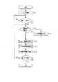
以下、本発明を具体化した一実施形態を図1〜図8に従って説明する。図1は、駐車支援システム1のブロック図である。駐車支援システム1は、駐車支援装置としての駐車支援ユニット2を有している。駐車支援ユニット2は、自車位置演算部10、入力インターフェース(I/F)11、画像入力部12、周辺画像描画手段としての俯瞰変換部13、俯瞰データ記憶部14、周辺画像描画手段、自車画像描画手段としての画像合成部15、駐車枠認識部16、予想軌跡線演算部17、描画切替手段としての画像固定制御部18を備えている。(First embodiment)
Hereinafter, an embodiment embodying the present invention will be described with reference to FIGS. FIG. 1 is a block diagram of the
自車位置演算部10は、車速センサ20及びジャイロ21から車速パルス及び方位検出信号を入力し、基準位置からの移動距離及び移動方向を算出する。画像入力部12は、自車両C(図2参照)の後端に取り付けられたカメラ25を制御して撮影を行う。カメラ25は、車両後方であって、車両後端から所定距離範囲を撮影可能に取り付けられている。画像入力部12は、自車両Cに設けられたニュートラルスタートスイッチ22から、リバースを示すシフトポジション信号を入力すると、カメラ25を制御して撮影を行う。また、自車位置演算部10に基づき、自車両Cの後退中に所定のタイミングで撮影を行い、画
像データGを取得する。The own vehicle
俯瞰変換部13は、画像入力部12から画像データGを取得して、座標変換を行う。具体的には、予め記憶した俯瞰変換テーブルを参照して、画像データGの各画素の座標を、俯瞰変換テーブルによって紐付けられた変換先の座標に変換する。これにより、カメラ視点で撮影された画像データGは、路面に対して鉛直方向上方の位置に設定された視点から路面を鳥瞰した俯瞰データG1に変換される。 The overhead
俯瞰データG1を生成すると、俯瞰変換部13は、俯瞰データ記憶部14に俯瞰データG1を書き込む。このとき、俯瞰変換部13は、予め確保されたメモリ領域のうち、その俯瞰データG1を撮影した車両位置に対応する領域に俯瞰データG1を書き込む。さらに自車両Cが後退すると、その度に異なる領域の路面を描画した俯瞰データG1が生成される。このため、俯瞰変換部13は、異なる領域を描画した各俯瞰データG1を、それぞれ異なる領域に書き込むことにより、俯瞰データG1を合成する。このように書き込んだ俯瞰データG1の数が増えるに従い、車両周辺の路面のデータが俯瞰データ記憶部14に蓄積されていく。 When the overhead data G <b> 1 is generated, the
画像合成部15は、俯瞰データ記憶部14に記憶された俯瞰データG1を読み出し、この俯瞰データG1と、カメラ25から新たに取得した画像データG(以下、現在画像データG2という)とを合成し、図2に示すような合成データG3を生成する。俯瞰データG1の読み出しの際、画像合成部15は、現在のカメラ25の死角に相当する領域の俯瞰データG1を読み出し、この俯瞰データG1と現在画像データG2とを合成する。合成データG3を生成すると、画像合成部15は、表示手段としてのディスプレイ5に合成データG3を出力する。これにより、俯瞰データG1に基づく過去画像31と、現在画像データG2に基づく現在画像32とからなる合成画像33が表示される。合成画像33には、路面に標示された白線や障害物が表示される。 The
また、図2に示すように、画像合成部15は、合成データG3のうち、自車両Cの現在位置に相当する所定位置に、車両画像データ15a(図1参照)を出力し、自車画像35を表示する。本実施形態では、画像表示範囲Rのうち、上方中央の初期位置に自車画像35を表示する。 Further, as shown in FIG. 2, the
駐車枠認識部16は、俯瞰データG1又は現在画像データG2に基づき、公知の処理方法により駐車枠を認識する。例えば、俯瞰データG1又は現在画像データG2に対しエッジ検出を行い、平行な1対のエッジによって囲まれた領域を駐車枠にしてもよい。又は、図示しない記憶部に各地の駐車場マップを格納し、自車位置に対応する駐車場マップを読み出して、その駐車場マップと自車位置とを参照し、車両周辺の駐車枠を検出しても良い。或いは、駐車場マップと、俯瞰データG1又は現在画像データG2を用いてテンプレートマッチングを行い、車両周辺の駐車枠を検出してもよい。又は、俯瞰データG1等に基づき、他車両を認識して、他車両が駐車しているスペース及び他車両の間の空きスペースを駐車枠として認識してもよい。 The parking
また、駐車枠認識部16は、自車両Cが進入する目標駐車枠F1を設定する。例えば、タッチパネル式のディスプレイ5において、ユーザの操作により画面上で駐車枠が指定された場合には、指定された駐車枠を目標駐車枠F1とする。或いは、認識した駐車枠Fのうち、自車両Cの舵角に基づき自車両Cの予想軌跡線に近い駐車枠Fを目標駐車枠F1としてもよい。 Moreover, the parking
予想軌跡線演算部17は、合成画像33上に公知の処理方法により予想軌跡線を描画する。例えば、ステアリングセンサ23からステアリング値を取得し、このステアリング値
を前輪舵角に変換する。また、前輪舵角とホイールベースの長さから旋回半径を算出し、その旋回半径から旋回中心点を特定する。さらに、旋回中心点から各後輪までの距離を各後輪の旋回半径とし、旋回中心点を中心に各後輪の予想軌跡線の代表点を演算する。代表点の座標を演算すると、予想軌跡線演算部17は、各代表点の間を曲線又は直線で描画した予想軌跡線36を合成画像33上に描画する。The predicted trajectory line calculation unit 17 draws an expected trajectory line on the
画像固定制御部18は、目標駐車枠F1のディスプレイ5の表示状態に基づき、所定のタイミングで目標駐車枠F1を所定の駐車枠描画位置に固定した状態で合成画像33を表示する。詳述すると、まず、画像固定制御部18は、駐車枠認識部16に基づき、目標駐車枠F1の4隅を示す端点P1〜P4の座標を取得する。さらに、自車両Cの後退に伴い、各端点P1〜P4が、ディスプレイ5の描画範囲を示す画像表示範囲Rに全て含まれたか否かを判断する。尚、本実施形態では、各端点P1〜P4が画像表示範囲Rに含まれるか否かを判断するようにしたが、要は目標駐車枠F1の全域が画像表示範囲Rに含まれたか否かを判断できれば良く、目標駐車枠F1を示すエッジEGが全て画像表示範囲Rに含まれるか否かを判断するようにしても良い。 The image fixing
図3に示すように、画像表示範囲Rに、各端点P1〜P4が全て含まれたと判断すると、合成データG3を用い、画像座標系(x、y)内で、目標駐車枠F1の進入口である前端の中心点Paの座標(x1,y1)を取得する。また、目標駐車枠F1の後端の中心点Pbの座標(x2,y2)とを算出する。また、各中心点Pa,Pbを通る目標駐車枠F1の中心線LFと、自車両C(車両画像)の中心線LCとがなす相対角度θを算出する。この相対角度θを算出する際は、数式(1)を用いることができる。但し、「y2―y1=0」である場合には、Δθは、180°(x1<x2)、又は−180°(x1>x2)とする。As shown in FIG. 3, when it is determined that the end points P1 to P4 are all included in the image display range R, the entry point of the target parking frame F1 is used in the image coordinate system (x, y) using the composite data G3. The coordinates (x1 , y1 ) of the front end center point Pa are acquired. Further, the coordinates (x2 , y2 ) of the center point Pb at the rear end of the target parking frame F1 are calculated. Further, a relative angle θ formed by the center line LF of the target parking frame F1 passing through the center points Pa and Pb and the center line LC of the host vehicle C (vehicle image) is calculated. Formula (1) can be used to calculate the relative angle θ. However, when “y2 −y1 = 0”, Δθ is 180 ° (x1 <x2 ) or −180 ° (x1 > x2 ).

自車両Cに対する目標駐車枠F1の相対角度θを算出すると、目標駐車枠F1を画像表示範囲Rの下端中央に配置するために、車両画像データ15a、予想軌跡線36及び合成データG3を平行移動及び回転移動する。即ち、駐車枠後端の中心点Pbを、画像表示範囲Rの原点に移動する平行移動を行う。さらに、原点(0,0)に位置付けられた中心点Pbを中心に、合成データG3を相対角度θだけ回転移動する。さらに、中心点Pbを画像表示範囲Rの下端中央に移動させるための平行移動を再び行う。この一連の画像処理は、数式(2)を用いて変換することができる。尚、xmax、ymaxは、画像表示範囲Rのx座標及びy座標の最大値である。また、dx=−x2、dy=−y2である。When the relative angle θ of the target parking frame F1 with respect to the host vehicle C is calculated, the
次に、本実施形態の処理手順について、図5〜図7に従って説明する。図5に示すように、駐車支援を開始する際に、駐車支援ユニット2は、システムを初期化し(ステップS1)、開始トリガの有無を判断する(ステップS2)。本実施形態では、開始トリガは、自車両Cのシフトレバーの切替によって生じる電気的信号であるシフトポジション信号であって、リバースを示す信号とする。 Next, the processing procedure of this embodiment is demonstrated according to FIGS. As shown in FIG. 5, when parking assistance is started, the
開始トリガを入力したと判断すると(ステップS2においてYES)、駐車枠認識部16は、目標駐車枠F1が設定済みであるか否かを判断する(ステップS3)。開始トリガを入力した直後は目標駐車枠F1が設定されていないと判断し(ステップS3においてNO)、目標駐車枠F1を設定する(ステップS4)。このとき、上記したように、ユーザの操作により画面上で駐車枠が指定された場合に、指定された駐車枠を目標駐車枠F1とするか、或いは予想軌跡線36を演算し、認識した駐車枠Fのうち、予想軌跡線36に近い駐車枠Fを目標駐車枠F1とする。 If it is determined that the start trigger is input (YES in step S2), the parking
ユーザの入力操作により目標駐車枠F1を設定する場合には、例えば画像入力部12によりカメラ25から画像データGを入力し、画像合成部15により画像データGに基づく画像を表示する。このとき画像データGは、俯瞰変換部13により俯瞰変換してもよい。さらに、ユーザにより画像の所定の位置を指定するタッチパネル操作が行われると、ディスプレイ5の検出部(図示略)は指の接触位置を検出し、接触位置を駐車枠認識部16に出力する。駐車枠認識部16は、出力した画像データGと接触位置とを参照して、ユーザによって指定された位置を目標駐車枠F1として設定する。予想軌跡線36に基づき目標駐車枠F1を設定する際には、例えば駐車枠認識部16がカメラ25から画像データGを取得し、この画像データGに対してエッジ検出を行い、駐車枠を区画する白線を認識する。複数の駐車枠が認識された場合には、予想軌跡線演算部17により現在の舵角に応じた予想軌跡線36を演算し、この予想軌跡線36に近い駐車枠を目標駐車枠F1として設定する。 When the target parking frame F1 is set by a user input operation, for example, the image data G is input from the
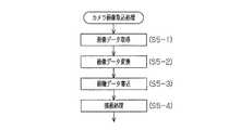
目標駐車枠を設定すると、画像入力部12、俯瞰変換部13及び画像合成部15によりカメラ画像取込処理を行う(ステップS5)。このカメラ画像取込処理について図6に従って説明する。図6に示すように、画像入力部12は、カメラ25を制御して車両後方を撮影した画像データGを取得する(ステップS5−1)。 When the target parking frame is set, camera image capture processing is performed by the
俯瞰変換部13は、上記したように俯瞰変換テーブルを用い、取得した画像データGの座標変換を行う(ステップS5−2)。これにより、路面に対して鉛直方向上方の視点から路面を鳥瞰した俯瞰データG1が生成される。 The
また、俯瞰変換部13は、生成した俯瞰データG1を俯瞰データ記憶部14に書き込む(ステップS5−3)。このとき、上記したように、俯瞰データ記憶部14のメモリ領域のうち、その俯瞰データG1を撮影した位置に対応する領域に俯瞰データG1を書き込こむ。 Moreover, the overhead
さらに、画像合成部15は、俯瞰データG1を用いて描画処理を行う(ステップS5−4)。このとき、上記したように、例えば、俯瞰データ記憶部14に書き込まれた俯瞰データG1のうち、現在のカメラ25の死角である所定領域を抽出する。また、この抽出データと、現在画像データG2とを合成して、合成データG3を生成する。また、画像表示範囲Rのうち、上記初期描画位置に、車両画像データ15aに基づく自車画像35を描画する。その結果、図8(a)に示すように、合成画像33がディスプレイ5の画面に表示される。 Furthermore, the
このようにカメラ画像取込処理を終了すると、図5に示すように、予想軌跡線演算部17が、上記したように予想軌跡線描画処理を行う(ステップS6)。その結果、図8(a)に示すように、予想軌跡線36が合成画像33に重畳される。 When the camera image capturing process is completed in this way, as shown in FIG. 5, the predicted trajectory line calculation unit 17 performs the predicted trajectory line drawing process as described above (step S6). As a result, the expected
さらに、画像固定制御部18は、画像固定処理を行う(ステップS7)。この画像固定処理について、図7に従って説明する。画像固定制御部18は、駐車枠認識部16に基づき、目標駐車枠F1が画像表示範囲R内に含まれているか否かを判断する(ステップS7−1)。このとき、例えば駐車枠認識部16は、ステップS4で設定された目標駐車枠F1の端点P1〜P4の座標を取得し、自車両Cの移動に伴い、目標駐車枠F1の4隅の端点P1〜P4が画像表示範囲R内に含まれているか否かを判断する。又は、合成データG3と駐車場マップとを比較してマッチングを行い、画像表示範囲R内に上記した駐車場マップと同じ目標駐車枠を検出した場合に、目標駐車枠F1が画像表示範囲R内に含まれると判断するようにしてもよい。 Further, the image fixing
目標駐車枠F1が画像表示範囲R内に含まれると判断すると(ステップS7−1においてYES)、上記したように画像固定制御部18は、画像座標系(x、y)において、目標駐車枠F1の位置と、目標駐車枠F1と自車両Cとがなす相対角度θとを算出する(ステップS7−2)。このとき、上記したように、目標駐車枠F1の位置として、目標駐車枠F1の後端の中心点Pbの座標と前端の中心点Paの座標とを取得する(図3参照)。さらに、各中心点Pa,Pbを通る目標駐車枠F1の中心線LFと、自車両C(車両画像)の中心線LCとがなす相対角度θを算出する。 If it is determined that the target parking frame F1 is included in the image display range R (YES in step S7-1), as described above, the image fixing
さらに画像固定制御部18は、目標駐車枠F1を中心として、平行移動及び回転移動を行う(ステップS7−3)。このとき、上記したように、目標駐車枠F1の下端の中心点Pbを原点(0,0)に移動する平行移動を車両画像データ15a、予想軌跡線36及び合成データG3に対して行う。また、車両画像データ15a、予想軌跡線36及び合成データG3を原点に位置付けられた中心点Pbを中心に相対角度θだけ回転移動する。さらに、原点(0,0)にある中心点Pbを、画像表示範囲Rの下端中央に配置する平行移動を行う。 Furthermore, the image fixing
平行移動及び回転移動を行うと、平行移動及び回転移動した車両画像データ15a、予想軌跡線36及び合成データG3のうち、ディスプレイ5の画像表示範囲Rに含まれる画像を描画する(ステップS7−4)。これにより、図4に示すように、画像表示範囲R外となった合成データG3は表示されない。また、図4中斜線で示す箇所のように、画像表示範囲Rのうち、合成データG3が書き込まれない領域は、非表示としても良いし、俯瞰データG1及び現在画像データG2のうち対応するデータを新たに書き込んでもよい。これにより、図8(b)に示すように、ディスプレイ5には、目標駐車枠F1が画像表示範
囲Rのうち駐車枠描画位置に表示された駐車支援画面40が表示される。When the parallel movement and the rotational movement are performed, an image included in the image display range R of the
画像固定処理を終了すると、駐車支援ユニット2は終了トリガの有無を判断する(ステップS8)。終了トリガは、リバース以外のシフトポジションを示すシフトポジション信号である。自車両Cが後退中である場合、終了トリガを入力しないと判断して(ステップS8においてNO)、ステップS3に戻り、目標駐車枠F1が設定済みであるか否かを判断する(ステップS3)。このとき、目標駐車枠F1は既に設定済みであるため(ステップS3においてYES)、ステップS5に進み、上記した処理を繰り返す。 When the image fixing process is completed, the
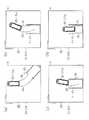
画像固定制御部18は、画像表示範囲R内に目標駐車枠F1が全て含まれている間、目標駐車枠F1を駐車枠描画位置に固定した状態で、合成画像33を固定する。このため、自車両Cが図8(b)に示す位置から、図8(c)に示す駐車支援画面40のように、目標駐車枠F1により近い位置に到達しても、自車画像35のみが移動し、合成画像33は描画範囲が固定された状態で表示されている。このとき、合成画像33の少なくとも一部は、最新の現在画像データG2を用いて更新されているため、車両後方の所定領域に移動障害物が進入すると、その移動障害物が合成画像33に表示される。 The image fixing
さらに図8(d)に示すように、自車両Cが目標駐車枠F1に進入しても、合成画像33を固定した状態とする。自車両Cが後方へ直進すると、あたかも路面標示された目標駐車枠F1に自車両Cに進入していく様子を鳥瞰しているようにみえるので、ドライバーは違和感を感じることなく、自車両Cの位置や、白線とのずれを把握することができる。 Further, as shown in FIG. 8D, even if the host vehicle C enters the target parking frame F1, the
第1実施形態によれば、以下のような効果を得ることができる。
(1)第1実施形態では、自車両Cが目標駐車枠F1に接近した際に、目標駐車枠F1を所定の駐車枠描画位置に固定した状態で合成画像33が表示される。このため、自車両Cの後退に伴い、固定表示された目標駐車枠F1に自車画像35が移動していくので、ドライバーが違和感を感じず、自車両Cと目標駐車枠F1との相対位置を直ちに理解できる画面を表示することができる。According to the first embodiment, the following effects can be obtained.
(1) In the first embodiment, when the host vehicle C approaches the target parking frame F1, the
(2)第1実施形態では、目標駐車枠F1の全領域が画像表示範囲Rに含まれた場合に、目標駐車枠F1を駐車枠描画位置に固定して描画する。即ち、自車両Cが目標駐車枠F1に接近する前から固定するのではなく、自車両Cが目標駐車枠F1に接近した際に、目標駐車枠F1の描画位置を固定できる。このため、目標駐車枠F1と自車両Cとの相対位置を把握し、ステアリングの微調整をする際に、合成画像33が固定されるので、的確なタイミングで画像を固定できる。 (2) In the first embodiment, when the entire area of the target parking frame F1 is included in the image display range R, the target parking frame F1 is fixed and drawn at the parking frame drawing position. That is, the drawing position of the target parking frame F1 can be fixed when the own vehicle C approaches the target parking frame F1, instead of fixing before the own vehicle C approaches the target parking frame F1. For this reason, since the
(3)第1実施形態では、駐車枠描画位置を、画像表示範囲Rのうち下方中央にするようにした。このため、画面内で自車画像35が移動可能なスペースを確保し、自車両Cが目標駐車枠F1に向かって後退する様子を見やすい画面を表示することができる。 (3) In the first embodiment, the parking frame drawing position is set at the lower center of the image display range R. For this reason, the space which the
(第2実施形態)
次に、本発明を具体化した第2の実施形態を図9に従って説明する。尚、第2の実施形態は、第1の実施形態の画像固定のタイミングを変更したのみの構成であるため、同様の部分についてはその詳細な説明を省略する。(Second Embodiment)
Next, a second embodiment of the present invention will be described with reference to FIG. Since the second embodiment has a configuration in which the image fixing timing of the first embodiment is changed, detailed description of the same parts is omitted.
第2実施形態では、まず、第1実施形態と同様に、画像固定制御部18は、目標駐車枠F1が画像表示範囲R内に含まれているか否かを判断する。目標駐車枠F1の全域が画像表示範囲Rに含まれたと判断した場合、目標駐車枠F1の位置と相対角度θとを上記したように算出し、相対角度θが0°付近であるか否かを判断する。さらに相対角度θが0°付近になったと判断した場合に、目標駐車枠F1の位置を固定して合成画像33を表示す
る。例えば目標駐車枠F1のy軸に対する相対角度θの絶対値が5°以内である場合に、相対角度θが0°付近になったと判断する。In the second embodiment, first, similarly to the first embodiment, the image fixing
図9(a)及び図9(b)に示すように、自車両Cが目標駐車枠F1に向かって旋回している場合には、自車画像35を画像表示範囲Rの上方中央の初期描画位置に表示し、車両位置から所定距離範囲内に相当する合成画像33を表示する。これにより、目標駐車枠F1は画像表示範囲R内に固定されず、合成画像33は自車両Cの後退に伴い変化する。 As shown in FIGS. 9A and 9B, when the host vehicle C is turning toward the target parking frame F1, an initial drawing of the
図9(c)に示すように、自車両Cが目標駐車枠F1に対してほぼ平行になると、画像固定制御部18は、その時点の目標駐車枠F1の位置を固定した状態で合成画像33を表示する。図9(c)では、目標駐車枠F1が、画像表示範囲Rのうち、略中央に固定されている。 As shown in FIG. 9C, when the host vehicle C is substantially parallel to the target parking frame F1, the image fixing
そして、さらに自車両Cが後方に直進した場合には、目標駐車枠F1は最初に固定された位置(図9(c)では略中央)で表示され、固定された目標駐車枠F1に対して自車画像35が動く。このとき、自車両Cに対する目標駐車枠F1の相対角度θは、「0°」であるため、回転変換は行わない。 When the host vehicle C further travels straight back, the target parking frame F1 is displayed at the first fixed position (substantially the center in FIG. 9C), and is relative to the fixed target parking frame F1. The
従って、第2の実施形態によれば、第1の実施形態に記載の効果に加えて以下の効果を得ることができる。
(1)第2の実施形態では、目標駐車枠F1が自車両Cに平行になった場合に、目標駐車枠F1を下方中央の位置に固定して描画する。このため、目標駐車枠F1に対して自車両Cが後退するような画像が表示できるので、的確なタイミングで、違和感のない駐車支援画面40を表示できる。Therefore, according to the second embodiment, in addition to the effects described in the first embodiment, the following effects can be obtained.
(1) In the second embodiment, when the target parking frame F1 is parallel to the host vehicle C, the target parking frame F1 is fixed and drawn at the lower center position. For this reason, since the image which the own vehicle C retreats with respect to the target parking frame F1 can be displayed, the
尚、本実施形態は以下のように変更してもよい。
・第1実施形態では、目標駐車枠F1が画像表示範囲R内に含まれた際に、自車画像35を画像表示範囲Rの下方中央に配置した状態で合成画像33を表示したが、これ以外の位置でもよい。例えば、画像表示範囲Rの中央でも良い。In addition, you may change this embodiment as follows.
In the first embodiment, when the target parking frame F1 is included in the image display range R, the
・上記実施形態では、車両周辺を俯瞰した合成画像33を駐車支援画面40に表示したが、画像データGに基づくモニタ画像を駐車支援画面40として表示してもよい。このとき、画像データGには、通常、車体の一部が撮影されているため、この車体画像を自車画像とする。そして、カメラ25の撮影範囲に目標駐車枠F1の少なくとも一部が含まれたとき等のタイミングで、目標駐車枠F1の表示位置を固定した合成画像を表示するようにしてもよい。 In the above embodiment, the
・上記実施形態では、画像データGに基づく写真画像上に自車画像35を描画したが、予め記憶した駐車場マップに基づく画像上に自車画像35を描画してもよい。
・上記実施形態では、合成画像33のうち、俯瞰データG1に基づく過去画像31を省略しても良い。In the above embodiment, the
In the above embodiment, the
・上記実施形態では、目標駐車枠F1が画像表示範囲Rに含まれたとき、目標駐車枠F1が自車両Cに対して平行になったときをトリガとして、合成画像33を固定するようにした。これ以外に、予め設定した目標駐車枠F1でなく、いずれかの駐車枠Fが画像表示範囲Rに含まれたとき、いずれかの駐車枠Fが自車両Cに対して平行になったときをトリガとしてもよい。 In the above embodiment, when the target parking frame F1 is included in the image display range R, the
1…駐車支援システム、2…駐車支援装置としての駐車支援ユニット、5…表示手段としてのディスプレイ、13…周辺画像描画手段としての俯瞰変換部、15…周辺画像描画手段、自車画像描画手段としての画像合成部、18…描画切替手段としての画像固定制御部、33…車両周辺画像としての合成画像、35…自車画像、C…車両、F…駐車枠、R…画像表示範囲。 DESCRIPTION OF
Claims (5)
Translated fromJapanese車両周辺画像を前記表示手段に出力し、前記車両周辺画像のうち、前記車両の現在位置に相当する位置に自車画像を描画するとともに、
前記車両が駐車枠に接近した際に、該駐車枠を所定位置に固定して前記車両周辺画像を描画し、前記車両の後退に伴い、前記自車画像を前記車両周辺画像上で移動することを特徴とする駐車支援方法。In the parking support method for displaying the image around the vehicle on the display means,
A vehicle periphery image is output to the display means, and the vehicle image is drawn at a position corresponding to the current position of the vehicle among the vehicle periphery images,
When the vehicle approaches the parking frame, the parking frame is fixed at a predetermined position, the vehicle surrounding image is drawn, and the host vehicle image is moved on the vehicle surrounding image as the vehicle moves backward. A parking assistance method characterized by the above.
車両周辺画像を前記表示手段に出力する周辺画像描画手段と、
前記車両周辺画像のうち、前記車両の現在位置に相当する位置に自車画像を描画する自車画像描画手段と、
前記車両が駐車枠に接近した際に、該駐車枠を所定位置に固定して前記車両周辺画像を描画し、前記車両の後退に伴い、前記自車画像を前記車両周辺画像上で移動する描画切替手段と
を備えたことを特徴とする駐車支援装置。In the parking assist device that displays the image around the vehicle on the display means,
Peripheral image drawing means for outputting a vehicle peripheral image to the display means;
A vehicle image drawing means for drawing a vehicle image at a position corresponding to the current position of the vehicle among the vehicle peripheral images;
When the vehicle approaches the parking frame, the parking frame is fixed at a predetermined position to draw the vehicle surrounding image, and the vehicle image is moved on the vehicle surrounding image as the vehicle moves backward A parking assistance device comprising switching means.
前記描画切替手段は、
前記駐車枠の全領域が前記表示手段の画像表示範囲に含まれた場合に、該駐車枠を所定位置に固定して描画した前記車両周辺画像を描画することを特徴とする駐車支援装置。In the parking assistance device according to claim 2,
The drawing switching means includes
The parking assistance device, wherein when the entire area of the parking frame is included in the image display range of the display means, the vehicle periphery image drawn with the parking frame fixed at a predetermined position is drawn.
前記描画切替手段は、
前記車両周辺画像に表示された前記駐車枠が、前記車両に対して平行になった場合に、該駐車枠を所定位置に固定して描画した前記車両周辺画像を描画することを特徴とする駐車支援装置。In the parking assistance device according to claim 2 or 3,
The drawing switching means includes
When the parking frame displayed in the vehicle periphery image is parallel to the vehicle, the parking region is drawn with the parking frame fixed and drawn at a predetermined position. Support device.
前記描画切替手段は、前記駐車枠の表示位置を、画像表示範囲のうち下方中央にした状態で前記車両周辺画像を表示することを特徴とする駐車支援装置。In the parking assistance device according to any one of claims 2 to 4,
The said drawing switching means displays the said vehicle periphery image in the state which made the display position of the said parking frame the lower center of the image display range, The parking assistance apparatus characterized by the above-mentioned.
Priority Applications (1)
| Application Number | Priority Date | Filing Date | Title |
|---|---|---|---|
| JP2007053146AJP2008213647A (en) | 2007-03-02 | 2007-03-02 | Parking assist method and parking assist system |
Applications Claiming Priority (1)
| Application Number | Priority Date | Filing Date | Title |
|---|---|---|---|
| JP2007053146AJP2008213647A (en) | 2007-03-02 | 2007-03-02 | Parking assist method and parking assist system |
Publications (1)
| Publication Number | Publication Date |
|---|---|
| JP2008213647Atrue JP2008213647A (en) | 2008-09-18 |
Family
ID=39834202
Family Applications (1)
| Application Number | Title | Priority Date | Filing Date |
|---|---|---|---|
| JP2007053146APendingJP2008213647A (en) | 2007-03-02 | 2007-03-02 | Parking assist method and parking assist system |
Country Status (1)
| Country | Link |
|---|---|
| JP (1) | JP2008213647A (en) |
Cited By (9)
| Publication number | Priority date | Publication date | Assignee | Title |
|---|---|---|---|---|
| JP2011006005A (en)* | 2009-06-26 | 2011-01-13 | Kyocera Corp | Device and method for supporting driving in parking |
| WO2013002037A1 (en)* | 2011-06-27 | 2013-01-03 | クラリオン株式会社 | Parking assistance device |
| JP2013049425A (en)* | 2012-11-27 | 2013-03-14 | Nissan Motor Co Ltd | Vehicle acceleration suppression device and vehicle acceleration suppression method |
| JP2013228832A (en)* | 2012-04-25 | 2013-11-07 | Sony Corp | Travel support image generation device, travel support image generation method, in-vehicle camera, and apparatus steering support image generation device |
| KR102180193B1 (en)* | 2019-05-30 | 2020-11-18 | 한양대학교 산학협력단 | Method and apparatus for parking space pose detection using parking stripe template matching |
| CN112016381A (en)* | 2019-05-30 | 2020-12-01 | 歌乐株式会社 | Image processing apparatus and image processing method |
| CN116691703A (en)* | 2023-06-09 | 2023-09-05 | 惠州市德赛西威汽车电子股份有限公司 | Method, device, vehicle and storage medium for determining heading angle of inclined train |
| WO2024188404A1 (en)* | 2023-03-14 | 2024-09-19 | Continental Autonomous Mobility Germany GmbH | Method for generating a surrounding view of a vehicle , image capture device and vehicle |
| JP7576066B2 (en) | 2022-03-14 | 2024-10-30 | 本田技研工業株式会社 | Control device, control method, and control program |
Citations (2)
| Publication number | Priority date | Publication date | Assignee | Title |
|---|---|---|---|---|
| JPH0848198A (en)* | 1994-08-08 | 1996-02-20 | Nissan Motor Co Ltd | Surrounding monitor device for vehicles |
| JP2005343417A (en)* | 2004-06-07 | 2005-12-15 | Auto Network Gijutsu Kenkyusho:Kk | Parking assist device |
- 2007
- 2007-03-02JPJP2007053146Apatent/JP2008213647A/enactivePending
Patent Citations (2)
| Publication number | Priority date | Publication date | Assignee | Title |
|---|---|---|---|---|
| JPH0848198A (en)* | 1994-08-08 | 1996-02-20 | Nissan Motor Co Ltd | Surrounding monitor device for vehicles |
| JP2005343417A (en)* | 2004-06-07 | 2005-12-15 | Auto Network Gijutsu Kenkyusho:Kk | Parking assist device |
Cited By (16)
| Publication number | Priority date | Publication date | Assignee | Title |
|---|---|---|---|---|
| JP2011006005A (en)* | 2009-06-26 | 2011-01-13 | Kyocera Corp | Device and method for supporting driving in parking |
| WO2013002037A1 (en)* | 2011-06-27 | 2013-01-03 | クラリオン株式会社 | Parking assistance device |
| JP2013006548A (en)* | 2011-06-27 | 2013-01-10 | Clarion Co Ltd | Parking assist device |
| CN103596812A (en)* | 2011-06-27 | 2014-02-19 | 歌乐株式会社 | Parking assistance device |
| US11628882B2 (en) | 2012-04-25 | 2023-04-18 | Sony Group Corporation | Cruise-assist image generation device, cruise-assist image generation method, in-vehicle camera and equipment-control assist image generation device |
| JP2013228832A (en)* | 2012-04-25 | 2013-11-07 | Sony Corp | Travel support image generation device, travel support image generation method, in-vehicle camera, and apparatus steering support image generation device |
| US9533709B2 (en) | 2012-04-25 | 2017-01-03 | Sony Corporation | Cruise-assist image generation device, cruise-assist image generation method, in-vehicle camera and equipment-control assist image generation device |
| US10696328B2 (en) | 2012-04-25 | 2020-06-30 | Sony Corporation | Cruise-assist image generation device, cruise-assist image generation method, in-vehicle camera and equipment-control assist image generation device |
| JP2013049425A (en)* | 2012-11-27 | 2013-03-14 | Nissan Motor Co Ltd | Vehicle acceleration suppression device and vehicle acceleration suppression method |
| KR102180193B1 (en)* | 2019-05-30 | 2020-11-18 | 한양대학교 산학협력단 | Method and apparatus for parking space pose detection using parking stripe template matching |
| CN112016381A (en)* | 2019-05-30 | 2020-12-01 | 歌乐株式会社 | Image processing apparatus and image processing method |
| CN112016381B (en)* | 2019-05-30 | 2024-04-02 | 歌乐株式会社 | Image processing apparatus and image processing method |
| JP7576066B2 (en) | 2022-03-14 | 2024-10-30 | 本田技研工業株式会社 | Control device, control method, and control program |
| WO2024188404A1 (en)* | 2023-03-14 | 2024-09-19 | Continental Autonomous Mobility Germany GmbH | Method for generating a surrounding view of a vehicle , image capture device and vehicle |
| CN116691703A (en)* | 2023-06-09 | 2023-09-05 | 惠州市德赛西威汽车电子股份有限公司 | Method, device, vehicle and storage medium for determining heading angle of inclined train |
| WO2024250641A1 (en)* | 2023-06-09 | 2024-12-12 | 惠州市德赛西威汽车电子股份有限公司 | Method and apparatus for determining heading angle of angled parking space, vehicle, and storage medium |
Similar Documents
| Publication | Publication Date | Title |
|---|---|---|
| CA3069114C (en) | Parking assistance method and parking assistance device | |
| KR101375944B1 (en) | Parking assistance system | |
| JP5003946B2 (en) | Parking assistance device | |
| JP2008213647A (en) | Parking assist method and parking assist system | |
| WO2016002163A1 (en) | Image display device and image display method | |
| EP2963922A1 (en) | Program and device for controlling vehicle | |
| JP5471141B2 (en) | Parking assistance device and parking assistance method | |
| JP2001163132A (en) | Image converting device for device for monitoring back of vehicle | |
| JP2005112004A (en) | Vehicle retraction support apparatus and method | |
| JP5446139B2 (en) | Parking assistance device and parking assistance method | |
| CN114179725B (en) | Display device for vehicle | |
| JP2009083680A (en) | Parking assistance device and parking assistance method | |
| JP2004254219A (en) | Vehicular surrounding image processing apparatus and program, and recording medium | |
| JP2008279875A (en) | Parking support device | |
| JP2008213791A (en) | Parking assist method and parking assist system | |
| JP2012076551A (en) | Parking support device, parking support method, and parking support system | |
| JP5273068B2 (en) | Vehicle periphery monitoring device | |
| JP2008148114A (en) | Drive assisting device | |
| JP2010154304A (en) | Mobile camera system and driving method | |
| JP4857159B2 (en) | Vehicle driving support device | |
| JP2007168560A (en) | Parking support apparatus | |
| JP2017149398A (en) | Parking support device and parking support method | |
| KR20160107529A (en) | Apparatus and method for parking assist animated a car image | |
| JP2011118485A (en) | U-turn supporting device and method | |
| JP2009220592A (en) | On-vehicle parallel parking assistant device and program for on-vehicle parallel parking assistant device |
Legal Events
| Date | Code | Title | Description |
|---|---|---|---|
| A621 | Written request for application examination | Free format text:JAPANESE INTERMEDIATE CODE: A621 Effective date:20090714 | |
| A521 | Written amendment | Free format text:JAPANESE INTERMEDIATE CODE: A523 Effective date:20100712 | |
| A977 | Report on retrieval | Free format text:JAPANESE INTERMEDIATE CODE: A971007 Effective date:20110530 | |
| A131 | Notification of reasons for refusal | Free format text:JAPANESE INTERMEDIATE CODE: A131 Effective date:20110607 | |
| A02 | Decision of refusal | Free format text:JAPANESE INTERMEDIATE CODE: A02 Effective date:20111108 |