JP2008213147A - Liquid supply apparatus and image recording apparatus - Google Patents
Liquid supply apparatus and image recording apparatusDownload PDFInfo
- Publication number
- JP2008213147A JP2008213147AJP2007049264AJP2007049264AJP2008213147AJP 2008213147 AJP2008213147 AJP 2008213147AJP 2007049264 AJP2007049264 AJP 2007049264AJP 2007049264 AJP2007049264 AJP 2007049264AJP 2008213147 AJP2008213147 AJP 2008213147A
- Authority
- JP
- Japan
- Prior art keywords
- liquid supply
- liquid
- groove
- ink
- posture
- Prior art date
- Legal status (The legal status is an assumption and is not a legal conclusion. Google has not performed a legal analysis and makes no representation as to the accuracy of the status listed.)
- Pending
Links
- 239000007788liquidSubstances0.000titleclaimsabstractdescription156
- 230000007246mechanismEffects0.000claimsabstractdescription22
- 238000000034methodMethods0.000claimsdescription11
- 230000008569processEffects0.000claimsdescription10
- 239000000976inkSubstances0.000description256
- 230000036544postureEffects0.000description51
- 238000003780insertionMethods0.000description38
- 230000037431insertionEffects0.000description38
- 238000004891communicationMethods0.000description9
- 238000010586diagramMethods0.000description8
- 238000000926separation methodMethods0.000description6
- 230000008901benefitEffects0.000description4
- 239000003086colorantSubstances0.000description3
- 238000000605extractionMethods0.000description3
- 230000002093peripheral effectEffects0.000description3
- 230000033228biological regulationEffects0.000description2
- 239000000446fuelSubstances0.000description2
- 239000000203mixtureSubstances0.000description2
- 239000011347resinSubstances0.000description2
- 229920005989resinPolymers0.000description2
- 230000008859changeEffects0.000description1
- 230000008878couplingEffects0.000description1
- 238000010168coupling processMethods0.000description1
- 238000005859coupling reactionMethods0.000description1
- 230000007423decreaseEffects0.000description1
- 238000007599dischargingMethods0.000description1
- 230000005489elastic deformationEffects0.000description1
- 239000004973liquid crystal related substanceSubstances0.000description1
- 230000001105regulatory effectEffects0.000description1
- 230000004044responseEffects0.000description1
- 238000009751slip formingMethods0.000description1
- 238000011144upstream manufacturingMethods0.000description1
Images


Landscapes
- Ink Jet (AREA)
Abstract
Translated fromJapaneseDescription
Translated fromJapanese本発明は、液体容器とケースとの連結を維持するロック機構を有する液体供給装置、及び当該液体供給装置を備えた画像記録装置に関するものである。 The present invention relates to a liquid supply apparatus having a lock mechanism that maintains the connection between a liquid container and a case, and an image recording apparatus including the liquid supply apparatus.
画像記録装置の一例として、インクジェットプリンタが知られている。インクジェットプリンタは、記録ヘッドから微小なインク滴を選択的に吐出して、記録用紙に画像記録を行う。記録ヘッドは、インク容器からインクの供給を受ける。インク容器は、インク残量が少なくなると、新たなインク容器に交換可能に構成されている。このような交換可能なインク容器は、一般に、インクカートリッジと称される。 As an example of an image recording apparatus, an ink jet printer is known. An ink jet printer selectively ejects minute ink droplets from a recording head to record an image on a recording sheet. The recording head is supplied with ink from the ink container. The ink container is configured to be replaceable with a new ink container when the remaining amount of ink decreases. Such replaceable ink containers are generally referred to as ink cartridges.
インクカートリッジの交換をユーザが行う。インクカートリッジの交換において、交換されたインクカートリッジが、インクジェットプリンタのジョイント部に確実に連結される必要がある。このような連結を簡易な操作で行う手段として、ワンプッシュ型固定部材を採用したインクカートリッジが提案されている(例えば、特許文献1及び特許文献2参照)。 The user replaces the ink cartridge. In replacing the ink cartridge, the replaced ink cartridge needs to be securely connected to the joint portion of the ink jet printer. As means for performing such a connection with a simple operation, an ink cartridge employing a one-push type fixing member has been proposed (see, for example, Patent Document 1 and Patent Document 2).
特許文献1及び特許文献2において、ワンプッシュ型固定部材は、インクカートリッジにおける液体供給口と異なる位置に設けられている。インクカートリッジが交換される際には、液体供給口にインクニードルなどが挿抜されるので、その挿抜方向に対してインクカートリッジをスライドさせる構成が採用される。また、液体供給口は、公知のバルブによって開閉され、バルブの開閉動作がバネの弾性変形によってなされる。つまり、インクニードルが液体供給口に挿入されることによってバルブが開放される。この状態で、インクカートリッジは、バルブのバネ付勢力を受ける。 In Patent Document 1 and Patent Document 2, the one-push type fixing member is provided at a position different from the liquid supply port in the ink cartridge. When the ink cartridge is replaced, an ink needle or the like is inserted into or removed from the liquid supply port, and thus a configuration in which the ink cartridge is slid in the insertion / extraction direction is employed. The liquid supply port is opened and closed by a known valve, and the opening and closing operation of the valve is performed by elastic deformation of the spring. That is, the valve is opened by inserting the ink needle into the liquid supply port. In this state, the ink cartridge receives a spring biasing force of the valve.
ワンプッシュ型固定部材は、液体供給口と異なる位置において、ケースと協働してインクカートリッジをロックしてジョイントを維持する。前述されたバネ付勢力とロックとの関係によって、インクカートリッジに回転モーメントが生じる。つまり、バネ付勢力がインクニードルが液体供給口から挿抜される方向へ作用するのに対して、ロックする力は、液体供給口と別の位置において当該方向と直交する方向へ作用するので、ロック位置を中心とした回転モーメントがインクカートリッジに生じる。 The one-push type fixing member maintains the joint by locking the ink cartridge in cooperation with the case at a position different from the liquid supply port. A rotational moment is generated in the ink cartridge due to the relationship between the spring biasing force and the lock described above. That is, while the spring biasing force acts in the direction in which the ink needle is inserted / removed from the liquid supply port, the locking force acts in a direction perpendicular to the direction at a position different from the liquid supply port. A rotational moment about the position is generated in the ink cartridge.
前述された回転モーメントによって、インクカートリッジを交換する際にこじれが生じて、円滑なインクカートリッジのスライドが阻害される。また、液体供給口に対するインクニードルの挿抜にもこじれが生じて、インク漏れが生じるおそれがある。さらに、前述された回転モーメントは、インクカートリッジがロックされている際にも生じるので、インク供給口に対してインクニードルがこじれてジョイントが不完全となり、その結果、インク漏れが生じるおそれがある。 The rotational moment described above causes twisting when the ink cartridge is replaced, and smooth sliding of the ink cartridge is hindered. Further, the ink needle may be inserted into and removed from the liquid supply port, which may cause ink leakage. Furthermore, since the above-described rotational moment is generated even when the ink cartridge is locked, the ink needle is twisted with respect to the ink supply port and the joint becomes incomplete, and as a result, ink leakage may occur.
ところで、フルカラー印刷が可能なインクジェットプリンタでは、シアン・マゼンタ・イエロー・ブラックのような複数色のインクが用いられる。これらインクは、各インク色毎にインクカートリッジに充填されている。したがって、各インクカートリッジがそれぞれ装着される各ケースは、指定された色のインクカートリッジが装着されるべく、割り当てが決められている。 By the way, in an ink jet printer capable of full color printing, inks of a plurality of colors such as cyan, magenta, yellow, and black are used. These inks are filled in the ink cartridge for each ink color. Accordingly, each case in which each ink cartridge is mounted is assigned so that an ink cartridge of a designated color is mounted.
インクカートリッジの交換は、ユーザが行う。複数色のインクが用いられるインクジェットプリンタでは、割り当てに応じた適切なインクカートリッジがケースに装着される必要がある。仮に、割り当てと異なる色のインクカートリッジがケースに装着されると、インクの混色が生じて、その混色を解消するために、記録ヘッドなどのクリーニングが必要となる。 The user replaces the ink cartridge. In an ink jet printer using a plurality of colors of ink, it is necessary to mount an appropriate ink cartridge corresponding to the allocation to the case. If an ink cartridge of a color different from the allocation is mounted on the case, a color mixture of ink occurs, and the recording head or the like needs to be cleaned in order to eliminate the color mixture.
本発明は、かかる事情に鑑みてなされたものであり、液体容器の着脱に際して液体容器がこじられることがなく、液体容器をロックできる液体供給装置を提供することを目的とする。 The present invention has been made in view of such circumstances, and an object of the present invention is to provide a liquid supply apparatus that can lock a liquid container without the liquid container being twisted when the liquid container is attached or detached.
また、本発明の他の目的は、ケースに割り当てられた液体容器のみを交換可能とする液体供給装置を提供することにある。 Another object of the present invention is to provide a liquid supply apparatus that can replace only a liquid container assigned to a case.
(1) 本発明に係る液体供給装置は、内部空間に収容された液体を外部へ流出させる液体供給部を有する液体容器と、上記液体供給部と連結されるジョイント部を有し、上記液体容器が装着されるケースと、上記液体供給部の周囲に設けられて、液体供給部とジョイント部とが連結された状態を維持するロック機構と、を具備する。 (1) A liquid supply apparatus according to the present invention includes a liquid container having a liquid supply part that allows a liquid contained in an internal space to flow out, and a joint part connected to the liquid supply part. And a lock mechanism that is provided around the liquid supply unit and maintains a state in which the liquid supply unit and the joint unit are connected to each other.
液体容器はケースに装着される。この装着状態において、液体容器の液体供給部とケースのジョイント部とが連結される。液体容器に収容された液体は、液体供給部及びジョイント部を通じて外部へ流出される。 The liquid container is attached to the case. In this mounted state, the liquid supply part of the liquid container and the joint part of the case are connected. The liquid stored in the liquid container flows out to the outside through the liquid supply part and the joint part.
ロック機構は、液体供給部とジョイント部とが連結された状態を維持する。ロック機構が液体供給部の周囲に設けられることにより、液体供給部とジョイント部との連結又は脱離に際して、液体供給部において連結方向と異なる方向へ大きなモーメントが生じない。 The lock mechanism maintains a state where the liquid supply unit and the joint unit are connected. By providing the lock mechanism around the liquid supply unit, when the liquid supply unit and the joint unit are connected or detached, a large moment does not occur in the liquid supply unit in a direction different from the connection direction.
(2) 上記ロック機構は、上記液体供給部又は上記ジョイント部のいずれか一方に設けられ、液体供給部とジョイント部とが着脱される第1方向へ延びる第1溝、及び上記液体容器が上記ケースから脱抜される第2方向に対する規制面となる第2溝を有する係合溝と、上記液体供給部又は上記ジョイント部のいずれか他方に設けられて、上記係合溝に対して相対的に回転することにより上記第1溝又は上記第2溝へ選択的に挿抜される突起と、を具備するものであってもよい。 (2) The lock mechanism is provided in either the liquid supply part or the joint part, and the first groove extending in the first direction in which the liquid supply part and the joint part are attached and detached, and the liquid container is the above An engagement groove having a second groove serving as a restriction surface with respect to the second direction withdrawn from the case, and provided on either the liquid supply part or the joint part, relative to the engagement groove; And a protrusion that is selectively inserted into and removed from the first groove or the second groove by rotating in a straight line.
液体供給部とジョイント部との着脱に際して、突起が第1溝へ挿入される。そして、突起と係合溝とが相対的に回転されることにより、突起が第1溝から第2溝へ移動する。第2溝の規制面により、突起が第2方向へ移動することが規制される。これにより、液体供給部とジョイント部との連結が維持される。突起が第2溝から第1溝へ移動することにより、突起が第1溝から脱離して、液体供給部とジョイント部との離脱が可能となる。 When attaching and detaching the liquid supply part and the joint part, the protrusion is inserted into the first groove. Then, when the protrusion and the engaging groove are relatively rotated, the protrusion moves from the first groove to the second groove. The movement of the protrusion in the second direction is restricted by the restriction surface of the second groove. Thereby, the connection between the liquid supply part and the joint part is maintained. When the protrusion moves from the second groove to the first groove, the protrusion is detached from the first groove, and the liquid supply portion and the joint portion can be detached.
(3) 上記係合溝が、上記ジョイント部の周囲に形成され、上記突起が、上記液体供給部の周囲に回転可能に設けられた管体に形成されてもよい。 (3) The engagement groove may be formed around the joint portion, and the protrusion may be formed on a tube provided rotatably around the liquid supply portion.
これにより、簡易な構成で、係合溝と突起との相対的な回転が実現される。 Thereby, the relative rotation of the engagement groove and the protrusion is realized with a simple configuration.
(4) 上記突起は、上記管体の周方向に複数個が配置されたものであってもよい。 (4) A plurality of the protrusions may be arranged in the circumferential direction of the tubular body.
これにより、複数個の突起が第2溝の規制面にそれぞれ規制されるので、液体供給部において、連結方向と異なる方向へモーメントが生じにくいという利点がある。 As a result, the plurality of protrusions are respectively regulated by the regulation surfaces of the second grooves, and therefore, there is an advantage that a moment is hardly generated in a direction different from the coupling direction in the liquid supply unit.
(5) 上記複数の突起は、上記管体の周方向に対して均等に配置されていてもよい。 (5) The plurality of protrusions may be arranged uniformly with respect to the circumferential direction of the tubular body.
これにより、各突起が第2溝の規制面にそれぞれ規制されることにより生じるモーメントが、液体供給部の周方向において相殺されるという利点がある。 Thereby, there is an advantage that moments generated by restricting the protrusions to the restricting surfaces of the second grooves are offset in the circumferential direction of the liquid supply unit.
(6) 上記液体容器は、所定の回転位置において上記管体を回転方向に対して固定する第1姿勢と、当該管体の自由な回転を許容する第2姿勢とに姿勢変化する位置決め部材を具備するものであってもよい。 (6) The liquid container includes a positioning member that changes in posture between a first posture in which the tube body is fixed in the rotation direction at a predetermined rotation position and a second posture in which the tube body is allowed to freely rotate. It may be provided.
第1姿勢の位置決め部材によって、管体が所定の回転位置に固定されるので、未装着状態の液体容器における突起の位置が固定される。第2姿勢の位置決め部材によって、管体が自由に回転されるので、前述されたように、突起が第1溝と第2溝とを移動することが許容される。 Since the tube body is fixed at a predetermined rotational position by the positioning member in the first posture, the position of the protrusion in the liquid container in the unmounted state is fixed. Since the tubular body is freely rotated by the positioning member in the second posture, the protrusion is allowed to move between the first groove and the second groove as described above.
(7) 上記位置決め部材として、スライドによって第1姿勢と第2姿勢とに姿勢変化されるものがあげられる。上記ケースは、上記液体容器が装着される過程において上記位置決め部材と当接して、当該位置決め部材を第1姿勢から第2姿勢へ姿勢変化させる当接部材を具備するものであってもよい。 (7) Examples of the positioning member include a member whose posture is changed between the first posture and the second posture by sliding. The case may include a contact member that contacts the positioning member in the process of mounting the liquid container and changes the position of the positioning member from the first posture to the second posture.
当接部材によって、ケースに液体容器が装着される過程において位置決め部材が第1姿勢から第2姿勢へ姿勢変化されるので、ユーザが位置決め部材を操作する必要がない。これにより、液体容器の装着作業が簡易となる。 Since the positioning member is changed in posture from the first posture to the second posture in the process of mounting the liquid container on the case by the contact member, it is not necessary for the user to operate the positioning member. Thereby, the mounting operation of the liquid container is simplified.
(8) 上記液体容器は、上記位置決め部材を第1姿勢へ弾性付勢する弾性部材を具備するものであってもよい。 (8) The liquid container may include an elastic member that elastically biases the positioning member to the first posture.
弾性部材によって、未装着状態の液体容器において常に突起の位置が固定される。また、液体容器をケースから脱抜する際に、位置決め部材が第2姿勢から第1姿勢へ姿勢変化する。これにより、ユーザが不用意に突起の位置を変更することが防止される。さらに、液体容器をケースから脱抜する際に、弾性部材の付勢力が液体容器の脱抜を補助する。これにより、円滑な液体容器の脱抜が実現される。 By the elastic member, the position of the protrusion is always fixed in the liquid container that is not mounted. Further, when the liquid container is removed from the case, the positioning member changes its posture from the second posture to the first posture. This prevents the user from inadvertently changing the position of the protrusion. Furthermore, when the liquid container is removed from the case, the biasing force of the elastic member assists the removal of the liquid container. As a result, smooth removal of the liquid container is realized.
(9) 上記位置決め部材は、上記液体容器の種類又は当該液体容器が収容する液体の種類に対応した所定の回転位置において上記管体を固定するものであってもよい。上記係合溝の第1溝は、当該ケースが収容すべき上記液体容器における上記管体の所定の回転位置に対応して、その回転位置における上記突起が挿抜可能である。 (9) The positioning member may fix the tubular body at a predetermined rotational position corresponding to the type of the liquid container or the type of liquid contained in the liquid container. In the first groove of the engagement groove, the protrusion at the rotation position can be inserted / removed corresponding to a predetermined rotation position of the tube body in the liquid container to be accommodated by the case.
ケースには、液体容器の種類又は液体容器が収容する液体の種類に対応した液体容器が割り当てられる。ケースに割り当てられた液体容器は、所定の回転位置における突起と第1溝とが対応するので、そのケースに装着されて、液体供給部とジョイント部とが連結される。一方、割り当てと異なる液体容器は、所定の回転位置における突起と第1溝とが対応しないので、そのケースに装着することができない。これにより、割り当てと異なる液体容器がケースに装着されることが防止できる。 A liquid container corresponding to the type of liquid container or the type of liquid contained in the liquid container is assigned to the case. Since the liquid container assigned to the case corresponds to the protrusion and the first groove at a predetermined rotational position, the liquid container is attached to the case, and the liquid supply part and the joint part are connected. On the other hand, the liquid container different from the assignment cannot be mounted in the case because the projection at the predetermined rotational position does not correspond to the first groove. Thereby, it can prevent that the liquid container different from allocation is attached to a case.
(10) 本発明は、内部空間に収容された液体を外部へ流出させる液体供給部を有する液体容器が装着されるケースと、上記ケースに設けられて上記液体供給部と連結されるジョイント部と、上記ジョイント部に設けられ、上記液体供給部と協働して当該液体供給部と当該ジョイント部とが連結された状態を維持するロック機構と、を具備する容器装着装置として実現されてもよい。 (10) The present invention provides a case in which a liquid container having a liquid supply part for allowing the liquid contained in the internal space to flow to the outside is mounted, a joint part provided in the case and connected to the liquid supply part. And a locking mechanism that is provided in the joint part and maintains a state where the liquid supply part and the joint part are connected in cooperation with the liquid supply part. .
(11) 本発明は、内部空間に液体を収容する容器本体と、上記容器本体に設けられて、上記液体を外部へ流出させる液体供給部と、上記液体供給部に設けられ、当該液体供給部と連結されるジョイント部と協働して、当該液体供給部と当該ジョイント部とが連結された状態を維持するロック機構と、を具備する液体容器として実現されてもよい。 (11) The present invention provides a container main body that contains a liquid in an internal space, a liquid supply unit that is provided in the container main body and allows the liquid to flow to the outside, and is provided in the liquid supply unit. It may be realized as a liquid container including a lock mechanism that maintains a state where the liquid supply part and the joint part are connected in cooperation with a joint part connected to the joint.
(12) 本発明は、上記液体供給装置又は上記容器装着装置と、上記液体容器から供給された液体を用いて被記録媒体に画像記録を行う画像記録部と、を具備する画像記録装置として実現されてもよい。 (12) The present invention is realized as an image recording apparatus including the liquid supply device or the container mounting device, and an image recording unit that records an image on a recording medium using the liquid supplied from the liquid container. May be.
このように、本発明によれば、液体供給部とジョイント部とが連結された状態を維持するロック機構が液体供給部の周囲に設けられたので、液体供給部とジョイント部との連結又は脱離に際して、液体供給部において連結方向と異なる方向へ大きなモーメントが生じない。これにより、液体容器の着脱に際して液体容器がこじられることがなく、操作感に優れた液体容器の着脱が実現される。また、液体容器の着脱に際して、液体供給部から液体が漏出することを抑制できる。 Thus, according to the present invention, since the lock mechanism that maintains the state where the liquid supply unit and the joint unit are connected is provided around the liquid supply unit, the liquid supply unit and the joint unit are connected or disconnected. At the time of separation, no large moment is generated in a direction different from the connecting direction in the liquid supply unit. Accordingly, the liquid container is not distorted when the liquid container is attached or detached, and the attachment or detachment of the liquid container excellent in operation feeling is realized. Further, when the liquid container is attached or detached, it is possible to suppress the liquid from leaking from the liquid supply unit.
以下、適宜図面を参照して本発明の実施形態について説明する。なお、以下の実施形態は本発明の一例にすぎず、本発明の要旨を変更しない範囲で、実施形態を適宜変更できることは言うまでもない。 Hereinafter, embodiments of the present invention will be described with reference to the drawings as appropriate. Note that the following embodiment is merely an example of the present invention, and it is needless to say that the embodiment can be appropriately changed without departing from the gist of the present invention.
<複合機10の全体構成>
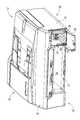
図1は、本発明に係る液体供給装置であるリフィルユニット11を備えた複合機10の外観を示す斜視図である。複合機10は、プリンタ部12及びスキャナ部13を一体的に備えた多機能装置である。プリンタ部12及びスキャナ部13は、スキャナ部13を上側として上下二段に構成されている。プリンタ部12は、インクジェット記録方式を採用したプリンタである。スキャナ部13は、フラットベッドスキャナとオート・ドキュメント・フィーダ15とを有するスキャナである。なお、スキャナ部13は、本発明において任意の構成であるので、詳細な説明が省略される。<Overall Configuration of
FIG. 1 is a perspective view showing an external appearance of a
複合機10の外形は、高さより横幅及び奥行きが大きい幅広薄型の直方体である。プリンタ部12は、装置正面側に開口17が形成された筐体14を有する。開口17を通じて、プリンタ部12に、給紙トレイ及び排紙トレイが一体となった給紙カセット16(図2参照)が着脱可能である。なお、図1においては、図左手前側が装置正面側である。また、図1においては、給紙カセット16が取り外された状態の複合機10が示されている。 The outer shape of the
筐体14における装置正面右側には扉20が設けられている。扉20は、筐体14に対して開閉可能である。扉20が開かれると、装置内部へアクセス可能な開口18が開かれる。開口18を通じて、装置内部に設けられたリフィルユニット11にアクセス可能となる。つまり、開口18を通じて、インクカートリッジ30の交換が行われる。 A
複合機10の正面側には、操作パネル19が設けられている。図1には詳細に示されていないが、操作パネル19には、画像記録を開始又は中止するためのスタートキー/ストップキーなどの各種キーと、液晶ディスプレイからなる表示部が設けられている。これらの各種キーや表示部は、一般に複合機10に採用される公知の構成が採用される。 An
複合機10は、操作パネル19の下側にカードスロット21を有する。カードスロット21には、カード型の各種記憶媒体が装填される。複合機10は、カードスロット21に装填された各種記憶媒体が記憶する画像データ等を読み取って、プリンタ部12において画像記録を行う。 The
複合機10は、コンピュータやデジタルカメラなどの外部情報機器と接続されうる。複合機10は、外部情報機器から送信されたデータに基づいて、或いはスキャナ部13が読み取った画像データに基づいて、プリンタ部12において画像記録を行う。 The
<プリンタ部12>
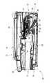
図2は、複合機10の内部構造を示す断面図である。<
FIG. 2 is a cross-sectional view showing the internal structure of the
給紙カセット16は、複合機10の開口17内に設けられている。給紙カセット16は、開口17を通じて複合機10に対して着脱可能である。給紙カセット16は、給紙トレイ22と排紙トレイ23とが、給紙トレイ22を下側として上下二段に構成されている。給紙トレイ22には、画像記録が行われる記録用紙が収容される。記録用紙は、本発明における被記録媒体の一例である。排紙トレイ23には、画像記録が行われた記録用紙が積載される。 The
給紙トレイ22は、複数枚の記録用紙を積載状態で収容可能な容器形状である。給紙トレイ22の奥側(図2における右側)には、分離傾斜板24が設けられている。給紙トレイ22から給送された記録用紙は、その先端が分離傾斜板24に案内されて上方へ向かう。分離傾斜板24には、搬送方向に沿って連続して突出する歯が設けられており、この歯によって、記録用紙が捌かれて分離される。 The
排紙トレイ23は、給紙トレイ22に支持された平板形状のものである。排紙トレイ23の奥側の端部は、給紙トレイ22の分離傾斜板24に対して手前側にオフセットされている。これにより、給紙トレイ22の奥側部分は、排紙トレイ23によって覆われておらず、上側に対して開口されている。この開口に後述される給紙ローラ27及びアーム28が降下する。 The
給紙トレイ22から排紙トレイ23へ搬送路25が形成されている。搬送路25は、給紙トレイ22の分離傾斜板24から上方へ向かってUターンして装置正面側へ延びて、排紙トレイ23へ通じている。搬送路25に案内されて、記録用紙が下方から上方へ反転される。搬送路25の上側部分には、画像記録部26が設けられている。画像記録部26は、搬送路25を搬送される記録用紙に画像記録を行う。搬送路25は、画像記録部26等が配設されている箇所以外では、所定間隔で対向する外側ガイド面と内側ガイド面とにより区画されている。外側ガイド面及び内側ガイド面は、プリンタ部12のフレームやガイド部材によって構成される。 A
給紙トレイ22の上側には、給紙ローラ27が設けられている。給紙ローラ27は、給紙トレイ22に積載された記録用紙と圧接して、記録用紙を搬送路25へ給送する。給紙ローラ27は、アーム28の先端に回転可能に支持されている。アーム28は、少なくとも給紙トレイ22と接離する範囲で揺動可能である。アーム28には、その延出方向に沿って駆動機構30が設けられている。駆動機構30は、ギヤ列である。駆動機構30によって駆動力が給紙ローラ27へ駆動伝達される。 A
画像記録部26は、キャリッジに搭載された記録ヘッドを主要構成とする。図には詳細に示されていないが、記録ヘッドは、その下面に各インク色に対応した複数のノズルを有する。各色インクのノズルは、それぞれ記録用紙搬送方向に列をなしており、その各色インクのノズル列が、キャリッジの往復動方向に並んでいる。このノズルから各色インクが微小なインク滴として選択的に吐出される。記録ヘッドには、リフィルユニット11に装着された各インクカートリッジ30から各色インクが供給される。 The
画像記録部26の上流側及び下流側には、ローラ対27,28がそれぞれ設けられている。ローラ対27,28は、搬送路25を搬送されている記録用紙を狭持してプラテン42上へ搬送し、画像記録後の記録用紙を排紙トレイ23へ排出する。 On the upstream and downstream sides of the
<リフィルユニット11>
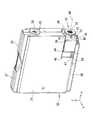
以下に本発明にかかる液体供給装置としてのリフィルユニット11が説明される。図3は、リフィルユニット11の外観構成を示す斜視図である。なお、図3では、1つのインクカートリッジ30のみが示されている。ケース本体60が、本発明にかかる容器装着装置に相当し、インクカートリッジ30が、本発明にかかる液体容器に相当する。<
Below, the
リフィルユニット11は、ケース本体60とインクカートリッジ30とに大別される。ケース本体60は、4つのケース61を有する。各ケース61は、1つのインクカートリッジ30を収容可能な空間を有する。各ケース61に装着されるインクカートリッジ30の種類は予め割り当てられている。本実施形態では、各ケース61には、インクカートリッジ30が収容するインク色に対応して割り当てが決められている。インクカートリッジ30は、本発明に係る液体容器の一例である。4つのインクカートリッジ30には、シアン、マゼンタ、イエロー、ブラックの各色の液体インクがそれぞれ収容されている。各インクカートリッジ30に収容された各色のインクは、インクチューブを通じて画像記録部26の記録ヘッドへ供給される。 The
<インクカートリッジ30>
以下に、本発明における液体容器としてのインクカートリッジ30の構造が説明される。図4及び図5は、インクカートリッジ30の外観構成を示す外観斜視図である。図4において、スライダ44は第1姿勢であり、図5において、スライダ44は第2姿勢である。インクカートリッジ30は、インク色に対応して複数種類があるが、各インクカートリッジ30は、収容するインクの色に対応して、スライダ44の構成が異なる他は、ほぼ同様の構成であるので、1つのインクカートリッジ30を例に説明がされる。インクカートリッジ30がインク色に応じて異なる構成を採る点は、適宜説明される。<
The structure of the
インクカートリッジ30は、左右一対のケース31,32を有する。ケース31,32は、インクカートリッジ30の挿抜方向を中心として、ほぼ対称な形状である。ケース31,32が合わせられることにより、中空形状の1つのケースが構成される。このケースは、薄型の略6面体である。図5において、x方向がインクカートリッジ30の挿入方向であり、y方向がインクカートリッジ30の厚み方向であり、z方向がインクカートリッジ30の高さ方向である。 The
一対のケース31,32の内部空間には、インク容器が収容されている。なお、各図にはインク容器は示されていない。インク容器は、その内部空間に各色のインクを収容する。このようなインク容器として、公知の形状が採用される。公知のインク容器として、例えば、樹脂製の容器や、樹脂フィルムからなるパック形状のものがあげられる。なお、インク容器は必須の構成ではなく、ケース31,32がインク容器を兼ねてもよい。 An ink container is accommodated in the internal space of the pair of
ケース31,32の背面側の下部には、インク供給バルブ33が設けられている。インク供給バルブ33は、本発明における液体供給部に相当する。インク供給バルブ33の一方端は、ケース31,32内のインク容器の内部と通じており、他方端はケース31,32の外側へ露出されている。インク供給バルブ33は、インク流路及びバルブを有する公知のバルブが採用されうる。インク流路は、インク供給バルブ33の両端に開口してインクが流通可能な流路である。図4においては、インク流路の一端である開口34が現れている。バルブは所謂逆止弁であり、プッシュロッド92〜95(図3参照)が開口34からインク供給バルブ33へ挿入されるとインク流路を開放し、プッシュロッド92〜95がインク供給バルブ33から抜けるとインク流路を閉塞する。このようなバルブは公知であるので詳細な構成の説明は省略される。インク供給バルブ33を通じて、インク容器内のインクが外部へ流出しうる。 An
ケース31,32の背面側の上部には、大気連通バルブ35が設けられている。大気連通バルブ35の一方端は、ケース31,32内のインク容器の内部と通じており、他方端はケース31,32の外側へ露出されている。大気連通バルブ35は、大気流路及びバルブを有する公知のバルブが採用されうる。大気流路は、インク供給バルブ33の両端に開口して大気が流通可能な流路である。図4においては、大気流路の一端である開口36が現れている。バルブは所謂逆止弁であり、プッシュロッド65(図3参照)が開口36から大気連通バルブ35へ挿入されると大気流路を開放し、プッシュロッド65が大気連通バルブ35から抜けると大気流路を閉塞する。このようなバルブは公知であるので詳細な構成の説明は省略される。大気連通バルブ35を通じて、インク容器154内の空間が大気圧となるべく、外気が流出入する。 At the upper part on the back side of the
ケース31,32の上下面には、レール37,38が形成されている。各レール37,38は、上面又は下面から上方又は下方へ突出して、インクカートリッジ30の挿入方向へ延びている。レール37,38は、ケース61のガイド溝63,64(図3参照)とそれぞれ嵌合する。レール37,38とガイド溝63,64との嵌合により、インクカートリッジ30はケース61に対して位置決めされるとともに、挿抜方向へスライド可能に案内される。
図5に示されるように、インク供給バルブ33の周囲には、管体39が設けられている。管体39は、インク供給バルブ33に外嵌可能な円管である。管体39は、インク供給バルブ33のインク流路と同じ方向を軸線40として、インク供給バルブ33の周囲に設けられている。管体39におけるケース31,32の背面側の端面は、インク供給バルブ33の外周に形成されたフランジ41と当接している。この当接によって、管体39が、インク供給バルブ33に係止されて、インク供給バルブ33と一体にされている。管体39は、軸線40周りに回転可能である。つまり、管体39は、軸線40方向へ移動することなく、軸線40周りに回転可能である。 As shown in FIG. 5, a
管体39の外周面におけるフランジ41の近傍から、突起42,43が放射状に外側へ突出されている。各突起42,43は円柱形状であり、軸線40と直交する方向へ突出する。突起42,43は、管体39の周方向に対して均等に配置されている。本実施形態では、管体39に2つの突起42,43が設けられており、各突起42,43は管体39の周方向に対して180°の回転位置にある。つまり、各突起42,43は、相互に反対方向へ突出している。各突起42,43と管体39とは一体であり、管体39が回転すると各突起42,43も回転する。各突起42,43は、管体39と共に回転しながら、第1溝101又は第2溝102へ選択的に挿抜されるが、この動作については後述される。 From the vicinity of the
ケース31,32には、管体39を覆う位置にスライダ44が設けられている。スライダ44は、本発明における位置決め部材に相当する。ケース31,32の背面側の下端部は、管体39が外嵌されたインク供給バルブ33の周囲を欠切した空間45が形成されている。また、ケース31,32には、空間45から挿入方向と反対方向(x方向と反対方向)へ延びる凹陥部46が形成されている。凹陥部46は、スライダ44の大きさ及びスライド・ストロークに対応してケース31の側面が凹陥された部分である。なお、図4及び図5においては、ケース31の凹陥部46のみが現れているが、ケース32にも同様の凹陥部が形成されている。 In the
スライダ44は、管体39が外嵌されたインク供給バルブ33の周囲を覆う立方体形状である。スライダ44は、空間45に配置された状態で、ケース31,32の両側面と同一面をなす大きさである。各図には詳細に現れていないが、スライダ44の内部には、管体39が外嵌されたインク供給バルブ33を収容可能な空間が形成されている。 The
ケース31,32において、凹陥部46にはガイド溝47が凹設されている。また、レール38にはガイド溝48が形成されている。スライダ44の内部空間側には、ガイド溝47と嵌合する突起が形成されているが、各図には現れていない。スライダ44の下端には、レール49が形成されている。レール49は、スライダ44の下面から下方へ突出して、スライダ44のスライド方向へ延びている。レール49は、ガイド溝48と嵌合する。これらの嵌合により、スライダ44は、ケース31,32に対してインクカートリッジ30の挿抜方向へスライド可能に案内される。 In the
スライダ44におけるケース31,32の背面側の端面には、2つの突起43,44に対応したガイド孔50,51が形成されている。ガイド孔50,51は、スライダ44の端面に開口して、スライダ44のスライド方向へ延びている。各ガイド孔50,51は、2つの突起43,44をそれぞれ収容可能である。各突起43,44は同一形状であるので、各ガイド孔50,51も同一形状である。したがって、各ガイド孔50,51は、いずれの突起43,44も収容可能である。 Guide holes 50 and 51 corresponding to the two
ガイド孔50,51は、軸線40に対して上下方向に配置されている。ガイド孔50,51の配置は、インクカートリッジ30が収容するインクの色に対応している。ここで説明されるインクカートリッジ30は、シアン・インクを収容するものである。その他のインクカートリッジ30におけるスライダ44のガイド孔50,51は、軸線40に対して上下方向と異なる位置にある。詳細には、マゼンタ・インクを収容するインクカートリッジ30におけるスライダ44のガイド孔50,51は、図4において軸線40に対して仮想線52に示される位置にある。イエロー・インクを収容するインクカートリッジ30におけるスライダ44のガイド孔50,51は、図4において軸線40に対して仮想線53に示される位置にある。ブラック・インクを収容するインクカートリッジ30におけるスライダ44のガイド孔50,51は、図4において軸線40に対して仮想線53に示される位置にある。 The guide holes 50 and 51 are arranged in the vertical direction with respect to the
スライダ44は、x方向へスライドすることにより、図4に示されるように、突起43,44をガイド孔50,51内に収容する第1姿勢と、図5に示されるように、突起43,44をガイド孔50,51から露出させる第2姿勢とに姿勢変化される。第1姿勢のスライダ44により突起43,44がガイド孔50,51に収容されると、管体39は軸線40周りに回転することができない。つまり、管体39が回転方向に対して固定される。スライダ44が第2姿勢となると、突起43,44がガイド孔50,51から抜け出るので、管体39が軸線40周りに自由に回転する。つまり、第2姿勢のスライダ44は、管体39の自由な回転を許容する。 The
図5に示されるように、ケース31,32におけるガイド溝48内には、コイルバネ55が挿入されている。コイルバネ48は、ガイド溝48の奥面をバネ座として、スライダ44のスライド方向へ伸縮可能である。コイルバネ48はスライダ44を第1姿勢へ弾性付勢する。これにより、スライダ44は、外力が付与されない限り、第1姿勢が維持される。 As shown in FIG. 5, a
<ケース61>
図3に示されるように、ケース本体11には、4つの各ケース61が幅方向に並設されている。ケース本体11は、正面側が開口した略6面体の容器形状である。ケース本体11の正面側には、インクカートリッジ30をジョイント部66に連結された状態に保持するための蓋などが設けられていない。当該開口を通じて、各ケース61にインクカートリッジ30が挿抜される。各ケース61の上面及び下面には、ガイド溝63,64がそれぞれ設けられている。前述されたように、インクカートリッジ30は、レール37,38がガイド溝63,64にそれぞれ嵌合されて、ケース61に対して挿抜される。<
As shown in FIG. 3, four
各ケース61の奥部にはプッシュロッド65がそれぞれ設けられている。プッシュロッド65は、ケース61の奥面から正面側へ突出された中空管である。プッシュロッド65は、インクカートリッジ30がケース61に挿入される過程において、インクカートリッジ30に設けられた大気連通バルブ35へ挿入される。つまり、プッシュロッド65は、インクカートリッジ30の大気連通バルブ35と対応する位置にある。 Push
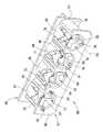
各ケース61の奥部には、ジョイント部66が設けられている。ジョイント部66は、インクカートリッジ30のインク供給バルブ33と連結される。図6に示されるように、ジョイント部66は、4つのケース61に対して一体に形成されている。ジョイント部66は、ケース61において正面側に配置される第1部材67と、ケース61において背面側に配置される第2部材68との2つの部材からなる。なお、図6において、図左手前側がケース61の正面側である。 A
第1部材67は、ベース板69と、ベース板69から第2部材68へ向かって突出する4つの円筒部70〜73とからなる。ベース板69が、本発明における当接部材に相当する。ベース板69は、4つのケース61に対して幅方向に長い平板であり、各ケース61の奥部において垂直面をなす。ベース板61には、4つの開口74〜77が長手方向に並んで形成されている。4つの円筒部70〜73は、開口74〜77を奥部へ連続させるように延出されている。開口74〜77及び円筒部70〜73により形成される空間には、各インクカートリッジ30におけるインク供給バルブ33及び管体39が挿入可能である。 The
開口74〜77には、管体39の突起42,43に対応して挿入口78〜85が設けられている。各挿入口78〜85は、各開口74〜77において、軸線方向に対する位置が異なる他は同様の構成なので、開口74に形成された挿入口78,79を例に詳細な構成が説明される。 In the
挿入口78,79は、開口74において、軸線86に対する上下方向に開口74の径を一部拡大するように形成されている。挿入口78,79の形状は、略矩形であり、突起42,43に対応している。したがって、開口74に管体39が挿入される際に、突起42,43が、挿入口78,79へ挿入される。 The
挿入口78,79の配置は、シアン・インクを収容するインクカートリッジ30における突起42,43の位置に対応されている。図4に示されるように、シアン・インクを収容するインクカートリッジ30において、突起42,43は、第1姿勢のスライダ44によって軸線40に対する上下方向に位置決めされている。挿入口78,79は、当該位置の突起42,43に対応しており、インクカートリッジ30のインク供給バルブ33がジョイント部66に連結される際に、突起42,43が挿入口78,79を通過する。 The arrangement of the
他の開口75〜78における各挿入口80〜85は、マゼンタ・インクを収容するインクカートリッジ30における突起42,43が第1姿勢のスライダ44によって位置決めされる位置(仮想線52)、イエロー・インクを収容するインクカートリッジ30における突起42,43が第1姿勢のスライダ44によって位置決めされる位置(仮想線53)、ブラック・インクを収容するインクカートリッジ30における突起42,43が第1姿勢のスライダ44によって位置決めされる位置(仮想線54)にそれぞれ対応している。 The
各円筒部70〜73の延出端は、第2部材68の各円筒88〜91の延出端と対向して、第1溝101及び第2溝102を形成する。第1溝101及び第2溝102については後述される。 The extending ends of the
第2部材68は、ベース板87と、ベース板87から第1部材67へ向かって突出する4つの円筒部88〜91と、ベース板87から各円筒部88〜91の軸線方向へ突出する4つのプッシュロッド92〜95とからなる。ベース板87は、4つのケース61に対して幅方向に長い平板であり、第1部材67のベース板69と所定の間隔で対向される。ベース板87には、4つの円筒部88〜91が、4つのケース61に対応して幅方向に併設されている。各円筒部88〜91は、第1部材67における各円筒部70〜73と対向して、各円筒部70〜73と同軸に配置されている。したがって、各円筒部70〜73により形成される空間は、各円筒部88〜91によってベース板87側へ連続されている。各円筒部88〜91により形成される空間にも、各インクカートリッジ30におけるインク供給バルブ33及び管体39が挿入可能である。 The
プッシュロッド92〜95は、各円筒部88〜91の軸線方向へ突出された中空管である。例えば、円筒部88に対応するプッシュロッド92は、軸線86方向へ突出されている。プッシュロッド92〜95は、インクカートリッジ30がケース61に挿入される過程において、インクカートリッジ30に設けられたインク供給バルブ33へ挿入される。つまり、プッシュロッド92〜95は、各インクカートリッジ30のインク供給バルブ33と対応する位置にある。 The
各円筒部88〜91の延出端は、第1部材67の各円筒部70〜73の延出端と対向して、第1溝101及び第2溝102を形成する。以下に、第1溝101及び第2溝102について詳述される。 The extending ends of the cylindrical portions 88 to 91 are opposed to the extending ends of the
第1部材67の各円筒部70〜73の延出端と、第2部材68の各円筒部88〜91の延出端とが所定間隔で対向されることにより、本発明にかかる係合溝が形成されている。各係合溝は第1溝及び第2溝を有するが、4つのケース61にそれぞれ対応した係合溝は、その形状が軸線の周方向に回転されているほかは同様であるので、円筒部70と円筒部88とによって形成される係合溝(第1溝101,第2溝102)を例に詳細な構成が説明される。 The extending grooves of the
図6に示されるように、係合溝(第1溝101,第2溝102)は、ジョイント部66において円筒部70及び円筒部88周りに形成されている。図7は、第1溝101及び第2溝102を平面上に展開した図であり、円筒部70及び円筒部88の最上部から図6手前側からみて反時計回りに半周分の円筒部70及び円筒部88における外周面が示されている。円筒部70及び円筒部88の最下部から反時計回りに半周分の円筒部70及び円筒部88においても、同様の第1溝101及び第2溝102が形成されている。つまり、円筒部70及び円筒部88の外周面には、2組の第1溝101及び第2溝102が、軸線86に対して180°異なる回転位置に連続して形成されている。これらは突起42,43のいずれが挿抜されるかが異なる他は同様の構成なので、一方の第1溝101及び第2溝102を例に説明がされる。また、図7において上下方向がインクカートリッジ30の挿抜方向である。 As shown in FIG. 6, the engagement grooves (first groove 101 and second groove 102) are formed around the
第1溝101及び第2溝102は、前述されたように、円筒部70の延出端96と、円筒部88の延出端97とが所定間隔で対向されて形成されている。延出端96と延出端97との間隔は、突起42,43が移動可能に設定される。延出端96及び延出端97は、第1溝101及び第2溝102を移動する突起42,43に対して、ガイドとして機能する。 As described above, the first groove 101 and the
第1溝101は、挿入溝101A及び脱抜溝101Bを有する。また、挿入口78,79も第1溝101に含まれる。挿入溝101Aは、挿入口78から反時計回り(図7における左方向)、かつ奥側(図7における上側)へ延びる空間として形成されている。挿入溝101Aにおいて、突起42,43は矢印103の方向へ移動される。脱抜溝101Bは、挿入口79から時計回り(図7における右方向)、かつ奥側(図7における上側)へ延びる空間として形成されている。脱抜溝101Bにおいて、突起42,43は矢印104の方向へ移動される。この挿入溝101において挿入口78,79が延びる図7の上方向が、本発明における第1方向である。 The first groove 101 has an
第2溝102は、挿入溝101A及び脱抜溝101Bと連続する溝である。第2溝102は、挿入溝101Aの奥側及び脱抜溝101Bの奥側から、それぞれ手前側(図7における下側)へ斜め方向へ延びて結合される略V字形状である。第2溝102において、突起42,43は矢印105の方向へ移動される。V字形状の第2溝102における隅において、突起42,43が、インクカートリッジ30がケースから脱抜する方向に対して規制される。インクカートリッジ30がケースから脱抜する方向(図7における下方向)が、本発明における第2方向である。突起42,43と第2溝102との係合によって、インク供給バルブ33の周囲において、第2方向に対してインク供給バルブ33がジョイント部66から移動することが禁止される。 The
ジョイント部66に形成された第1溝101及び第2溝102と、インクカートリッジ30の管体39に形成された突起42,43との協働によって、本発明におけるロック機構が実現されている。このロック機構は、インク供給バルブ33とジョイント部66とが連結された状態を維持する。 The locking mechanism in the present invention is realized by the cooperation of the first groove 101 and the
<インクカートリッジ30の着脱>
以下に、ケース61にインクカートリッジ30が着脱される動作が説明される。以下には、シアン・インクを収容するインクカートリッジ30の着脱が一例として説明される。図8は、ケース61にインクカートリッジ30が装着される過程を示す図である。図9は、ケース61の奥部へインクカートリッジ30が押し込まれた状態を示す図である。図10は、ケース61にインクカートリッジ30が装着された状態を示す図である。図11は、装着状態からケース61の奥部へインクカートリッジ30が押し込まれた状態を示す図である。<Removal of
Hereinafter, an operation of attaching / detaching the
図8に示されるように、インクカートリッジ30は、レール37,38がガイド溝63,64にそれぞれ嵌合されて、ケース61に対して挿入される。この状態において、インクカートリッジ30のスライダ44には、外力が付与されていない。したがって、スライダ44はコイルバネ48に付勢されて第1姿勢を維持する。第1姿勢のスライダ44によって、管体39は、突起43,44がガイド孔50,51に収容された状態で回転が禁止されている。突起43,44はガイド孔50,51によって、軸線40,86に対して上下方向に位置決めされている。 As shown in FIG. 8, the
図8に示される位置から、さらにインクカートリッジ30がケース61の奥部へ挿入されることにより、プッシュロッド65が、インクカートリッジ30の大気連通バルブ35へ挿入される。また、プッシュロッド92が、インク供給バルブ33へ挿入される。また、スライダ44の背面が、ジョイント部66におけるベース板69と当接する。 When the
スライダ44がベース板69と当接してから、さらにインクカートリッジ30がケース61の奥部へ挿入されることにより、スライダ44がコイルバネ55の付勢力に抗してスライドされて、第1姿勢から第2姿勢へ姿勢変化される。この姿勢変化によって、管体39の突起42,43がガイド孔50,51から抜け出て、管体39の自由回転が許容される。スライダ44が姿勢変化されると同時に、ガイド孔50,51から抜け出た突起42,43は、ジョイント部66における挿入口78,79へ進入する。そして、管体39が円筒部70及び円筒部88の内部を奥側へ進むにつれて、突起42,43は、第1溝101である挿入溝101Aに沿って移動するとともに、管体39が軸線40,86周りに回転される。 After the
第1溝101及び第2溝102における突起42,43の移動は、軸線40,86に対する回転位置が異なる他は同様なので、図7においては、突起42の移動を例に説明がされる。 Since the movements of the
突起42は、第1姿勢のスライダ44のガイド孔50によって、軸線40,86に対して上側へ位置決めされているので、突起42の位置は挿入口78に対応している。したがって、突起42は、インクカートリッジ30の挿入過程において、スライダ44のガイド孔50から抜け出て挿入口78へ進入する。これにより、シアン・インクに割り当てられたケース61に対して、シアン・インクを収容するインクカートリッジ30が装着可能となる。 Since the
ところで、図6に示されたように、他のケース61において、挿入口80〜85は軸線に対して上下方向にない。仮に、シアン・インクを収容するインクカートリッジ30が、シアン・インクに割り当てられていない他のケース61に挿入されると、スライダ44によって上下方向に位置決めされた突起42,43は、他のケース61において挿入口80〜85へ進入することができず、ベース板69と当接する。突起42,43とベース板69との当接により、インクカートリッジ30がさらに奥側へ挿入されることが禁止される。これにより、割り当てと異なるインク色を収容するインクカートリッジ30がケース61に装着されることがない。 By the way, as FIG. 6 showed, in the
挿入口78へ進入した突起42は、円筒部88の延出端97におけるガイド面111に案内されて、管体39を反時計回りに回転させながら挿入溝101Aを矢印103へ移動する。そして、図9に示されるように、インクカートリッジ30がケース61の最も奥部まで押し込まれると、ガイド面111の奥側である位置112に到達する。 The
図9に示された状態から、インクカートリッジ30への押し込む力が開放されると、スライダ44がコイルバネ55の付勢力によって、第2姿勢から第1姿勢へ復帰しようとスライドする。スライダ44のスライドによって、インクカートリッジ30は、図9に示された状態から脱抜方向(図9における左方向)へ移動する。 When the pushing force to the
位置112に到達した突起42は、インクカートリッジ30が脱抜方向へ移動すると、挿入溝101Aから第2溝102へ進入する。つまり、位置112から正面側(図7における下側)へ移動した突起42は、円筒部70の延出端96におけるガイド面113に案内されて、管体39を回転させながら第2溝102を矢印105へ移動する。そして、その移動過程において位置114へ到達する。 The
位置114はV字形状の第2溝102の隅である。換言すれば、正面側へ傾斜するガイド面113及びガイド面115とが連続する隅である。ガイド面113,115は、本発明における規制面に相当する。突起42は位置114より正面側へ移動することができない。突起42が位置114に到達しても、図10に示されるように、スライダ44は第1姿勢へ復帰していない。したがって、コイルバネ55にスライダ44が付勢され、これを受けてインクカートリッジ30は脱抜方向へ付勢力を受け続ける。この付勢力とガイド面113,115とによって、突起42が位置114に維持され、管体39がさらに回転されない。 The
前述されたように、突起42は、第2溝102において位置114から矢印105の方向またはその反対方向のいずれにも移動することがない。つまり、突起42と第2溝102との係合によって、インクカートリッジ30がジョイント部66と連結された状態が維持される。この状態が、ケース61にインクカートリッジ30が装着された状態である。装着状態において、インクカートリッジ30に収容されたシアン・インクは、インク供給バルブ33及びプッシュロッド92を通じて外部へ流出される。 As described above, the
装着状態からインクカートリッジ30が脱抜される場合は、図10に示した状態から、インクカートリッジ30がケース61の奥部へ押し込まれる。つまり、コイルバネ55によってスライダ44に付与される付勢力に抗してインクカートリッジ30が押し込まれる。これにより、図7に示されるように、第2溝102の位置114に位置する突起42が、ガイド面116に案内されて、管体39を反時計回りへ回転させながら第2溝102を矢印105へ移動する。そして、図11に示されるように、インクカートリッジ30がケース61の最も奥部まで押し込まれると、ガイド面116の奥側である位置117に到達する。 When the
図11に示された状態から、インクカートリッジ30への押し込む力が開放されると、スライダ44がコイルバネ55の付勢力によって、第2姿勢から第1姿勢へ復帰しようとスライドする。スライダ44のスライドによって、インクカートリッジ30は、図11に示された状態から脱抜方向へ移動する。 When the pushing force to the
位置117に到達した突起42は、インクカートリッジ30が脱抜方向へ移動すると、第2溝102から脱抜溝101Bへ進入する。つまり、位置117から正面側へ移動した突起42は、円筒部70の延出端96におけるガイド面118に案内されて、管体39を反時計回りへ回転させながら脱抜溝101Bを矢印104へ移動する。そして、挿入口79から抜け出る。これにより、ロック機能によるロックが解除されて、インク供給バルブ33がジョイント部66から離脱することが可能となり、インクカートリッジ30をケース61から脱抜することができる。 The
このように、インク供給バルブ33とジョイント部66とが連結された状態を維持するロック機構がインク供給バルブ33の周囲に設けられているので、インク供給バルブ33とジョイント部66との連結又は脱離に際して、インク供給バルブ33において連結方向(軸線40,86)と異なる方向へ大きなモーメントが生じない。これにより、インクカートリッジ30の着脱に際してインクカートリッジ30がこじられることがなく、操作感に優れたインクカートリッジ30の着脱が実現される。 As described above, since the lock mechanism for maintaining the state where the
また、インクカートリッジ30はの着脱に際して、並びにインクカートリッジ30がジョイント部66に連結された状態において、プッシュロッド92〜95がインク供給バルブ33に対してこじられることがなく、インクの漏出を抑制される。 Further, when the
さらに、インク供給バルブ33の周囲にロック機構が設けられることにより、ケース本体61の正面側にインクカートリッジ30をジョイント部66に連結された状態に保持するための蓋などを設ける必要がない。したがって、リフィルユニット100のサイズ、特に奥行き方向のサイズを小さくすることが可能となり、その結果、プリンタ部12の小型化が実現される。 Further, since a lock mechanism is provided around the
前述されたロック機構は、管体39に形成された突起42,43と第1係合溝101及び第2係合溝102との協働により実現されており、突起42,43は、管体39の周方向に2つが配置されている。これにより、2つの突起42,43が第2溝102のガイド面113,115にそれぞれ規制されるので、インク供給バルブ33において、連結方向と異なる方向へモーメントが生じにくいという利点がある。 The locking mechanism described above is realized by the cooperation of the
また、2つの突起42,43は、管体39の周方向に対して均等に配置されているので、各突起42,43が第2溝102のガイド面113,115にそれぞれ規制されることにより生じるモーメントが、インク供給バルブ33の周方向において相殺されるという利点がある。なお、本発明において管体における突起の数は2つに限定されないことは言うまでもない。 In addition, since the two
また、管体39に設けられた突起42,43は、第1姿勢のスライダ44によって所定の回転位置に固定されるので、未装着状態のインクカートリッジ30における突起42,43の位置が固定される。一方、第2姿勢のスライダ44によって、管体39が自由に回転されるので、前述されたロック動作又は解除動作において、突起42,43が第1溝101と第2溝102とを移動することが許容される。 Further, since the
また、スライダ44がスライドによって姿勢変化し、ケース61にインクカートリッジ30が装着される過程において、ベース板69と当接することにより、スライダ44がスライドされるので、ユーザがスライダ44を操作する必要がなく、インクカートリッジ30の装着作業が簡易となる。 Further, in the process in which the
また、スライダ44は、コイルバネ55に付勢されることにより、未装着状態のインクカートリッジ30において第1姿勢に維持され、常に突起42,43の位置を固定する。また、インクカートリッジ30がケース61から脱抜される際に、スライダ44が第2姿勢から第1姿勢へ姿勢変化して、突起42,43の位置を固定する。これにより、ユーザが不用意に突起42,43の位置を変更することが防止される。さらに、インクカートリッジ30がケース61から脱抜される際に、コイルバネ55の付勢力が脱抜を補助する。これにより、円滑なインクカートリッジ30の脱抜が実現される。 Further, the
また、スライダ44は、第1姿勢において、インクカートリッジ30が収容するインク色に対応した所定の回転位置において管体39を固定し、挿入口78,79は、そのケース61が収容すべきインクカートリッジ30における管体39の所定の回転位置に対応しているので、そのケース61に割り当てられたインクカートリッジ30がそのケース61に装着され、一方、割り当てと異なるインクカートリッジ30は、そのケース61に装着することができない。これにより、割り当てと異なるインクカートリッジ30がケース61に装着されることが防止できる。 Further, in the first posture, the
なお、本実施形態において、本発明におけるロック機構が、インク供給バルブ33に設けられた管体39及び突起42,43と、ジョイント部66に設けられた第1係合溝101及び第2係合溝102とによって実現されているが、これらの構成は、インク供給バルブ33及びジョイント部66において相対的に変更されてもよい。 In the present embodiment, the lock mechanism in the present invention includes the
また、本発明において液体はインクに限定されない。したがって、燃料電池における液体燃料を供給するための液体供給装置として本発明が実現されてもよい。 In the present invention, the liquid is not limited to ink. Therefore, the present invention may be realized as a liquid supply device for supplying liquid fuel in a fuel cell.
11・・・リフィルユニット(液体供給装置)
12・・・プリンタ部(画像記録装置)
26・・・画像記録部
30・・・インクカートリッジ(液体容器)
33・・・インク供給バルブ(液体供給部)
39・・・管体
42,43・・・突起
44・・・スライダ(位置決め部材)
61・・・ケース
66・・・ジョイント部
69・・・ベース板(当接部材)
101・・・第1溝
102・・・第2溝
113,114・・・ガイド面(規制面)11 ... Refill unit (liquid supply device)
12: Printer unit (image recording device)
26: Image recording unit 30: Ink cartridge (liquid container)
33 ... Ink supply valve (liquid supply part)
39 ...
61 ...
101 ... 1st groove | channel 102 ... 2nd groove | channel 113,114 ... guide surface (regulation surface)
Claims (12)
Translated fromJapanese上記液体供給部と連結されるジョイント部を有し、上記液体容器が装着されるケースと、
上記液体供給部の周囲に設けられて、液体供給部とジョイント部とが連結された状態を維持するロック機構と、を具備する液体供給装置。A liquid container having a liquid supply part for flowing out the liquid contained in the internal space to the outside;
A joint portion connected to the liquid supply portion, and a case to which the liquid container is attached;
A liquid supply device comprising: a lock mechanism provided around the liquid supply unit and maintaining a state in which the liquid supply unit and the joint unit are connected to each other.
上記液体供給部又は上記ジョイント部のいずれか一方に設けられ、液体供給部とジョイント部とが着脱される第1方向へ延びる第1溝、及び上記液体容器が上記ケースから脱抜される第2方向に対する規制面となる第2溝を有する係合溝と、
上記液体供給部又は上記ジョイント部のいずれか他方に設けられて、上記係合溝に対して相対的に回転することにより上記第1溝又は上記第2溝へ選択的に挿抜される突起と、を具備する請求項1に記載の液体供給装置。The locking mechanism is
A first groove provided in either the liquid supply part or the joint part and extending in a first direction in which the liquid supply part and the joint part are attached and detached, and a second groove in which the liquid container is removed from the case. An engagement groove having a second groove serving as a restriction surface with respect to the direction;
A protrusion that is provided on either the liquid supply part or the joint part and is selectively inserted into and removed from the first groove or the second groove by rotating relative to the engagement groove; The liquid supply apparatus according to claim 1, comprising:
上記突起は、上記液体供給部の周囲に回転可能に設けられた管体に形成されたものである請求項2に記載の液体供給装置。The engagement groove is formed around the joint portion,
The liquid supply apparatus according to claim 2, wherein the protrusion is formed on a tube body rotatably provided around the liquid supply unit.
上記ケースは、上記液体容器が装着される過程において上記位置決め部材と当接して、当該位置決め部材を第1姿勢から第2姿勢へ姿勢変化させる当接部材を具備する請求項6に記載の液体供給装置。The positioning member is changed in posture between a first posture and a second posture by sliding,
The liquid supply according to claim 6, wherein the case includes a contact member that contacts the positioning member in a process of mounting the liquid container and changes the position of the positioning member from the first posture to the second posture. apparatus.
上記係合溝の第1溝は、当該ケースが収容すべき上記液体容器における上記管体の所定の回転位置に対応して、その回転位置における上記突起が挿抜可能である請求項6から8のいずれかに記載の液体供給装置。The positioning member fixes the tubular body at a predetermined rotational position corresponding to the type of the liquid container or the type of liquid contained in the liquid container,
The first groove of the engagement groove can be inserted and removed in the rotation position corresponding to a predetermined rotation position of the tubular body in the liquid container to be accommodated in the case. The liquid supply apparatus according to any one of the above.
上記ケースに設けられて上記液体供給部と連結されるジョイント部と、
上記ジョイント部に設けられ、上記液体供給部と協働して当該液体供給部と当該ジョイント部とが連結された状態を維持するロック機構と、を具備する容器装着装置。A case in which a liquid container having a liquid supply part for flowing out the liquid stored in the internal space to the outside is mounted;
A joint part provided in the case and connected to the liquid supply part;
A container mounting device comprising: a lock mechanism provided in the joint portion and maintaining a state where the liquid supply portion and the joint portion are connected in cooperation with the liquid supply portion.
上記容器本体に設けられて、上記液体を外部へ流出させる液体供給部と、
上記液体供給部に設けられ、当該液体供給部と連結されるジョイント部と協働して、当該液体供給部と当該ジョイント部とが連結された状態を維持するロック機構と、を具備する液体容器。A container body for storing a liquid in an internal space;
A liquid supply section provided in the container body for allowing the liquid to flow to the outside;
A liquid container comprising: a lock mechanism provided in the liquid supply unit and maintaining a state where the liquid supply unit and the joint unit are connected in cooperation with a joint unit connected to the liquid supply unit .
上記液体容器から供給された液体を用いて被記録媒体に画像記録を行う画像記録部と、を具備する画像記録装置。A liquid supply device according to any one of claims 1 to 9, or a container mounting device according to claim 10,
An image recording apparatus comprising: an image recording unit configured to record an image on a recording medium using the liquid supplied from the liquid container.
Priority Applications (1)
| Application Number | Priority Date | Filing Date | Title |
|---|---|---|---|
| JP2007049264AJP2008213147A (en) | 2007-02-28 | 2007-02-28 | Liquid supply apparatus and image recording apparatus |
Applications Claiming Priority (1)
| Application Number | Priority Date | Filing Date | Title |
|---|---|---|---|
| JP2007049264AJP2008213147A (en) | 2007-02-28 | 2007-02-28 | Liquid supply apparatus and image recording apparatus |
Publications (1)
| Publication Number | Publication Date |
|---|---|
| JP2008213147Atrue JP2008213147A (en) | 2008-09-18 |
Family
ID=39833795
Family Applications (1)
| Application Number | Title | Priority Date | Filing Date |
|---|---|---|---|
| JP2007049264APendingJP2008213147A (en) | 2007-02-28 | 2007-02-28 | Liquid supply apparatus and image recording apparatus |
Country Status (1)
| Country | Link |
|---|---|
| JP (1) | JP2008213147A (en) |
Cited By (16)
| Publication number | Priority date | Publication date | Assignee | Title |
|---|---|---|---|---|
| JP2013540066A (en)* | 2010-10-22 | 2013-10-31 | ヒューレット−パッカード デベロップメント カンパニー エル.ピー. | Fluid cartridge |
| JP2015110339A (en)* | 2015-01-28 | 2015-06-18 | ヒューレット−パッカード デベロップメント カンパニー エル.ピー.Hewlett‐Packard Development Company, L.P. | Fluid cartridges |
| CN105128537A (en)* | 2011-03-30 | 2015-12-09 | 兄弟工业株式会社 | Ink cartridge and recording apparatus |
| JP2016120720A (en)* | 2016-02-04 | 2016-07-07 | ヒューレット−パッカード デベロップメント カンパニー エル.ピー.Hewlett‐Packard Development Company, L.P. | Fluid cartridge |
| JP2016137729A (en)* | 2016-05-12 | 2016-08-04 | セイコーエプソン株式会社 | Printing material storage container |
| JP2016164003A (en)* | 2016-05-12 | 2016-09-08 | セイコーエプソン株式会社 | Printing material storage container |
| JP2017052122A (en)* | 2015-09-07 | 2017-03-16 | ブラザー工業株式会社 | Liquid cartridge and a set of liquid cartridge |
| US9616670B2 (en) | 2010-10-22 | 2017-04-11 | Hewlett-Packard Development Company, L.P. | Fluid cartridge |
| JP2017109495A (en)* | 2010-12-22 | 2017-06-22 | セイコーエプソン株式会社 | cartridge |
| KR101911128B1 (en)* | 2012-01-13 | 2018-10-23 | 세이코 엡슨 가부시키가이샤 | Cartridge, printing material supply system, printing apparatus, liquid accommodation container, a printing system, and a terminal connection structure |
| US10118399B2 (en) | 2017-03-27 | 2018-11-06 | Brother Kogyo Kabushiki Kaisha | Liquid cartridge provided with snap-fit mechanism capable of suppressing detachment of cap |
| WO2019026100A1 (en)* | 2017-07-31 | 2019-02-07 | Brother Kogyo Kabushiki Kaisha | Liquid cartridge and system therefor |
| US10343410B2 (en) | 2017-03-27 | 2019-07-09 | Brother Kogyo Kabushiki Kaisha | Liquid cartridge capable of reducing remaining amount of liquid in liquid storage chamber |
| US10357976B2 (en) | 2017-03-27 | 2019-07-23 | Brother Kogyo Kabushiki Kaisha | Liquid cartridge provided with liquid supply portion having guide groove |
| US10449771B2 (en) | 2017-03-27 | 2019-10-22 | Brother Kogyo Kabushiki Kaisha | Liquid cartridge capable of improving visibility to liquid stored in liquid storage chamber |
| US10493765B2 (en) | 2017-03-27 | 2019-12-03 | Brother Kogyo Kabushiki Kaisha | Liquid cartridge capable of reducing leakage of liquid from liquid storage chamber |
- 2007
- 2007-02-28JPJP2007049264Apatent/JP2008213147A/enactivePending
Cited By (29)
| Publication number | Priority date | Publication date | Assignee | Title |
|---|---|---|---|---|
| US9770914B2 (en) | 2010-10-22 | 2017-09-26 | Hewlett-Packard Development Company, L.P. | Fluid cartridge |
| JP2013540066A (en)* | 2010-10-22 | 2013-10-31 | ヒューレット−パッカード デベロップメント カンパニー エル.ピー. | Fluid cartridge |
| US10112400B2 (en) | 2010-10-22 | 2018-10-30 | Hewlett-Packard Development Company, L.P. | Fluid cartridge |
| US10391775B2 (en) | 2010-10-22 | 2019-08-27 | Hewlett-Packard Development Company, L.P. | Fluid cartridge |
| US9616670B2 (en) | 2010-10-22 | 2017-04-11 | Hewlett-Packard Development Company, L.P. | Fluid cartridge |
| KR101729592B1 (en)* | 2010-10-22 | 2017-05-11 | 휴렛-팩커드 디벨롭먼트 컴퍼니, 엘.피. | Fluid cartridge |
| US9738080B1 (en) | 2010-10-22 | 2017-08-22 | Hewlett-Packard Development Company, L.P. | Fluid cartridge |
| JP2017109495A (en)* | 2010-12-22 | 2017-06-22 | セイコーエプソン株式会社 | cartridge |
| CN105128537A (en)* | 2011-03-30 | 2015-12-09 | 兄弟工业株式会社 | Ink cartridge and recording apparatus |
| KR101911128B1 (en)* | 2012-01-13 | 2018-10-23 | 세이코 엡슨 가부시키가이샤 | Cartridge, printing material supply system, printing apparatus, liquid accommodation container, a printing system, and a terminal connection structure |
| JP2015110339A (en)* | 2015-01-28 | 2015-06-18 | ヒューレット−パッカード デベロップメント カンパニー エル.ピー.Hewlett‐Packard Development Company, L.P. | Fluid cartridges |
| JP2017052122A (en)* | 2015-09-07 | 2017-03-16 | ブラザー工業株式会社 | Liquid cartridge and a set of liquid cartridge |
| JP2016120720A (en)* | 2016-02-04 | 2016-07-07 | ヒューレット−パッカード デベロップメント カンパニー エル.ピー.Hewlett‐Packard Development Company, L.P. | Fluid cartridge |
| JP2016164003A (en)* | 2016-05-12 | 2016-09-08 | セイコーエプソン株式会社 | Printing material storage container |
| JP2016137729A (en)* | 2016-05-12 | 2016-08-04 | セイコーエプソン株式会社 | Printing material storage container |
| US10118399B2 (en) | 2017-03-27 | 2018-11-06 | Brother Kogyo Kabushiki Kaisha | Liquid cartridge provided with snap-fit mechanism capable of suppressing detachment of cap |
| US10703107B2 (en) | 2017-03-27 | 2020-07-07 | Brother Kogyo Kabushiki Kaisha | Liquid cartridge provided with liquid supply portion having guide groove |
| US10357976B2 (en) | 2017-03-27 | 2019-07-23 | Brother Kogyo Kabushiki Kaisha | Liquid cartridge provided with liquid supply portion having guide groove |
| US11897267B2 (en) | 2017-03-27 | 2024-02-13 | Brother Kogyo Kabushiki Kaisha | Liquid cartridge capable of reducing leakage of liquid from liquid storage chamber |
| US10449771B2 (en) | 2017-03-27 | 2019-10-22 | Brother Kogyo Kabushiki Kaisha | Liquid cartridge capable of improving visibility to liquid stored in liquid storage chamber |
| US10493765B2 (en) | 2017-03-27 | 2019-12-03 | Brother Kogyo Kabushiki Kaisha | Liquid cartridge capable of reducing leakage of liquid from liquid storage chamber |
| US11890876B2 (en) | 2017-03-27 | 2024-02-06 | Brother Kogyo Kabushiki Kaisha | Liquid cartridge provided with liquid supply portion having guide groove |
| US10343410B2 (en) | 2017-03-27 | 2019-07-09 | Brother Kogyo Kabushiki Kaisha | Liquid cartridge capable of reducing remaining amount of liquid in liquid storage chamber |
| US11065880B2 (en) | 2017-03-27 | 2021-07-20 | Brother Kogyo Kabushiki Kaisha | Liquid cartridge provided with liquid supply portion having guide groove |
| US11077669B2 (en) | 2017-03-27 | 2021-08-03 | Brother Kogyo Kabushiki Kaisha | Liquid cartridge capable of reducing leakage of liquid from liquid storage chamber |
| US20220016897A1 (en) | 2017-03-27 | 2022-01-20 | Brother Kogyo Kabushiki Kaisha | Liquid cartridge capable of reducing leakage of liquid from liquid storage chamber |
| US11571907B2 (en) | 2017-03-27 | 2023-02-07 | Brother Kogyo Kabushiki Kaisha | Liquid cartridge provided with liquid supply portion having guide groove |
| EP3623161A1 (en)* | 2017-07-31 | 2020-03-18 | Brother Kogyo Kabushiki Kaisha | Liquid cartridge and system therefor |
| WO2019026100A1 (en)* | 2017-07-31 | 2019-02-07 | Brother Kogyo Kabushiki Kaisha | Liquid cartridge and system therefor |
Similar Documents
| Publication | Publication Date | Title |
|---|---|---|
| JP2008213147A (en) | Liquid supply apparatus and image recording apparatus | |
| EP1790480B2 (en) | Ink cartridge, main body and refill unit | |
| JP4609666B2 (en) | Protection device for ink cartridge storage device | |
| JP4605394B2 (en) | Protection device for ink cartridge storage device | |
| US8376536B2 (en) | Liquid cartridge urging units | |
| JP5768535B2 (en) | Image forming apparatus | |
| JP3928705B2 (en) | Roll recording medium holding means and recording apparatus | |
| JP7256446B2 (en) | liquid injector | |
| JP4609664B2 (en) | Protection device for ink cartridge storage device | |
| CN115246273B (en) | Liquid consuming apparatus | |
| JP2007296757A (en) | Inkjet recording device | |
| US7922281B2 (en) | Protection device for an ink cartridge storage unit | |
| US8662661B2 (en) | Liquid ejection apparatus having first casing and second casing rotatable relative to first casing | |
| US7926924B2 (en) | Inkjet printer | |
| JP2017081094A (en) | Liquid consuming device | |
| JP7673514B2 (en) | Liquid supply device and liquid supply system | |
| JP4618438B2 (en) | Ink cartridge storage device | |
| JP2009107225A (en) | Ink flow path, platen for inkjet recording apparatus, and inkjet recording apparatus | |
| JP7487689B2 (en) | Printing liquid container | |
| JP7679640B2 (en) | printing liquid container | |
| WO2022181466A1 (en) | Printing liquid container | |
| JP2009132106A (en) | Inkjet recording device | |
| JP4318053B2 (en) | Ink supply apparatus and inkjet image recording apparatus | |
| JP2018065363A (en) | Supply device | |
| JP4900605B2 (en) | Ink supply apparatus and inkjet image recording apparatus |