JP2008206972A - Suture tool - Google Patents
Suture toolDownload PDFInfo
- Publication number
- JP2008206972A JP2008206972AJP2008014120AJP2008014120AJP2008206972AJP 2008206972 AJP2008206972 AJP 2008206972AJP 2008014120 AJP2008014120 AJP 2008014120AJP 2008014120 AJP2008014120 AJP 2008014120AJP 2008206972 AJP2008206972 AJP 2008206972A
- Authority
- JP
- Japan
- Prior art keywords
- suture
- suture thread
- stopper
- puncture needle
- anchor
- Prior art date
- Legal status (The legal status is an assumption and is not a legal conclusion. Google has not performed a legal analysis and makes no representation as to the accuracy of the status listed.)
- Granted
Links
Images


Classifications
- A—HUMAN NECESSITIES
- A61—MEDICAL OR VETERINARY SCIENCE; HYGIENE
- A61B—DIAGNOSIS; SURGERY; IDENTIFICATION
- A61B17/00—Surgical instruments, devices or methods
- A61B17/04—Surgical instruments, devices or methods for suturing wounds; Holders or packages for needles or suture materials
- A61B17/0487—Suture clamps, clips or locks, e.g. for replacing suture knots; Instruments for applying or removing suture clamps, clips or locks
- A—HUMAN NECESSITIES
- A61—MEDICAL OR VETERINARY SCIENCE; HYGIENE
- A61B—DIAGNOSIS; SURGERY; IDENTIFICATION
- A61B17/00—Surgical instruments, devices or methods
- A61B17/04—Surgical instruments, devices or methods for suturing wounds; Holders or packages for needles or suture materials
- A61B17/0401—Suture anchors, buttons or pledgets, i.e. means for attaching sutures to bone, cartilage or soft tissue; Instruments for applying or removing suture anchors
- A—HUMAN NECESSITIES
- A61—MEDICAL OR VETERINARY SCIENCE; HYGIENE
- A61B—DIAGNOSIS; SURGERY; IDENTIFICATION
- A61B17/00—Surgical instruments, devices or methods
- A61B17/04—Surgical instruments, devices or methods for suturing wounds; Holders or packages for needles or suture materials
- A61B17/0469—Suturing instruments for use in minimally invasive surgery, e.g. endoscopic surgery
- A—HUMAN NECESSITIES
- A61—MEDICAL OR VETERINARY SCIENCE; HYGIENE
- A61B—DIAGNOSIS; SURGERY; IDENTIFICATION
- A61B17/00—Surgical instruments, devices or methods
- A61B17/00234—Surgical instruments, devices or methods for minimally invasive surgery
- A—HUMAN NECESSITIES
- A61—MEDICAL OR VETERINARY SCIENCE; HYGIENE
- A61B—DIAGNOSIS; SURGERY; IDENTIFICATION
- A61B17/00—Surgical instruments, devices or methods
- A61B17/28—Surgical forceps
- A61B17/29—Forceps for use in minimally invasive surgery
- A—HUMAN NECESSITIES
- A61—MEDICAL OR VETERINARY SCIENCE; HYGIENE
- A61B—DIAGNOSIS; SURGERY; IDENTIFICATION
- A61B17/00—Surgical instruments, devices or methods
- A61B17/04—Surgical instruments, devices or methods for suturing wounds; Holders or packages for needles or suture materials
- A61B17/0401—Suture anchors, buttons or pledgets, i.e. means for attaching sutures to bone, cartilage or soft tissue; Instruments for applying or removing suture anchors
- A61B2017/0409—Instruments for applying suture anchors
- A—HUMAN NECESSITIES
- A61—MEDICAL OR VETERINARY SCIENCE; HYGIENE
- A61B—DIAGNOSIS; SURGERY; IDENTIFICATION
- A61B17/00—Surgical instruments, devices or methods
- A61B17/04—Surgical instruments, devices or methods for suturing wounds; Holders or packages for needles or suture materials
- A61B17/0401—Suture anchors, buttons or pledgets, i.e. means for attaching sutures to bone, cartilage or soft tissue; Instruments for applying or removing suture anchors
- A61B2017/0417—T-fasteners
- A—HUMAN NECESSITIES
- A61—MEDICAL OR VETERINARY SCIENCE; HYGIENE
- A61B—DIAGNOSIS; SURGERY; IDENTIFICATION
- A61B17/00—Surgical instruments, devices or methods
- A61B17/04—Surgical instruments, devices or methods for suturing wounds; Holders or packages for needles or suture materials
- A61B17/0401—Suture anchors, buttons or pledgets, i.e. means for attaching sutures to bone, cartilage or soft tissue; Instruments for applying or removing suture anchors
- A61B2017/0419—H-fasteners
- A—HUMAN NECESSITIES
- A61—MEDICAL OR VETERINARY SCIENCE; HYGIENE
- A61B—DIAGNOSIS; SURGERY; IDENTIFICATION
- A61B17/00—Surgical instruments, devices or methods
- A61B17/04—Surgical instruments, devices or methods for suturing wounds; Holders or packages for needles or suture materials
- A61B17/0401—Suture anchors, buttons or pledgets, i.e. means for attaching sutures to bone, cartilage or soft tissue; Instruments for applying or removing suture anchors
- A61B2017/0446—Means for attaching and blocking the suture in the suture anchor
- A61B2017/0448—Additional elements on or within the anchor
- A61B2017/0451—Cams or wedges holding the suture by friction
- A—HUMAN NECESSITIES
- A61—MEDICAL OR VETERINARY SCIENCE; HYGIENE
- A61B—DIAGNOSIS; SURGERY; IDENTIFICATION
- A61B17/00—Surgical instruments, devices or methods
- A61B17/04—Surgical instruments, devices or methods for suturing wounds; Holders or packages for needles or suture materials
- A61B17/0401—Suture anchors, buttons or pledgets, i.e. means for attaching sutures to bone, cartilage or soft tissue; Instruments for applying or removing suture anchors
- A61B2017/0446—Means for attaching and blocking the suture in the suture anchor
- A61B2017/0454—Means for attaching and blocking the suture in the suture anchor the anchor being crimped or clamped on the suture
- A—HUMAN NECESSITIES
- A61—MEDICAL OR VETERINARY SCIENCE; HYGIENE
- A61B—DIAGNOSIS; SURGERY; IDENTIFICATION
- A61B17/00—Surgical instruments, devices or methods
- A61B17/04—Surgical instruments, devices or methods for suturing wounds; Holders or packages for needles or suture materials
- A61B17/0401—Suture anchors, buttons or pledgets, i.e. means for attaching sutures to bone, cartilage or soft tissue; Instruments for applying or removing suture anchors
- A61B2017/0446—Means for attaching and blocking the suture in the suture anchor
- A61B2017/0458—Longitudinal through hole, e.g. suture blocked by a distal suture knot
- A—HUMAN NECESSITIES
- A61—MEDICAL OR VETERINARY SCIENCE; HYGIENE
- A61B—DIAGNOSIS; SURGERY; IDENTIFICATION
- A61B17/00—Surgical instruments, devices or methods
- A61B17/04—Surgical instruments, devices or methods for suturing wounds; Holders or packages for needles or suture materials
- A61B17/0401—Suture anchors, buttons or pledgets, i.e. means for attaching sutures to bone, cartilage or soft tissue; Instruments for applying or removing suture anchors
- A61B2017/0464—Suture anchors, buttons or pledgets, i.e. means for attaching sutures to bone, cartilage or soft tissue; Instruments for applying or removing suture anchors for soft tissue
- A—HUMAN NECESSITIES
- A61—MEDICAL OR VETERINARY SCIENCE; HYGIENE
- A61B—DIAGNOSIS; SURGERY; IDENTIFICATION
- A61B17/00—Surgical instruments, devices or methods
- A61B17/04—Surgical instruments, devices or methods for suturing wounds; Holders or packages for needles or suture materials
- A61B17/0487—Suture clamps, clips or locks, e.g. for replacing suture knots; Instruments for applying or removing suture clamps, clips or locks
- A61B2017/0488—Instruments for applying suture clamps, clips or locks
- A—HUMAN NECESSITIES
- A61—MEDICAL OR VETERINARY SCIENCE; HYGIENE
- A61B—DIAGNOSIS; SURGERY; IDENTIFICATION
- A61B17/00—Surgical instruments, devices or methods
- A61B17/04—Surgical instruments, devices or methods for suturing wounds; Holders or packages for needles or suture materials
- A61B2017/0496—Surgical instruments, devices or methods for suturing wounds; Holders or packages for needles or suture materials for tensioning sutures
- A—HUMAN NECESSITIES
- A61—MEDICAL OR VETERINARY SCIENCE; HYGIENE
- A61B—DIAGNOSIS; SURGERY; IDENTIFICATION
- A61B17/00—Surgical instruments, devices or methods
- A61B17/04—Surgical instruments, devices or methods for suturing wounds; Holders or packages for needles or suture materials
- A61B17/06—Needles ; Sutures; Needle-suture combinations; Holders or packages for needles or suture materials
- A61B2017/06052—Needle-suture combinations in which a suture is extending inside a hollow tubular needle, e.g. over the entire length of the needle
- A—HUMAN NECESSITIES
- A61—MEDICAL OR VETERINARY SCIENCE; HYGIENE
- A61B—DIAGNOSIS; SURGERY; IDENTIFICATION
- A61B17/00—Surgical instruments, devices or methods
- A61B17/22—Implements for squeezing-off ulcers or the like on inner organs of the body; Implements for scraping-out cavities of body organs, e.g. bones; for invasive removal or destruction of calculus using mechanical vibrations; for removing obstructions in blood vessels, not otherwise provided for
- A61B2017/22072—Implements for squeezing-off ulcers or the like on inner organs of the body; Implements for scraping-out cavities of body organs, e.g. bones; for invasive removal or destruction of calculus using mechanical vibrations; for removing obstructions in blood vessels, not otherwise provided for with an instrument channel, e.g. for replacing one instrument by the other
- A61B2017/22074—Implements for squeezing-off ulcers or the like on inner organs of the body; Implements for scraping-out cavities of body organs, e.g. bones; for invasive removal or destruction of calculus using mechanical vibrations; for removing obstructions in blood vessels, not otherwise provided for with an instrument channel, e.g. for replacing one instrument by the other the instrument being only slidable in a channel, e.g. advancing optical fibre through a channel
- A61B2017/22077—Implements for squeezing-off ulcers or the like on inner organs of the body; Implements for scraping-out cavities of body organs, e.g. bones; for invasive removal or destruction of calculus using mechanical vibrations; for removing obstructions in blood vessels, not otherwise provided for with an instrument channel, e.g. for replacing one instrument by the other the instrument being only slidable in a channel, e.g. advancing optical fibre through a channel with a part piercing the tissue
Landscapes
- Health & Medical Sciences (AREA)
- Surgery (AREA)
- Life Sciences & Earth Sciences (AREA)
- Medical Informatics (AREA)
- Nuclear Medicine, Radiotherapy & Molecular Imaging (AREA)
- Engineering & Computer Science (AREA)
- Biomedical Technology (AREA)
- Heart & Thoracic Surgery (AREA)
- Molecular Biology (AREA)
- Animal Behavior & Ethology (AREA)
- General Health & Medical Sciences (AREA)
- Public Health (AREA)
- Veterinary Medicine (AREA)
- Rheumatology (AREA)
- Surgical Instruments (AREA)
- Materials For Medical Uses (AREA)
Abstract
Translated fromJapaneseDescription
Translated fromJapanese本発明は、縫合器とともに使用される縫合具に関する。 The present invention relates to a suturing tool used with a suturing device.
患者の体内で処置を行う際には、外科手術によって患者の体を切開する場合と、経口内視鏡的な、又は経肛門内視鏡的な処置とがあげられる。消化管の穿孔を縫合する方法では、経口内視鏡的な処置が可能である。この際、アンカーから縫合糸が延出された縫合具を経内視鏡的に穿孔まで挿入して、穿刺針の内部に収容して穿孔付近の組織に穿刺し、針から縫合糸の付いたアンカーを押し出す。針を組織から抜いた後、穿孔を挟む2本の縫合糸を結ぶと穿孔が塞がれる(例えば、特許文献1参照。)。
特許文献1の縫合方法において使用される縫合具は、縫合糸を固定するためのロック部材を有する。このロック部材は、互いに対向するように基部に対して傾斜させた2つの折り曲げ片を有し、この折り曲げ片は、対向する端部が閉じるように力が作用したときに端部間に通された縫合糸を締め付け、端部が開くように力が作用したときに縫合糸の締め付けを解除するように構成されている。 The suturing tool used in the suturing method of
しかしながら、このロック部材においては、対向する折り曲げ片の間隔を狭くすると縫合糸の固定力が強くなるが、それと同時に縫合糸へ応力が集中し縫合糸が切れやすくなる。そのため、縫合糸に対して安定した固定力を得ることが困難であるという問題がある。 However, in this lock member, if the interval between the opposing bent pieces is narrowed, the fixing force of the suture is increased, but at the same time, stress is concentrated on the suture and the suture is easily broken. Therefore, there is a problem that it is difficult to obtain a stable fixing force with respect to the suture thread.
本発明は上記事情に鑑みて成されたものであり、縫合糸に対して安定した固定力を得ることができる縫合具を提供することを目的とする。 The present invention has been made in view of the above circumstances, and an object thereof is to provide a suturing tool capable of obtaining a stable fixing force with respect to a suture thread.
本発明は、生体組織に留置される係止部材と、該係止部材から導出された縫合糸と、該縫合糸に挿通され、前記縫合糸により吻合させた前記生体組織に対する前記縫合糸のずれを規制する固定部材とを備える縫合具であって、前記固定部材が、細長板状に形成されて前記縫合糸が貫通する貫通孔が配された基部と、前記基部の両端がそれぞれ中央側に向かって折り返されるようにして互いの端部が対向するように形成された一対の折り曲げ片と、を備え、前記縫合糸の挿通方向に厚く形成されて前記縫合糸を挟持する厚板部が、前記一対の折り曲げ片のそれぞれの先端に設けられている。 The present invention provides a locking member to be placed in a biological tissue, a suture led out from the locking member, a displacement of the suture with respect to the biological tissue inserted through the suture and anastomosed by the suture. A fixing member that regulates the base, wherein the fixing member is formed in an elongated plate shape and has a base portion with a through-hole through which the suture thread passes, and both ends of the base portion on the center side. A pair of bent pieces formed so as to be folded toward each other and facing each other, and a thick plate part that is formed thick in the insertion direction of the suture and sandwiches the suture, It is provided at the tip of each of the pair of bent pieces.
本発明の縫合器によれば、縫合糸に対して安定した固定力を得ることができる。 According to the suturing device of the present invention, it is possible to obtain a stable fixing force with respect to the suture thread.
本発明に係る望ましい実施態様について、以下に詳細に説明する。なお、以下において同じ構成要素には同一符号を付すとともに重複する説明を省略する。
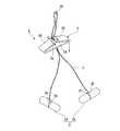
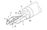
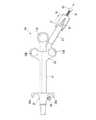
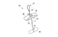
図1及び図2に示すように、図示しない生体組織に係止されるアンカー2、アンカー2から導出された縫合糸3、及び縫合糸3上に配されたストッパ5を備えた本発明の一実施形態に係る縫合具6は、先端に開口部7aが設けられた硬質の針部7Aが配されて内部にアンカー2を収容可能な中空の穿刺針7、及び穿刺針7を進退自在に収納する外側シース8を有するシース9と、穿刺針7内を進退自在に配され、アンカー2に遠位端10aが当接した状態で近位側が手元側まで延びたプッシャ(ワイヤ)10と、外側シース8の基端に接続されて延出された操作部本体11、及び穿刺針7の基端に固着されて操作部本体11に進退自在に配された針スライダ(第一操作部)12を有する操作部14と、プッシャ10の基端に接続されて操作部本体11に対して進退自在に配されたプッシャ操作部(ワイヤ操作部、第二操作部)13と、第一端15aと第二端15bとを有して、第一端15aがプッシャ操作部13に接続されて第二端15bとの間で伸縮するバネ部材(弾性部材)15と、第二端15bに接続され、操作部12に対して移動可能な可動ストッパ(可動部材)16と、可動ストッパ16に配され、可動ストッパ16の操作部12に対する可動状態と固定状態とを切り替えるロック部材(制御部材)17と、を備えた縫合器1とともに使用される。Preferred embodiments according to the present invention will be described in detail below. In the following description, the same components are denoted by the same reference numerals and redundant description is omitted.
As shown in FIGS. 1 and 2, the present invention includes an
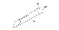
縫合具6のアンカー2は、第一アンカー2A及び第二アンカー2Bを備えている。何れのアンカー2A,2Bも同一形状とされ、円柱形の細長形状を有し、中央部分には周方向に溝2a及び2bがそれぞれ形成されている。縫合糸3は、第一端3aが第一アンカー2Aの溝2a近傍に接続されて延出され、プッシャ10が挿通可能なループ18を途中で形成して折り返されて、第二端3bが第二アンカー2Bの溝2bの近傍に接続されている。 The
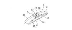
ストッパ5は、図3から図6に示すように、帯状の薄板材の両端側がそれぞれ中央側に向かって折り返されて、基部5Aと一対の折り曲げ片5B,5Cとが形成されている。ストッパ5の基部5Aには、縫合糸3が挿通可能な貫通孔5aが設けられている。一対の折り曲げ片5B,5Cは、基部5Aと略平行になるように配されている。 As shown in FIGS. 3 to 6, the
一対の折り曲げ片5B,5Cのそれぞれの先端には、一対の折り曲げ片5B,5Cの中心軸線Cから互いに離間する方向に偏心した位置に、縫合糸3の挿通方向に厚く形成されて縫合糸3を挟持する厚板部5b,5cが設けられている。厚板部5b,5c間の距離Lは、縫合糸3の径よりも小さくなるように形成されている。 At the tip of each of the pair of
上記偏心によって折り曲げ片5Bの側縁と厚板部5bとの間に形成された隙間S2に向かって突出する係合突部5dが、折り曲げ片5Bと対向する別の折り曲げ片5Cに配された厚板部5cに設けられている。同様に、折り曲げ片5Cの側縁と厚板部5cとの間に形成された隙間S1に向かって突出する係合突部5eが、折り曲げ片5Bに配された厚板部5bに設けられている。 The
このストッパ5は、例えば、板厚0.4mmの帯状の薄板部材の厚板部5b,5cを除いた箇所を厚さ0.2mmまでプレス成形する。その後、両端から所定の長さの部分をそれぞれ中央に向かって折り返して、基部5Aと一対の折り曲げ片5B,5Cとを形成する。又は、図6に示すように、例えば、板厚0.2mmの帯状の薄板部材の端部に、厚さ0.4mmの厚板部20c及び係合突部20dをカシメ又は溶接Wにより固着させてストッパ20としてもよい。 For example, the
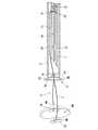
穿刺針7は、針部7Aが先端に接続される管状の手元側部材7Bをさらに備えている。手元側部材7Bは、可撓性を有する軟性部材で構成されている。この手元側部材7Bは、例えば、後述する穿刺針7の外側シース8からの突没に伴う引張・圧縮負荷、及び生体組織の緊縛に伴うストッパ5の縫合糸3上の移動による引張負荷に耐えられるように、PEEK(ポリエーテルエーテルケトン)の押し出し成形管で構成されている。 The
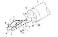
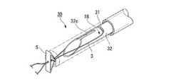
図7から図9に示すように、穿刺針7は、外側シース8とともに後述する内視鏡挿入部EIのチャンネルCH1に挿通される。穿刺針7の先端の開口部7aは、穿刺針7の長手方向に対して傾斜して設けられている。穿刺針7内におけるプッシャ10の先端位置よりも手元側の側面には、穿刺針7の外部から内腔に縫合糸3のループ18が導入される導入孔7bが設けられている。具体的には、第一アンカー2A及び第二アンカー2Bを直列に並べたときの長さよりも開口部7aから離れた位置に設けられている。そして、開口部7aから導入孔7bに向かって縫合糸3が挿通可能な幅のスリット7cが設けられている。 As shown in FIGS. 7 to 9, the
穿刺針7の導入孔7bよりも手元側には、プッシャ10の穿刺針7内における手元側への移動量を規制する規制部材21が径方向内方に突出して設けられている。
規制部材21は、穿刺針7の導入孔7bよりも手元側となる針部7Aの基端に、径方向内方に突出して設けられている。規制部材21は、穿刺針7の先端側の傾斜が鋭く、かつ手元側の傾斜が緩く形成されている。この規制部材21の外周面には雄ネジ部が形成されており、手元側部材7Bの先端には、雄ネジ部と螺合可能な雌ネジ部が形成されている。従って、針部7Aと手元側部材7Bとは、螺合されることにより簡単な構造で高い引張・圧縮負荷に耐える強度で接続される。
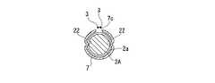
穿刺針7の先端側の内周面には、第一アンカー2A及び第二アンカー2Bを内部に収納した際にそれぞれの溝2aと係合する凸部22が設けられている。On the proximal side of the
The restricting
On the inner peripheral surface on the distal end side of the
プッシャ10は、細長のワイヤとされている。プッシャ10には、縫合具6のアンカー2を穿刺針7に収容した状態でスリット7cから導出された縫合糸3と着脱自在に係合される係合部23が設けられている。係合部23は、プッシャ10の先端側の一部が湾曲して形成されている。 The
外側シース8は、縫合具6を収納した穿刺針7の先端側を覆う先端側シース8Aと、先端側シース8Aの基端に接続されて手元側を覆う手元側シース8Bとを備えている。外側シース8は、金属の素線8aが密にコイル状に巻回されて構成されている。先端側シース8Aのほうが、ストッパ5と穿刺針7とを収納するため手元側シース8Bよりも大きな内径を有している。 The
手元側シース8Bの外表面は、樹脂チューブ24によって被覆されている。樹脂チューブ24は、金属素線8a上に熱収縮により密着固定される。又は、図示しないコイルを芯とした押し出し成形により形成される。なお、樹脂チューブ24の代わりに、樹脂コーティングがなされていても構わない。 The outer surface of the
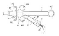
操作部本体11には、図1、図10及び図11に示すように、中心軸線C1方向に対してU字状溝11aが形成されており、基端に指掛部11Aが配されている。操作部本体11の先端側には、針スライダ12の移動を規制する調整ストッパ25が配されている。この調整ストッパ25は、固定ネジ26によって操作部本体11に位置決めされる。調整ストッパ25には、半円形指掛部25Aが設けられている。 As shown in FIGS. 1, 10, and 11, the operation portion
針スライダ12は、U字状溝11aと係合する突出部材12Aを備えて、操作部本体11に進退自在に係合されている。針スライダ12の基端には、中心軸線C1方向に対して傾斜した中心軸線C2方向に延出された分岐部27が、突出部材12Aと接続されて配されている。針スライダ12には、指掛部12Bが二つ配されている。 The
分岐部27には、基端側にプッシャ10の基端側が挿通されたプッシャ貫通孔27aが設けられている。プッシャ貫通孔27aの先端には、穿刺針7の手元側部材7Bの基端が挿通されて、前述した手元側部材7Bの先端の接続と同様に螺合される針固定部27Aが設けられている。分岐部27は円柱状に形成され、可動ストッパ16が進退自在に外嵌されている。 The
プッシャ操作部13は、円柱状に形成され、プッシャ10の基端に接続されている。
バネ部材15は、最大限圧縮された際に、プッシャ10の移動量がアンカー2一つ分の移動量となるように弾性力が調整されている。また、弾性力は、プッシャ10と穿刺針7との摩擦力よりも小さくなるように調整されている。The
The elastic force of the
可動ストッパ16は、有底の円筒状に形成されており、底部16aが、分岐部27の基端27bから所定の距離に離間した状態で、摺動自在に外挿されている。バネ部材15の第二端15bが底部16aに接続されている。
ロック部材17は、可動ストッパ16からプッシャ操作部13の長手方向に突出して、可動ストッパ16を縮径する方向に弾性変形するように設けられている。The
The
この縫合器1は、図12に示すように、内視鏡Eとともに使用される。内視鏡Eは、術者が操作する内視鏡操作部ESと、内視鏡操作部ESから延出された可撓性を有する内視鏡挿入部EIとを備えている。内視鏡挿入部EIには、縫合器1等が挿入されるチャンネルCH1、CH2が内視鏡挿入部EIの先端で開口して設けられている。内視鏡挿入部EIの先端には、照明光学系ELが配されている。 The
次に、縫合器1及び縫合具6の作用について、図13から図43を合わせて縫合方法とともに説明する。なお、管腔器官の一例として胃が示されている。 Next, the operation of the
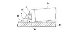
まず、図13に示す状態のストッパ5に対して、図14に示すように、基部5Aの貫通孔5aに縫合糸を挿入し、厚板部5b,5cを離間させる方向に一対の折り曲げ片5B,5Cを変形させながら縫合糸3を挿通する。この際、縫合糸3が基部5Aの方向d1に引っ張られた場合には、厚板部5b,5cも方向d1に移動して、厚板部5b,5c間の距離が縮まり、縫合糸3を締め付けてロックして、縫合糸3の移動を規制する。 First, with respect to the
つまり、アンカー2とストッパ5とを引き離す方向の力が縫合糸3に作用した場合には、一対の折り曲げ片5B,5Cを閉じるように移動させ、縫合糸3の動きをロックするように作用する。即ち、ストッパ5とアンカー2とで挟み込む吻合対象が、ストッパ5を縫合糸3の他端の方向d2に押そうとしても、厚板部5b,5cが縫合糸3を締め付けて縫合糸3に対するストッパ5の位置をロックするので、ストッパ5が方向d2に移動させられることはない。 That is, when a force in the direction of separating the
一方、図15に示すように、ストッパ5をアンカー2に接近させる方向に移動させたとき、即ち、基部5Aと反対の方向d2に縫合糸3が引っ張られた場合には、厚板部5b,5cも方向d2(互いに引き離される方向)に移動させられるので、縫合糸3の締め付けが解除される。つまり、アンカー2とストッパ5とを近付ける方向には縫合糸3の移動を許容するように作用する。即ち、吻合対象にストッパ5を押し付けるとき、つまりストッパ5を縫合糸3の一端の方向d1に移動させるときには、厚板部5b,5c間が開いて縫合糸3への厚板部5b,5cの締め付けが解除される。 On the other hand, as shown in FIG. 15, when the
そして、図16に示すように、吻合対象からの圧力により、ストッパ5が方向d2に強制的に移動させられる。このとき、ストッパ5の基部5Aと一対の折り曲げ片5B,5Cとが略平行状態となる。この状態は、成形時の状態と同じなので、一対の折り曲げ片5B,5Cには曲げ応力がほとんど生じない。従って、吻合対象に対して移動することなく、縫合糸3の締め付け力が維持される。 Then, as shown in FIG. 16, the
次に、図17に示すように、マウスピースMPを装着した患者PTの口から内視鏡挿入部EIを挿入し、内視鏡挿入部EIの先端を湾曲させる。そして、図18に示すように、内視鏡挿入部EIのチャンネルCH1に、例えばスネア等の切開処置具SWを挿入し、病変を含む粘膜M3を切除する。 Next, as shown in FIG. 17, the endoscope insertion portion EI is inserted from the mouth of the patient PT wearing the mouthpiece MP, and the tip of the endoscope insertion portion EI is bent. Then, as shown in FIG. 18, an incision treatment tool SW such as a snare is inserted into the channel CH1 of the endoscope insertion portion EI, and the mucous membrane M3 including the lesion is excised.
一方、図19に示すように、縫合具6の第一アンカー2A及び第二アンカー2Bを穿刺針7内に直列に収納して、凸部22と第一アンカー2Aの溝2aとを係合する。そして、スリット7cから縫合糸3が突出するようにして、ループ18を導入孔7bから再び穿刺針7内に導入する。さらに、ループ18をプッシャ10に挿通して係合部23に係合させ、ストッパ5を穿刺針7内に収容した状態としておく。 On the other hand, as shown in FIG. 19, the
粘膜M3を切除した後、切開処置具SWの代わりに縫合器1をチャンネルCH1に挿入して、チャンネルCH1の先端から外側シース8の先端を突出させる。
この状態から図20に示すように、針スライダ12を操作部本体11に対して前進させ、図21に示すように、穿刺針7を外側シース8から突出させる。このとき、指掛部11Aに親指を、かつ、指掛部12Bに人差し指、中指、或いは薬指の何れか一つを通し、両者を開く操作により針スライダ12を前方に移動させる。または、指掛部12Bに親指を、かつ、半円形指掛部25Aに人差し指、中指、或いは薬指の何れかを係合し、握りこむ操作により針スライダ12を前方に移動させてもよい。握りこむ操作のほうが、開く操作よりも微妙な調整を行うことができ、力もかけやすいので、穿刺針7の外側シース8からの突出量、速度の調整が可能となる。After excising the mucous membrane M3, the
From this state, as shown in FIG. 20, the
次に、図22に示すように、チャンネルCH2に鉗子Fを挿入して先端から突出させ、図23に示すように、粘膜欠損部M4の奥側の断端M5を把持し、粘膜欠損部M4から離れる方向に牽引、挙上させる。
この状態で、穿刺針7の穿刺方向を規定するために、図24に示すように、内視鏡挿入部EIを湾曲させる。このとき、穿刺針7の手元側部材7Bは軟性のチューブから構成されているので、プッシャ10を軸とした外側部分が湾曲方向に伸ばされる。一方、プッシャ10は剛性が高く、小径のワイヤなので湾曲に伴う伸縮がない。そのため、穿刺針7内の規制部材21にプッシャ10の係合部23が引っ掛かり、相対的にプッシャ操作部13が可動ストッパ16とともに分岐部27側に引き込まれる。Next, as shown in FIG. 22, the forceps F is inserted into the channel CH2 so as to protrude from the distal end, and as shown in FIG. Tow and lift in the direction away from.
In this state, in order to define the puncture direction of the
その後、調整ストッパ25に当接するまで、針スライダ12を操作部本体11に対して前進させ、穿刺針7を外側シース8の先端から突出させる。こうして、図25に示すように、縫合器1の全体、或いは内視鏡挿入部EIを前進させることにより、鉗子Fと内視鏡の操作とにより挙上された粘膜M5に穿刺針7を貫通する。 Thereafter, the
次に、図26に示すように、可動ストッパ16のロック部材17を分岐部27とともに把持し、可動ストッパ16と分岐部27とを固定させる。そして、図27に示すように、プッシャ操作部13を先端側に移動してバネ部材15を圧縮する。このとき、プッシャ10が穿刺針7に対して、アンカー1個分の長さだけ移動する。そのため、凸部22と第一アンカー2Aの溝2aとの係合が解除され、図28に示すように、第二アンカー2Bが前進し、面接触している第一アンカー2Aが穿刺針7の先端に向かって押し出される。そして、第二アンカー2Bの溝2bと凸部22とが新たに係合される。この結果、第一アンカー2Aが粘膜M5の裏側に脱落する。そして、穿刺針7が粘膜M5から引き抜かれる際に、縫合糸3が粘膜M5を貫通し、アンカー2Aが粘膜欠損部M4の奥側に留置される。 Next, as shown in FIG. 26, the
続いて、ロック部材17を手放して可動ストッパ16をもとの形状に復元させる。ここで、バネ部材15の弾性復元力が、プッシャ10と穿刺針7との全長にわたって発生する摩擦力よりも小さく設定されている。従って、プッシャ10と穿刺針7との相対移動がない状態で、バネ部材15が元の長さに復元する間、図29に示すように、可動ストッパ16が分岐部27に対して前進する。 Subsequently, the
次に、第二アンカー2Bを留置する場所に内視鏡挿入部EIの先端を移動する。そして、第一アンカー7Aと同様に、図30に示すように、粘膜欠損部M4を挟んで粘膜M5の略対称位置となる手前側の粘膜M6の端部を鉗子Fで把持して挙上する。再び穿刺針7を外側シース8の先端から突出させたまま、縫合器1の全体、或いは内視鏡挿入部EIを前進させることにより、挙上された粘膜M6に穿刺針7を貫通する。 Next, the distal end of the endoscope insertion portion EI is moved to a place where the
ここで、図31に示すように、ロック部材17を再び把持して変形させ、分岐部27に当接させる。そして、図32に示すように、プッシャ操作部13を可動ストッパ16に対して移動して、バネ部材15を圧縮する。これにより、図33に示すように、凸部22と第二アンカー2Bの溝2bとの係合が解除され、第二アンカー2Bが粘膜M6の裏側に放出される。穿刺針7が粘膜M6から引き抜かれると、縫合糸3が粘膜M6を貫通し、図34に示すように、第二アンカー2Bが粘膜欠損部M4の手前側に留置される。 Here, as shown in FIG. 31, the
次に、図35に示すように、針スライダ12を操作部本体11に対して手元側に後退する。これにより、穿刺針7が相対的に外側シース8内に引き込まれ、図36に示すように、外側シース8の先端が縫合具6のストッパ5に当接する。さらに、図37に示すように、針スライダ12を手元側に移動することにより、ストッパ5とアンカー2との距離が縮まり、かつ、アンカー2A,2Bの距離が縮まることにより、アンカー2A,2Bに係止された粘膜M5,M6が引き寄せられる。最後は、図38に示すように、ストッパ5が粘膜M5,M6に当接して締め付けられ、粘膜欠損部M4が縮小される。 Next, as shown in FIG. 35, the
そして、図39に示すように、可動ストッパ16を分岐部27に対して手元側に後退させる。このとき、図40及び図41に示すように、プッシャ10の係合部23から縫合糸3のループ18が外れるとともに、係合部23が弾性変形して規制部材21を乗り越えてプッシャ10が穿刺針7に対して手元側に移動する。ここで、縫合器1、或いは内視鏡挿入部EIを粘膜欠損部M4から離れるように後退させると、図42に示すように、穿刺針7の導入孔7bからループ18が穿刺針7の外側に引っ張られる。こうして、図43に示すように、縫合糸3が緩まないようにストッパ5で保持された状態で、縫合器1と縫合具6とが分離され、縫合具6が留置される。 Then, as shown in FIG. 39, the
この縫合器1によれば、可動ストッパ16を可動状態とし、かつ、バネ部材15を伸長状態とすることにより、シース9を湾曲させた際にも、シース9の伸縮に合わせてプッシャ操作部13を操作部本体11に対して移動させることができる。また、ロック部材17により、可動ストッパ16を固定状態とし、かつ、バネ部材15を収縮状態とすることにより、シース9に対してプッシャ10の先端10aの位置を一定量だけ移動させることができる。従って、シース9の湾曲前後にかかわらず、簡易な操作でシース9に対してプッシャ10を一定量だけ精度よく進退させることができる。
この際、ロック部材17を把持して分岐部27に当接させることにより、可動ストッパ16を操作部本体11に対して固定した状態とすることができる。一方、ロック部材17を変形させない場合には、可動ストッパ16を分岐部27に対して可動状態とすることができる。According to the
At this time, the
また、可動ストッパ16と分岐部27とがバネ部材15で接続されているので、バネ部材15の伸縮量を容易に規定することができ、精度よくプッシャ10を進退させることができる。 Further, since the
さらに、プッシャ10に係合部23が配されているので、穿刺針7を生体組織に穿刺し、プッシャ10を移動してアンカー2を留置した後でも、縫合糸3をプッシャに係合させ続けることができる。そのため、外側シース8を縫合具6のストッパ5に当接した状態で穿刺針7をプッシャ10とともに外側シース8の手元側に引き込むことにより、ストッパ5をアンカー2側に移動することができる。また、その後に縫合糸3とプッシャ10との係合を解除することにより、縫合具6を生体組織に留置することができる。従って、複数の処置具を入れ替えることなく、縫合具6の留置と縫合とを続けて行うことができる。
この際、縫合糸3のループ18を穿刺針7の導入孔7bから穿刺針7内に導入し、プッシャ10をループ18に挿通することによって、ループ18を係合部23に容易に係合させることができる。Further, since the engaging
At this time, the
また、針スライダ12を操作部本体11に対して進退移動させることにより、外側シース8に対して穿刺針7を突没させることができる。また、プッシャ操作部13を針スライダ12に対して進退移動させることにより、穿刺針7に対してプッシャ10を進退させることができる。このとき、操作部本体11に対して分岐部27が傾斜して設けられているので、針スライダ12とプッシャ操作部13との進退操作をする際、持ち替えることなく両者を続けて操作することができる。 Further, the
また、外側シース8がコイル状に形成されているので、縫合糸3を係合部23に係合させた状態で穿刺針7を外側シース8内に没入させて、縫合糸3のストッパ5を外側シース8の先端で押圧しても、外側シース8の軸方向に生じる圧縮力に好適に耐えることができる。 Further, since the
また、手元側シース8Bには樹脂チューブ24が嵌合されているので、外側シース8に対して穿刺針7を押し出す際に外側シース8に生じる引張力に好適に耐えることができる。 Further, since the
また、図41に示すように、穿刺針7に規制部材21が設けられているので、組み立て時にプッシャ10を穿刺針7内に挿入する際には、手元側の傾斜の緩い部分にプッシャ10を当接しながら挿入でき、容易に組み立てを行うことができる。一方、組み立て後に、プッシャ10が穿刺針7の基端側に不用意に相対移動しようとしても、係合部23が規制部材21の傾斜の鋭い部分に当接するので、それ以上の移動を規制することができる。 As shown in FIG. 41, since the
また、この縫合具6によれば、縫合具6の一対の折り曲げ片5B,5Cの先端の厚板部5b,5cで縫合糸3を挟持させた際、一対の折り曲げ片5B,5Cと縫合糸3との接触面積をより好適に増大させ、一対の折り曲げ片5B,5Cに生じる応力を小さくすることができる。従って、生体組織に対してストッパ5の安定した固定力を維持することができる。 Further, according to the
また、縫合糸3をストッパ5に挿通させたときには、基部5Aに対して一対の折り曲げ片5B,5Cが傾斜した状態となるが、縫合糸3に対してストッパ5を移動して生体組織に固定させたときには、一対の折り曲げ片5B,5Cと基部5Aとが再び初期加工時の略平行状態となる。即ち、一対の折り曲げ片5B,5Cが初期加工時に戻るだけなので、ストッパ5を移動させる間、縫合糸3を固定する力は緩まない。その結果、留置されている間に縫合糸3に対する折り曲げ片5B,5Cの移動を好適に抑えることができる。 When the
また、ストッパ5で縫合糸3を挟持する際、厚板部5b,5c及び係合突部5d,5eが係合されるので、一対の折り曲げ片5B,5Cの中心軸線Cに対して交差する方向の力に対する折り曲げ片5B,5C同士のずれを好適に抑えることができる。 Further, when the
なお、図44から図47に示すように、穿刺針28の導入孔28bが設けられた部分が偏心して隆起部28Aが形成されたものでも構わない。これは、外側シース8内に穿刺針28が配された際に、外側シース8の中心軸線C3と穿刺針28の中心軸線C4とが偏心した状態となるため、穿刺針28との間に空間Sが形成された分を利用したものである。 As shown in FIGS. 44 to 47, the portion provided with the
また、図48に示すように、縫合器30の係合部31が、穿刺針32の側面にスリット状に設けられているとしてもよい。
この縫合器30は、縫合具6の第一アンカー2A及び第二アンカー2Bを穿刺針32内に直列に収納して、スリット32cから縫合糸3を突出させた後、そのままループ18を係合部31に係合させ、ストッパ5を穿刺針32内に収容した状態としておく。
そして、第1の実施形態と同様の操作によって、縫合具6の図示しないアンカーを留置する。縫合糸3を係合部31から取り外す際には、穿刺針32を一端、外側シース8から突出させ、穿刺針32を揺動する。そのとき、図49に示すように、縫合糸3が係合部31から離脱する。Further, as shown in FIG. 48, the engaging
The
Then, an anchor (not shown) of the
この縫合器30によれば、係合部31がスリット状に形成されているので、縫合糸3の一部を引っ掛けることにより、穿刺針32の表面にループ18を容易に係合させることができる。 According to the
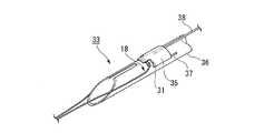
また、図50に示すように、縫合器33が、係合部31を覆う蓋35を備えていてもよい。この蓋35は、穿刺針36の表面に設けられたガイド溝37に係合され、ガイド溝37に沿って移動するように牽引部材38が接続されている。 Further, as shown in FIG. 50, the
この縫合器33によれば、ループ18を係合部31に係合させた後に蓋35で覆うことにより、縫合糸3が係合部31から間違って離脱してしまうのを好適に抑えることができる。また、牽引部材38を牽引して蓋35を移動することにより、ループ18を係合部31から容易に外すことができる。 According to the
また、図51に示すように、縫合器40の係合部41が、穿刺針42の側面に突出して設けられているとしてもよい。
この縫合器40も、ループ18を係合部41に係合させ、図示しないアンカーを留置する。縫合糸3を係合部41から取り外す際には、穿刺針42を一端、外側シース8から突出し、穿刺針42を揺動しながら縫合糸3を係合部41から離脱させる。In addition, as shown in FIG. 51, the engaging
The
この縫合器40によれば、係合部41が突出して設けられているので、穿刺針42の表面に縫合糸3のループ18を容易に係合させることができる。 According to the
また、図52に示すように、縫合器45における縫合糸3を切断可能な刃46が、プッシャ10に設けられているとしてもよい。
ここで、刃46は、係合部23よりもプッシャ10の先端側であって、導入孔7bと規制部材21との距離よりも短い距離に配されている。刃面46aは、手元側にのみ設けられている。52, the
Here, the
この縫合器45は、第1の実施形態と同様の操作によって、縫合具6の第一アンカー2A及び第二アンカー2Bを穿刺針7内に直列に収納して、スリット7cから縫合糸3を突出させた後、ループ18を導入孔7bから穿刺針7内に導入し、ストッパ5の先端に挿通して係合部23に係合させる。ここで刃面46aが手元側に配されているので、ループ18の係合時にはループ18は刃46によって切断されない。 The
縫合糸3を係合部23から取り外す際には、穿刺針7に対してプッシャ10を手元側に引き込む。この際、ループ18が刃面46aに当接するので、ループ18が切断され、縫合糸3が係合部23から離脱する。 When removing the
この縫合器45によれば、縫合糸3のループ18を挿通させる際とは異なる方向にプッシャ10を相対移動させることにより、ループ18を刃46で容易に切断して係合を解除することができる。 According to the
また、図53に示すように、縫合具47が一つのアンカー48のみを有する場合には、縫合糸3の第一端3a及び第二端3bがともにアンカー48の同一箇所に接続されたものでも構わない。 53, when the suture instrument 47 has only one
また、図54に示すように、縫合糸3の第一端3aがアンカー48に接続され、ループ18の代わりに第二端3bにリング50が配された縫合具51であっても構わない。 As shown in FIG. 54, a
また、図55に示すように、縫合糸52の第二端が予めループ18に成形された縫合具53でもよい。また、図56に示すように、縫合糸3が折り返されて第二端3bが縫合糸3の途中に結び付けられて結び目55が形成され、ループ18が形成された縫合具56、又は、図57に示すように、カシメ部材57によってかしめられてループ18が形成された縫合具58でも構わない。 Further, as shown in FIG. 55, a
以上、本発明の好ましい実施例を説明したが、本発明はこれら実施例に限定されることはない。本発明の趣旨を逸脱しない範囲で、構成の付加、省略、置換、およびその他の変更が可能である。本発明は前述した説明によって限定されることはなく、添付のクレームの範囲によってのみ限定される。 The preferred embodiments of the present invention have been described above, but the present invention is not limited to these embodiments. Additions, omissions, substitutions, and other modifications can be made without departing from the spirit of the present invention. The present invention is not limited by the above description, but only by the scope of the appended claims.
2、48 アンカー(係止部材)
3、52 縫合糸
5 ストッパ(固定部材)
5A 基部
5a 貫通孔
5B、5C 折り曲げ片
5b、5c 厚板部
5d、5e 係合突部
6、47、51、56、58 縫合具
C 中心軸線2, 48 anchor (locking member)
3, 52
Claims (4)
Translated fromJapanese前記固定部材が、細長板状に形成されて前記縫合糸が貫通する貫通孔が配された基部と、
該基部の両端がそれぞれ中央側に向かって折り返されるようにして互いの端部が対向するように形成された一対の折り曲げ片と、
を備え、
前記縫合糸の挿通方向に厚く形成されて前記縫合糸を挟持する厚板部が、前記一対の折り曲げ片のそれぞれの先端に設けられている。A locking member placed in the living tissue, a suture led out from the locking member, and a fixing that is inserted into the suture and regulates the displacement of the suture with respect to the biological tissue anastomosed by the suture. A suturing tool comprising a member,
A base portion in which the fixing member is formed in an elongated plate shape and a through-hole through which the suture thread passes is disposed;
A pair of bent pieces formed such that both ends of the base portion are folded toward the center side so that the end portions face each other;
With
A thick plate portion that is formed thick in the insertion direction of the suture and sandwiches the suture is provided at the tip of each of the pair of bent pieces.
前記一対の折り曲げ片の中心軸線から互いに離間する方向に偏心して前記厚板部がそれぞれ設けられ、
前記偏心によって前記折り曲げ片の側縁と前記厚板部との間に形成された隙間に向かって突出する係合突部が、前記折り曲げ片と対向する別の折り曲げ片に配された厚板部に設けられている。The suturing device according to claim 1,
The thick plate portions are each provided eccentrically in a direction away from the central axis of the pair of bent pieces,
A thick plate portion in which an engaging protrusion that protrudes toward a gap formed between a side edge of the bent piece and the thick plate portion due to the eccentricity is disposed on another bent piece facing the bent piece. Is provided.
Applications Claiming Priority (2)
| Application Number | Priority Date | Filing Date | Title |
|---|---|---|---|
| US11/711,265US7780702B2 (en) | 2007-02-27 | 2007-02-27 | Suture tool |
| US11/711,265 | 2007-02-27 |
Publications (2)
| Publication Number | Publication Date |
|---|---|
| JP2008206972Atrue JP2008206972A (en) | 2008-09-11 |
| JP5259201B2 JP5259201B2 (en) | 2013-08-07 |
Family
ID=39535144
Family Applications (1)
| Application Number | Title | Priority Date | Filing Date |
|---|---|---|---|
| JP2008014120AExpired - Fee RelatedJP5259201B2 (en) | 2007-02-27 | 2008-01-24 | Suture tool |
Country Status (4)
| Country | Link |
|---|---|
| US (1) | US7780702B2 (en) |
| EP (1) | EP1964520B1 (en) |
| JP (1) | JP5259201B2 (en) |
| DE (1) | DE602007012996D1 (en) |
Cited By (1)
| Publication number | Priority date | Publication date | Assignee | Title |
|---|---|---|---|---|
| WO2011126050A1 (en)* | 2010-04-06 | 2011-10-13 | 日立化成工業株式会社 | Polymer molded body for pulling biological tissue, medical pulling member using same, and medical pulling tool |
Families Citing this family (41)
| Publication number | Priority date | Publication date | Assignee | Title |
|---|---|---|---|---|
| US7887551B2 (en) | 1999-12-02 | 2011-02-15 | Smith & Nephew, Inc. | Soft tissue attachment and repair |
| ATE514382T1 (en) | 2006-11-30 | 2011-07-15 | Wilson Cook Medical Inc | FABRIC ANCHOR FOR SEAM CLOSURE OF PERFORATIONS |
| US9155532B2 (en)* | 2007-05-25 | 2015-10-13 | Cook Medical Technologies Llc | Medical devices, systems and methods for closing perforations |
| US8740937B2 (en) | 2007-05-31 | 2014-06-03 | Cook Medical Technologies Llc | Suture lock |
| JP5226792B2 (en)* | 2007-09-25 | 2013-07-03 | クック メディカル テクノロジーズ エルエルシー | Medical instruments, devices and methods for using tissue anchors |
| WO2009082596A1 (en)* | 2007-12-18 | 2009-07-02 | Wilson-Cook Medical, Inc. | Device and method for placement of tissue anchors |
| WO2010022060A1 (en) | 2008-08-19 | 2010-02-25 | Wilson-Cook Medical Inc. | Apparatus for removing lymph nodes or anchoring into tissue during a translumenal procedure |
| US8192461B2 (en) | 2008-09-11 | 2012-06-05 | Cook Medical Technologies Llc | Methods for facilitating closure of a bodily opening using one or more tacking devices |
| WO2010042402A1 (en)* | 2008-10-06 | 2010-04-15 | Wilson-Cook Medical, Inc. | Endcap for safely deploying tissue anchors |
| CN103705280B (en) | 2008-11-26 | 2017-11-14 | 史密夫和内修有限公司 | Tissue repair device |
| US8377095B2 (en)* | 2008-12-05 | 2013-02-19 | Cook Medical Technologies, LLC | Tissue anchors for purse-string closure of perforations |
| AU2009324819B2 (en) | 2008-12-09 | 2014-04-17 | Cook Medical Technologies Llc | Retractable tacking device |
| EP2389122B1 (en) | 2008-12-19 | 2015-03-04 | Cook Medical Technologies LLC | Clip devices |
| CA2757554A1 (en) | 2009-04-03 | 2010-10-07 | Cook Medical Technologies Llc | Tissue anchors and medical devices for rapid deployment of tissue anchors |
| EP2413809B1 (en) | 2009-04-03 | 2014-10-08 | Cook Medical Technologies LLC | Medical devices for rapid deployment and fixation of tissue anchors |
| JP2012527970A (en) | 2009-05-28 | 2012-11-12 | クック メディカル テクノロジーズ エルエルシー | Hail-fastening device and hail-fastening device deployment method |
| US8814903B2 (en) | 2009-07-24 | 2014-08-26 | Depuy Mitek, Llc | Methods and devices for repairing meniscal tissue |
| US8828053B2 (en) | 2009-07-24 | 2014-09-09 | Depuy Mitek, Llc | Methods and devices for repairing and anchoring damaged tissue |
| US9980708B2 (en) | 2010-01-20 | 2018-05-29 | Micro Interventional Devices, Inc. | Tissue closure device and method |
| US20110178537A1 (en)* | 2010-01-20 | 2011-07-21 | Whitman Michael P | Tissue repair implant and delivery device and method |
| US10058314B2 (en) | 2010-01-20 | 2018-08-28 | Micro Interventional Devices, Inc. | Tissue closure device and method |
| US10959840B2 (en) | 2010-01-20 | 2021-03-30 | Micro Interventional Devices, Inc. | Systems and methods for affixing a prosthesis to tissue |
| US10743854B2 (en) | 2010-01-20 | 2020-08-18 | Micro Interventional Devices, Inc. | Tissue closure device and method |
| US8475525B2 (en) | 2010-01-22 | 2013-07-02 | 4Tech Inc. | Tricuspid valve repair using tension |
| US20110218191A1 (en)* | 2010-03-03 | 2011-09-08 | Boehringer Ingelheim Vetmedica Gmbh | Use of meloxicam for the long term-treatment of kidney disorders in cats |
| US9597064B2 (en) | 2010-04-27 | 2017-03-21 | DePuy Synthes Products, Inc. | Methods for approximating a tissue defect using an anchor assembly |
| CA2797607A1 (en) | 2010-04-27 | 2011-11-03 | Synthes Usa, Llc | Anchor assembly including expandable anchor |
| US9743919B2 (en) | 2010-04-27 | 2017-08-29 | DePuy Synthes Products, Inc. | Stitch lock for attaching two or more structures |
| US9451938B2 (en) | 2010-04-27 | 2016-09-27 | DePuy Synthes Products, Inc. | Insertion instrument for anchor assembly |
| AU2011354723B2 (en)* | 2011-01-14 | 2016-07-28 | Synthes Gmbh | Stitch lock for attaching two or more structures |
| US10022114B2 (en)* | 2013-10-30 | 2018-07-17 | 4Tech Inc. | Percutaneous tether locking |
| US10085735B2 (en)* | 2014-10-29 | 2018-10-02 | Smith & Nephew, Inc. | Modular tissue repair kit and devices and method related thereto |
| US20170273680A1 (en) | 2016-02-01 | 2017-09-28 | DePuy Synthes Products, Inc. | Tissue augmentation tacks for use with soft tissue fixation repair systems and methods |
| US11523812B2 (en) | 2016-02-01 | 2022-12-13 | Medos International Sarl | Soft tissue fixation repair methods using tissue augmentation constructs |
| US11484401B2 (en) | 2016-02-01 | 2022-11-01 | Medos International Sarl | Tissue augmentation scaffolds for use in soft tissue fixation repair |
| WO2018089838A1 (en)* | 2016-11-11 | 2018-05-17 | Tack Surgical, LLC | Tissue fixation and closure suture articles and suture placement devices |
| WO2018087769A1 (en) | 2016-11-13 | 2018-05-17 | Anchora Medical Ltd. | Minimally-invasive tissue suturing device |
| AU2018203301B2 (en)* | 2017-06-09 | 2024-02-08 | Medos International Sarl | Tissue augmentation tacks for use with soft tissue fixation repair systems and methods |
| US11375994B2 (en)* | 2019-07-12 | 2022-07-05 | Abbot Cardiovascular Systems, Inc. | Methods, systems, and devices for positioning sutures for closing an opening in tissue |
| WO2021165945A2 (en)* | 2020-02-20 | 2021-08-26 | Palliare Limited | A suturing device |
| USD977639S1 (en) | 2020-11-20 | 2023-02-07 | Palliare Limited | Suture |
Citations (4)
| Publication number | Priority date | Publication date | Assignee | Title |
|---|---|---|---|---|
| JP2000225118A (en)* | 1998-12-30 | 2000-08-15 | Depuy Orthopaedics Inc | Suture fixing tool |
| JP2002191608A (en)* | 2000-11-03 | 2002-07-09 | Radi Medical Systems Ab | Closure apparatus and wound occlusion apparatus |
| JP2006239455A (en)* | 2006-06-01 | 2006-09-14 | Olympus Corp | Suturing instrument |
| JP2007536007A (en)* | 2004-05-07 | 2007-12-13 | ユーエスジーアイ メディカル, インコーポレイテッド | Apparatus and method for placing and securing an anchor |
Family Cites Families (15)
| Publication number | Priority date | Publication date | Assignee | Title |
|---|---|---|---|---|
| US2583530A (en)* | 1947-01-30 | 1952-01-29 | Ericsson Telefon Ab L M | Electrical connecting terminal strap |
| US3673640A (en)* | 1971-01-13 | 1972-07-04 | Dwight C Brown | Bag closure |
| US4217902A (en)* | 1977-05-02 | 1980-08-19 | March Alfred L | Hemostatic clip |
| AU8984282A (en) | 1981-11-11 | 1983-05-19 | Fritz Gegauf A.G. Bernina-Nahmaschinenfabrik | Implements to aid suturing |
| CH687060A5 (en)* | 1994-02-11 | 1996-09-13 | Alice Walder Utz Dr | Piece surgical clip. |
| US6099553A (en)* | 1998-05-21 | 2000-08-08 | Applied Medical Resources Corporation | Suture clinch |
| US6648903B1 (en)* | 1998-09-08 | 2003-11-18 | Pierson, Iii Raymond H. | Medical tensioning system |
| US6165204A (en) | 1999-06-11 | 2000-12-26 | Scion International, Inc. | Shaped suture clip, appliance and method therefor |
| DE60120155T2 (en) | 2001-09-10 | 2006-10-26 | Thermocore Medical Systems Nv | Arrangement for positioning catheters |
| US20040236372A1 (en)* | 2003-05-20 | 2004-11-25 | Anspach William E. | Suture clamp |
| JP4166632B2 (en) | 2003-06-06 | 2008-10-15 | オリンパス株式会社 | Suture device |
| US8951285B2 (en) | 2005-07-05 | 2015-02-10 | Mitralign, Inc. | Tissue anchor, anchoring system and methods of using the same |
| US7875041B2 (en) | 2005-09-28 | 2011-01-25 | Olympus Medical Systems Corp. | Suturing method for penetrating hole |
| US7896895B2 (en)* | 2005-11-23 | 2011-03-01 | Ethicon Endo-Surgery, Inc. | Surgical clip and applier device and method of use |
| EP2032044A2 (en)* | 2006-05-25 | 2009-03-11 | Mitralign, Inc. | Lockers for surgical tensioning members and methods of using the same to secure surgical tensioning members |
- 2007
- 2007-02-27USUS11/711,265patent/US7780702B2/enactiveActive
- 2007-11-27DEDE602007012996Tpatent/DE602007012996D1/enactiveActive
- 2007-11-27EPEP07022958Apatent/EP1964520B1/ennot_activeNot-in-force
- 2008
- 2008-01-24JPJP2008014120Apatent/JP5259201B2/ennot_activeExpired - Fee Related
Patent Citations (4)
| Publication number | Priority date | Publication date | Assignee | Title |
|---|---|---|---|---|
| JP2000225118A (en)* | 1998-12-30 | 2000-08-15 | Depuy Orthopaedics Inc | Suture fixing tool |
| JP2002191608A (en)* | 2000-11-03 | 2002-07-09 | Radi Medical Systems Ab | Closure apparatus and wound occlusion apparatus |
| JP2007536007A (en)* | 2004-05-07 | 2007-12-13 | ユーエスジーアイ メディカル, インコーポレイテッド | Apparatus and method for placing and securing an anchor |
| JP2006239455A (en)* | 2006-06-01 | 2006-09-14 | Olympus Corp | Suturing instrument |
Cited By (3)
| Publication number | Priority date | Publication date | Assignee | Title |
|---|---|---|---|---|
| WO2011126050A1 (en)* | 2010-04-06 | 2011-10-13 | 日立化成工業株式会社 | Polymer molded body for pulling biological tissue, medical pulling member using same, and medical pulling tool |
| JP5771602B2 (en)* | 2010-04-06 | 2015-09-02 | 日立化成株式会社 | Polymer molded body for pulling biological tissue, medical pulling member and medical puller using the same |
| US9579092B2 (en) | 2010-04-06 | 2017-02-28 | Kazutoshi Kobayashi | Polymer molded body for pulling biological tissue, medical pulling member using same, and medical pulling tool |
Also Published As
| Publication number | Publication date |
|---|---|
| US20080208218A1 (en) | 2008-08-28 |
| EP1964520B1 (en) | 2011-03-09 |
| JP5259201B2 (en) | 2013-08-07 |
| US7780702B2 (en) | 2010-08-24 |
| EP1964520A3 (en) | 2009-01-07 |
| EP1964520A2 (en) | 2008-09-03 |
| DE602007012996D1 (en) | 2011-04-21 |
Similar Documents
| Publication | Publication Date | Title |
|---|---|---|
| JP5259201B2 (en) | Suture tool | |
| JP5242181B2 (en) | Suture device | |
| US8308766B2 (en) | Endoscopic treatment instrument | |
| US10143470B2 (en) | Tissue-fastening tool indwelling device | |
| EP1844718B1 (en) | Medical suture and ligature instrument and medical suture and ligature tool | |
| JP6084346B1 (en) | Clip device | |
| US10485532B2 (en) | Suture passer device including a blunt tip and a sharp tip | |
| US8911454B2 (en) | Suturing device | |
| US20080243148A1 (en) | Suture instrument | |
| US20060004409A1 (en) | Devices for locking and/or cutting a suture | |
| US20050216036A1 (en) | Endoscopic fastening system with multiple fasteners | |
| JP2007029195A (en) | Pressing member, endoscope treatment system and suturing apparatus for endoscope | |
| US20090005792A1 (en) | Medical Suturing and Ligating Apparatus | |
| JP2007524425A (en) | Expandable needle suturing device and associated handle assembly | |
| US20170035413A1 (en) | Suture-fixing system | |
| JP2008049198A (en) | Clip device of biological tissue | |
| US12150643B2 (en) | Endoscopic treatment device | |
| US12357300B2 (en) | Needle holder for endoscope and operating method of suture needle | |
| US12402878B2 (en) | Systems, devices, and related methods for fastening tissue | |
| US20220133290A1 (en) | Endoscopic treatment device, and usage method thereof | |
| JP5317680B2 (en) | Endoscopic suture instrument |
Legal Events
| Date | Code | Title | Description |
|---|---|---|---|
| A621 | Written request for application examination | Free format text:JAPANESE INTERMEDIATE CODE: A621 Effective date:20101006 | |
| A977 | Report on retrieval | Free format text:JAPANESE INTERMEDIATE CODE: A971007 Effective date:20120706 | |
| A131 | Notification of reasons for refusal | Free format text:JAPANESE INTERMEDIATE CODE: A131 Effective date:20120717 | |
| A521 | Request for written amendment filed | Free format text:JAPANESE INTERMEDIATE CODE: A821 Effective date:20120911 Free format text:JAPANESE INTERMEDIATE CODE: A523 Effective date:20120911 | |
| TRDD | Decision of grant or rejection written | ||
| A01 | Written decision to grant a patent or to grant a registration (utility model) | Free format text:JAPANESE INTERMEDIATE CODE: A01 Effective date:20130326 | |
| A61 | First payment of annual fees (during grant procedure) | Free format text:JAPANESE INTERMEDIATE CODE: A61 Effective date:20130424 | |
| FPAY | Renewal fee payment (event date is renewal date of database) | Free format text:PAYMENT UNTIL: 20160502 Year of fee payment:3 | |
| R151 | Written notification of patent or utility model registration | Ref document number:5259201 Country of ref document:JP Free format text:JAPANESE INTERMEDIATE CODE: R151 | |
| S111 | Request for change of ownership or part of ownership | Free format text:JAPANESE INTERMEDIATE CODE: R313111 | |
| R350 | Written notification of registration of transfer | Free format text:JAPANESE INTERMEDIATE CODE: R350 | |
| S531 | Written request for registration of change of domicile | Free format text:JAPANESE INTERMEDIATE CODE: R313531 | |
| R350 | Written notification of registration of transfer | Free format text:JAPANESE INTERMEDIATE CODE: R350 | |
| R250 | Receipt of annual fees | Free format text:JAPANESE INTERMEDIATE CODE: R250 | |
| R250 | Receipt of annual fees | Free format text:JAPANESE INTERMEDIATE CODE: R250 | |
| R250 | Receipt of annual fees | Free format text:JAPANESE INTERMEDIATE CODE: R250 | |
| LAPS | Cancellation because of no payment of annual fees |