JP2008206789A - Fixture and fixture set - Google Patents
Fixture and fixture setDownload PDFInfo
- Publication number
- JP2008206789A JP2008206789AJP2007047155AJP2007047155AJP2008206789AJP 2008206789 AJP2008206789 AJP 2008206789AJP 2007047155 AJP2007047155 AJP 2007047155AJP 2007047155 AJP2007047155 AJP 2007047155AJP 2008206789 AJP2008206789 AJP 2008206789A
- Authority
- JP
- Japan
- Prior art keywords
- plate member
- fracture piece
- mounting strip
- head
- notch
- Prior art date
- Legal status (The legal status is an assumption and is not a legal conclusion. Google has not performed a legal analysis and makes no representation as to the accuracy of the status listed.)
- Granted
Links
Images


Landscapes
- Surgical Instruments (AREA)
Abstract
Translated fromJapaneseDescription
Translated fromJapanese本発明は、骨折片を所要の整復姿勢で固定するための固定具及び固定具セットに関する。 The present invention relates to a fixture and a fixture set for fixing a fracture piece in a required reduction posture.
例えば橈骨遠位部が骨折した場合、金属材を帯板状に成形してなるプレート部材の一端側を骨折した橈骨遠位部に螺子・釘といった取付用条材にて取り付けた後、当該橈骨遠位部を所要の姿勢に整復し、次いで前記プレート部材の他端側を橈骨本体に取付用条材にて取り付けることによって、骨折した橈骨遠位部を整復姿勢で固定している。
このようなプレート部材と取付用条材とを備える固定具として、後記する特許文献1には次のようなものが開示されている。For example, when the distal part of the rib is fractured, after attaching one end side of the plate member formed by molding a metal material into a band plate to the distal part of the fractured bone with an attachment strip such as a screw or nail, the rib The distal portion is reduced to a required posture, and then the other end side of the plate member is attached to the rib main body with a mounting strip, thereby fixing the fractured distal portion of the rib in the reduced posture.
As a fixture including such a plate member and a mounting strip, Patent Document 1 described below discloses the following.
すなわち、帯板状のプレート部材の一端側は平面視が略舌片形になしてあり、この一端部の周縁部に取付用条材を挿通させる複数の挿通孔が、プレート部材を貫通する様態で一端部の周方向へ適宜の距離を隔てて開設してある。また、プレート部材の他端側には複数の挿通孔が、プレート部材の略中心軸上に適宜の間隔で開設してある。 That is, the one end side of the strip plate-like plate member has a substantially tongue-like shape in plan view, and a plurality of insertion holes through which the mounting strip is inserted through the peripheral edge portion of the one end portion pass through the plate member. And opened at an appropriate distance in the circumferential direction of one end. In addition, a plurality of insertion holes are formed at appropriate intervals on the substantially central axis of the plate member on the other end side of the plate member.
そして、プレート部材の一端側の各挿通孔にそれぞれ取付用条材を貫通させ、各取付用条材の先端側を骨折片内へ、前記一端部が骨片に圧接するまで進入させた後、当該骨折片を所要の姿勢に整復し、次いで前記プレート部材の他端部の各挿通孔にそれぞれ取付用条材を貫通させ、各取付用条材の先端側を骨折した骨本体内へ、前記他端部が骨本体に圧接するまで進入さていた。
しかし、このような従来の固定具にあっては、次のような問題があった。
図10は、従来の固定具を用いて骨折片を固定した状態を示す模式的側断面図であり、図中、120はプレート部材である。
図10に示したようにプレート部材120は、その一端から適宜の距離を隔てた位置で側面視が略へ字状に屈曲されており、屈曲された一面とは反対側の他面を骨折片Bp及び骨本体Bmに当接させて、前述した如くプレート部材120に設けた挿通孔230を貫通させた取付用条材50,50,…にて骨折片Bp及び骨本体Bmに取り付けられている。However, such a conventional fixture has the following problems.
FIG. 10 is a schematic side cross-sectional view showing a state in which a fracture piece is fixed using a conventional fixing tool, in which 120 is a plate member.
As shown in FIG. 10, the
このような固定具では、骨折片Bpに取り付けた取付用条材50がプレート部材120の挿通孔230に挿通させてあるだけであるため、取付用条材50の姿勢を一定に保持することができず、またプレート部材120と取付用条材50との間にガタが発生し、骨折片Bpが破線で示した所要の整復姿勢Sからずれることを防止できないという問題があった。 In such a fixture, since the
これに対し、貫通孔に雌螺子を、取付用条材の周面に雄螺子をそれぞれ設けておき、取付用条材を貫通孔に螺合させることによって、取付用条材をプレート部材に固着させるようになして固定具が開発されている。 On the other hand, a female screw is provided in the through hole, and a male screw is provided on the peripheral surface of the mounting strip, and the mounting strip is fixed to the plate member by screwing the mounting strip into the through hole. Fixtures have been developed to make it happen.
しかし、そのような固定具では、プレート部材と骨との間に間隙が生じ易く、その場合プレート部材によって骨を支持することができないので、固定具としての前述した効果を奏することができない。
また、従来の固定具には別の問題もあった。However, in such a fixing tool, a gap is easily generated between the plate member and the bone, and in this case, the bone cannot be supported by the plate member, and thus the above-described effect as the fixing tool cannot be achieved.
In addition, the conventional fixture has another problem.
すなわち、プレート部材120は患者の骨の形状に倣って屈曲させる必要がある一方、前述したように、プレート部材120の一端部を取付用条材50によって骨折片Bpに取り付けた後、骨折片Bpを整復する作業を行うので、整復後の骨の形状に倣った形状にプレート部材120を屈曲させるには、骨折片Bpに取り付けた取付用条材50及びプレート部材120を当該骨折片Bpから取り外し、屈曲角度調整を行った後に再び、取付用条材50によってプレート部材120を骨折片Bpに取り付けなければならず、屈曲角度調整作業が煩雑であるのに加え、骨折片Bpに対して取付用条材50を取り付け・取り外す作業を繰り返すと、骨折片Bpに対する取付用条材50の取り付け強度が低下する。 That is, the
本発明は、かかる事情に鑑みてなされたものであって、骨折片が所要の整復姿勢からずれることが防止できるとともに、骨折片に対する取付用条材の取り付け強度が低下することなく、プレート部材の屈曲角度調整を容易に実施し得る固定具及び固定具セットを提供する。 The present invention has been made in view of such circumstances, and it is possible to prevent the fracture piece from deviating from a required reduction posture, and without reducing the attachment strength of the strip material for attachment to the fracture piece. Provided are a fixture and a fixture set capable of easily adjusting a bending angle.
(1) 請求項1記載の発明は、骨折した骨本体から骨折片に亘って取り付けられるプレート部材と、頭部に脚部を垂設してなり、前記プレート部材を骨本体又は骨折片に取り付ける複数の取付用条材とを備え、各取付用条材で骨本体及び骨折片に取り付けられたプレート部材によって骨折片を所要の姿勢に固定する固定具において、少なくとも前記プレート部材の骨折片に取り付けられる領域縁部の適宜位置には、前記取付用条材の頭部を嵌入させる複数の切欠部が設けてあり、少なくともプレート部材を骨折片に取り付ける取付用条材の頭部には、前記プレート部材を挟持する挟持部が設けてあることを特徴とする。 (1) The invention described in claim 1 includes a plate member attached from a fractured bone body to a fracture piece, and a leg portion suspended from the head, and the plate member is attached to the bone body or the fracture piece. A fixing member for fixing the fracture piece to a desired posture by a plate member attached to the bone body and the fracture piece with each attachment stripe material, and attached to at least the fracture piece of the plate member A plurality of notches for inserting the heads of the mounting strips are provided at appropriate positions of the edge portions of the regions, and at least the plate members are attached to the heads of the mounting strips to be attached to the fracture pieces. A clamping portion for clamping the member is provided.
本発明に係る固定具を構成する取付用条材の脚部を骨折片の所要位置に埋設させた後、取付用条材の頭部をプレート部材の切欠部内に嵌入させ、当該頭部に設けた挟持部によってプレート部材の切欠部周囲を挟持・固定させる。この状態で骨折片を所要の姿勢に整復させ、プレート部材を屈曲させる角度を求め、骨折片を元の状態に戻してプレート部材を各取付用条材の挟持部から抜き出し、抜き出したプレート部材を屈曲させる。このプレート部材を前同様にして各取付用条材の挟持部に挟持・固定させる。そして、プレート部材を取付用条材によって骨本体に取り付ける。 After the leg portion of the mounting strip constituting the fixture according to the present invention is embedded in the required position of the fracture piece, the head portion of the mounting strip is fitted into the notch portion of the plate member, and provided on the head portion. The periphery of the notch portion of the plate member is sandwiched and fixed by the sandwiched portion. In this state, the fracture piece is reduced to the required posture, the angle at which the plate member is bent is obtained, the fracture piece is returned to the original state, the plate member is extracted from the clamping portion of each mounting strip, and the extracted plate member is removed. Bend. The plate member is clamped and fixed to the clamping portion of each mounting strip in the same manner as before. And a plate member is attached to a bone main body with the strip for attachment.
このように、各取付用条材を骨折片に取り付けた状態でプレート部材を着脱し得るため、骨折片に対する取付用条材の取り付け強度が低下することなく、プレート部材の屈曲角度調整を容易に実施することができる。
また、プレート部材は各取付用条材の挟持部に挟持・固定されているため、骨折片に固着させた取付用条材の姿勢を一定に強制できると共に、プレート部材と取付用条材との間のガタの発生が可及的に低減され、骨折片が所要の整復姿勢からずれることが防止される。In this way, since the plate member can be attached and detached with each mounting strip attached to the fracture piece, the bending angle of the plate member can be easily adjusted without reducing the mounting strength of the mounting strip to the fracture piece. Can be implemented.
Further, since the plate member is clamped and fixed to the clamping portion of each mounting strip, the posture of the mounting strip fixed to the fracture piece can be forced to be constant, and the plate member and the mounting strip can be Occurrence of play in the meantime is reduced as much as possible, and the fracture piece is prevented from deviating from the required reduction posture.
(2) 請求項2記載の発明は、請求項1において、少なくとも前記プレート部材の切欠部の周囲又は切欠部に対向する部分に、当該切欠部に嵌入された取付用条材の抜けを防止する抜け防止手段が設けてあることを特徴とする。
これによって、骨折片に取り付けた取付用条材の挟持部からプレート部材が抜出することが防止されるため、骨折片を所要の姿勢に整復させた後の処置を円滑に実施することができる。(2) The invention according to
This prevents the plate member from being pulled out from the holding portion of the mounting strip attached to the fracture piece, so that the treatment after the fracture piece is reduced to the required posture can be performed smoothly. .
(3) 請求項3記載の発明は、請求項2において、前記プレート部材の切欠部の周囲に雌螺子が設けてあり、前記取付用条材の頭部であって前記雌螺子に対向させる部分に、当該雌螺子と螺合する雄螺子が設けてあることを特徴とする。
前述したように屈曲角度を調整したプレート部材を骨折片に脚部を埋設した各取付用条材の挟持部に挟持させる。本発明にあっては、プレート部材の切欠部の周囲に雌螺子が設けてあり、取付用条材の頭部であって前記雌螺子に対向させる部分に、当該雌螺子と螺合する雄螺子が設けてある。そして、取付用条材の雄螺子をプレート部材の雌螺子に螺合させる。
これによって、取付用条材とプレート部材とを固着させることができるため、骨折片に取り付けた取付用条材の挟持部からプレート部材が抜出することが防止される。(3) The invention described in
As described above, the plate member whose bending angle is adjusted is sandwiched between the sandwiching portions of the mounting strips in which the leg portions are embedded in the fracture pieces. In the present invention, a female screw is provided around the notch portion of the plate member, and a male screw that engages with the female screw at a portion of the head of the mounting strip facing the female screw. Is provided. Then, the male screw of the mounting strip is screwed into the female screw of the plate member.
Thereby, since the strip for mounting and the plate member can be fixed, it is possible to prevent the plate member from being pulled out from the clamping portion of the strip for mounting attached to the fracture piece.
(4) 請求項4記載の発明は、請求項2において、前記プレート部材の切欠部に対向する部分であって、切欠部の底部から所定距離を隔てた位置の部分には、当該切欠部の他の部分の幅寸法より狭い幅寸法になした狭幅部が設けてあり、前記挟持部は、対向配置した第1挟持部及び第2挟持部を前記切欠部内へ嵌入させるロッド部で連結してなり、該ロッド部には、前記狭幅部の寸法より小さい径寸法の部分と、前記狭幅部の寸法より大きい径寸法の部分とがロッド部の周方向へ位置を異ならせて設けてあることを特徴とする。
本発明の固定具にあっては、取付用条材の頭部を構成するロッド部の小径寸法部分を位置合わせして、プレート部材の切欠部を取付用条材の挟持部に、取付用条材のロッド部が切欠部の狭幅部を超えて切欠部の底部に達するまで嵌合させた後、取付用条材を回動させる。
これによって、ロッド部の大径寸法部分が切欠部の狭幅部に当接して後退が阻止されるため、挟持部からのプレート部材の抜けを防止することができる。(4) The invention described in claim 4 is the portion of the plate member according to
In the fixing device of the present invention, the small diameter portion of the rod portion constituting the head of the mounting strip is aligned, and the notch portion of the plate member is used as the clamping portion of the mounting strip. After fitting the rod portion of the material beyond the narrow width portion of the notch until it reaches the bottom of the notch, the mounting strip is rotated.
As a result, the large-diameter portion of the rod portion abuts against the narrow width portion of the notch portion and is prevented from retreating, so that the plate member can be prevented from coming off from the clamping portion.
(5) 請求項5記載の発明は、請求項2において、前記プレート部材の切欠部の周囲に凸部(凹部)が設けてあり、前記取付用条材の頭部であって前記プレート部材の凸部(凹部)に対向させる部分に、当該凸部(凹部)に嵌合する凹部(凸部)が設けてあることを特徴とする。
本発明の固定具にあっては、プレート部材の切欠部の周囲に設けた凸部(凹部)と、取付用条材の頭部であって前記プレート部材の凸部(凹部)に対向させる部分に設けた凹部(凸部)とが互いに嵌合するため、前同様、挟持部からのプレート部材の抜けを防止することができる。(5) The invention according to
In the fixture of the present invention, a convex portion (concave portion) provided around the notch portion of the plate member, and a head portion of the mounting strip that faces the convex portion (concave portion) of the plate member Since the concave portions (convex portions) provided in each other are fitted to each other, the plate member can be prevented from coming off from the clamping portion as before.
(6) 請求項6記載の発明は、骨折した骨本体から骨折片に亘って取り付けられるプレート部材と、頭部に脚部を垂設してなり、前記プレート部材を骨本体又は骨折片に取り付ける複数の取付用条材とを備え、各取付用条材で骨本体及び骨折片に取り付けられたプレート部材によって骨折片を所要の姿勢に固定する固定具において、少なくとも前記プレート部材の骨折片に取り付けられる領域縁部の適宜位置には、前記取付用条材の頭部を嵌入させる複数の切欠部が設けてあり、プレート部材の切欠部に対向する部分には、前記取付用条材の頭部の縁部を挟持する挟持溝が設けてあることを特徴とする。 (6) The invention according to claim 6 includes a plate member attached from the fractured bone body to the fracture piece, and a leg portion suspended from the head, and the plate member is attached to the bone body or the fracture piece. A fixing member for fixing the fracture piece to a desired posture by a plate member attached to the bone body and the fracture piece with each attachment stripe material, and attached to at least the fracture piece of the plate member A plurality of notches for inserting the heads of the mounting strips are provided at appropriate positions of the edge portions of the regions, and the heads of the mounting strips are provided at portions facing the notches of the plate member. It is characterized in that a clamping groove is provided for clamping the edge of the.
本発明の固定具を構成する取付用条材の脚部を骨折片の所要位置に埋設させた後、取付用条材の頭部をプレート部材の切欠部内に嵌入させ、プレート部材の切欠部に対向する部分に設けた挟持溝に前記取付用条材の頭部の縁部を挟・固定させる。
これによって前同様、各取付用条材を骨折片に取り付けた状態でプレート部材を着脱し得るので、骨折片に対する取付用条材の取り付け強度が低下することなく、プレート部材の屈曲角度調整を容易に実施することができる。
また、各取付用条材の頭部はプレート部材の挟持部に挟持・固定されているため、骨折片に固着させた取付用条材の姿勢を一定に強制できると共に、プレート部材と取付用条材との間のガタの発生が可及的に低減され、骨折片が所要の整復姿勢からずれることが防止される。After embedding the leg portion of the mounting strip constituting the fixture of the present invention at the required position of the fracture piece, the head of the mounting strip is fitted into the notch portion of the plate member, and the notch portion of the plate member is inserted. The edge portion of the head portion of the mounting strip is sandwiched and fixed in the holding groove provided in the facing portion.
As in the previous case, the plate member can be attached and detached with each mounting strip attached to the fracture piece, so that the bending angle of the plate member can be easily adjusted without reducing the mounting strength of the mounting strip to the fracture piece. Can be implemented.
Further, since the head of each mounting strip is clamped and fixed to the clamping portion of the plate member, the posture of the mounting strip fixed to the fracture piece can be forced to be constant, and the plate member and the mounting strip can be forced. Occurrence of looseness with the material is reduced as much as possible, and the fracture piece is prevented from deviating from the required reduction posture.
(7) 請求項7記載の発明は、請求項6において、少なくとも前記プレート部材の挟持溝の適宜位置に、当該挟持溝に嵌入された取付用条材の抜けを防止する抜け防止手段が設けてあることを特徴とする。
これによって、骨折片に取り付けた取付用条材の挟持部からプレート部材が抜出することが防止されるため、骨折片を所要の姿勢に整復させた後の処置を円滑に実施することができる。(7) The invention according to claim 7 is the invention according to claim 6, wherein at least an appropriate position of the holding groove of the plate member is provided with a prevention means for preventing the attachment strip material inserted into the holding groove from coming off. It is characterized by being.
This prevents the plate member from being pulled out from the holding portion of the mounting strip attached to the fracture piece, so that the treatment after the fracture piece is reduced to the required posture can be performed smoothly. .
(8) 請求項8記載の発明は、請求項7において、前記プレート部材の挟持溝の適宜位置に雌螺子が設けてあり、前記取付用条材の頭部であって前記雌螺子に対向させる部分に、当該雌螺子と螺合する雄螺子が設けてあることを特徴とする。
本発明の固定具は、プレート部材の挟持溝の適宜位置に設けた雌螺子と、取付用条材の頭部であって前記雌螺子に対向させる部分に設けた雄螺子とが螺合して、取付用条材とプレート部材とを固着させることができるため、骨折片に取り付けた取付用条材の頭部がプレート部材の挟持溝から抜出することが防止される。(8) According to an eighth aspect of the present invention, in the seventh aspect, a female screw is provided at an appropriate position of the holding groove of the plate member, and is a head of the mounting strip, and is opposed to the female screw. The portion is provided with a male screw that is screwed into the female screw.
In the fixing device of the present invention, a female screw provided at an appropriate position in the holding groove of the plate member and a male screw provided at a portion of the head of the mounting strip facing the female screw are screwed together. Since the mounting strip and the plate member can be fixed, it is possible to prevent the head of the mounting strip mounted on the fracture piece from being pulled out of the clamping groove of the plate member.
(9) 請求項9記載の発明は、請求項7記載において、前記プレート部材の挟持溝の適宜位置に凸部(凹部)が設けてあり、前記取付用条材の頭部であって前記プレート部材の凸部(凹部)に対向させる部分に、当該凸部(凹部)に嵌合する凹部(凸部)が設けてあることを特徴とする。
本発明の固定具は、プレート部材の挟持溝の適宜位置に設けた凸部(凹部)と、取付用条材の頭部であって前記プレート部材の凸部(凹部)に対向させる部分に設けた凹部(凸部)とが嵌合するため、前同様、取付用条材の頭部がプレート部材の挟持溝から抜出することが防止される。(9) The invention according to claim 9 is the head according to claim 7, wherein a convex portion (concave portion) is provided at an appropriate position of the holding groove of the plate member, and is the head of the mounting strip. A concave portion (convex portion) that fits into the convex portion (concave portion) is provided in a portion facing the convex portion (concave portion) of the member.
The fixture according to the present invention is provided in a convex portion (concave portion) provided at an appropriate position of the clamping groove of the plate member and a head portion of the mounting strip that is opposed to the convex portion (concave portion) of the plate member. Since the concave portion (convex portion) is fitted, the head portion of the mounting strip is prevented from being pulled out from the clamping groove of the plate member as before.
(10) 請求項10記載の発明は、骨折した骨本体から骨折片に亘って取り付けられる複数のプレート部材と、頭部に脚部を垂設してなり、前記プレート部材を骨本体又は骨折片に取り付ける複数の取付用条材とを備え、前記各プレート部材から選択されたプレート部材を各取付用条材で骨本体及び骨折片に取り付け、該プレート部材によって骨折片を所要の姿勢に固定する固定具セットであって、請求項1から9のいずれかに記載したプレート部材及び取付用条材を備え、各プレート部材は、骨折片に取り付けられる第1部分と骨本体に取り付けられる第2部分とを具備し、側面視において前記第1部分と第2部分とがなす第1角の角度、及び/又は平面視において前記第1部分と第2部分とがなす第2角の角度は、各プレート部材で相異ならせてあることを特徴とする。 (10) The invention according to claim 10 comprises a plurality of plate members attached from the fractured bone body to the fracture piece, and leg portions suspended from the head, wherein the plate member is the bone body or fracture piece. A plurality of mounting strips to be attached to the plate, and a plate member selected from the plate members is mounted to the bone body and the fracture piece with the respective mounting strips, and the fracture piece is fixed to a desired posture by the plate member. A fixture set, comprising the plate member and the mounting strip according to any one of claims 1 to 9, wherein each plate member is attached to a fracture piece and a second part is attached to the bone body. The angle of the first angle formed by the first part and the second part in a side view and / or the angle of the second angle formed by the first part and the second part in a plan view are Phase with plate member Not to be characterized in that are.
本発明の固定具セットは、第1角の角度及び/又は第2角の角度を相異ならせた種々のプレート部材を備える一方、前述したように骨折片に対する取付用条材の取り付け強度を低下させることなく、容易にプレート部材を着脱し得るため、所要屈曲角度を有するプレート部材に変更することによって、プレート部材を屈曲させる作業を省いて、骨折片の固定作業を迅速に行うことができる。 The fixture set of the present invention includes various plate members having different angles of the first angle and / or the second angle, while reducing the mounting strength of the mounting strip to the fracture piece as described above. Since the plate member can be easily attached and detached without changing the plate member to the plate member having the required bending angle, the work of bending the plate member can be omitted, and the fracture piece can be fixed quickly.
(本発明の第1の実施形態)
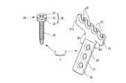
図1は本発明に係る固定具の要部構成を示す斜視図である。
図1に示したように、固定具1は骨折片を支持するプレート部材2、及び該プレート部材2を骨折片に取り付けるための取付用条材3を備えている。
前述したプレート部材2は、金属製板材を平面視が略T字形に成形してなり、骨折片に取り付けられる第1支持部21と骨折した骨本体に取り付けられる第2支持部22とが設けられている。(First embodiment of the present invention)
FIG. 1 is a perspective view showing a main configuration of a fixture according to the present invention.
As shown in FIG. 1, the fixture 1 includes a
The
帯状の第2支持部22の長手方向と平行をなす略中心軸上には、複数(図1にあっては3つ)の挿通孔24,24,…が互いに距離を隔てて、第2支持部22を貫通する様態で開設してあり、各挿通孔24,24,…には、頭部に脚部を垂下してなる螺子・釘等の他の取付用条材5(図3参照)をそれぞれ挿通させるようになっている。 A plurality of (three in FIG. 1) insertion holes 24, 24,... Are spaced apart from each other on a substantially central axis parallel to the longitudinal direction of the belt-like
また、前述した第1支持部21は平面視が略長方形の第1支持部本体21aを、その一長辺部の略中央位置から前記第2支持部22が連通するように設けてなり、側面視における第1支持部本体21aと第2支持部22とのなす第1角R1の角度、及び平面視における第1支持部本体21aと第2支持部22とのなす第2角R2は、それぞれ適宜の角度にしてある。 Further, the
この第1支持部本体21aの他長辺部側には、平面視が略U字形になるように切り欠いた複数(図1にあっては4つ)の切欠部23,23,…が、第1支持部本体21aの長辺方向へ適宜の間隔で設けてあり、各切欠部23,23,…は切欠部23の幅方向の中央位置上を通る中心軸がそれぞれ、前述した第2支持部22の中心軸と平行をなしている。また、第1支持部本体21aの切欠部23,23,…に臨む部分はテーパになしてある。 On the other long side portion side of the first support portion
一方、本発明に係る取付用条材3は、棒状の脚部35の一端に頭部30を設けてなり、頭部30は前述したプレート部材2の第1支持部21を挟持する挟持部34を備えている。前述した脚部35は棒体の周面に螺子山を形成してなり、後述する如く脚部35を骨折片に螺入させて骨折片をプレート部材2に圧接させ得るようになっている。 On the other hand, the mounting
また、挟持部34は、前記第1支持部本体21aを挟持し得るように調整した長さ寸法のロッド部33の両端に平板状の第1挟持部31及び第2挟持部32を、第1挟持部31及び第2挟持部32が互いに平行になるように設けてなり、挟持部34の第2挟持部32から前記脚部35が、ロッド部33の中心軸上に脚部35の中心軸が位置するように垂下させてある。
ロッド部33の直径は、前述した切欠部23の幅寸法より僅かに小さくしてあり、これによって取付用条材3を切欠部23の底部までスムーズに嵌入させることができるようになっている。In addition, the sandwiching
The diameter of the
なお、本実施の形態では、第1挟持部31及び第2挟持部32が互いに平行になるように設けてあるが、本発明はこれに限らず、プレート部材2の形状に応じて、該プレート部材2を挟持し得るように第1挟持部31及び第2挟持部32の形状及びその配置を定めればよい。また、第1支持部本体21aの切欠部23,23,…に臨む部分はテーパになしてあり、第1挟持部31の第2挟持部32に対向する部分に前記テーパに対応するテーパになしてあるが、本発明はこれに限らず、第1支持部本体21a及び第1挟持部31の対応する両部分を平坦になしてもよい。 In the present embodiment, the
次に、本発明に係る固定具1を用いて骨折片を固定する方法に付いて説明する。
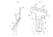
図2及び図3は、図1に示した固定具1を用いて骨折片を固定する手順を説明する説明図である。なお、図中、図1に示した部分に対応する部分には同じ番号を付してその説明を省略する。
プレート部材2の形状に応じて予め作成した位置決め冶具を用いて、取付用条材3,3,…を骨折片Bpに取り付ける位置を決定する。Next, a method for fixing a fractured piece using the fixing tool 1 according to the present invention will be described.
2 and 3 are explanatory views for explaining a procedure for fixing a fractured piece using the fixing tool 1 shown in FIG. In the figure, parts corresponding to those shown in FIG.
The position for attaching the attachment strips 3, 3,... To the fracture piece Bp is determined using a positioning jig prepared in advance according to the shape of the
図2(a)に示したように、決定した位置に、本発明に係る取付用条材3,3,…の脚部35(35,…)を骨折片Bpに、各取付用条材3,3,…の第2挟持部32(32,…)が骨折片Bpに当接するまで螺入させた後、各取付用条材3,3,…のロッド部33(33,…)をプレート部材2の切欠部23,23,…内に、ロッド部33(33,…)が切欠部23,23,…の底部に当接するまで進入させることによって、各取付用条材3,3,…の挟持部34(34,…)にプレート部材2を挟持・固定させる。 As shown in FIG. 2 (a), the legs 35 (35,...) Of the mounting
図2(b)に示したように、この状態で骨折片Bpを整復させ、所要の整復姿勢Sに対して、側面視における第1支持部本体21aと第2支持部22とのなす第1角R1の修正角度の見当を付ける。
そして、骨折片Bpを元の状態に戻してプレート部材2を各取付用条材3,3,…の挟持部34(34,…)から抜き出し、抜き出したプレート部材2の第1角R1の角度が修正角度になるようにプレート部材2をベンダー装置によって屈曲させる。As shown in FIG. 2B, the fracture piece Bp is reduced in this state, and the
Then, the fracture piece Bp is returned to the original state, and the
次に、図3(c)に示したように、第1角R1を所要の修正角度に屈曲させたプレート部材2を前同様にして各取付用条材3,3,…の挟持部34(34,…)に挟持・固定させ、骨折片Bpを所要の整復姿勢Sに整復させる。
このように、各取付用条材3,3,…を骨折片Bpに取り付けた状態でプレート部材2を着脱し得るため、骨折片Bpに対する取付用条材3,3,…の取り付け強度が低下することなく、プレート部材2の屈曲角度調整を容易に実施することができる。Next, as shown in FIG. 3 (c), the
In this way, since the
そして、図3(d)に示したように、プレート部材2の挿通孔24,24,…に螺子・釘といった他の取付用条材5,5,…を挿通させ、各他の取付用条材5,5,…を骨折した骨本体Bm内へ進入させることによってプレート部材2を骨本体Bmに固着させ、該プレート部材2によって骨折片Bpを所要の整復姿勢Sに固定する。 Then, as shown in FIG. 3 (d), other attachment strips 5,5,... Such as screws and nails are inserted through the insertion holes 24, 24,. The
このとき、プレート部材2は各取付用条材3,3,…の挟持部34(34,…)に挟持・固定されているため、プレート部材2と取付用条材3との間のガタの発生が可及的に低減されると共に、取付用条材3が姿勢が一定に強制され、骨折片Bpが所要の整復姿勢Sからずれることが防止される。 At this time, since the
ところで、本発明に係る固定具1にあっては、骨折片Bpに対する取付用条材3,3,…の取り付け強度が低下することなく、プレート部材2を着脱することが可能であるため、後述するように複数種類のプレート部材を予め備える固定具セットとすることによって、ベンダー装置による屈曲角度の調整作業を排除することができる。 By the way, in the fixture 1 according to the present invention, the
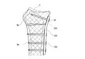
図4は、本発明に係る固定具セットに具備されたプレート部材を説明する説明図であり、図4(a)は側面視における第1支持部本体21aと第2支持部22とのなす第1角R1の角度を異ならせた場合を、図4(b)は平面視における第1支持部本体21aと第2支持部22とのなす第2角R2の角度を異ならせた場合をそれぞれ示している。 FIG. 4 is an explanatory view for explaining a plate member provided in the fixture set according to the present invention, and FIG. 4 (a) is a first view formed by the
同一部分の骨であってもその形状には個体差が存在するため、図4(a)(b)に示したように、側面視における第1支持部本体21aと第2支持部22とのなす第1角R1の角度を相異ならせた複数のプレート部材2,2,…、及び/又は、平面視における第1支持部本体21aと第2支持部22とのなす第2角R2の角度を異ならせた複数のプレート部材2,2,…を予め用意しておく。 Even if the bones are the same part, there are individual differences in their shapes. Therefore, as shown in FIGS. 4 (a) and 4 (b), the first
そして、前述した図3(c)に示したように、整復すべき骨の形状に応じた第1角R1の角度及び/又は第2角R2の角度を有するプレート部材2に交換するのである。
このように複数種類のプレート部材2,2,…を備える固定具セットによれば、ベンダー装置によるプレート部材2の屈曲角度の調整作業を排除することができ、骨折片Bpの固定作業を迅速に行うことができる。Then, as shown in FIG. 3C, the
As described above, according to the fixture set including a plurality of types of
なお、本実施の形態では、棒体の周面に螺子山が棒体の長手方向の略全長に亘って形成した脚部35を用いているが、本発明はこれに限らず、棒体の長手方向の一部、例えば先端部分に螺子山を設けた脚部35を用いてもよい。
また、図1に示した場合にあっては、取付用条材3の第1挟持部31及び第2挟持部32は円板状にしてあるが、本発明はこれに限らず、多角形状であってもよいことはいうまでもない。In addition, in this Embodiment, although the thread part formed the thread part over the substantially whole length of the longitudinal direction of the rod body is used for the peripheral surface of the rod body, this invention is not restricted to this, You may use the
Moreover, in the case shown in FIG. 1, although the
(本発明の第2の実施形態)
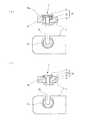
図5及び図6は本発明の第2の実施形態に係る固定具の部分拡大図であり、取付用条材3に設けた挟持部34からのプレート部材2の抜けを防止し得るようになしてある。図5に示した場合にあっては取付用条材3をプレート部材2に螺着させるようにした場合を、図6に示した場合にあっては、抜け防止手段としての突起を設けた場合をそれぞれ示している。なお、各図中、図1に示した部分に対応する部分には同じ番号を付してその説明を省略する。(Second embodiment of the present invention)
5 and 6 are partial enlarged views of the fixture according to the second embodiment of the present invention so that the
図5(a)に示したように、取付用条材3のロッド部33の周面であって、第1挟持部31に連通する部分に抜け防止手段としての雄螺子33aが設けてあり、プレート部材2の切欠部23の底部に臨む領域であって、プレート部材2を挟持した挟持部34の前記雄螺子33aに対向する部分に、雄螺子33aと螺合する抜け防止手段としての雌螺子25が設けてある。
また、図5(b)に示した場合にあっては、取付用条材3の第1挟持部31の周面に雄螺子31aが設けてある。As shown in FIG. 5 (a), a
Further, in the case shown in FIG. 5B, a
これら雄螺子33a,31aは例えば1/2ピッチ分だけ設けてあり、これによってプレート部材2を挟持部34に挟持させた後、取付用条材3を1/2回転だけ締め付けることによって雄螺子33a,31aと雌螺子25,25とを螺合固着させ、挟持部34,34からのプレート部材2,2の抜けを防止することができる。 These
一方、図6(a)に示した場合にあっては、プレート部材2の切欠部23に臨む部分に、取付用条材3のロッド部33を案内する案内面23a,23aが対向配置されており、両案内面23a,23aの切欠部23底部から適宜距離を隔てた位置に突起部23b,23bを設けて、両案内面23a,23a間の幅寸法を他の部分の幅寸法より狭くなした狭幅領域23cが形成されている。 On the other hand, in the case shown in FIG. 6 (a), guide surfaces 23a and 23a for guiding the
取付用条材3のロッド部33の外周面には互いに平行なフランジ部を設けて相対的に直径が小さい小径部33bが形成されており、該小径部33b以外の部分は相対的に直径が大きい大径部33cになしてある。このロッド部33の小径部33bの径寸法は前述した切欠部23の狭幅領域23c間の寸法より少し小さく、ロッド部33の大径部33cの径寸法は狭幅領域23c間の寸法より大きく切欠部23の幅寸法より少し小さい。 A flange portion parallel to each other is provided on the outer peripheral surface of the
このような固定具にあっては、取付用条材3の小径部33bを構成する両フランジ部とプレート部材2の案内面23a,23aとを平行になした状態でプレート部材2の切欠部23を取付用条材3の挟持部34内に、取付用条材3のロッド部33が突起部23b,23bを超えて切欠部23の底部に達するまで嵌合させた後、取付用条材3を半回転させる。これによって、ロッド部33の大径部33cが突起部23b,23bに当接して後退が阻止されるため、挟持部34からのプレート部材2の抜けを防止することができる。 In such a fixture, the
なお、前述した突起部23b,23bを、例えばプレート部材2内へ退入・プレート部材2内から進出させることができる構成になすことによって、小径部33bを具備しない取付用条材3を用いた場合であっても、前同様、挟持部34からのプレート部材2の抜けを防止することができる。 It should be noted that the above-described
また、図6(b)に示した場合にあっては、取付用条材3のロッド部33をプレート部材2の切欠部23内に、ロッド部33が切欠部23の底部に達するまで嵌入させたときに、互いに嵌合するように、取付用条材3の第1挟持部31の裏面及びプレート部材2の第1挟持部31に対向する部分に、凸部31c(又は凹部31d)及び凹部26(又は凸部27)が設けられている。
これによって、凸部31c(又は凹部31d)と凹部26(又は凸部27)とが嵌合するため、前同様、挟持部34,34からのプレート部材2,2の抜けを防止することができる。
なお、前述した凸部31c(又は凹部31d)及び凹部26(又は凸部27)は、第2挟持部32及びプレート部材2の第2挟持部32に対向する部分に設けてもよい。6B, the
As a result, the
In addition, you may provide the
(本発明の第3の実施形態)
図7及び図8は、本発明の第3の実施形態に係る固定具の一部破断部分拡大斜視図であり、プレート部材2によって取付用条材3の一部を挟持するようになしてある。なお、図中、図1に示した部分に対応する部分には同じ番号を付してその説明を省略する。(Third embodiment of the present invention)
7 and 8 are partially broken partial enlarged perspective views of the fixture according to the third embodiment of the present invention, in which a part of the mounting
図7に示したように、取付用条材3は頭部30の裏面中央に周面に螺子山が形成された脚部35を垂下してある。頭部30は、螺子頭本体の周縁にフランジ状の部分を設けて側面視が略凸形になしてあり、前記フランジ状の部分は抜け防止手段としての雄螺子部30bにしてある。 As shown in FIG. 7, the mounting
一方、プレート部材2の切欠部23に臨む内側部23d,23d及び内底部23eには、前記取付用条材3の頭部30の形状に対応した形状にしてあり、頭部30を案内するとともに該頭部30の周縁部を挟持する挟持溝23fがそれらの全域に亘って略U字状に形成してある。また、挟持溝23fの内底部23e部分及びその周囲部分には、前記頭部30の雄螺子部30bを螺合させる抜け防止手段としての雌螺子部23gが形成してある。 On the other hand, the
そして、取付用条材3,3,3を骨折片に、各頭部30,30,30が骨折片から所定寸法だけ突出するように取り付けた後、プレート部材2を取付用条材3,3,3に近付け、各切欠部23,23,23の挟持溝23f,23f,23f内に頭部30,30,30の周縁部たる雄螺子部30b,30b,30bを嵌入させ、該挟持溝23f,23f,23f内を内底部23e,23e,23eに当接するまで、頭部30,30,30の雄螺子部30b,30b,30bを摺動させることによって、プレート部材2と取付用条材3,3,3とを嵌着させた後、取付用条材3,3,3を締め付けることによって頭部30,30,30の雄螺子部30b,30b,30bを雌螺子部23g,23g,23gに螺合させ、取付用条材3,3,3とプレート部材2とを固着させる。 Then, after attaching the mounting
これによって、取付用条材3,3,3を螺入させた骨折片をプレート部材2に強く固着させることができるのに加え、各取付用条材3,3,3の頭部30,30,30がプレート部材2の挟持溝23f,23f,23fに挟持・固定されているため、取付用条材3,3,3の姿勢が一定に強制されと共に取付用条材3,3,3とプレート部材2との間のガタの発生が可及的に低減され、骨折片が所要の整復姿勢からずれることが防止される。更に、取付用条材3,3,3とプレート部材2とが固着してあるため、プレート部材2の切欠部23,23,23からの取付用条材3,3,3の抜けが防止される。 As a result, the fracture piece into which the mounting strips 3, 3, and 3 are screwed can be firmly fixed to the
一方、図8に示した場合では、図7に示した雌螺子部23g及び雄螺子部30bに代えて、頭部30の裏面周縁部に抜け防止手段としての凸部30cを設け、挟持溝23fの内底部23eから所定距離を隔てた位置に前記凸部30cが嵌合する抜け防止手段としての凹部23iが設けてある。そして、挟持溝23f内に頭部30の周縁部を嵌入させ、該挟持溝23f内を内底部23eに当接するまで、頭部30を摺動させることによって、プレート部材2と取付用条材3とを嵌着させた後、取付用条材3を回動させることによって頭部30の凸部30cを挟持溝23fの凹部23iに嵌合させ、取付用条材3とプレート部材2とを固着させている。 On the other hand, in the case shown in FIG. 8, instead of the
なお、図8に示した固定具にあっては、頭部30に凸部30cを形成し、挟持溝23fに凹部23iを形成した場合について示してあるが、本発明はこれに限らず、頭部30に凹部を形成し、挟持溝23fに前記凹部に嵌合する凸部を設けてもよいことはいうまでもない。 In the fixture shown in FIG. 8, the
ところで、このような構成の固定具では、プレート部材2と取付用条材3とを嵌着させた後に取付用条材3を更に締め付けることによって、取付用条材3、プレート部材2及び骨折片を互いに固着させることができるので、取付用条材3がプレート部材2から抜出することが抑制される。従って、図7に示した雌螺子部23g、雄螺子部30b、及び図8に示した凸部30c及び凹部23iを設けることなく、取付用条材3の頭部30の周縁部をプレート部材2の挟持溝23fに挟持・固定するようになした構成のものも、本発明の固定具とすることができる。 By the way, in the fixture of such a structure, after the
なお、本実施の形態で説明したプレート部材2についても、図4で示したように、側面視における第1支持部本体21aと第2支持部22とのなす第1角R1の角度を相異ならせた複数のプレート部材2,2,…、及び/又は、平面視における第1支持部本体21aと第2支持部22とのなす第2角R2の角度を異ならせた複数のプレート部材2,2,…を予め用意しておくことによって固定具セットとすることができることはいうまでもない。 In the
(その他の実施形態)
図9は、本発明のその他の実施形態に係る固定具の平面図であり、プレート部材2の第1支持部21と同様に、第2支持部22にも切欠部28,28,28が設けてある。なお、図中、図1に示した部分に対応する部分には同じ番号を付してその説明を省略する。(Other embodiments)
FIG. 9 is a plan view of a fixture according to another embodiment of the present invention. Like the
図9に示したように、プレート部材2の第1支持部21及び第2支持部22には、それぞれ複数の切欠部23,23,…、28,28,…が、例えば第1支持部21の一端側に設けた切欠部23を除いて略円弧形に設けてあり、各切欠部23,23,…、28,28,…は第1支持部21の一端側に設けた切欠部23の底部中央を中心とする同心円上に配置されている。 As shown in FIG. 9, each of the
このような固定具では、骨折片及び骨本体の各所定位置に図1に示した取付用条材3,3,…をそれぞれ螺入させておき、第1支持部21の一端側に設けた切欠部23を対応する取付用条材3の挟持部34に嵌合させて第1支持部21の当該切欠部23に臨む部分を挟持部34に挟持させた後、プレート部材2を前記取付用条材3を中心に回動させ、第1支持部21の他の切欠部23,23,…及び第2支持部22の切欠部28,28,…をそれぞれ対応する取付用条材3,3,…に嵌合させてプレート部材2を各挟持部34,34,…に挟持させる。
これによって、プレート部材2を骨折片及び骨本体に固着させた後であっても、ワンタッチで当該プレート部材2を脱着させることができる。In such a fixture, the mounting
Accordingly, even after the
1 固定具
2 プレート部材
3 取付用条材
21 第1支持部
21a 第1支持部本体
22 第2支持部
23 切欠部
23c 狭幅領域
23d 挟持溝
24 挿通孔
26 凹部
27 凸部
30 頭部
31 第1挟持部
31c 凸部
31d 凹部
32 第2挟持部
33 ロッド部
33b 小径部
33c 大径部
34 挟持部
35 脚部
R1 第1角
R2 第2角DESCRIPTION OF SYMBOLS 1
Claims (10)
Translated fromJapanese少なくとも前記プレート部材の骨折片に取り付けられる領域縁部の適宜位置には、前記取付用条材の頭部を嵌入させる複数の切欠部が設けてあり、
少なくともプレート部材を骨折片に取り付ける取付用条材の頭部には、前記プレート部材を挟持する挟持部が設けてある
ことを特徴とする固定具。A plate member attached from the fractured bone main body to the fracture piece, and a plurality of attachment strips for attaching the plate member to the bone main body or the fracture piece, each having a leg portion suspended from the head. In a fixture for fixing a fracture piece to a required posture by a plate member attached to the bone body and the fracture piece with a mounting strip,
At least an appropriate position of a region edge portion attached to the fracture piece of the plate member is provided with a plurality of notches for inserting the heads of the attachment strips,
A fixing tool, wherein at least a head portion of a mounting strip for attaching a plate member to a fracture piece is provided with a clamping portion for clamping the plate member.
前記挟持部は、対向配置した第1挟持部及び第2挟持部を前記切欠部内へ嵌入させるロッド部で連結してなり、該ロッド部には、前記狭幅部の寸法より小さい径寸法の部分と、前記狭幅部の寸法より大きい径寸法の部分とがロッド部の周方向へ位置を異ならせて設けてある請求項2記載の固定具。A portion facing the notch portion of the plate member, a portion at a predetermined distance from the bottom portion of the notch portion, a narrow width portion having a width smaller than the width of other portions of the notch Is provided,
The sandwiching portion is formed by connecting the first sandwiching portion and the second sandwiching portion arranged opposite to each other by a rod portion that fits into the notch portion, and the rod portion has a diameter smaller than that of the narrow width portion. The fixing tool according to claim 2, wherein a portion having a diameter larger than that of the narrow width portion is provided in a different position in the circumferential direction of the rod portion.
少なくとも前記プレート部材の骨折片に取り付けられる領域縁部の適宜位置には、前記取付用条材の頭部を嵌入させる複数の切欠部が設けてあり、プレート部材の切欠部に対向する部分には、前記取付用条材の頭部の縁部を挟持する挟持溝が設けてあることを特徴とする固定具。A plate member attached from the fractured bone main body to the fracture piece, and a plurality of attachment strips for attaching the plate member to the bone main body or the fracture piece, each having a leg portion suspended from the head. In a fixture for fixing a fracture piece to a required posture by a plate member attached to the bone body and the fracture piece with a mounting strip,
A plurality of notches for inserting the heads of the mounting strips are provided at appropriate positions of the region edges attached to the fracture pieces of the plate member, and the portions facing the notches of the plate member A fixing tool characterized in that a clamping groove is provided for clamping the edge of the head of the mounting strip.
請求項1から9のいずれかに記載したプレート部材及び取付用条材を備え、
各プレート部材は、骨折片に取り付けられる第1部分と骨本体に取り付けられる第2部分とを具備し、
側面視において前記第1部分と第2部分とがなす第1角の角度、及び/又は平面視において前記第1部分と第2部分とがなす第2角の角度は、各プレート部材で相異ならせてある
ことを特徴とする固定具セット。A plurality of plate members attached from the fractured bone main body to the fracture piece, and a plurality of mounting strips for mounting the plate member to the bone main body or the fracture piece. A fixture set for attaching a plate member selected from each plate member to a bone body and a fracture piece with each attachment strip, and fixing the fracture piece to a required posture by the plate member,
A plate member according to any one of claims 1 to 9 and a mounting strip.
Each plate member comprises a first part attached to the fracture piece and a second part attached to the bone body;
The angle of the first angle formed by the first portion and the second portion in the side view and / or the angle of the second angle formed by the first portion and the second portion in the plan view are different for each plate member. A set of fasteners characterized in that
Priority Applications (1)
| Application Number | Priority Date | Filing Date | Title |
|---|---|---|---|
| JP2007047155AJP4572301B2 (en) | 2007-02-27 | 2007-02-27 | Fixture and fixture set |
Applications Claiming Priority (1)
| Application Number | Priority Date | Filing Date | Title |
|---|---|---|---|
| JP2007047155AJP4572301B2 (en) | 2007-02-27 | 2007-02-27 | Fixture and fixture set |
Publications (2)
| Publication Number | Publication Date |
|---|---|
| JP2008206789Atrue JP2008206789A (en) | 2008-09-11 |
| JP4572301B2 JP4572301B2 (en) | 2010-11-04 |
Family
ID=39783607
Family Applications (1)
| Application Number | Title | Priority Date | Filing Date |
|---|---|---|---|
| JP2007047155AActiveJP4572301B2 (en) | 2007-02-27 | 2007-02-27 | Fixture and fixture set |
Country Status (1)
| Country | Link |
|---|---|
| JP (1) | JP4572301B2 (en) |
Cited By (6)
| Publication number | Priority date | Publication date | Assignee | Title |
|---|---|---|---|---|
| US20120203228A1 (en)* | 2010-05-07 | 2012-08-09 | Osteomed L.P. | System for Treating Bone Fractures |
| JP2012523279A (en)* | 2009-04-08 | 2012-10-04 | シンセス ゲゼルシャフト ミット ベシュレンクテル ハフツング | Bone joint plate with keyhole features |
| JP2012524634A (en)* | 2009-04-24 | 2012-10-18 | シンセス ゲゼルシャフト ミット ベシュレンクテル ハフツング | Multiple screw |
| JP2014512865A (en)* | 2011-02-14 | 2014-05-29 | スケルタル ダイナミクス エルエルシー | Fracture fixation plate |
| EP2884922A4 (en)* | 2012-08-20 | 2016-04-13 | Ebi Llc | Implant with semi-enclosed screws |
| US9833270B2 (en) | 2013-09-19 | 2017-12-05 | Mcginley Engineered Solutions, Llc | Variable angle blade plate system and method |
Citations (2)
| Publication number | Priority date | Publication date | Assignee | Title |
|---|---|---|---|---|
| JP2003503145A (en)* | 1999-07-01 | 2003-01-28 | スピネヴィジョン エス.エー. | Spine osteosynthesis plate and osteosynthesis system |
| WO2005034780A1 (en)* | 2003-09-17 | 2005-04-21 | Hand Innovations, Llc | Anatomical distal radius fracture fixation plate and methods of using the same |
- 2007
- 2007-02-27JPJP2007047155Apatent/JP4572301B2/enactiveActive
Patent Citations (2)
| Publication number | Priority date | Publication date | Assignee | Title |
|---|---|---|---|---|
| JP2003503145A (en)* | 1999-07-01 | 2003-01-28 | スピネヴィジョン エス.エー. | Spine osteosynthesis plate and osteosynthesis system |
| WO2005034780A1 (en)* | 2003-09-17 | 2005-04-21 | Hand Innovations, Llc | Anatomical distal radius fracture fixation plate and methods of using the same |
Cited By (15)
| Publication number | Priority date | Publication date | Assignee | Title |
|---|---|---|---|---|
| JP2012523279A (en)* | 2009-04-08 | 2012-10-04 | シンセス ゲゼルシャフト ミット ベシュレンクテル ハフツング | Bone joint plate with keyhole features |
| US10335214B2 (en) | 2009-04-24 | 2019-07-02 | DePuy Synthes Products, Inc. | Multiplexed screws |
| JP2012524634A (en)* | 2009-04-24 | 2012-10-18 | シンセス ゲゼルシャフト ミット ベシュレンクテル ハフツング | Multiple screw |
| US9066766B2 (en) | 2010-05-07 | 2015-06-30 | Osteomed Llc | System for treating bone fractures |
| US20140094804A1 (en)* | 2010-05-07 | 2014-04-03 | Raymond B. Raven, III | System for treating bone fractures |
| US20120203228A1 (en)* | 2010-05-07 | 2012-08-09 | Osteomed L.P. | System for Treating Bone Fractures |
| US9295506B2 (en) | 2010-05-07 | 2016-03-29 | Osteomed Llc | System for treating bone fractures |
| US9649141B2 (en)* | 2010-05-07 | 2017-05-16 | Mcginley Engineered Solutions, Llc | System for treating bone fractures |
| US10111688B2 (en) | 2010-05-07 | 2018-10-30 | Mcginley Engineered Solutions, Llc | System for treating bone fractures |
| US8603148B2 (en)* | 2010-05-07 | 2013-12-10 | Raymond B. Raven, III | System for treating bone fractures |
| JP2014512865A (en)* | 2011-02-14 | 2014-05-29 | スケルタル ダイナミクス エルエルシー | Fracture fixation plate |
| EP2884922A4 (en)* | 2012-08-20 | 2016-04-13 | Ebi Llc | Implant with semi-enclosed screws |
| US9387021B2 (en) | 2012-08-20 | 2016-07-12 | Ebi, Llc | Implant with semi-enclosed screws |
| US9833270B2 (en) | 2013-09-19 | 2017-12-05 | Mcginley Engineered Solutions, Llc | Variable angle blade plate system and method |
| US10117689B2 (en) | 2013-09-19 | 2018-11-06 | Mcginley Engineered Solutions, Llc | Variable angle blade plate system and method |
Also Published As
| Publication number | Publication date |
|---|---|
| JP4572301B2 (en) | 2010-11-04 |
Similar Documents
| Publication | Publication Date | Title |
|---|---|---|
| US20230084400A1 (en) | Orthopedic Implant In The Form Of A Plate To Be Fixed Between Two Bone Parts | |
| JP5519676B2 (en) | Orthodontic device worn outside the bone | |
| JP4572301B2 (en) | Fixture and fixture set | |
| JP4619048B2 (en) | Osteosynthesis plate or similar implant and spherical socket | |
| JP3742648B2 (en) | Adjustable clamp for bone anchoring element | |
| JP5847412B2 (en) | Bone fixation device | |
| JP5912056B2 (en) | Multi-axis pedicle screw and fixation system kit including the same | |
| KR101197729B1 (en) | Anchoring Device for Anchoring a Rod in Bones or Vertebrae | |
| US6958065B2 (en) | Rod for cervical vertebra and connecting system thereof | |
| JP2008543381A (en) | Bone screw fixation mechanism and method of use | |
| US12232775B2 (en) | Anchoring assembly for anchoring a rod to a bone or a vertebra | |
| JPH0739808U (en) | Fixator for posterior spinal correction | |
| JP2010155076A (en) | Receiving part for receiving rod for coupling the rod to bone anchoring element and bone anchoring device having the receiving part | |
| KR20080037609A (en) | Bone Lock and Locking Method with Locking Cap | |
| JPH07313524A (en) | Bone joining apparatus | |
| JP4478693B2 (en) | Medical device, biological implant, adapter device, and method for spatially adjusting an aiming device relative to a biological implant | |
| KR20150056067A (en) | Bone anchor and bone anchoring assembly comprising the same | |
| JP2013255794A (en) | Polyaxial bone anchoring device | |
| JP2017511192A (en) | Fixation device for fixing the surgical implant in place, and the process of attaching this fixation device to the anchor means | |
| US20190314072A1 (en) | Fixture for funnel chest correction bar and funnel chest correction device | |
| CA2882155A1 (en) | Pivoting spinal fixation devices | |
| US11160640B2 (en) | Orthodontic implant structure and orthodontic implant jig | |
| TW200533846A (en) | Position detecting switch fixture for cylinder | |
| JP6367077B2 (en) | Skull fixation device | |
| JP2003250822A (en) | Device for connecting rod |
Legal Events
| Date | Code | Title | Description |
|---|---|---|---|
| A621 | Written request for application examination | Free format text:JAPANESE INTERMEDIATE CODE: A621 Effective date:20091109 | |
| A977 | Report on retrieval | Free format text:JAPANESE INTERMEDIATE CODE: A971007 Effective date:20100422 | |
| A131 | Notification of reasons for refusal | Free format text:JAPANESE INTERMEDIATE CODE: A131 Effective date:20100427 | |
| A521 | Written amendment | Free format text:JAPANESE INTERMEDIATE CODE: A523 Effective date:20100628 | |
| TRDD | Decision of grant or rejection written | ||
| A01 | Written decision to grant a patent or to grant a registration (utility model) | Free format text:JAPANESE INTERMEDIATE CODE: A01 Effective date:20100720 | |
| A01 | Written decision to grant a patent or to grant a registration (utility model) | Free format text:JAPANESE INTERMEDIATE CODE: A01 | |
| R150 | Certificate of patent or registration of utility model | Free format text:JAPANESE INTERMEDIATE CODE: R150 |