JP2008205835A - Ip telephone communication equipment - Google Patents
Ip telephone communication equipmentDownload PDFInfo
- Publication number
- JP2008205835A JP2008205835AJP2007039781AJP2007039781AJP2008205835AJP 2008205835 AJP2008205835 AJP 2008205835AJP 2007039781 AJP2007039781 AJP 2007039781AJP 2007039781 AJP2007039781 AJP 2007039781AJP 2008205835 AJP2008205835 AJP 2008205835A
- Authority
- JP
- Japan
- Prior art keywords
- call control
- control server
- server
- call
- terminal
- Prior art date
- Legal status (The legal status is an assumption and is not a legal conclusion. Google has not performed a legal analysis and makes no representation as to the accuracy of the status listed.)
- Pending
Links
- 238000004891communicationMethods0.000titleclaimsabstractdescription34
- 230000011664signalingEffects0.000claimsabstractdescription6
- 230000004308accommodationEffects0.000claimsdescription5
- 239000000284extractSubstances0.000claimsdescription3
- 238000000034methodMethods0.000description6
- 230000005540biological transmissionEffects0.000description5
- 238000005516engineering processMethods0.000description3
- 238000010586diagramMethods0.000description2
- 230000001105regulatory effectEffects0.000description2
- 238000006243chemical reactionMethods0.000description1
- 239000012141concentrateSubstances0.000description1
- 238000010295mobile communicationMethods0.000description1
- 239000013307optical fiberSubstances0.000description1
- 238000011084recoveryMethods0.000description1
Images


Landscapes
- Data Exchanges In Wide-Area Networks (AREA)
- Telephonic Communication Services (AREA)
Abstract
Description
Translated fromJapanese本発明は、IP電話通信装置に関し、特に、災害型輻輳に耐性があるIP電話通信装置に関する。 The present invention relates to an IP telephone communication apparatus, and more particularly to an IP telephone communication apparatus that is resistant to disaster-type congestion.
電話網における災害型輻輳とは、地震や台風・洪水など突発的災害が発生した場合に、安否問い合わせなどの呼が被災地に集中し、通信網が正常なサービスを提供できなくなる状態をいう。従来、電話網においては、主に発信側で被災地に向けた呼を規制することで、かかる輻輳状態からの回復が図られている。 Disaster congestion in the telephone network refers to a state in which calls such as safety inquiries are concentrated in the affected area when a sudden disaster such as an earthquake, typhoon, or flood occurs, and the communication network cannot provide normal services. 2. Description of the Related Art Conventionally, in a telephone network, recovery from such a congested state has been achieved by restricting calls directed to a disaster area mainly on the calling side.
特許文献1には、輻輳時に通話時間を制限する通話規制方法が開示されている。特許文献2には、一律に規制を行うのではなく、例えば官公庁などの優先して着信すべき加入者への呼を確保する輻輳時の優先接続制御方法が開示されている。特許文献3には、被災状況及び交換機の位置、被災地のトラヒックを考慮した被災時緊急交換機制御装置が開示されている。特許文献4には、被災地にある移動体通信システムの端末に積極的に通信規制情報を提供することにより、端末からの通信の集中を抑制する方法が述べられている。これらはいずれも、何らかの手段で呼を規制することにより、輻輳を回避しようというものである。
また一方で、VoIP(Voice over IP)技術の発展に伴ってIP網上で電話サービスを提供する新たな形態の電話網(以下、IP電話網と称する)が広がっている。IP電話網では、一般的に、電話サービスの制御を行う呼制御サーバと端末とがIP網を介して接続されて呼制御信号のやり取りをし、一方、音声信号は呼制御信号とは別個に、発着信端末同士がIP網を介して直接伝送する。 On the other hand, with the development of VoIP (Voice over IP) technology, a new type of telephone network (hereinafter referred to as an IP telephone network) that provides telephone services over the IP network is spreading. In an IP telephone network, generally, a call control server that controls telephone services and a terminal are connected via the IP network to exchange call control signals, while voice signals are separated from call control signals. The transmitting and receiving terminals directly transmit via the IP network.
かかる構成においては、呼制御サーバ毎に予め定められた地域のすべての端末の呼制御を行うようになされていて、電話番号を用いて、経路選択、即ち、着信端末の制御を受け持つ呼制御サーバの決定が行われる。呼制御サーバは、配下の端末から着信先の0ABJ形式の電話番号(電話番号から相手端末の存在する地域がわかる)を含む呼設定要求を受けると、かかる着信先電話番号を分析し、着信先端末の存在する地域を判断する。これにより着信先端末を制御する呼制御サーバが特定でき、その呼制御サーバへ呼設定を要求することができる。 In such a configuration, call control is performed for all terminals in a predetermined area for each call control server, and the call control server is responsible for route selection, that is, control of the receiving terminal, using a telephone number. The decision is made. When the call control server receives a call setting request including a telephone number in the 0ABJ format of the destination (from the telephone number, the area where the other terminal exists) from the subordinate terminal, the call control server analyzes the destination telephone number, Determine the region where the terminal is located. As a result, the call control server that controls the destination terminal can be specified, and call setting can be requested from the call control server.
ところで、近年光ファイバーを利用した伝送路が発達し、IP網にはGbpsオーダの伝送設備が設置されている。IP電話で使用する帯域幅は片側高々10Kbps程度であり、IP電話の通話パケット及び端末‐呼制御サーバ間の信号パケットの数や長さを考慮してもIP網の伝送路にはかなりの余裕がある。よって、災害型輻輳においてもIP網自体には十分の疎通能力があると考えられる。 By the way, in recent years, transmission lines using optical fibers have been developed, and transmission facilities of the order of Gbps are installed in the IP network. The bandwidth used for IP telephone is about 10 Kbps at one side at most. Considering the number and length of IP telephone call packets and terminal-call control server, there is a considerable margin in the IP network transmission path. There is. Therefore, it is considered that the IP network itself has sufficient communication capability even in disaster-type congestion.
このように、IP電話網で、災害型輻輳時において輻輳するのは、言い換えると、資源及び/または処理能力が不足するのは、被災地に存在する通信端末を配下に持つ呼制御サーバである。このため、被災地以外の地域にある呼制御サーバの資源及び/または処理能力に余裕があったとしても、被災地の呼制御サーバが輻輳していれば通信の確保ができなくなる。 As described above, in the IP telephone network, congestion occurs at the time of disaster-type congestion. In other words, it is a call control server having a communication terminal subordinate to a disaster area that lacks resources and / or processing capability. . For this reason, even if there is a margin in the resources and / or processing capacity of the call control server in an area other than the disaster area, communication cannot be secured if the call control server in the disaster area is congested.
上記した従来の災害型輻輳に対する規制方法及び/または装置では、呼の規制をその目的としているために、IP電話網において伝送路に余裕があることを活かすことができない。従って、災害型輻輳において大きな影響を受ける呼制御サーバの負荷を、他の地域の呼制御サーバに分散すれば、伝送路の制限及び/または呼制御サーバ全体としての処理能力の制限に達するまで、通信の確保が可能になる。 The above-described conventional regulation method and / or apparatus for disaster-type congestion is intended to regulate calls, so that it is not possible to make use of the fact that there is room in the IP telephone network. Therefore, if the load of the call control server that is greatly affected by the disaster type congestion is distributed to the call control servers in other regions, until the limit of the transmission path and / or the processing capacity of the call control server as a whole is reached, Communication can be secured.
本発明の目的は、災害型輻輳発生に起きる特定の呼制御サーバへのトラヒック集中が起きにくい、呼制御サーバの負荷が全体に分散された、IP電話通信システムを提供することである。 An object of the present invention is to provide an IP telephone communication system in which traffic concentration on a specific call control server that occurs due to occurrence of disaster-type congestion hardly occurs and the load of the call control server is distributed throughout.
本発明によるIP電話通信装置は、自身の収容端末のシグナリング処理を行う複数の呼制御サーバを含むIP電話通信装置であって、該呼制御サーバのうちの少なくとも1つとその収容端末との間の相互通信に必要な識別情報データを保持する呼制御サーバ判別サーバを含み、該呼制御サーバは、該端末の1から呼設定要求を受信すると、該呼設定要求から着信先電話番号を抽出して該呼制御判別サーバへ送信し、該呼制御判別サーバは、受信した該着信先電話番号から該識別情報データを検索して、該呼制御サーバへ返信することを特徴とすることを特徴とする。 An IP telephone communication apparatus according to the present invention is an IP telephone communication apparatus including a plurality of call control servers that perform signaling processing of its own accommodation terminal, and is between the at least one of the call control servers and the accommodation terminal. A call control server discriminating server that holds identification information data necessary for mutual communication; when the call control server receives a call setting request from one of the terminals, it extracts a destination telephone number from the call setting request The call control determination server transmits to the call control determination server, the call control determination server retrieves the identification information data from the received destination telephone number, and returns the identification information data to the call control server. .
本発明によるIP電話通信システムによれば、呼制御サーバの負荷は全体に分散されて特定の呼制御サーバだけが輻輳する状態は起きにくくなる。今日のIP電話網の伝送路は十分な余裕があると考えられることから、呼制御サーバの負荷分散で呼制御サーバの輻輳耐性が強化されてひいては災害型輻輳への耐性を上げる効果が得られる。 According to the IP telephone communication system according to the present invention, the load of the call control server is distributed to the whole, and it is difficult for only a specific call control server to be congested. Since it is considered that the transmission path of today's IP telephone network has a sufficient margin, the load resistance of the call control server enhances the congestion resistance of the call control server, which in turn increases the resistance to disaster-type congestion. .
また、本発明によるIP電話通信システムによれば、輻輳時以外においても、通信量の多いユーザの端末と少ないユーザの端末とを組み合わせて呼制御サーバに収容することにより、呼制御サーバの能力を有効に利用することができる。 Further, according to the IP telephone communication system according to the present invention, the capacity of the call control server can be increased by accommodating the user terminal with a large amount of communication and the terminal of a user with a small amount even in times other than the congestion. It can be used effectively.
本発明の実施例について添付の図面を参照しつつ詳細に説明する。 Embodiments of the present invention will be described in detail with reference to the accompanying drawings.
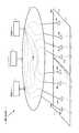
図1は、本発明の実施例であり、IP電話網の全体構成を示している。本発明によるIP電話通信装置100は、呼制御を行う複数の呼制御サーバ1及び2、enumサービスを提供する、呼制御サーバ判別手段である1以上のenumサーバ4を含み、それぞれIP網3を介して接続されている。また、地域10、20にはそれぞれ通信端末11〜14、21〜24が位置しており、これらはIP網3を介して通信可能である。本発明によるIP電話通信システム100には、いずれの装置及び端末も複数存在してもよいが、本実施例では、理解を容易にするために、発信側と着信側のみを示している。 FIG. 1 is an embodiment of the present invention, and shows the overall configuration of an IP telephone network. An IP telephone communication apparatus 100 according to the present invention includes a plurality of
呼制御サーバ1、2は、それぞれ配下に端末11〜14、21〜24を有する。図1に示すように、端末11〜14、21〜24は地域との関連を無くした形で呼制御サーバに収容される。例えば、図1において、地域10にある端末11と端末12とは呼制御サーバ1に収容されるが、同じ地域にある端末13及び端末14は呼制御サーバ2に収容されている。また、地域20の端末21及び端末22は呼制御サーバ1に収容されている。それぞれの呼制御サーバは、呼制御サーバ毎にその資源や処理能力などに応じて定められた収容数の上限を超えない限り、ランダムに端末を収容させていってもよい。例えば、地域毎の端末数の全体における割合を算出してその割合に応じて各地域の端末を抽出して収容させてもよい。このように、特定の地域のトラヒックが増大しても、特定の呼制御サーバだけにトラヒックが集中することがないように端末を収容させておく。 The
enumサーバ4は、電話番号とその電話番号を有する端末を制御する呼制御サーバとを対応付ける。enum技術とは、DNS(Domain Name System)をデータベースとする技術であって、enum DNSには、規定のフォーマットに従って電話番号に基づいて生成されたドメイン名が予め登録してある。該ドメイン名を入力すると、対応するアプリケーション(電話、電子メール、FAXなど)のURI(Uniform Resource Identifier)を出力する。 The
enumサーバ4は、電話番号と呼制御サーバのURIを対応づけたデータベースを内部に有していて、電話番号からその電話番号(端末)を制御する呼制御サーバのURIを得ることができる。発信側呼制御サーバが、呼設定要求を受信した際に行う、enumサーバ4への問い合わせのようすを図2に示す。ここで得た着信側呼制御サーバのURIを用いて、例えばenumサーバに存するDNSから、着信側呼制御サーバのIPアドレスを得ることができ、着信側呼制御サーバとシグナリングをやりとりすることが可能になる。 The
端末11〜14及び21〜24は、通話機能を有するIP電話用端末である。例えば、IP電話機、専用ソフトウェアをインストールしたパーソナルコンピュータ、携帯端末などであってもよい。 The terminals 11 to 14 and 21 to 24 are IP telephone terminals having a call function. For example, it may be an IP phone, a personal computer installed with dedicated software, a portable terminal, or the like.
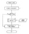
図3は、呼制御サーバ1が実行する処理手順の概要を示している。ここで、通信要求が呼制御サーバ1の配下にある、例えば端末11からあったものとする。また、端末11は呼制御サーバ2の配下にある端末23への着信を所望するものとする。 FIG. 3 shows an outline of a processing procedure executed by the
呼制御サーバ1は、配下の端末からの呼設定要求を監視している。端末11が、発呼を行うことにより、呼設定の要求が呼制御サーバ1にIP網3を介して送信され、呼制御サーバ1はこれを受信する(S1)。このとき、例えば、SIPなどの適当なプロトコルが用いられてシグナリング処理が行われてもよい。呼制御サーバ1は、受信した呼設定要求から着信先端末の電話番号を抽出し、該着信先端末を収容している呼制御サーバ2の位置を判断する(S2)。このとき、呼制御サーバ1は、電話番号だけでは着信先端末を制御する呼制御サーバが判別できない場合がある。呼制御サーバ1が、相手呼制御サーバを判別できるのは、着信先端末も自分が収容している場合などである。また、呼制御サーバ1は、enumサーバ4に問い合わせを行って得た呼制御サーバの識別情報を、例えば日数単位による所定期間、記憶させておいてもよい。これにより、enumサーバへの問い合わせを減らすことができる。 The
着信先端末を制御する着信側呼制御サーバを判別できた場合には、その呼制御サーバと協働して呼制御を行い、発着信端末間の通話を開始する準備を行う(S4)。 If the called side call control server that controls the destination terminal can be determined, call control is performed in cooperation with the call control server, and preparation for starting a call between the calling and called terminals is made (S4).
着信先端末を制御する呼制御サーバを判別できなかった場合には、着信先端末電話番号を用いてenumサーバ4へ問い合わせを行う(S3)。enumサーバ4は、例えば、図4に示すような電話番号と該電話番号を制御する呼制御サーバとの間の識別情報データについての変換テーブルを保持していて、着信先端末の電話番号からその端末の呼制御を行う呼制御サーバ2のURIを検出する。さらに、enumサーバ内のDNSにより、URIからIPアドレスを取得して、問い合わせ元の呼制御サーバ1に送信する。 If the call control server that controls the destination terminal cannot be determined, an inquiry is made to the
呼制御サーバ1は、相手呼制御サーバ2のIPアドレスを受信すると、IP網3を介して、呼制御サーバ2と呼制御のためのシグナリングを開始し、発着信端末間の通話の準備を行う(S4)。 When the
1 呼制御サーバ
2 呼制御サーバ
3 IP網
4 enumサーバ
10 地域
20 地域
11〜14 通信用端末
21〜24 通信用端末
100 IP電話通信装置DESCRIPTION OF
Claims (2)
Translated fromJapanese前記呼制御サーバのうちの少なくとも1つとその収容端末との間の相互通信に必要な識別情報データを保持する呼制御サーバ判別サーバを含み、
前記呼制御サーバは、前記端末の1から呼設定要求を受信すると、前記呼設定要求から着信先電話番号を抽出して前記呼制御判別サーバへ送信し、
前記呼制御判別サーバは、受信した前記着信先電話番号から前記識別情報データを検索して、前記呼制御サーバへ返信することを特徴とするIP電話通信装置。An IP telephone communication apparatus including a plurality of call control servers for performing signaling processing of its own accommodation terminal,
Including a call control server determination server that holds identification information data necessary for mutual communication between at least one of the call control servers and the accommodation terminal;
When the call control server receives a call setting request from one of the terminals, it extracts a destination telephone number from the call setting request and transmits it to the call control determination server;
The IP telephone communication apparatus, wherein the call control determination server searches for the identification information data from the received destination telephone number and sends it back to the call control server.
Priority Applications (1)
| Application Number | Priority Date | Filing Date | Title |
|---|---|---|---|
| JP2007039781AJP2008205835A (en) | 2007-02-20 | 2007-02-20 | Ip telephone communication equipment |
Applications Claiming Priority (1)
| Application Number | Priority Date | Filing Date | Title |
|---|---|---|---|
| JP2007039781AJP2008205835A (en) | 2007-02-20 | 2007-02-20 | Ip telephone communication equipment |
Publications (1)
| Publication Number | Publication Date |
|---|---|
| JP2008205835Atrue JP2008205835A (en) | 2008-09-04 |
Family
ID=39782845
Family Applications (1)
| Application Number | Title | Priority Date | Filing Date |
|---|---|---|---|
| JP2007039781APendingJP2008205835A (en) | 2007-02-20 | 2007-02-20 | Ip telephone communication equipment |
Country Status (1)
| Country | Link |
|---|---|
| JP (1) | JP2008205835A (en) |
Cited By (1)
| Publication number | Priority date | Publication date | Assignee | Title |
|---|---|---|---|---|
| JP2017034399A (en)* | 2015-07-30 | 2017-02-09 | 日本電信電話株式会社 | Enum system and load distribution method for enum system |
- 2007
- 2007-02-20JPJP2007039781Apatent/JP2008205835A/enactivePending
Cited By (1)
| Publication number | Priority date | Publication date | Assignee | Title |
|---|---|---|---|---|
| JP2017034399A (en)* | 2015-07-30 | 2017-02-09 | 日本電信電話株式会社 | Enum system and load distribution method for enum system |
Similar Documents
| Publication | Publication Date | Title |
|---|---|---|
| US12375896B2 (en) | Method and system for emergency call management | |
| EP2501119B1 (en) | A gateway for the survivability of an enterprise network using sip | |
| US9386053B2 (en) | Disaster recovery with a central conferencing routing server | |
| US8345556B2 (en) | Congestion control system, service edge node, guidance server, congestion control method, program therefor, and recording medium recorded therewith | |
| JP4576115B2 (en) | VoIP gateway device and method for controlling call arrival and departure in VoIP gateway device | |
| JP5202383B2 (en) | COMMUNICATION NETWORK SYSTEM, ITS CALL CONTROL DEVICE, AND TRANSMISSION CONTROL METHOD | |
| JP2007243557A (en) | Ip telephone system for accommodating wireless terminal | |
| JP2008205835A (en) | Ip telephone communication equipment | |
| JP4503526B2 (en) | Call control method and call control system | |
| JP4151021B2 (en) | IP telephone service system, incomplete call information notification system, incomplete call information notification method and program | |
| CN107666543B (en) | Data processing method and device | |
| JP5587249B2 (en) | Information management method, congestion control method, and congestion control apparatus | |
| JP4662956B2 (en) | Data transfer method and system | |
| JP2005094715A (en) | Voice gateway device | |
| JP2004040653A (en) | VoIP communication device and method for determining VoIP communication conditions | |
| JP2017175248A (en) | System and method for enum/dns query priority control | |
| JP5236509B2 (en) | Telephone terminal and outgoing call control method and system thereof | |
| JP2010109878A (en) | Main apparatus and bandwidth allocating method | |
| JP2005333411A (en) | Voip system, session setting control method therefor, and control unit used therefor | |
| JP2006019984A (en) | Telephone exchange device and network telephone system | |
| JP5105074B2 (en) | IP phone system | |
| JP2013201506A (en) | Ip telephone system, ip telephone terminal, ip telephone conversation method, and ip telephone conversation program |