JP2008203598A - Laser concentrator - Google Patents
Laser concentratorDownload PDFInfo
- Publication number
- JP2008203598A JP2008203598AJP2007040435AJP2007040435AJP2008203598AJP 2008203598 AJP2008203598 AJP 2008203598AJP 2007040435 AJP2007040435 AJP 2007040435AJP 2007040435 AJP2007040435 AJP 2007040435AJP 2008203598 AJP2008203598 AJP 2008203598A
- Authority
- JP
- Japan
- Prior art keywords
- laser
- optical fiber
- light emitting
- incident
- light
- Prior art date
- Legal status (The legal status is an assumption and is not a legal conclusion. Google has not performed a legal analysis and makes no representation as to the accuracy of the status listed.)
- Pending
Links
Images


Landscapes
- Optical Couplings Of Light Guides (AREA)
Abstract
Description
Translated fromJapanese本発明は、レーザーバーと光ファイバーを備えたレーザー集光装置に関する。 The present invention relates to a laser focusing device including a laser bar and an optical fiber.
レーザーダイオードアレイ(レーザーバー)から出射されたレーザー光が、ビームコリメーターレンズで一旦集光され、その集光されたレーザー光が、ビームコリメーターレンズと対向配置された複数の各導波路(光ファイバー)に入射されるようにしたレーザー集光装置が従来から知られている(例えば、特許文献1参照)。 The laser light emitted from the laser diode array (laser bar) is once condensed by the beam collimator lens, and the collected laser light is arranged in a plurality of waveguides (optical fibers) arranged to face the beam collimator lens. ) Is conventionally known (see, for example, Patent Document 1).
しかしながら、この特許文献1に記載のレーザー集光装置では、レーザーダイオードアレイ(レーザーバー)とビームコリメーターレンズと導波路(光ファイバー)の3つの光学部品を使用しているため、部品点数が多くなり、光軸調整の困難さから、製造コストが高価になるという問題点があった。 However, the laser condensing device described in
また、図8(A)の側面図で示すように、ビームコリメーターレンズ84は、速軸方向(矢印Z方向)の発散されたレーザー光を集光させることはできても、図8(B)の平面図で示すように、遅軸方向(矢印X方向)に対するレンズ効果は無いため、レーザー光は、ビームコリメーターレンズ84を通過後も一定の開口数(NA)で拡がり続ける。 Further, as shown in the side view of FIG. 8A, the
そのため、拡がったレーザー光を導波路(光ファイバー)86に全て入射させようとすると、レーザーダイオードアレイ82の発光点80から導波路(光ファイバー)86の入射端86Aまでの距離Dと開口数(NA)で決まるビームサイズ(幅)よりも大きい幅(コアの幅)の導波路(光ファイバー)86が必要になり、その結果、ビーム品質の悪化を招いてしまう。 Therefore, if all the spread laser light is incident on the waveguide (optical fiber) 86, the distance D from the
この問題を具体的な寸法(数値)を用いて説明すると、図8で示すように、レーザーダイオードアレイ82の一般的な発光点80の寸法は、幅100μm、高さ1μmであり、開口数(NA)は、速軸方向0.3、遅軸方向0.1である。ビームコリメーターレンズ84は、比較的特性の良好なものとして、ここでは、先端の曲率半径が40μmに相当するφ94μmの非球面ロッドレンズを使用する。また、導波路86の開口数(NA)は速軸方向・遅軸方向共に0.1である。 This problem will be described using specific dimensions (numerical values). As shown in FIG. 8, a general
まず、速軸方向について説明すると、速軸方向の開口数(NA)0.3のレーザー光を、ビームコリメーターレンズ(ロッドレンズ)84により、開口数(NA)0.1に変換して導波路86に入射させるためには、ビームコリメーターレンズ(ロッドレンズ)84の中心から、70μm離れた位置にレーザーダイオードアレイ82の発光点80を配置し、280μm離れた位置に導波路86の入射端86Aを配置する必要がある。このとき、導波路86の入射端86Aでのレーザー光の速軸方向のビームサイズ(高さ)は5.5μmとなる。したがって、導波路86の高さとしては5.5μm以上のものが必要となる。 First, the fast axis direction will be described. Laser light having a numerical aperture (NA) of 0.3 in the fast axis direction is converted into a numerical aperture (NA) of 0.1 by a beam collimator lens (rod lens) 84 and guided. In order to enter the
次に、遅軸方向について説明すると、レーザーダイオードアレイ82の発光点80から350μm離れた導波路86の入射端86Aまで、開口数(NA)0.1で拡がって行くと、導波路86の入射端86Aでのレーザー光の遅軸方向のビームサイズ(幅)は170μmとなり、導波路86の幅(コアの幅)としては170μm以上のものが必要になる。つまり、ビームコリメーターレンズ(ロッドレンズ)84を使用すると、100μmであったビームサイズ(幅)が170μm以上に大きくなるため、ビーム品質が悪化してしまう。
そこで、本発明は、上記事情に鑑み、部品点数を削減できて製造コストを低減できるとともに、ビーム品質の悪化を防止できるレーザー集光装置を得ることを目的とする。 In view of the above circumstances, an object of the present invention is to obtain a laser condensing device that can reduce the number of parts, reduce manufacturing costs, and prevent deterioration of beam quality.
上記の目的を達成するために、本発明に係る請求項1に記載のレーザー集光装置は、アレイ状に配列された複数の発光点を有するレーザーバーと、前記レーザーバーの発光点と対向するようにアレイ状に配列され、該レーザーバーから出射されたレーザー光が入射される入射部がシリンドリカルレンズ状に形成されている光ファイバーと、を備えたことを特徴としている。 In order to achieve the above object, a laser condensing device according to
請求項1に記載の発明によれば、光ファイバーの入射部をシリンドリカルレンズ状に形成し、レンズと光ファイバーを一体にしたので、従来3点必要だった光学部品点数を2点に削減できる。したがって、光軸調整も容易になり、製造コストを低減できる。また、光ファイバーの入射部がシリンドリカルレンズ状に形成されているため、光ファイバーをレーザーバーに近接して対向配置できる。したがって、レーザーバーから光ファイバーの入射部までの間で、光の損失を少なくすることができる。よって、ビーム品質の悪化を防止できる。 According to the first aspect of the present invention, since the incident portion of the optical fiber is formed in a cylindrical lens shape, and the lens and the optical fiber are integrated, the number of optical parts that conventionally required three points can be reduced to two. Therefore, the optical axis can be easily adjusted, and the manufacturing cost can be reduced. Further, since the incident portion of the optical fiber is formed in a cylindrical lens shape, the optical fiber can be disposed close to the laser bar. Therefore, the loss of light can be reduced between the laser bar and the incident portion of the optical fiber. Therefore, deterioration of beam quality can be prevented.
また、請求項2に記載のレーザー集光装置は、請求項1に記載のレーザー集光装置において、前記光ファイバーの数量が前記発光点と同数以下であることを特徴としている。 Further, the laser condensing device according to
請求項2に記載の発明によれば、発光点に対して、光ファイバーの本数を減らすことができる。つまり、部品点数を減らすことができるので、光軸調整も容易になり、製造コストを低減できる。 According to the second aspect of the present invention, the number of optical fibers can be reduced with respect to the light emitting point. That is, since the number of parts can be reduced, the optical axis can be easily adjusted, and the manufacturing cost can be reduced.
また、請求項3に記載のレーザー集光装置は、請求項1又は請求項2に記載のレーザー集光装置において、前記光ファイバーの断面形状が矩形状であることを特徴としている。 According to a third aspect of the present invention, in the laser condensing device according to the first or second aspect, the cross-sectional shape of the optical fiber is rectangular.
請求項3に記載の発明によれば、光ファイバーの出射部の配列を任意かつ容易に変更することができる。したがって、任意の出射パターンが形成できる。 According to the third aspect of the present invention, the arrangement of the emitting portions of the optical fiber can be arbitrarily and easily changed. Therefore, an arbitrary emission pattern can be formed.
また、請求項4に記載のレーザー集光装置は、請求項3に記載のレーザー集光装置において、レーザー光を出射する前記光ファイバーの出射部が、全数もしくはその一部が積層されてバンドル化されていることを特徴としている。 According to a fourth aspect of the present invention, in the laser condensing device according to the third aspect, all or a part of the emitting portions of the optical fiber that emits the laser light are laminated and bundled. It is characterized by having.
請求項4に記載の発明によれば、レーザーバーからアレイ状に出射された複数のレーザー光を、光ファイバーの出射部では積層状に出射することができるので、光密度を高めることができる。つまり、ビーム品質の高い光源とすることができる。 According to the fourth aspect of the present invention, since a plurality of laser beams emitted from the laser bar in an array can be emitted in a laminated manner at the emission part of the optical fiber, the light density can be increased. That is, a light source with high beam quality can be obtained.
また、請求項5に記載のレーザー集光装置は、請求項4に記載のレーザー集光装置において、前記出射部の所定領域におけるクラッドの厚さが、他の領域におけるクラッドの厚さよりも薄く形成されていることを特徴としている。 According to a fifth aspect of the present invention, in the laser condensing device according to the fourth aspect, the clad thickness in the predetermined region of the emitting portion is made thinner than the clad thickness in the other region. It is characterized by being.
請求項5に記載の発明によれば、光ファイバーの出射部の所定領域におけるクラッドの厚さが、他の領域におけるクラッドの厚さよりも薄く形成されているため、その出射部において、コアの充填率を一層高くできる。したがって、ビーム品質を更に高められる。 According to the fifth aspect of the present invention, since the cladding thickness in the predetermined region of the emission part of the optical fiber is formed thinner than the thickness of the cladding in the other region, the filling rate of the core in the emission part Can be further increased. Therefore, the beam quality can be further improved.
以上のように、本発明によれば、部品点数を削減できて製造コストを低減できるとともに、ビーム品質の悪化を防止できるレーザー集光装置を提供することができる。 As described above, according to the present invention, it is possible to provide a laser condensing device capable of reducing the number of parts and manufacturing costs and preventing deterioration of beam quality.
以下、本発明の最良な実施の形態について、図面に示す実施例を基に詳細に説明する。図1は本実施形態に係るレーザー集光装置の構成を示す概略斜視図であり、図2は光ファイバーの入射部の形状を示す概略側面図と概略平面図、図3は光ファイバーの出射部の構成を示す概略正面図である。なお、説明の便宜上、矢印X方向を幅方向(遅軸方向)、矢印Y方向を前後方向、矢印Z方向を高さ方向(速軸方向)とする。 DESCRIPTION OF THE PREFERRED EMBODIMENTS The best mode for carrying out the present invention will be described below in detail based on the embodiments shown in the drawings. FIG. 1 is a schematic perspective view showing a configuration of a laser condensing device according to the present embodiment, FIG. 2 is a schematic side view and a schematic plan view showing a shape of an incident portion of an optical fiber, and FIG. 3 is a configuration of an emitting portion of the optical fiber. It is a schematic front view which shows. For convenience of explanation, the arrow X direction is the width direction (slow axis direction), the arrow Y direction is the front-rear direction, and the arrow Z direction is the height direction (fast axis direction).
図1で示すように、このレーザー集光装置10は、幅方向(矢印X方向)に一直線上に配列された複数の発光点20を有し、それぞれ同一方向に向けてレーザー光を出射する半導体レーザーバー12と、半導体レーザーバー12から出射されたレーザー光が入射され、その入射されたレーザー光を所定の方向に導く(伝送する)複数の光ファイバー14と、を備えている。 As shown in FIG. 1, this
半導体レーザーバー12は、フォトプロセスによって製造され、発光点20の位置を正確に規定できるようになっている。なお、半導体レーザーバー12としては、発光点20の幅方向(矢印X方向)の断面寸法や数量によって数種類のものがあるが、本実施例では、その中でも最も一般的な、幅100μm、高さ1μmとされた(高さ方向よりも幅方向が長い)矩形型形状の発光点20を、200μmピッチ(図6参照)で48個、アレイ状に配置して構成している。 The
また、光ファイバー14は、半導体レーザーバー12の発光点20に対向して同数(48本)配置され、その幅方向(矢印X方向)の断面形状が、発光点20の幅方向(矢印X方向)の断面形状に相応した(高さ方向よりも幅方向が長い)矩形型形状とされており、発光点20から出射されたレーザー光が入射されるレーザー光入射部16が、発光点20と同間隔でアレイ状に(一直線状に)配置されている。そして、このレーザー光入射部16のアレイ状に配列された入射端16Aの前後方向(矢印Y方向)における断面形状が、図2で示すように、シリンドリカルレンズ状とされている。 Further, the same number (48) of
また、光ファイバー14のレーザー光出射部18は、図3で示すように、幅方向(矢印X方向)の断面形状が、高さ方向よりも幅方向が長い矩形型形状になるため、全数もしくはその一部を、高さ方向(矢印Z方向)に密に積層して束ねることが容易にできる。したがって、このレーザー光出射部18は、任意の形状にバンドル化することができる。 Further, as shown in FIG. 3, the laser
また、このような矩形状光ファイバー14は、一般的な製造方法である光ファイバー母材を紡糸するという方法において、通常、円形状の光ファイバー母材を用いるところを、矩形状の光ファイバー母材を用いて紡糸することで、容易に製造することができる。なお、光ファイバー14の材料としては、一般的なSiO2やプラスチック等が使用できる。In addition, in the method of spinning an optical fiber preform, which is a general manufacturing method, such a rectangular
また、光ファイバー14は、図1で示すように、側面視略台形状とされた保持部材22とカバー26で保持することができる。すなわち、保持部材22の表面(上面)には、光ファイバー14の寸法よりも僅かに大きい寸法とされた収納溝24が、半導体レーザーバー12の発光点20と同間隔に複数(光ファイバー14の本数分)形成されており、その収納溝24内に光ファイバー14を挿入して、カバー26で固定することにより、容易に保持することができる。なお、保持部材22及びカバー26の材料としては、ガラス、金属、セラミックス、プラスチック等が使用できる。 Further, as shown in FIG. 1, the
また、収納溝24の形成方法としては、使用する材料に応じて機械加工やエッチング等、一般的な方法が使用できる。本実施例においては、半導体レーザーバー12から出射されるレーザー光の強度が非常に高いことから、レーザー光の吸収による加熱を考慮して、レーザー光に対して透過率が高いガラスを用い、機械加工により収納溝24を形成している。また、レーザー光入射部16の入射端16Aにおけるシリンドリカルレンズ状の加工方法としては、保持部材22及びカバー26ごと、シリンドリカルレンズ状に研磨することで形成することができる。 Moreover, as a formation method of the accommodation groove |
以上のような構成のレーザー集光装置10において、次にその作用について説明する。半導体レーザーバー12の発光点20から出射されたレーザー光は、光ファイバー14のレーザー光入射部16に入射される。このとき、このレーザー光入射部16における入射端16Aは、シリンドリカルレンズ状に形成されているので、従来、光ファイバー14にレーザー光を入射させるために必要とされたレンズが不要になり、部品点数を削減することができる。したがって、光軸調整も容易になり、部品コスト、光軸調整コスト等の製造コストを低減することができる。 Next, the operation of the
また、レーザー光入射部16の入射端16Aをシリンドリカルレンズ状に形成することにより、半導体レーザーバー12の発光点20と、レーザー光入射部16の入射端16Aを従来よりも近接して対向配置することができる。したがって、光ファイバー14の幅方向(矢印X方向)における断面寸法(幅及び高さ)を、発光点20のビームサイズ(幅及び高さ)と、ほぼ同等にすることができる(同等か、それよりも若干大きくするだけで済む)。よって、発光点20から出射されたレーザー光のビームサイズを保持したまま、言い換えればビーム品質を悪化させることなく、光ファイバー14のレーザー光出射部18から、レーザー光を出射させることが可能となる。 Further, by forming the
これを具体的な寸法(数値)を用いて説明すると、図2で示すように、本実施形態に係るレーザー集光装置10において、一般的な半導体レーザーバー12の発光点20の寸法は、幅100μm、高さ1μmであり、その発光点20から出射されるレーザー光の開口数(NA)は、速軸方向0.3、遅軸方向0.1である。また、ここで使用される光ファイバー14の開口数(NA)は、速軸方向・遅軸方向共に0.1である。 This will be described using specific dimensions (numerical values). As shown in FIG. 2, in the
そして、光ファイバー14のレーザー光入射部16における入射端16Aのシリンドリカルレンズ形状は、先端の曲率半径が7.2μmの非球面形状とされている。つまり、その入射端16Aは、曲率半径7.2μm相当の非球面レンズ形状とされている。そして、その焦点位置は、そこから15μm離れた位置とされている。 The cylindrical lens shape of the
したがって、まず図2(A)の側面図で示す速軸方向(矢印Z方向)について説明すると、レーザー光を開口数(NA)0.3から、開口数(NA)0.1へ変換して光ファイバー14のレーザー光入射部16に入射させるためには、半導体レーザーバー12の発光点20とレーザー光入射部16の入射端16Aとの距離Dを15μmとすればよく、これによって、速軸方向のレーザー光を光ファイバー14に全て入射させることができる。 Accordingly, first, the fast axis direction (arrow Z direction) shown in the side view of FIG. 2A will be described. Laser light is converted from a numerical aperture (NA) 0.3 to a numerical aperture (NA) 0.1. In order to enter the laser
つまり、そのシリンドリカルレンズ(非球面レンズ)形状とされた入射端16Aの焦点位置(距離D=15μmとされた位置)に半導体レーザーバー12の発光点20を置くと、速軸方向のレーザー光は、開口数(NA)0.1に変換されて、光ファイバー14に入射できることになる。なお、そのときの速軸方向のレーザー光のビームサイズ(高さ)は4μmとなり、光ファイバー14の高さとしては4μm以上のものが必要となる。この高さは、従来技術とほぼ同じになっている。 That is, when the
次に、図2(B)の平面図で示す遅軸方向(矢印X方向)について説明すると、レーザー光は、開口数(NA)0.1で拡がりながら、15μm離れた光ファイバー14のレーザー光入射部16における入射端16Aに到達するが、そのときの遅軸方向のレーザー光のビームサイズ(幅)は103μmである。これは、半導体レーザーバー12の発光点20の幅(100μm)とほぼ同じである。 Next, the slow axis direction (arrow X direction) shown in the plan view of FIG. 2B will be described. Laser light is incident on the
したがって、この場合、光ファイバー14の幅(コア30の幅)を103μm以上にすれば、遅軸方向に拡がったレーザー光を全て入射させることができることになり、ビーム品質の悪化を防止することができる。つまり、半導体レーザーバー12の発光点20から、光ファイバー14の出射部18(出射端18A)までのビーム品質は、殆ど変わることがなく、これによって、従来よりもビーム品質を向上させることができる。 Therefore, in this case, if the width of the optical fiber 14 (the width of the core 30) is set to 103 μm or more, all the laser light spread in the slow axis direction can be incident, and deterioration of the beam quality can be prevented. . That is, the beam quality from the
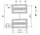
なお、本実施形態に係るレーザー集光装置10においては、光軸ずれの誤差を考慮して、光ファイバー14のコア30の幅方向(矢印X方向)における断面寸法を幅110μm、高さ20μmとし、クラッド32を含めた光ファイバー14全体の断面寸法を幅130μm、高さ40μmとしている。 In the
こうして、光ファイバー14に入射されたレーザー光は、レーザー光出射部18の出射端18Aから出射される。この出射端18Aは、光ファイバー14の幅方向(矢印X方向)の断面形状が矩形型形状であることから、高さ方向に複数本(この場合は48本)、隙間無く密に積層して束ねることが容易にでき、全体で光密度の高いバンドル部28を構成することができる。 Thus, the laser light incident on the
これを具体的な寸法(数値)を用いて説明すると、図3で示すように、幅130μm、高さ40μmの断面寸法を有する光ファイバー14のレーザー光出射部18を、高さ方向に密に48本積み重ねると、そのレーザー光出射部18における出射端18Aのコア30の断面寸法は、幅110μm、高さ1.88mm(1880μm)となる。 This will be described using specific dimensions (numerical values). As shown in FIG. 3, the laser
もし、同じ効果を、一般的に用いられる円形状の光ファイバー(図示省略)で得ようとすると、コア径φ300μmの断面寸法が必要となり、クラッドも含めると、円形状光ファイバーの断面寸法は更に大きいものになる。この円形状光ファイバーを、矩形状光ファイバー14と同数(48本)密に束ねてバンドル部28とすることを想定すると、矩形状光ファイバー14の方が、光密度が高いことは明白である。 If the same effect is to be obtained with a generally used circular optical fiber (not shown), a cross-sectional dimension of a core diameter of φ300 μm is required, and the cross-sectional dimension of the circular optical fiber is even larger when the cladding is included. become. Assuming that this circular optical fiber is bundled in the same number (48) as the rectangular
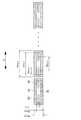
なお、バンドル部28の光密度を更に高める他の方法としては、図4で示すように、バンドル部28とされている出射端18A付近における光ファイバー14のクラッド32を、エッチング等により、数μmを残して除去し、その出射端18A付近のクラッド32の厚さを、他の部分(他の領域)のクラッド32の厚さよりも薄くする方法がある。これにより、コア30の充填率が一層高くなり、光密度を更に高めることができる。 As another method for further increasing the light density of the
具体的には、図4で示すように、光ファイバー14のバンドル化される出射端18A付近において、片側10μmとされているクラッド32を、エッチング等により、約8μm除去する。つまり、出射端18A付近のクラッド32の厚さを約2μmにする。すると、出射端18A付近での光ファイバー14の断面寸法は、幅114μm、高さ24μmとなる。 Specifically, as shown in FIG. 4, about 8 μm of the clad 32 that is 10 μm on one side is removed by etching or the like in the vicinity of the
このような構成の出射端18Aを備えた光ファイバー14のレーザー光出射部18を、図3で示したものと同様に、高さ方向に48本密に束ねてバンドル部28とすると、レーザー光出射部18の出射端18Aにおけるコア30の断面寸法は、幅110μm、高さ1.148mm(1148μm)となり、光密度は明らかに高くなる。 When the laser
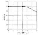
一般に、光の長距離伝送を目的とする光ファイバー14のクラッド32は、全長に亘って透過率を維持するため、相応の厚さを必要とする。例えば本実施例では、クラッド32の厚さを10μmとしている。しかしながら、図5で示すように、例えば全長1mの矩形状光ファイバー14において、その出射端18Aから20mmまでの領域をエッチングして、その領域だけクラッド32の厚さを2μmとしても、光ファイバー14の透過率は98%を維持し、殆ど影響が出ない。 In general, the clad 32 of the
これに対し、例えば全長1mの矩形状光ファイバー14の全長に亘ってクラッド32の厚さを2μmとした場合には、光ファイバー14の透過率は35%となり、光の損失が格段に増加する(透過率が悪化してしまう)ことが確認されている。したがって、クラッド32を除去する部位は、光ファイバー14のレーザー光出射部18における出射端18A付近のみという限られた領域であることが重要で、その領域内(本実施例の場合は出射端18Aから20mm以内)であれば、透過率が悪化するおそれはない。 On the other hand, for example, when the thickness of the
また、上記実施例では、1つの発光点20に対して1本の光ファイバー14で受光するする例を示したが、光ファイバー14の幅寸法のみを大きくすることで、1本の光ファイバー14で複数の発光点20を同時に受光することも可能である。これにより、光ファイバー14の数量を減らすことができるので、部品点数を削減することができ、光軸調整も更に容易に実行できるようになる。 In the above embodiment, an example in which light is received by one
図6はその実施例を示したもので、同時に2つの発光点20からのレーザー光を1本の光ファイバー14で受光するようにした例である。具体的には、光ファイバー14のコア30の幅寸法を310μmとすれば、100μm間隔で置かれた幅100μmの2つの発光点20を1本の光ファイバー14で同時に受光することができる。これによれば、半導体レーザーバー12の全ての発光点20を、24本の光ファイバー14で受光できることになる。 FIG. 6 shows an embodiment thereof, in which laser light from two light emitting
また、バンドル部28は、図7で示すように、光ファイバー14の配置によって、様々な形状とすることができる。例えば、階段状に積層された複数のバンドル部28に分割することも可能であるし、逆に複数のレーザー集光装置10からの光ファイバー14を全て束ねて、1つのバンドル部28とすることもできる。このように、レーザー光出射部18は、その配列を任意かつ容易に変更することができ、出射パターンを任意に形成することができる。 Moreover, the
10 レーザー集光装置
12 半導体レーザーバー
14 光ファイバー
16 レーザー光入射部
16A 入射端
18 レーザー光出射部
18A 出射端
20 発光点
22 保持部材
24 収納溝
26 カバー
28 バンドル部
30 コア
32 クラッドDESCRIPTION OF
Claims (5)
Translated fromJapanese前記レーザーバーの発光点と対向するようにアレイ状に配列され、該レーザーバーから出射されたレーザー光が入射される入射部がシリンドリカルレンズ状に形成されている光ファイバーと、
を備えたことを特徴とするレーザー集光装置。A laser bar having a plurality of light emitting points arranged in an array;
An optical fiber arranged in an array so as to face the light emitting point of the laser bar, and an incident part into which a laser beam emitted from the laser bar is incident is formed in a cylindrical lens shape;
A laser condensing device comprising:
Priority Applications (1)
| Application Number | Priority Date | Filing Date | Title |
|---|---|---|---|
| JP2007040435AJP2008203598A (en) | 2007-02-21 | 2007-02-21 | Laser concentrator |
Applications Claiming Priority (1)
| Application Number | Priority Date | Filing Date | Title |
|---|---|---|---|
| JP2007040435AJP2008203598A (en) | 2007-02-21 | 2007-02-21 | Laser concentrator |
Publications (1)
| Publication Number | Publication Date |
|---|---|
| JP2008203598Atrue JP2008203598A (en) | 2008-09-04 |
Family
ID=39781162
Family Applications (1)
| Application Number | Title | Priority Date | Filing Date |
|---|---|---|---|
| JP2007040435APendingJP2008203598A (en) | 2007-02-21 | 2007-02-21 | Laser concentrator |
Country Status (1)
| Country | Link |
|---|---|
| JP (1) | JP2008203598A (en) |
Cited By (5)
| Publication number | Priority date | Publication date | Assignee | Title |
|---|---|---|---|---|
| JP2012042819A (en)* | 2010-08-20 | 2012-03-01 | Fujikura Ltd | Laser diode module and laser source |
| CN111308725A (en)* | 2020-04-02 | 2020-06-19 | 杭州欧镭激光技术有限公司 | Light beam shaping device for laser radar and shaping method of far-field light spot |
| US10710455B2 (en) | 2013-08-27 | 2020-07-14 | Automotive Coalition For Traffic Safety | Systems and methods for controlling vehicle ignition using biometric data |
| US11001142B2 (en) | 2011-08-29 | 2021-05-11 | Automotive Coalition For Traffic Safety, Inc. | System for non-invasive measurement of an analyte in a vehicle driver |
| US11513070B2 (en) | 2019-06-12 | 2022-11-29 | Automotive Coalition For Traffic Safety, Inc. | System for non-invasive measurement of an analyte in a vehicle driver |
- 2007
- 2007-02-21JPJP2007040435Apatent/JP2008203598A/enactivePending
Cited By (7)
| Publication number | Priority date | Publication date | Assignee | Title |
|---|---|---|---|---|
| JP2012042819A (en)* | 2010-08-20 | 2012-03-01 | Fujikura Ltd | Laser diode module and laser source |
| US11001142B2 (en) | 2011-08-29 | 2021-05-11 | Automotive Coalition For Traffic Safety, Inc. | System for non-invasive measurement of an analyte in a vehicle driver |
| US10710455B2 (en) | 2013-08-27 | 2020-07-14 | Automotive Coalition For Traffic Safety | Systems and methods for controlling vehicle ignition using biometric data |
| US11513070B2 (en) | 2019-06-12 | 2022-11-29 | Automotive Coalition For Traffic Safety, Inc. | System for non-invasive measurement of an analyte in a vehicle driver |
| US11971351B2 (en) | 2019-06-12 | 2024-04-30 | Automotive Coalition For Traffic Safety, Inc. | System for non-invasive measurement of an analyte in a vehicle driver |
| CN111308725A (en)* | 2020-04-02 | 2020-06-19 | 杭州欧镭激光技术有限公司 | Light beam shaping device for laser radar and shaping method of far-field light spot |
| CN111308725B (en)* | 2020-04-02 | 2023-11-14 | 杭州欧镭激光技术有限公司 | Beam shaping device for laser radar and shaping method of beam shaping device for laser radar on far-field light spots |
Similar Documents
| Publication | Publication Date | Title |
|---|---|---|
| US6757106B2 (en) | Optical lens, optical lens unit, stacked type optical lens, optical system and semiconductor laser apparatus | |
| US8942521B2 (en) | Planar waveguide element | |
| JP5831403B2 (en) | Coupling optical system and coupling method | |
| EP1703601A1 (en) | Fiber laser oscillator | |
| US9001850B2 (en) | Excitation unit for a fiber laser | |
| JP2008203598A (en) | Laser concentrator | |
| WO2006129872A1 (en) | Combined light source | |
| JP2004070339A (en) | Optical fiber coupler capable of relaxing alignment tolerance | |
| US6973234B2 (en) | Optical circuit for condensing laser beams, and light source device | |
| JP3994961B2 (en) | Optical waveguide array and laser light emitting device | |
| JP5725176B2 (en) | Light guide device and light guide method | |
| WO2006129774A1 (en) | Multimode optical combiner and process for producing the same | |
| US6400745B1 (en) | Laser radiating optical system | |
| JP5885782B2 (en) | Optical system | |
| JP5277959B2 (en) | Optical fiber array, semiconductor laser condensing device, and optical fiber array manufacturing method | |
| JP2002374031A (en) | Focusing system for semiconductor laser | |
| JP2004361655A (en) | Laser focusing device | |
| JP5065195B2 (en) | Optical module and manufacturing method thereof | |
| CN118276239A (en) | Waveguide and electromagnetic spectrometer | |
| JP2008065306A (en) | Multibeam generating element and optical recording apparatus using multibeam | |
| JP2004361837A (en) | Optical waveguide, optical waveguide array and laser light emitting device | |
| JP2004354597A (en) | Optical waveguide, optical waveguide array, and laser light emitting device | |
| JP6477209B2 (en) | Combined laser light source and fiber adjustment method | |
| KR100858672B1 (en) | Fiber optic unit | |
| JP2002023023A (en) | Focusing optics |