JP2008201564A - Belt rotation device and image forming device - Google Patents
Belt rotation device and image forming deviceDownload PDFInfo
- Publication number
- JP2008201564A JP2008201564AJP2007042246AJP2007042246AJP2008201564AJP 2008201564 AJP2008201564 AJP 2008201564AJP 2007042246 AJP2007042246 AJP 2007042246AJP 2007042246 AJP2007042246 AJP 2007042246AJP 2008201564 AJP2008201564 AJP 2008201564A
- Authority
- JP
- Japan
- Prior art keywords
- belt
- pair
- rib
- ribs
- width direction
- Prior art date
- Legal status (The legal status is an assumption and is not a legal conclusion. Google has not performed a legal analysis and makes no representation as to the accuracy of the status listed.)
- Pending
Links
Images


Landscapes
- Handling Of Sheets (AREA)
- Delivering By Means Of Belts And Rollers (AREA)
Abstract
Description
Translated fromJapanese本発明は、ベルト回転装置、及びベルト回転装置を備える画像形成装置に関する。 The present invention relates to a belt rotating device and an image forming apparatus including the belt rotating device.
インクジェット式の画像形成装置等において搬送装置や中間転写装置等として機能するベルト回転装置では、ベルトが複数の張架ローラにより張架されることによって、ベルトにしわが発生し、ベルト上の用紙またはベルト自体に形成される画質が低下する場合がある。このため、複数の張架ローラにより張架されたベルトに発生するしわを抑制することを目的とした構成が考案されている(例えば、特許文献1乃至特許文献3参照)。 In a belt rotating device that functions as a conveying device, an intermediate transfer device, or the like in an ink jet image forming apparatus or the like, the belt is stretched by a plurality of stretching rollers, so that the belt is wrinkled, and the paper on the belt or the belt There is a case where the image quality formed in itself deteriorates. For this reason, the structure aiming at suppressing the wrinkle which generate | occur | produces in the belt stretched by the several tension roller is devised (for example, refer patent document 1 thru | or patent document 3).
特許文献1記載の構成は、プラテンを張架ローラよりもヘッド側に配置する(高くする)というものである。この構成では、ベルトの幅方向外側部に発生するしわに対しては抑制効果が発揮されるが、ベルトの幅方向中央部に発生するしわに対しては十分な抑制効果が発揮されないという問題がある。 The configuration described in Patent Document 1 is such that the platen is disposed (higher) on the head side than the tension roller. In this configuration, the effect of suppressing wrinkles that occur in the outer portion of the belt in the width direction is exhibited, but there is a problem that the effect of suppressing the wrinkles that occur in the central portion in the width direction of the belt is not sufficiently exhibited. is there.
また、特許文献2記載の構成は、ベルトを幅方向外側に付勢するローラを配設するというものである。この構成では、離散的にしかベルトに付勢力を加えることができないため、ローラの近傍で発生するしわに対しては抑制効果が発揮されるが、ローラから離れた位置で発生するしわに対しては十分な抑制効果が発揮されないという問題がある。 The configuration described in
また、特許文献3記載の構成は、ベルトとプラテンとを電気力により吸着させるというものである。この構成では、ベルトとプラテンとの吸着力が、環境変動に対して不安定であるため、ベルトに発生するしわに対する抑制効果が安定的に発揮されないという問題がある。
本発明は上記事実を考慮してなされたものであり、複数の張架ローラにより張架されたベルトに発生するしわに対する抑制効果を、ベルト幅方向及びベルト回転方向に亘って満遍なく、且つ安定的に発揮可能なベルト回転装置を提供することを目的とする。 The present invention has been made in consideration of the above-described facts, and the effect of suppressing wrinkles generated in a belt stretched by a plurality of stretch rollers is uniform and stable in the belt width direction and the belt rotation direction. It is an object of the present invention to provide a belt rotating device that can be applied to the above.
請求項1に記載のベルト回転装置は、無端状のベルトと、前記ベルトを張架し回転させる複数の張架ローラと、前記ベルトの内周面の幅方向両端側にベルト回転方向に沿って並列され、全体若しくは一部を弾性部材により構成された一対のリブと、一対の前記リブ間に前記リブに沿って並列され、一対の前記リブの離間距離よりも離間距離を大きくされた一対のガイド手段と、を有することを特徴とする。 The belt rotating device according to claim 1 is an endless belt, a plurality of stretching rollers that stretch and rotate the belt, and both ends of the inner peripheral surface of the belt in the width direction along the belt rotating direction. A pair of ribs that are arranged in parallel and partially or entirely made of an elastic member, and a pair of ribs that are arranged in parallel along the rib between the pair of ribs, and whose separation distance is larger than the separation distance of the pair of ribs. And a guide means.
請求項1に記載のベルト回転装置では、無端状のベルトが、複数の張架ローラにより張架され回転される。この無端状のベルトの内周面の幅方向両端側には、一対のリブがベルト回転方向に沿って並列され、一対のリブ間には、一対のガイド手段がリブに沿って並列されている。 In the belt rotating device according to the first aspect, the endless belt is stretched and rotated by a plurality of stretching rollers. A pair of ribs are juxtaposed along the belt rotation direction on both ends in the width direction of the inner peripheral surface of the endless belt, and a pair of guide means are juxtaposed along the ribs between the pair of ribs. .
ここで、一対のリブは、全体若しくは一部を弾性部材により構成されており、また、一対のガイド手段の離間距離は、一対のリブの離間距離よりも大きくされている。このため、一対のリブが、全体若しくは一部を弾性変形させて一対のガイド手段に嵌る。 Here, the pair of ribs is entirely or partly constituted by an elastic member, and the distance between the pair of guide means is larger than the distance between the pair of ribs. Therefore, the pair of ribs are elastically deformed in whole or in part and fit into the pair of guide means.
これにより、一対のリブからベルトに対して、ベルト幅方向外側への張力がベルト回転方向へ連続的に与えられる。よって、複数の張架ローラにより張架されたベルトに発生するしわに対する抑制効果を、ベルト幅方向及びベルト回転方向に亘って満遍なく、且つ安定的に発揮可能である。 Thereby, the tension | tensile_strength to the belt width direction outer side is continuously given to a belt rotation direction with respect to a belt from a pair of rib. Therefore, the effect of suppressing wrinkles generated in a belt stretched by a plurality of stretch rollers can be exhibited evenly and stably over the belt width direction and the belt rotation direction.
請求項2に記載のベルト回転装置は、請求項1に記載のベルト回転装置であって、前記リブのベルト外周側への移動を規制する移動規制手段を有することを特徴とする。 A belt rotation device according to a second aspect of the present invention is the belt rotation device according to the first aspect, further comprising movement restriction means for restricting movement of the rib toward the belt outer peripheral side.
請求項2に記載のベルト回転装置では、移動規制手段により、リブのベルト外周側への移動が規制されることにより、リブのガイド手段からの離脱が防止される。よって、複数の張架ローラにより張架されたベルトに発生するしわに対する抑制効果を、確実に発揮可能である。 In the belt rotating device according to the second aspect, the movement of the ribs from the guide means is prevented by restricting the movement of the ribs toward the belt outer peripheral side by the movement restricting means. Therefore, the effect of suppressing wrinkles generated in the belt stretched by a plurality of stretching rollers can be reliably exhibited.
請求項3に記載のベルト回転装置は、請求項2に記載のベルト回転装置であって、前記移動規制手段は、前記リブのベルト幅方向内側に形成され、ベルト外周側から内周側へかけてベルト幅方向外側から内側へ傾斜するテーパ部であることを特徴とする。 The belt rotating device according to claim 3 is the belt rotating device according to
請求項3に記載のベルト回転装置では、リブのベルト幅方向内側に、ベルト外周側から内周側へかけてベルト幅方向外側から内側へ傾斜するテーパ部が形成されており、このテーパ部により、リブのベルト外周側への移動が規制される。 In the belt rotating device according to claim 3, a taper portion is formed on the inner side in the belt width direction of the rib so as to incline from the outer side of the belt to the inner peripheral side. The movement of the rib to the belt outer peripheral side is restricted.
また、このテーパ部からベルトに対して、ベルト幅方向内側から外側へかけてベルト外周側から内周側へ傾斜した方向への張力が与えられ、ベルトがベルト内周側へ付勢されるため、ベルトのベルト外周側への浮き上がりに対する抑制効果を、より効果的に発揮可能である。 In addition, tension is applied to the belt from the taper portion to the belt from the inner side to the outer side in the belt width direction, so that the belt is biased toward the inner peripheral side of the belt. In addition, it is possible to more effectively exert the effect of suppressing the lifting of the belt to the belt outer peripheral side.
請求項4に記載のベルト回転装置は、請求項1乃至請求項3の何れか1項に記載のベルト回転装置であって、前記リブと前記ベルトとの接合部を弾性部材により構成したことを特徴とする。 The belt rotation device according to claim 4 is the belt rotation device according to any one of claims 1 to 3, wherein a joint portion between the rib and the belt is formed of an elastic member. Features.
請求項4に記載のベルト回転装置では、リブとベルトとの接合部が弾性部材により構成されており、一対のリブは、該接合部を弾性変形させて一対のガイド手段に嵌る。これにより、リブのガイド手段との当接部を剛体とすることが可能であり、よって、リブの磨耗を抑制可能である。 In the belt rotating device according to the fourth aspect, the joint portion between the rib and the belt is formed by an elastic member, and the pair of ribs are fitted into the pair of guide means by elastically deforming the joint portion. Thereby, it is possible to make the contact portion of the rib with the guide means a rigid body, and therefore, wear of the rib can be suppressed.
請求項5に記載の画像形成装置は、請求項1乃至請求項4の何れか1項に記載のベルト回転装置を備えており、前記ベルトは、一対の前記ガイド手段を一対の前記リブ間に備える弦部により記録媒体を保持して搬送する搬送ベルトであり、前記搬送ベルトにより搬送される記録媒体に画像を形成する画像形成手段を有することを特徴とする。 An image forming apparatus according to a fifth aspect includes the belt rotating device according to any one of the first to fourth aspects, wherein the belt includes a pair of guide means between the pair of ribs. A conveying belt that holds and conveys a recording medium by a string portion provided therein, and has an image forming unit that forms an image on the recording medium conveyed by the conveying belt.
請求項5に記載の画像形成装置では、搬送ベルトのある弦部が、一対のリブガイドに嵌った一対のリブからベルト幅方向外側への張力を受ける。該弦部は、記録媒体を保持して搬送し、画像形成手段が、該弦部により搬送される記録媒体に画像を形成する。ここで、搬送ベルトの記録媒体の搬送を行う弦部は、リブからベルト幅方向外側への張力を受けることにより、しわの発生を抑制される。 In the image forming apparatus according to the fifth aspect, the chord portion having the conveying belt receives tension toward the outside in the belt width direction from the pair of ribs fitted to the pair of rib guides. The string portion holds and conveys the recording medium, and the image forming unit forms an image on the recording medium conveyed by the string portion. Here, the chord portion that conveys the recording medium of the conveyance belt receives a tension from the rib to the outside in the belt width direction, thereby suppressing the generation of wrinkles.
よって、画像形成中の記録媒体の平面性、及び記録媒体と画像形成手段との位置精度(クリアランスの精度)を向上でき、以って、画像形成手段により記録媒体に形成される画像の品質を向上できる。 Therefore, it is possible to improve the flatness of the recording medium during image formation and the positional accuracy (clearance accuracy) between the recording medium and the image forming means, thereby improving the quality of the image formed on the recording medium by the image forming means. Can be improved.
請求項6に記載の画像形成装置は、請求項1乃至請求項4の何れか1項に記載のベルト回転装置を備えており、前記ベルトの一対の前記ガイド手段を一対の前記リブ間に備える弦部に画像を形成する画像形成手段と、前記画像形成手段により前記ベルトに形成された画像を記録媒体に転写させる転写手段と、を有することを特徴とする。 An image forming apparatus according to a sixth aspect includes the belt rotating device according to any one of the first to fourth aspects, wherein the pair of guide means of the belt is provided between the pair of ribs. An image forming unit that forms an image on the string portion, and a transfer unit that transfers the image formed on the belt by the image forming unit to a recording medium.
請求項6に記載の画像形成装置では、ベルトのある弦部が、一対のリブガイドに嵌った一対のリブからベルト幅方向外側への張力を受ける。該弦部は、画像形成手段により画像形成を行われる。ここで、ベルトの画像形成が行われる弦部は、リブからベルト幅方向外側への張力を受けることにより、しわの発生を抑制される。 According to another aspect of the image forming apparatus of the present invention, the chord portion having the belt receives tension toward the outside in the belt width direction from the pair of ribs fitted to the pair of rib guides. The string portion is image-formed by image forming means. Here, the string portion where the image of the belt is formed receives the tension from the rib to the outside in the belt width direction, thereby suppressing the generation of wrinkles.
よって、ベルトの平面性、及びベルトと画像形成手段との位置精度(クリアランスの精度)を向上でき、以って、画像形成手段によりベルトに形成される画像の品質を向上できる。 Therefore, the flatness of the belt and the positional accuracy (clearance accuracy) between the belt and the image forming unit can be improved, and thus the quality of the image formed on the belt by the image forming unit can be improved.
以上説明したように、本発明によれば、複数の張架ローラにより張架されたベルトに発生するしわに対する抑制効果を、ベルト幅方向及びベルト回転方向に亘って満遍なく、且つ安定的に発揮可能なベルト回転装置を提供可能である。 As described above, according to the present invention, the effect of suppressing wrinkles generated in a belt stretched by a plurality of stretching rollers can be exerted evenly and stably over the belt width direction and the belt rotation direction. A simple belt rotating device can be provided.
以下、図面を参照して本発明の実施形態について説明する。なお、ベルトの回転方向(以下、ベルト回転方向という)を図中矢印Xで示し、ベルトの回転方向と直交する方向(以下、ベルト幅方向という)を図中矢印Yで示している。 Hereinafter, embodiments of the present invention will be described with reference to the drawings. Note that the belt rotation direction (hereinafter referred to as belt rotation direction) is indicated by an arrow X in the drawing, and the direction orthogonal to the belt rotation direction (hereinafter referred to as belt width direction) is indicated by an arrow Y in the drawing.
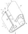
図1には、本発明のベルト回転装置の第1実施形態に係る搬送装置10を備える画像形成装置としてのインクジェット記録装置12が示されている。インクジェット記録装置12には、給紙トレイ(図示省略)が備えられており、給紙トレイ内に積層された用紙Pが、1枚ずつ取り出され、所定の搬送経路を構成する複数の搬送ローラ対(1個のみ図示)16により搬送される。 FIG. 1 shows an ink
該搬送ローラ対16の搬送方向下流側には、搬送装置10が配設されている。この搬送装置10は、無端状のベルトとしての搬送ベルト18と、搬送ベルト18を三角形状に張架する張架ローラとしての駆動ローラ20及び従動ローラ22、23とを備えている。 A
駆動ローラ20及び従動ローラ22は、略水平に配設され、従動ローラ23は、搬送ベルト18の上側弦部(上側の張られた部分)18Aの下方に配設されている。また、駆動ローラ20は、従動ローラ22の搬送方向下流側に配設されており、モータ(図示省略)により駆動され、搬送ベルト18を摩擦力により回転させる。従動ローラ22、23は、駆動ローラ20により回転される搬送ベルト18に従動して回転する。 The
また、搬送ベルト18の上方には画像形成手段としての記録ヘッドアレイ30が配置されており、搬送ベルト18の上側弦部18Aに対向している。この対向した領域が、記録ヘッドアレイ30からインク滴が吐出される吐出領域SEとなっている。用紙Pは、搬送ベルト18で保持されてこの吐出領域SEに至り、記録ヘッドアレイ30に対向した状態で、記録ヘッドアレイ30から画像情報に応じたインク滴を付着される。 A
記録ヘッドアレイ30は、本実施形態では、有効な記録領域が用紙Pの幅(搬送方向と直交する方向の長さ)以上とされた長尺状とされ、イエロー(Y)、マゼンタ(M)、サイアン(C)、及びブラック(K)の4色それぞれに対応した4つのインクジェット記録ヘッド(以下、記録ヘッドという)32が搬送方向に沿って配置されており、フルカラーの画像を記録可能になっている。 In this embodiment, the
各記録ヘッド32は、ヘッド駆動回路(図示省略)によって駆動される。ヘッド駆動回路は、たとえば、画像情報に応じてインク滴の吐出タイミングや使用するインク吐出口(ノズル)を決め、駆動信号を記録ヘッド32に送る構成である。 Each
また、記録ヘッドアレイ30の搬送方向上流側には、電源38が接続された帯電ローラ36が配置されている。帯電ローラ36は、従動ローラ22と共に搬送ベルト18及び用紙Pを挟んだ状態で、従動ローラ22に従動し、用紙Pを搬送ベルト18に押圧する。この際、接地された従動ローラ22と帯電ローラ36とに所定の電位差が生じることにより、用紙Pが、電荷を付与されて搬送ベルト18に静電吸着する。 A charging
また、記録ヘッドアレイ30の搬送方向下流側には、剥離プレート40が配置されており、用紙Pを搬送ベルト18から剥離させる。剥離された用紙Pは、剥離プレート40の搬送方向下流側で複数の排出ローラ対(図示省略)により搬送され機外へ排出される。 Further, a peeling
ここで、搬送装置10の構成について説明する。 Here, the configuration of the
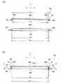
図1乃至図3に示すように、搬送装置10は、プラテン24を備えている。プラテン24の上面24Aは、搬送ベルト18の上側弦部18Aの内周面に接すると共に、上側弦部18Aを挟んで記録ヘッド32に対向して配設されている。また、プラテン24の上面24Aには、フッ素樹脂のオーバーコート処理等の、搬送ベルト18との摩擦係数を低減するための処理が施されている。 As shown in FIGS. 1 to 3, the
搬送ベルト18の幅方向両端部には、断面矩形状の一対のリブ42が、ベルト回転方向に沿って配設されている。このリブ42は、無端状に構成され、もしくは長手方向一端部と他端部とを結合されることにより環状に構成され、ベルト回転方向に1周している。 A pair of
また、プラテン24のベルト幅方向両端部には、上側弦部18Aの反対側へ凹とされた一対の段差部24Bが形成され、上面24Aのベルト幅方向両端部の一対の端面が、ガイド手段としての一対のリブガイド44とされており、一対のリブガイド44が、一対のリブ42の間に配設されている。 In addition, a pair of stepped
ここで、搬送ベルト18は高弾性材料(例えば、ポリイミド、弾性率E=70MPa)により、リブ42は、低弾性材料(例えば、ゴム系材料、弾性率E=0.2MPa)により構成されている。また、リブガイド44(プラテン24)は、剛体(例えば、アルミ、弾性率E=70GPa)により構成されている。 Here, the
なお、搬送ベルト18の弾性率Eb、リブ42の弾性率Er、リブガイド44の弾性率Egは、下記(1)、(2)式を満足する必要がある。 The elastic modulus Eb of the conveying
Eb>Er…(1)
Eg>Er…(2)Eb> Er (1)
Eg> Er (2)
また、図3(B)に示すように、一対のリブ42の離間距離(ベルト幅方向の距離)Lbは、一対のリブガイド44の離間距離(ベルト幅方向の距離)Lgよりも短くされており、一対のリブ42は、弾性変形して一対のリブガイド44に(上面24Aのベルト幅方向両端部に)嵌っている。 As shown in FIG. 3B, the separation distance (distance in the belt width direction) Lb of the pair of
また、一対のリブ42の離間距離Lbは、駆動ローラ20及び従動ローラ22、23のローラ部の軸長(ベルト幅方向長さ)Lrよりも長くされており、駆動ローラ20及び従動ローラ22、23は、一対のリブ42に非接触とされている。 The separation distance Lb between the pair of
ところで、図4に示すように、一対のリブ42及び一対のリブガイド44を備えないベルト回転装置1においては、搬送ベルト18の上側弦部18Aにおいて、駆動ローラ20及び従動ローラ22からテンションPを受けることにより、ベルト幅方向に延びるしわが発生する。 Incidentally, as shown in FIG. 4, in the belt rotating device 1 that does not include the pair of
次に、本実施形態における作用について説明する。 Next, the operation in this embodiment will be described.
図3(A)に示すように、弾性部材(低弾性材料)により形成された一対のリブ42が、弾性変形して一対のリブガイド44に嵌っていることにより、一対のリブ42から搬送ベルト18の幅方向両端部に対して、ベルト幅方向外側への張力Fがベルト回転方向へ連続的に与えられる。 As shown in FIG. 3A, the pair of
よって、駆動ローラ20及び従動ローラ22、23により張架された搬送ベルト18に発生するしわに対する抑制効果を、ベルト幅方向及びベルト回転方向に亘って満遍なく発揮可能である。また、搬送ベルト18とプラテン24とを電気力により吸着(静電吸着)させる場合と比較して、環境変動に対する安定性を向上可能である。 Therefore, the effect of suppressing wrinkles generated on the conveying
従って、画像形成中の用紙Pの平面性、及び用紙Pと記録ヘッド32との位置精度(クリアランスの精度)を向上でき、以って、記録ヘッド32により用紙Pに形成される画像の品質を向上できる。 Accordingly, the flatness of the paper P during image formation and the positional accuracy (clearance accuracy) between the paper P and the
また、一対のリブ42が一対のリブガイド44に当接することによって、搬送ベルト18の幅方向への移動(所謂ウォーク)が抑制されるので、記録ヘッド32により用紙Pに形成される画像の品質をより一層向上できる。 Further, since the pair of
また、駆動ローラ20及び従動ローラ22、23が、一対のリブ42に非接触とされていることによって、駆動ローラ20及び従動ローラ22、23とリブ42との接触に起因する諸問題、例えば、駆動ローラ20及び従動ローラ22、23によりリブ42が弾性変形され、リブ42がリブガイド44と非接触になり、しわの抑制効果が発揮不能になる等の問題の発生を防止できる。 Further, since the driving
なお、例えば、Lb=300mm、Lg=302mm、Er=0.2MPa、Eb=70MPa、Eg=70GPa、リブ42とリブガイド44との接触幅A=2mm×300mm=600、リブ42の幅Sr=5mmとした場合、リブ42の縮み量λ(mm)、リブ42が縮んだ際に発生する圧縮応力による張力F(N)は、以下のようになる。 For example, Lb = 300 mm, Lg = 302 mm, Er = 0.2 MPa, Eb = 70 MPa, Eg = 70 GPa, the contact width A = 2 mm × 300 mm = 600 between the
λ=(Lg−Lb)/2=(302−300)/2=1(mm)
F=(ErλA)/Sr=ErA(Lg−Lb)/2Sr
=(0.2×106×1×10−3×6×10−4)/5×10−3=120(N)
≒12.2(kgf)λ = (Lg−Lb) / 2 = (302−300) / 2 = 1 (mm)
F = (ErλA) / Sr = ErA (Lg−Lb) / 2Sr
= (0.2 × 106 × 1 × 10−3 × 6 × 10−4 ) / 5 × 10−3 = 120 (N)
≒ 12.2 (kgf)
この設定では、搬送ベルト18が座屈してしわが発生する瞬間のベルト回転方向の張力Pを、12kgf程度まで許容可能である。 In this setting, the tension P in the belt rotation direction at the moment when the
次に、本発明のベルト回転装置の第2実施形態について説明する。なお、第1実施形態と同様の構成には同一の符号を付し、説明は省略する。 Next, a second embodiment of the belt rotating device of the present invention will be described. In addition, the same code | symbol is attached | subjected to the structure similar to 1st Embodiment, and description is abbreviate | omitted.
図5(A)、(B)には、本発明の第2実施形態に係る搬送装置50が示されている。この図に示すように、搬送装置50は、第1実施形態におけるリブ42に替えてリブ52を備え、第1実施形態におけるプラテン24に替えてプラテン54を備えている。 5A and 5B show a
リブ52は、搬送ベルト18の幅方向両端部に接合された断面矩形状の本体部52Aと、本体部52Aのベルト内周側端部からベルト幅方向内側へ延設された断面薄板状の係合片52Bとを備えている。 The
また、プラテン54の上面54Aのベルト幅方向両端部の一対の端面が、一対のリブガイド44とされている。一対のリブ52は、本体部52Aを弾性変形させて一対のリブガイド44に嵌っている。 In addition, a pair of end surfaces at both end portions in the belt width direction of the
ここで、リブガイド44の反上側弦部18A側には、ベルト幅方向内側へ凹とされた係合凹部54Bが形成されている。この係合凹部54Bと上述の係合片52Bとは、上側弦部18Aと上面54Aとが当接した状態で係合可能とされており、これらにより、移動規制手段としての移動規制部56が構成されている。 Here, an engaging recess 54B that is recessed inward in the belt width direction is formed on the side of the
次に、本実施形態における作用について説明する。 Next, the operation in this embodiment will be described.
一対のリブ52が、本体部52Aを弾性変形させて一対のリブガイド44に嵌っていることにより、一対のリブ52から搬送ベルト18の幅方向両端部に対して、ベルト幅方向外側への張力Fが与えられる。 The pair of
また、係合凹部54Bと上述の係合片52Bとが、上側弦部18Aと上面54Aとが当接した状態で係合することにより、リブ52のベルト外周側への移動が制限(阻止)され、リブ52のリブガイド54からの離脱が阻止される。 Further, the engagement recess 54B and the above-described
よって、駆動ローラ20及び従動ローラ22、23により張架された搬送ベルト18に発生するしわに対する抑制効果を、確実に発揮可能である。 Therefore, the effect of suppressing wrinkles generated on the conveying
次に、本発明のベルト回転装置の第3実施形態について説明する。なお、第1及び第2実施形態と同様の構成には同一の符号を付し、説明は省略する。 Next, a third embodiment of the belt rotating device of the present invention will be described. In addition, the same code | symbol is attached | subjected to the structure similar to 1st and 2nd embodiment, and description is abbreviate | omitted.
図6(A)、(B)には、本発明の第3実施形態に係る搬送装置60が示されている。この図に示すように、搬送装置60は、第1実施形態におけるリブ42に替えてリブ62を備え、第1実施形態におけるプラテン24に替えてプラテン64を備えている。 6A and 6B show a
リブ62は、断面台形状に構成されており、ベルト外周側から内周側へかけてベルト幅方向外側から内側へ傾斜したテーパ部62Aを、ベルト幅方向内側に備えている。 The
また、プラテン64の上面64Aのベルト幅方向両端部の一対の端面が、一対のガイド手段としてのリブガイド66とされている。一対のリブガイド66は、ベルト内周側から外周側へかけてベルト幅方向内側から外側へ傾斜している。 Further, a pair of end surfaces at both ends in the belt width direction of the
一対のリブ62の最小離間距離LbMINは、一対のリブガイド66の最小離間距離LgMINよりも短くされ、また、一対のリブ62の最大離間距離LbMAXは、一対のリブガイド66の最大離間距離LgMAXよりも短くされており、一対のリブ62が、全体を弾性変形させて一対のリブガイド66に嵌っている。The minimum separation distance LbMIN of the pair of
また、図6(B)に示すように、一対のリブ62が一対のリブガイド66に嵌った状態において、一対のリブガイド66の最大離間距離LgMAXが、一対のリブ62の最小離間距離LbMINよりも短くされている。Further, as shown in FIG. 6B, in the state where the pair of
一対のリブ62と一対のリブガイド66とは、上側弦部18Aと上面64Aとが当接した状態で当接(係合)可能とされており、これらにより、移動規制手段としての移動規制部68が構成されている。 The pair of
次に、本実施形態における作用について説明する。 Next, the operation in this embodiment will be described.
一対のリブ62が、弾性変形して一対のリブガイド66に嵌っていることにより、一対のリブ62から搬送ベルト18の幅方向両端部に対して、ベルト幅方向外側への張力Fが与えられる。 Since the pair of
また、図6(B)に示すように、一対のリブ62が一対のリブガイド66に嵌った状態において、一対のリブガイド66の最大離間距離LgMAXが、一対のリブ62の最小離間距離LbMINよりも長くされていることにより、リブ62のベルト外周側への移動が制限(阻止)され、リブ62のリブガイド64からの離脱が阻止される。Further, as shown in FIG. 6B, in the state where the pair of
また、リブガイド66がベルト内周側から外周側へかけてベルト幅方向内側から外側へ傾斜したテーパ状に構成され、リブガイド66が当接するリブ62のベルト幅方向内側部が、ベルト外周側から内周側へかけてベルト幅方向外側から内側へ傾斜したテーパ部62Aとされていることにより、リブガイド66からリブ62に対して、ベルト幅方向外側へかけてベルト内周側へ傾斜した力が作用する。これにより、リブ62から上側弦部18Aのベルト幅方向両端部に対して、ベルト幅方向外側へかけてベルト内周側へ傾斜した力が作用し、上側弦部18Aがプラテン64の上面64Aに付勢される。よって、上側弦部18Aのプラテン64からの浮き上がりを抑制可能である。 Also, the
なお、本実施形態では、一対のリブガイド66の最大離間距離LgMAXが、一対のリブガイド66に嵌った一対のリブ62の最小離間距離LbMINよりも長くされているが、少なくとも一方のリブガイド66の一部と他方のリブガイド66の一部との離間距離が、一対のリブガイド66に嵌った一対のリブ62の最小離間距離LbMINよりも長くされていればよい。例えば、一対のリブガイド66をベルト厚み方向に対して平行とし、一対のリブガイド66の離間距離を、一対のリブガイド66が嵌った一対のリブ62の最小離間距離LrMINよりも短くした構成も、本実施形態と同様の作用効果を得ることができる。In the present embodiment, the maximum separation distance LgMAX of the pair of rib guides 66 is longer than the minimum separation distance LbMIN of the pair of
次に、本発明のベルト回転装置の第4実施形態について説明する。なお、第1乃至第3実施形態と同様の構成には同一の符号を付し、説明は省略する。 Next, a fourth embodiment of the belt rotating device of the present invention will be described. In addition, the same code | symbol is attached | subjected to the structure similar to 1st thru | or 3rd embodiment, and description is abbreviate | omitted.
図7には、本発明の第3実施形態に係る搬送装置70が示されている。この図に示すように、搬送装置70は、移動規制手段としての一対のリブ押さえローラ72を備えている。一対のリブ押さえローラ72は、上側弦部18Aの外周面の幅方向両端部に、上側弦部18Aを挟んでリブ42及び上面24Aのベルト幅方向両端部に対向して配設されており、上側弦部18Aに従動して回転する。 FIG. 7 shows a
ここで、リブ押さえローラ72の回転中心には円孔が空けられ、この円孔内に、ベルト幅方向に延在する引張りコイルバネ74が挿通されている。リブ押さえローラ72は、引張りコイルバネ74回りに回転可能とされると共に、引張りコイルバネ74により上側弦部18Aのベルト幅方向両端部を介してリブ42及び上面24Aのベルト幅方向両端部に圧接されている。 Here, a circular hole is formed in the rotation center of the
次に、本実施形態における作用について説明する。 Next, the operation in this embodiment will be described.
リブ押さえローラ72が、引張りコイルバネ74により上側弦部18Aのベルト幅方向両端部を介してリブ42に圧接されていることにより、リブ42のリブガイド44からの離脱が阻止される。これにより、搬送ベルト18に発生するしわの抑制効果を確実に発揮可能である。 The
次に、本発明のベルト回転装置の第5実施形態について説明する。なお、第1乃至第4実施形態と同様の構成には同一の符号を付し、説明は省略する。 Next, a fifth embodiment of the belt rotating device of the present invention will be described. In addition, the same code | symbol is attached | subjected to the structure similar to 1st thru | or 4th embodiment, and description is abbreviate | omitted.
図8(A)〜(C)には、本発明の第5実施形態に係る搬送装置80が示されている。この図に示すように、搬送装置80は、第1実施形態におけるリブ42に替えてリブ82を備えている。一対のリブ82は、断面矩形状に構成されており、接合部としての接着層84により搬送ベルト18の幅方向両端部に接着されている。 8A to 8C show a
ここで、搬送ベルト18及びリブ82は、共に高弾性材料(例えば、ポリイミド、弾性率E=70MPa)により、接着層84が、低弾性の接着剤(例えば、ゴム系接着剤、弾性率E=0.2MPa)により構成されている。また、リブガイド44は、剛体(例えば、アルミ、弾性率E=70GPa)により構成されている。 Here, the conveying
なお、このような場合には、搬送ベルト18の弾性率Eb、リブ82の弾性率Er、リブガイド44の弾性率Eg、接着層84の弾性率Eaは、下記(3)〜(5)式を満足する必要がある。 In such a case, the elastic modulus Eb of the conveying
Eb>Ea…(3)
Eg>Ea…(4)
Er>Ea…(5)Eb> Ea (3)
Eg> Ea (4)
Er> Ea (5)
一対のリブ82の離間距離Lrは、第1実施形態と同様とされており、一対のリブ82は、弾性層84を弾性変形させて一対のリブガイド44に嵌っている。 The separation distance Lr between the pair of
次に、本実施形態における作用について説明する。 Next, the operation in this embodiment will be described.
一対のリブ82が弾性層84を弾性変形させて一対のリブガイド44に嵌っていることにより、一対のリブ82から搬送ベルト18の幅方向両端部に対して、ベルト幅方向外側への張力Fが与えられる。これにより、搬送ベルト18に発生するしわに対する抑制効果を、ベルト幅方向及びベルト回転方向に亘って満遍なく発揮可能となる。 By the pair of
また、一対のリブ82が高弾性材料により構成されていることによって、リブ82の磨耗を低減できる。 Further, since the pair of
次に、本発明のベルト回転装置の第6実施形態について説明する。なお、第1乃至第5実施形態と同様の構成には同一の符号を付し、説明は省略する。 Next, a sixth embodiment of the belt rotating device of the present invention will be described. In addition, the same code | symbol is attached | subjected to the structure similar to 1st thru | or 5th embodiment, and description is abbreviate | omitted.
図9には、本発明の第6実施形態に係る搬送装置90が示されている。この図に示すように、搬送装置90は、第1実施形態におけるプラテン24に替えてプラテン92を備えている。プラテン92の上面92Aには、リブ42に面してベルト回転方向に沿って延在する断面矩形状の一対の溝92Bが形成され、溝92Bのベルト幅方向内側の壁面が、リブガイド44とされており、一対のリブガイド44が、一対のリブ42の間に配設されている。第1実施形態と同様に、一対のリブ42は、弾性変形して一対のリブガイド44に嵌っており、本実施形態に係る搬送装置90においても、第1実施形態と同様の作用効果を得ることが可能である。 FIG. 9 shows a transport apparatus 90 according to the sixth embodiment of the present invention. As shown in this figure, the transport apparatus 90 includes a
次に、本発明のベルト回転装置の第7実施形態に係る中間転写装置100について説明する。なお、第1乃至第6実施形態と同様の構成には同一の符号を付し、説明は省略する。 Next, an intermediate transfer device 100 according to a seventh embodiment of the belt rotating device of the present invention will be described. In addition, the same code | symbol is attached | subjected to the structure similar to 1st thru | or 6th embodiment, and description is abbreviate | omitted.
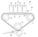
図10には、本実施形態に係る中間転写装置100を備える画像形成装置としてのインクジェット記録装置200が示されている。このインクジェット記録装置200では、記録ヘッドアレイ30の下方に中間転写装置100が備えられている。 FIG. 10 shows an
この中間転写装置100は、無端状のベルトとしての中間転写ベルト116と、中間転写ベルト116を張架する張架ローラとしての駆動ローラ20及び従動ローラ22、23と、中間転写ベルト116の内周側に配設され中間転写ベルト116の上側弦部(上側の張られた部分)116Aに当接するプラテン24を備えている。 The intermediate transfer device 100 includes an intermediate transfer belt 116 as an endless belt, drive
駆動ローラ20は、従動ローラ22のベルト回転方向下流側に配設されており、モータ(図示省略)により駆動され、中間転写ベルト116を摩擦力により回転させる。また、従動ローラ23は、駆動ローラ20、及び従動ローラ22の下側に配置されており、中間転写ベルト116は、駆動ローラ20、及び従動ローラ22、23により、三角形状に支持されている。 The
また、中間転写ベルト116の従動ローラ23に巻き掛けられている部位には、転写手段としての転写ローラ122が圧接されている。この転写ローラ122は、中間転写ベルト116に従動して回転する。また、従動ローラ23及び転写ローラ122は、用紙Pの搬送経路の両側に配設されており、従動ローラ23及び転写ローラ122の搬送方向上流側には、用紙Pを、中間転写ベルト116と転写ローラ23との間へ搬送する搬送ローラ対124が配設されている。 Further, a
また、プラテン24は、上側弦部116Aの内周面に接すると共に、上側弦部116Aを挟んで記録ヘッド32に対向している。なお、プラテン24の上面24Aには、フッ素樹脂のオーバーコート処理等の、中間転写ベルト116との摩擦係数を低減するための処理が施されている。 The
また、中間転写ベルト116の幅方向両端部には、断面矩形状の一対のリブ42が、ベルト回転方向に沿って配設されている。このリブ42は、長手方向一端部と他端部とを結合されることにより、環状に構成され、ベルト回転方向に1周している。また、プラテン24のベルト幅方向両端部には、一対のリブガイド44(図2及び図3参照)が形成されており、この一対のリブガイド44が、一対のリブ42の間に配設されている。 A pair of
ここで、中間転写ベルト18は高弾性材料(例えば、ポリイミド、弾性率E=70MPa)により構成され、上述したように、リブ42は、低弾性材料により構成されている。また、リブガイド44(プラテン24)も、上述したように、剛体により構成されている。 Here, the
なお、中間転写ベルト18の弾性率Eb、リブ42の弾性率Er、リブガイド44の弾性率Egは、上記(1)、(2)式を満足する必要がある。 The elastic modulus Eb of the
また、第1実施形態と同様に、一対のリブ42の離間距離Lbは、一対のリブガイド44の離間距離Lgよりも短くされており、一対のリブ42は、弾性変形して一対のリブガイド44に(上面24Aに)嵌っている。 Similarly to the first embodiment, the separation distance Lb between the pair of
また、一対のリブ42の離間距離Lbは、駆動ローラ20及び従動ローラ22、23のローラ部の軸長(ベルト幅方向長さ)Lrよりも長くされており、駆動ローラ20及び従動ローラ22、23は、一対のリブ42に非接触とされている。 The separation distance Lb between the pair of
次に、本実施形態における作用について説明する。 Next, the operation in this embodiment will be described.
弾性部材により形成された一対のリブ42が、弾性変形して一対のリブガイド44に嵌っていることにより、一対のリブ42から中間転写ベルト116の幅方向両端部に対して、ベルト幅方向外側への張力がベルト回転方向へ連続的に与えられる。 The pair of
よって、駆動ローラ20及び従動ローラ22、23により張架された中間転写ベルト116に発生するしわに対する抑制効果を、ベルト幅方向及びベルト回転方向に亘って満遍なく発揮可能である。また、中間転写ベルト116とプラテン24とを電気力により吸着(静電吸着)させる場合と比較して、環境変動に対する安定性を向上可能である。 Therefore, the effect of suppressing wrinkles generated in the intermediate transfer belt 116 stretched by the driving
従って、画像形成中の中間転写ベルト116の平面性、及び中間転写ベルト116と記録ヘッド32との位置精度(クリアランスの精度)を向上でき、以って、記録ヘッド32により中間転写ベルト116に形成される画像の品質を向上できる。 Accordingly, the flatness of the intermediate transfer belt 116 during image formation and the positional accuracy (clearance accuracy) between the intermediate transfer belt 116 and the
また、一対のリブ42が一対のリブガイド44に当接することによって、中間転写ベルト116のウォークが抑制されるので、記録ヘッド32により中間転写ベルト116に形成される画像の品質をより一層向上できる。 Further, since the pair of
次に、リブガイド44の変形例について説明する。 Next, a modified example of the
図11には、リブガイド44の第1の変形例であるリブガイド45が示されている。リブガイド45は、平面視にて(搬送ベルト18の上側弦部18A(図1乃至図3参照)の厚さ方向に見た場合に)、波形状に構成されており、ベルト幅方向外側に膨出した凸部45Aをリブ42に当接させてリブ42を弾性変形させている。これにより、第1乃至第7実施形態と同様の作用効果を得ることが可能である。 FIG. 11 shows a
また、図12(A)、(B)には、リブガイド44の第2の変形例であるリブガイド47が示されている。リブガイド47は、ベルト回転方向に沿って配設された多数の球状のコロ49により構成されており、ベルト幅方向外側をリブ42に当接させてリブ42を弾性変形させている。これにより、第1乃至第7実施形態と同様の作用効果を得ることができる。 12A and 12B show a
なお、リブ42がリブガイド47から離脱するような場合には、図12(B)に示すように、上述のリブ押さえローラ72によりリブ42のベルト外周側への移動を阻止すればよい。 When the
以上、本発明のベルト回転装置を特定の実施形態について詳細に説明したが、本発明はかかる実施形態に限定されるものではなく、本発明の範囲内にて他の種々の実施形態が可能であることは当業者にとって明らかである。 As mentioned above, although the belt rotating device of the present invention has been described in detail for a specific embodiment, the present invention is not limited to such an embodiment, and various other embodiments are possible within the scope of the present invention. It will be apparent to those skilled in the art.
例えば、本発明のベルト回転装置は、搬送装置や中間転写装置の搬送方向下流側に配設され、印字後の用紙を搬送する搬送装置等にも適用可能である。また、本発明の画像形成装置は、インクジェット記録装置に限らず、電子写真方式の画像形成装置等の他の画像形成方式を用いた画像形成装置としても良い。 For example, the belt rotating device of the present invention can be applied to a transport device that is disposed downstream of the transport device or the intermediate transfer device in the transport direction and transports the printed paper. The image forming apparatus of the present invention is not limited to an ink jet recording apparatus, and may be an image forming apparatus using another image forming method such as an electrophotographic image forming device.
10 搬送装置(ベルト回転装置)
12 インクジェット記録装置(画像形成装置)
18 搬送ベルト(ベルト)
20 駆動ローラ(張架ローラ)
22 従動ローラ(張架ローラ)
23 従動ローラ(張架ローラ)
30 記録ヘッドアレイ(画像形成手段)
42 リブ
44 リブガイド(ガイド手段)
45 リブガイド(ガイド手段)
49 リブガイド(ガイド手段)
50 搬送装置(ベルト回転装置)
52 リブ
56 移動規制部(移動規制手段)
60 搬送装置(ベルト回転装置)
62 リブ
62A テーパ部(移動規制手段)
66 リブガイド(ガイド手段)
68 移動規制部(移動規制手段)
70 搬送装置(ベルト回転装置)
72 リブ押さえローラ(移動規制手段)
80 搬送装置(ベルト回転装置)
82 リブ
84 接着層(接合部)
90 搬送装置(ベルト回転装置)
100 中間転写装置(ベルト回転装置)
116 中間転写ベルト(ベルト)
122 転写ローラ(転写手段)
200 インクジェット記録装置(画像形成装置)
P 用紙(記録媒体)10 Conveying device (belt rotating device)
12 Inkjet recording device (image forming device)
18 Conveyor belt (belt)
20 Drive roller (stretching roller)
22 Followed roller (Tension roller)
23 Followed roller (Tension roller)
30 Recording head array (image forming means)
42
45 Rib guide (guide means)
49 Rib guide (guide means)
50 Conveying device (belt rotating device)
52
60 Conveying device (belt rotating device)
62
66 Rib guide (guide means)
68 Movement restriction part (movement restriction means)
70 Conveying device (belt rotating device)
72 Rib pressing roller (movement restricting means)
80 Conveying device (belt rotating device)
82
90 Conveying device (belt rotating device)
100 Intermediate transfer device (belt rotating device)
116 Intermediate transfer belt (belt)
122 Transfer roller (transfer means)
200 Inkjet recording apparatus (image forming apparatus)
P paper (recording medium)
Claims (6)
Translated fromJapanese前記ベルトを張架し回転させる複数の張架ローラと、
前記ベルトの内周面の幅方向両端側にベルト回転方向に沿って並列され、全体若しくは一部を弾性部材により構成された一対のリブと、
一対の前記リブ間に前記リブに沿って並列され、一対の前記リブの離間距離よりも離間距離を大きくされた一対のガイド手段と、
を有することを特徴とするベルト回転装置。An endless belt,
A plurality of stretching rollers that stretch and rotate the belt;
A pair of ribs that are arranged in parallel in the belt rotation direction at both ends in the width direction of the inner peripheral surface of the belt, and the entirety or a part of which is constituted by an elastic member;
A pair of guide means arranged in parallel along the rib between the pair of ribs and having a separation distance larger than a separation distance between the pair of ribs;
A belt rotating device comprising:
前記ベルトは、一対の前記ガイド手段を一対の前記リブ間に備える弦部により記録媒体を保持して搬送する搬送ベルトであり、
前記搬送ベルトにより搬送される記録媒体に画像を形成する画像形成手段を有することを特徴とする画像形成装置。A belt rotating device according to any one of claims 1 to 4, comprising:
The belt is a transport belt that transports the recording medium by holding a pair of the guide means between the pair of ribs while holding the recording medium.
An image forming apparatus comprising image forming means for forming an image on a recording medium transported by the transport belt.
前記ベルトの一対の前記ガイド手段を一対の前記リブ間に備える弦部に画像を形成する画像形成手段と、
前記画像形成手段により前記ベルトに形成された画像を記録媒体に転写させる転写手段と、
を有することを特徴とする画像形成装置。A belt rotating device according to any one of claims 1 to 4, comprising:
An image forming means for forming an image on a string portion provided with a pair of guide means of the belt between the pair of ribs;
Transfer means for transferring an image formed on the belt by the image forming means to a recording medium;
An image forming apparatus comprising:
Priority Applications (1)
| Application Number | Priority Date | Filing Date | Title |
|---|---|---|---|
| JP2007042246AJP2008201564A (en) | 2007-02-22 | 2007-02-22 | Belt rotation device and image forming device |
Applications Claiming Priority (1)
| Application Number | Priority Date | Filing Date | Title |
|---|---|---|---|
| JP2007042246AJP2008201564A (en) | 2007-02-22 | 2007-02-22 | Belt rotation device and image forming device |
Publications (1)
| Publication Number | Publication Date |
|---|---|
| JP2008201564Atrue JP2008201564A (en) | 2008-09-04 |
Family
ID=39779464
Family Applications (1)
| Application Number | Title | Priority Date | Filing Date |
|---|---|---|---|
| JP2007042246APendingJP2008201564A (en) | 2007-02-22 | 2007-02-22 | Belt rotation device and image forming device |
Country Status (1)
| Country | Link |
|---|---|
| JP (1) | JP2008201564A (en) |
Cited By (31)
| Publication number | Priority date | Publication date | Assignee | Title |
|---|---|---|---|---|
| JP2015516315A (en)* | 2012-03-15 | 2015-06-11 | ランダ コーポレイション リミテッド | Endless flexible belt for printing system |
| EP3208221A1 (en)* | 2016-02-19 | 2017-08-23 | Seiko Epson Corporation | Recording apparatus |
| US10179447B2 (en) | 2012-03-05 | 2019-01-15 | Landa Corporation Ltd. | Digital printing system |
| US10195843B2 (en) | 2012-03-05 | 2019-02-05 | Landa Corporation Ltd | Digital printing process |
| US10226920B2 (en) | 2015-04-14 | 2019-03-12 | Landa Corporation Ltd. | Apparatus for threading an intermediate transfer member of a printing system |
| US10266711B2 (en) | 2012-03-05 | 2019-04-23 | Landa Corporation Ltd. | Ink film constructions |
| US10300690B2 (en) | 2012-03-05 | 2019-05-28 | Landa Corporation Ltd. | Ink film constructions |
| US10357985B2 (en) | 2012-03-05 | 2019-07-23 | Landa Corporation Ltd. | Printing system |
| US10434761B2 (en) | 2012-03-05 | 2019-10-08 | Landa Corporation Ltd. | Digital printing process |
| US10518526B2 (en) | 2012-03-05 | 2019-12-31 | Landa Corporation Ltd. | Apparatus and method for control or monitoring a printing system |
| US10596804B2 (en) | 2015-03-20 | 2020-03-24 | Landa Corporation Ltd. | Indirect printing system |
| US10632740B2 (en) | 2010-04-23 | 2020-04-28 | Landa Corporation Ltd. | Digital printing process |
| US10642198B2 (en) | 2012-03-05 | 2020-05-05 | Landa Corporation Ltd. | Intermediate transfer members for use with indirect printing systems and protonatable intermediate transfer members for use with indirect printing systems |
| US10759953B2 (en) | 2013-09-11 | 2020-09-01 | Landa Corporation Ltd. | Ink formulations and film constructions thereof |
| US10889128B2 (en) | 2016-05-30 | 2021-01-12 | Landa Corporation Ltd. | Intermediate transfer member |
| US10926532B2 (en) | 2017-10-19 | 2021-02-23 | Landa Corporation Ltd. | Endless flexible belt for a printing system |
| US10933661B2 (en) | 2016-05-30 | 2021-03-02 | Landa Corporation Ltd. | Digital printing process |
| US10994528B1 (en) | 2018-08-02 | 2021-05-04 | Landa Corporation Ltd. | Digital printing system with flexible intermediate transfer member |
| US11267239B2 (en) | 2017-11-19 | 2022-03-08 | Landa Corporation Ltd. | Digital printing system |
| US11318734B2 (en) | 2018-10-08 | 2022-05-03 | Landa Corporation Ltd. | Friction reduction means for printing systems and method |
| US11321028B2 (en) | 2019-12-11 | 2022-05-03 | Landa Corporation Ltd. | Correcting registration errors in digital printing |
| US11465426B2 (en) | 2018-06-26 | 2022-10-11 | Landa Corporation Ltd. | Intermediate transfer member for a digital printing system |
| US11511536B2 (en) | 2017-11-27 | 2022-11-29 | Landa Corporation Ltd. | Calibration of runout error in a digital printing system |
| US11679615B2 (en) | 2017-12-07 | 2023-06-20 | Landa Corporation Ltd. | Digital printing process and method |
| US11707943B2 (en) | 2017-12-06 | 2023-07-25 | Landa Corporation Ltd. | Method and apparatus for digital printing |
| US11787170B2 (en) | 2018-12-24 | 2023-10-17 | Landa Corporation Ltd. | Digital printing system |
| US11833813B2 (en) | 2019-11-25 | 2023-12-05 | Landa Corporation Ltd. | Drying ink in digital printing using infrared radiation |
| US12001902B2 (en) | 2018-08-13 | 2024-06-04 | Landa Corporation Ltd. | Correcting distortions in digital printing by implanting dummy pixels in a digital image |
| US12011920B2 (en) | 2019-12-29 | 2024-06-18 | Landa Corporation Ltd. | Printing method and system |
| US12358277B2 (en) | 2019-03-31 | 2025-07-15 | Landa Corporation Ltd. | Systems and methods for preventing or minimizing printing defects in printing processes |
| US12430453B2 (en) | 2021-02-02 | 2025-09-30 | Landa Corporation Ltd. | Mitigating distortions in printed images |
- 2007
- 2007-02-22JPJP2007042246Apatent/JP2008201564A/enactivePending
Cited By (38)
| Publication number | Priority date | Publication date | Assignee | Title |
|---|---|---|---|---|
| US10632740B2 (en) | 2010-04-23 | 2020-04-28 | Landa Corporation Ltd. | Digital printing process |
| US10195843B2 (en) | 2012-03-05 | 2019-02-05 | Landa Corporation Ltd | Digital printing process |
| US10518526B2 (en) | 2012-03-05 | 2019-12-31 | Landa Corporation Ltd. | Apparatus and method for control or monitoring a printing system |
| US10300690B2 (en) | 2012-03-05 | 2019-05-28 | Landa Corporation Ltd. | Ink film constructions |
| US10179447B2 (en) | 2012-03-05 | 2019-01-15 | Landa Corporation Ltd. | Digital printing system |
| US10357963B2 (en) | 2012-03-05 | 2019-07-23 | Landa Corporation Ltd. | Digital printing process |
| US10434761B2 (en) | 2012-03-05 | 2019-10-08 | Landa Corporation Ltd. | Digital printing process |
| JP2023067940A (en)* | 2012-03-05 | 2023-05-16 | ランダ コーポレイション リミテッド | digital printing process |
| US10266711B2 (en) | 2012-03-05 | 2019-04-23 | Landa Corporation Ltd. | Ink film constructions |
| US10357985B2 (en) | 2012-03-05 | 2019-07-23 | Landa Corporation Ltd. | Printing system |
| US10642198B2 (en) | 2012-03-05 | 2020-05-05 | Landa Corporation Ltd. | Intermediate transfer members for use with indirect printing systems and protonatable intermediate transfer members for use with indirect printing systems |
| JP2015516315A (en)* | 2012-03-15 | 2015-06-11 | ランダ コーポレイション リミテッド | Endless flexible belt for printing system |
| US10201968B2 (en) | 2012-03-15 | 2019-02-12 | Landa Corporation Ltd. | Endless flexible belt for a printing system |
| JP2021059115A (en)* | 2012-03-15 | 2021-04-15 | ランダ コーポレイション リミテッド | Endless flexible belt for printing system |
| JP7123119B2 (en) | 2012-03-15 | 2022-08-22 | ランダ コーポレイション リミテッド | Endless flexible belt for printing system |
| US10759953B2 (en) | 2013-09-11 | 2020-09-01 | Landa Corporation Ltd. | Ink formulations and film constructions thereof |
| US10596804B2 (en) | 2015-03-20 | 2020-03-24 | Landa Corporation Ltd. | Indirect printing system |
| US10226920B2 (en) | 2015-04-14 | 2019-03-12 | Landa Corporation Ltd. | Apparatus for threading an intermediate transfer member of a printing system |
| EP3208221A1 (en)* | 2016-02-19 | 2017-08-23 | Seiko Epson Corporation | Recording apparatus |
| CN107097540A (en)* | 2016-02-19 | 2017-08-29 | 精工爱普生株式会社 | Tape deck |
| US9931868B2 (en) | 2016-02-19 | 2018-04-03 | Seiko Epson Corporation | Recording apparatus with transport belt pressing roller and support unit |
| US10889128B2 (en) | 2016-05-30 | 2021-01-12 | Landa Corporation Ltd. | Intermediate transfer member |
| US10933661B2 (en) | 2016-05-30 | 2021-03-02 | Landa Corporation Ltd. | Digital printing process |
| US10926532B2 (en) | 2017-10-19 | 2021-02-23 | Landa Corporation Ltd. | Endless flexible belt for a printing system |
| US11267239B2 (en) | 2017-11-19 | 2022-03-08 | Landa Corporation Ltd. | Digital printing system |
| US11511536B2 (en) | 2017-11-27 | 2022-11-29 | Landa Corporation Ltd. | Calibration of runout error in a digital printing system |
| US11707943B2 (en) | 2017-12-06 | 2023-07-25 | Landa Corporation Ltd. | Method and apparatus for digital printing |
| US11679615B2 (en) | 2017-12-07 | 2023-06-20 | Landa Corporation Ltd. | Digital printing process and method |
| US11465426B2 (en) | 2018-06-26 | 2022-10-11 | Landa Corporation Ltd. | Intermediate transfer member for a digital printing system |
| US10994528B1 (en) | 2018-08-02 | 2021-05-04 | Landa Corporation Ltd. | Digital printing system with flexible intermediate transfer member |
| US12001902B2 (en) | 2018-08-13 | 2024-06-04 | Landa Corporation Ltd. | Correcting distortions in digital printing by implanting dummy pixels in a digital image |
| US11318734B2 (en) | 2018-10-08 | 2022-05-03 | Landa Corporation Ltd. | Friction reduction means for printing systems and method |
| US11787170B2 (en) | 2018-12-24 | 2023-10-17 | Landa Corporation Ltd. | Digital printing system |
| US12358277B2 (en) | 2019-03-31 | 2025-07-15 | Landa Corporation Ltd. | Systems and methods for preventing or minimizing printing defects in printing processes |
| US11833813B2 (en) | 2019-11-25 | 2023-12-05 | Landa Corporation Ltd. | Drying ink in digital printing using infrared radiation |
| US11321028B2 (en) | 2019-12-11 | 2022-05-03 | Landa Corporation Ltd. | Correcting registration errors in digital printing |
| US12011920B2 (en) | 2019-12-29 | 2024-06-18 | Landa Corporation Ltd. | Printing method and system |
| US12430453B2 (en) | 2021-02-02 | 2025-09-30 | Landa Corporation Ltd. | Mitigating distortions in printed images |
Similar Documents
| Publication | Publication Date | Title |
|---|---|---|
| JP2008201564A (en) | Belt rotation device and image forming device | |
| KR100637911B1 (en) | Stably operable image-forming apparatus with improved paper conveying and ejecting mechanism | |
| JP2008194997A (en) | Belt rotating device and image forming device | |
| JP2012076316A (en) | Image forming apparatus | |
| JP3997989B2 (en) | Transport mechanism | |
| JP4329835B2 (en) | Image recording device | |
| US7854502B2 (en) | Ink-jet recording apparatus | |
| JP5213926B2 (en) | Peeling device and image forming apparatus | |
| JP2001163424A (en) | Belt conveying device and image forming device using it | |
| JP2008247595A (en) | Belt turning device and image forming device | |
| JP5091423B2 (en) | Transfer mechanism and image forming apparatus using the same | |
| JP5353098B2 (en) | Recording device | |
| JP4810896B2 (en) | Inkjet recording device | |
| JP2008238427A (en) | Fluid ejection device | |
| JP2006256790A (en) | Inkjet recording device | |
| US10919719B1 (en) | Belt driving device and transfer device | |
| US11106159B2 (en) | Belt driving device, transfer device, and image forming apparatus | |
| JP2007145555A (en) | Recording medium conveying belt and ink jet recording apparatus provided with the same | |
| JP2007038518A (en) | Inkjet recording device | |
| JP4506653B2 (en) | Droplet discharge device | |
| JP6880889B2 (en) | Recording material transfer device and image forming device | |
| JP2008162807A (en) | Image forming apparatus | |
| JP2001063860A (en) | Belt meander prevention mechanism | |
| JP6535154B2 (en) | Sheet feeding apparatus and image forming apparatus | |
| JPH1191981A (en) | Paper feed roller |