JP2008191066A - Surface inspection method and surface inspection apparatus - Google Patents
Surface inspection method and surface inspection apparatusDownload PDFInfo
- Publication number
- JP2008191066A JP2008191066AJP2007027577AJP2007027577AJP2008191066AJP 2008191066 AJP2008191066 AJP 2008191066AJP 2007027577 AJP2007027577 AJP 2007027577AJP 2007027577 AJP2007027577 AJP 2007027577AJP 2008191066 AJP2008191066 AJP 2008191066A
- Authority
- JP
- Japan
- Prior art keywords
- irradiation region
- irradiation
- scattered light
- region
- scanning
- Prior art date
- Legal status (The legal status is an assumption and is not a legal conclusion. Google has not performed a legal analysis and makes no representation as to the accuracy of the status listed.)
- Pending
Links
Images


Landscapes
- Investigating Materials By The Use Of Optical Means Adapted For Particular Applications (AREA)
- Length Measuring Devices By Optical Means (AREA)
Abstract
Translated fromJapaneseDescription
Translated fromJapanese本発明は、被検面の欠陥を検査する表面検査方法および表面検査装置に関し、詳細には、被検面に光束を照射して、その散乱光の強度を検出することにより、被検面の欠陥を検査する方法および装置の改良に関する。 The present invention relates to a surface inspection method and a surface inspection apparatus for inspecting a defect on a test surface, and more specifically, irradiating a test surface with a light beam and detecting the intensity of the scattered light, thereby detecting the surface of the test surface. The present invention relates to improvements in methods and apparatus for inspecting defects.
従来、例えば半導体ウェハ等の被検体の表面(被検面)に異物が付着する、あるいは傷(結晶欠陥を含む)がついている等の被検面の欠陥を、レーザ光を被検面に照射することにより検査する表面検査装置が知られている(例えば、特許文献1参照)。 Conventionally, for example, a laser beam is irradiated to a surface to be tested for defects on the surface to be tested such as a foreign substance adhering to the surface (test surface) of a test object such as a semiconductor wafer or a scratch (including a crystal defect). A surface inspection apparatus that inspects by doing this is known (for example, see Patent Document 1).
このようにレーザ光を被検面に照射して被検面の欠陥を検査する表面検査装置には、例えば、レーザ光等所定の光束を出射する光源と、この光源から出射した光束により一定方向に長尺な照射領域を被検面に形成すべく当該被検面に対して所定の入射角で入射させる照射手段と、照射領域が被検面を走査するように被検体を変位させる走査手段と、光束が入射した被検面の部分(照射領域)から出射した散乱光を検出可能な散乱光検出手段と、この散乱光検出手段からの検出結果に基づいて被検面の状態を分析する分析手段とを備え、この分析手段による分析結果により欠陥の有無等を検査するものがある。ここで、照射領域からの散乱光は、被検面に入射した光束が照射領域において正反射する方向以外の方向に散乱した光を意味し、散乱光検出手段は、正反射方向以外の方向にその光軸が設定されており、例えば被検面に対して所定の俯角を以て照射領域を向くように光軸が設定されている。 In such a surface inspection apparatus that inspects a surface to be inspected by irradiating the surface with laser light, for example, a light source that emits a predetermined light beam, such as laser light, and a fixed direction by a light beam emitted from the light source. And a scanning unit for displacing the subject so that the irradiation region scans the test surface. And scattered light detection means capable of detecting scattered light emitted from the portion (irradiation area) of the test surface on which the light beam is incident, and the state of the test surface is analyzed based on the detection result from the scattered light detection means And an analysis means, and inspecting for the presence or absence of a defect or the like based on an analysis result by the analysis means. Here, the scattered light from the irradiation region means light scattered in a direction other than the direction in which the light beam incident on the test surface is specularly reflected in the irradiation region, and the scattered light detection means is in a direction other than the regular reflection direction. The optical axis is set. For example, the optical axis is set so as to face the irradiation area with a predetermined depression angle with respect to the surface to be examined.
上記した従来の表面検査装置では、照射手段と散乱光検出手段とが固定されており、走査手段が被検面に直交する回転軸線回りに回転させつつ当該回転軸線と直交しかつ照射領域の長尺方向に沿う方向に平行移動させるように被検体を駆動することにより、一定の照射領域で被検面を螺旋状に走査する構成とされている。この表面検査装置では、散乱光の検出の有無により照射領域内における欠陥の有無を検知することができるとともに、散乱光が出射された際の照射領域の位置から被検面上での欠陥の位置を検知することができ、散乱光の強度から欠陥の大きさ寸法を検知することができる。
しかしながら、従来の表面検査装置では、欠陥が照射領域よりも小さいものであるとき、照射領域内における被検面上での欠陥の位置を特定することが困難、すなわち被検面上での欠陥の位置を正確に検知することが困難である。そこで、照射領域を小さくすることが考えられるが、一つの被検体の被検面を検査するのに要する時間が増大してしまう。 However, in the conventional surface inspection apparatus, when the defect is smaller than the irradiation region, it is difficult to specify the position of the defect on the test surface in the irradiation region, that is, the defect on the test surface. It is difficult to accurately detect the position. Therefore, it is conceivable to reduce the irradiation area, but the time required to inspect the test surface of one subject increases.
ここで、従来の表面検査装置には、被検面を余すことなく確実に網羅するために、回転軸線に直交する同一の直線上で見て、n回転目に形成する照射領域と、n+1回転目に形成する照射領域とが略50(%)重なるように設定されているものがある。この場合には、照射領域よりも小さい欠陥であっても、n回転目とn+1回転目との少なくとも2回照射領域を通過する(すなわち単一の欠陥を2度走査する)こととなるので、光源の特性により単一の照射領域内に生じる照射強度の差異を利用して、照射領域内での欠陥の位置を推測することが考えられる。ところが、散乱光の強度は、特に小さな欠陥ではノイズとの差が微弱であり正確に検出することが難しく検出誤差の影響が大きいことから、照射領域内での欠陥の位置を正確に検出することは困難である。 Here, in the conventional surface inspection apparatus, the irradiation area formed in the nth rotation and the n + 1 rotation as viewed on the same straight line orthogonal to the rotation axis in order to cover the entire test surface without fail. Some are set so as to overlap approximately 50 (%) with the irradiation region formed in the eye. In this case, even a defect smaller than the irradiation region passes through the irradiation region at least twice in the n-th rotation and the n + 1-th rotation (that is, scans a single defect twice). It is conceivable to estimate the position of the defect in the irradiation region by using the difference in irradiation intensity generated in the single irradiation region due to the characteristics of the light source. However, the intensity of the scattered light, especially for small defects, has a very small difference from noise, and it is difficult to detect accurately and the influence of detection errors is large. Therefore, the position of the defect within the irradiation area must be detected accurately. It is difficult.
本発明は、上記の事情に鑑みて為されたもので、被検体の被検面を検査することに要する時間の増大を招くことなく、被検面における欠陥の位置を正確に検知することができる表面検査方法および表面検査装置を提供することを目的とするものである。 The present invention has been made in view of the above circumstances, and can accurately detect the position of a defect on a test surface without increasing the time required to inspect the test surface of the test object. An object of the present invention is to provide a surface inspection method and a surface inspection apparatus that can be used.
上記した課題を解決するために、請求項1に記載の表面検査方法は、所定の光束を表面検査の対象である被検体の被検面に対して所定の入射角で入射させることにより長尺な照射領域を前記被検面に形成しつつ、前記照射領域がその長尺方向と交差する方向で前記被検面を走査するように前記光束および前記被検体のうち少なくとも一方を相対的に変位させ、前記照射領域から出射した散乱光を検出することにより、被検面の検査を行う表面検査方法であって、前記照射領域として、同一の走査線上で対向しつつ走査方向に沿う互いの間隔が走査方向と略直交する走査幅方向で見て漸次的に異なるように設定された第1照射領域と第2照射領域とを用い、前記第1照射領域からの散乱光と前記第2照射領域からの散乱光とを検出した時間差に基づいて、同一の走査線内における前記走査幅方向で見た散乱光の出射位置を検知することを特徴とする。 In order to solve the above-described problem, the surface inspection method according to
上記した構成によれば、同一の走査線上に位置する第1照射領域と第2照射領域とが、走査幅方向に沿う位置に応じて間隔が異なるように設定されていることから、被検面に欠陥が存在する場合、当該欠陥が同一の走査線上で第1照射領域と第2照射領域と横切ることにより、第1照射領域からの散乱光が検出される時刻と第2照射領域からの散乱光が検出される時刻とには第1照射領域と第2照射領域との間隔に応じた時間差が生じる。この時間差から、単一の照射領域内において走査幅方向に沿う方向で見た当該散乱光が出射された位置を特定することができるので、被検面における欠陥の位置を正確に検知することができる。このように、照射領域(第1照射領域および第2照射領域の走査幅)を小さくすることなく、欠陥の位置を正確に特定することができるので、上記した構成によれば、一つの被検体の被検面を検査するのに要する時間が増加することを防止しつつ欠陥の位置を正確に検知することができる。 According to the configuration described above, since the first irradiation region and the second irradiation region located on the same scanning line are set to have different intervals depending on the position along the scanning width direction, the test surface When a defect exists in the first irradiation region and the second irradiation region on the same scanning line, the time when the scattered light from the first irradiation region is detected and the scattering from the second irradiation region There is a time difference corresponding to the interval between the first irradiation region and the second irradiation region with respect to the time when the light is detected. From this time difference, it is possible to specify the position at which the scattered light viewed in the direction along the scanning width direction in a single irradiation region is emitted, so that the position of the defect on the test surface can be accurately detected. it can. As described above, since the position of the defect can be accurately specified without reducing the irradiation region (scanning width of the first irradiation region and the second irradiation region), according to the above configuration, one subject It is possible to accurately detect the position of the defect while preventing an increase in the time required for inspecting the surface to be detected.
請求項2の表面検査方法は、請求項1に記載の表面検査方法であって、前記第1照射領域と前記第2照射領域とは、前記走査幅方向に対して線対称であることを特徴とする。 The surface inspection method according to claim 2 is the surface inspection method according to
上記した構成によれば、同一の欠陥に起因する第1照射領域からの散乱光と第2照射領域からの散乱光とにおいて、出射される時刻以外を等しいものとすることができることから、異なる間隔に応じて生じる時間差を容易かつ適切に取得することができ、被検面における欠陥の位置をより正確に検知することができる。 According to the above-described configuration, the scattered light from the first irradiation region and the scattered light from the second irradiation region caused by the same defect can be equal except for the time of emission, and thus different intervals. The time difference that occurs according to the time can be acquired easily and appropriately, and the position of the defect on the surface to be detected can be detected more accurately.
請求項3の表面検査方法は、請求項1または請求項2に記載の表面検査方法であって、前記第1照射領域と前記第2照射領域とは、互いに異なる2つの光源から出射された光束により形成されていることを特徴とする。 The surface inspection method according to claim 3 is the surface inspection method according to
上記した構成によれば、第1照射領域と第2照射領域とを異なる2つの光源により形成しているので、第1照射領域と第2照射領域とを容易かつ適切に形成することができる。 According to the configuration described above, since the first irradiation region and the second irradiation region are formed by two different light sources, the first irradiation region and the second irradiation region can be formed easily and appropriately.
請求項4の表面検査装置は、所定の光束を表面検査の対象である被検体の被検面に対して所定の入射角で入射させることにより長尺な照射領域を前記被検面に形成する照射手段と、前記照射領域がその長尺方向と交差する方向で前記被検面を走査するように前記照射手段および前記被検体のうち少なくとも一方を相対的に変位させる走査手段と、前記照射領域から出射した散乱光を検出可能な散乱光検出手段と、該散乱光検出手段からの検出結果に基づいて前記被検面の状態を分析する分析手段とを備えた表面検査装置であって、前記照射手段は、前記照射領域として、同一の走査線上で対向しつつ走査方向に沿う互いの間隔が走査方向と略直交する走査幅方向で見て漸次的に異なるように設定された第1照射領域と第2照射領域とを形成し、前記分析手段は、前記第1照射領域からの散乱光と前記第2照射領域からの散乱光とが検出された時間差に基づいて、同一の走査線内における前記走査幅方向で見た散乱光の出射位置を検知することを特徴とする。 The surface inspection apparatus according to claim 4 forms a long irradiation region on the test surface by causing a predetermined light beam to enter the test surface of the subject that is the target of the surface inspection at a predetermined incident angle. Irradiation means, scanning means for relatively displacing at least one of the irradiation means and the subject such that the irradiation area scans the test surface in a direction intersecting the longitudinal direction thereof, and the irradiation area A surface inspection apparatus comprising: scattered light detection means capable of detecting scattered light emitted from the light; and analysis means for analyzing the state of the test surface based on a detection result from the scattered light detection means, The irradiating means is a first irradiating region set as the irradiating region so as to be gradually different when viewed in the scanning width direction substantially perpendicular to the scanning direction while facing each other on the same scanning line and along the scanning direction. And a second irradiation region The analyzing means is configured to detect the scattered light viewed in the scanning width direction within the same scanning line based on a time difference in which the scattered light from the first irradiation region and the scattered light from the second irradiation region are detected. The emission position is detected.
上記した構成によれば、照射手段により形成された第1照射領域と第2照射領域とが、同一の走査線上に位置しつつ走査幅方向に沿う位置に応じて間隔が異なるように設定されていることから、被検面上に欠陥が存在する場合、当該欠陥が同一の走査線上で第1照射領域と第2照射領域とを横切ることにより、第1照射領域からの散乱光が検出される時刻と第2照射領域からの散乱光が検出される時刻とには異なる間隔に応じて時間差が生じる。この時間差から、単一の照射領域内において走査幅方向に沿う方向で見た当該散乱光が出射された位置を特定することができるので、被検面における欠陥の位置を正確に検知することができる。 According to the configuration described above, the first irradiation region and the second irradiation region formed by the irradiation unit are set on the same scanning line so that the interval is different depending on the position along the scanning width direction. Therefore, when a defect exists on the surface to be detected, the scattered light from the first irradiation region is detected by the defect crossing the first irradiation region and the second irradiation region on the same scanning line. There is a time difference according to a different interval between the time and the time when the scattered light from the second irradiation region is detected. From this time difference, it is possible to specify the position at which the scattered light viewed in the direction along the scanning width direction in a single irradiation region is emitted, so that the position of the defect on the test surface can be accurately detected. it can.
請求項5の表面検査装置は、請求項4に記載の表面検査装置であって、前記照射手段は、前記走査幅方向に対して線対称となるように前記第1照射領域と前記第2照射領域とを形成していることを特徴とする。 The surface inspection apparatus according to claim 5 is the surface inspection apparatus according to claim 4, wherein the irradiation unit is symmetric with respect to the scanning width direction so that the first irradiation region and the second irradiation are performed. Forming a region.
上記した構成によれば、第1照射領域からの散乱光と第2照射領域からの散乱光とにおいて、出射される時間以外を等しいものとすることができることから、異なる間隔に応じて生じる時間差を容易かつ適切に分析手段に取得させることができ、被検面における欠陥の位置をより正確に検知することができる。 According to the configuration described above, since the scattered light from the first irradiation region and the scattered light from the second irradiation region can be made equal except for the time of emission, the time difference that occurs according to different intervals can be obtained. It can be easily and appropriately acquired by the analysis means, and the position of the defect on the test surface can be detected more accurately.
請求項6の表面検査装置は、請求項4または請求項5に記載の表面検査装置であって、前記照射手段は、前記第1照射領域を形成する第1照射手段と、前記第2照射領域を形成する第2照射手段とを有することを特徴とする。 The surface inspection apparatus according to claim 6 is the surface inspection apparatus according to claim 4 or 5, wherein the irradiation unit includes a first irradiation unit that forms the first irradiation region, and the second irradiation region. And a second irradiating means for forming.
上記した構成によれば、第1照射手段と第2照射手段とにより第1照射領域と第2照射領域とを形成しているので、簡易な構成で第1照射領域と第2照射領域とを適切に形成することができる。 According to the configuration described above, the first irradiation region and the second irradiation region are formed by the first irradiation unit and the second irradiation unit, so the first irradiation region and the second irradiation region can be formed with a simple configuration. It can be formed appropriately.
請求項7の表面検査装置は、請求項4ないし請求項6のいずれか1項に記載の表面検査装置であって、前記被検面は、略真円であり、前記走査手段は、前記被検面の中心を通りかつ該被検面に直交する回転軸線回りに前記被検体を回転させる回転手段と、前記走査幅方向に前記被検体を直線移動させるリニア移動手段とを有し、前記照射領域に螺旋状の軌跡で前記被検面を走査させることを特徴とする。 A surface inspection apparatus according to a seventh aspect is the surface inspection apparatus according to any one of the fourth to sixth aspects, wherein the surface to be inspected is a substantially perfect circle, and the scanning means has the surface to be inspected. A rotating means for rotating the subject around a rotation axis passing through the center of the surface to be examined and orthogonal to the surface to be examined; and a linear moving means for linearly moving the subject in the scanning width direction, and the irradiation The region to be scanned is a spiral trajectory that scans the test surface.
上記した構成によれば、回転手段およびリニア移動手段という簡単な組合せによって、走査軌跡が滑らかな螺旋状となる走査手段を構成することができる。このような、滑らかな螺旋状の走査では、略真円な被検面を余すことなく確実に網羅させつつ走査速度を増加することができるので、表面検査装置の信頼性および利便性を向上させることができる。 According to the above-described configuration, a scanning unit having a spiral scanning path can be configured by a simple combination of a rotating unit and a linear moving unit. In such a smooth spiral scan, the scanning speed can be increased while reliably covering a substantially circular test surface without leaving the entire surface, thereby improving the reliability and convenience of the surface inspection apparatus. be able to.
本発明の表面検査方法によれば、一つの被検体の被検面を検査することに要する時間の増大を招くことなく、被検面における欠陥の位置を正確に検知することができる。 According to the surface inspection method of the present invention, it is possible to accurately detect the position of a defect on the test surface without incurring an increase in the time required for inspecting the test surface of one subject.
以下に、図面を参照しつつ本発明の実施例を説明する。 Embodiments of the present invention will be described below with reference to the drawings.
図1は、本発明に係る表面検査方法を行う表面検査装置10を模式的に示す斜視図であり、図2は、表面検査装置10によりウェハ30の被検面31を走査する様子を説明するための説明図である。また、図3は、表面検査装置10に形成される第1照射領域T1および第2照射領域T2による走査の様子を説明するための説明図であり、図4は、表面検査装置10による表面検査の方法を説明するために図3の第1照射領域T1および第2照射領域T2から出射される散乱光Rの検出結果を示すグラフである。 FIG. 1 is a perspective view schematically showing a
表面検査装置10は、走査手段11と照射手段12と散乱光検出手段13と制御機構14とを備える。 The
走査手段11は、保持ステージ15と回転機構16とリニア移動機構17とを有し、制御機構14と電気的に接続されている。 The
保持ステージ15は、検査対象としての略真円の板形状を呈するウェハ30(被検体)の載置が可能とされ、載置されたウェハ30を吸着保持することが可能とされている。なお、以下の説明では、保持ステージ15に適切に保持された状態のウェハ30の被検面31の中心を原点Oとして当該被検面31が存在する面をX−Y平面とし、この平面に直交する方向をZ軸方向とする。保持ステージ15は、回転機構16とリニア移動機構17とにより移動可能とされている。 The holding
リニア移動機構17は、図示は略すがY軸方向に延在するガイド軸に駆動自在に支承されたY軸駆動部により構成され、Y軸に沿って移動自在とされている(矢印A1参照)。このリニア移動機構17には、図示は略すが、リニア移動機構17のY軸に沿うY軸移動位置を検出するためのY軸位置エンコーダーが設けられており、当該Y軸位置エンコーダーによる位置検出結果が制御機構14に出力される構成とされている。このリニア移動機構17とともに移動可能とするように、リニア移動機構17に回転機構16が取り付けられている。 The
回転機構16は、Z軸方向に延在する回転軸16aを回転可能に保持している。この回転軸16aの先端にX−Y平面に平行な状態で保持ステージ15が取り付けられており、保持ステージ15をZ軸方向回りに回転させることができる(矢印A2参照)。この回転機構16には、図示は略すが、保持ステージ15の回転角度位置を検出するための回転角度エンコーダーが設けられており、当該回転角度エンコーダーによる回転角度検出結果が制御機構14に出力される構成とされている。 The
これにより、走査手段11では、制御機構14の制御により、保持ステージ15に保持されたウェハ30を、Z軸回りに回転させつつY軸方向に平行移動させることができる。このウェハ30の被検面31にレーザ光L(所定の光束)を照射するのが照射手段12である。 Thereby, in the
照射手段12は、第1照射部18(第1照射手段)と第2照射部19(第2照射手段)とを有し、それぞれ制御機構14に電気的に接続されている。第1照射部18および第2照射部19は、回転機構16とリニア移動機構17とにより移動される保持ステージ15(ウェハ30)に対し、相対的な位置が移動するようにその絶対的な位置が固定されている。第1照射部18および第2照射部19は、図示は略すが、半導体レーザ光源と当該レーザ光原から出射されたレーザ光を被検面31上で結像する光学系とを有しており、被検面31に所望の照射領域(T1、T2)を形成可能とされている。第1照射部18および第2照射部19は、出射したレーザ光Lが、被検面31(X−Y平面)に対して所定の俯角α(=入射角(90°−α))で入射させるように設定され、かつ第1照射部18と第2照射部19とは、各々が出射したレーザ光LがYZ平面に対して対称であるとともにY軸方向に対して所定の角度β(図3参照)で交差するように設定されている。 The
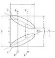
このため、図3に示すように、第1照射部18および第2照射部19は、被検面31(X−Y平面)に対して所定の俯角αで入射させるように設定されていることから、出射したレーザ光Lが被検面31上に形成する照射領域(T1、T2)が長尺な楕円形状となる。また、第1照射部18と第2照射部19とは、各々が出射したレーザ光LがYZ平面に対して対称であるように設定されていることから、第1照射部18が被検面31上に形成する第1照射領域T1と第2照射部19が被検面31上に形成する第2照射領域T2とがY軸方向に対して線対称となる。さらに、第1照射部18と第2照射部19とは、各々が出射したレーザ光LがY軸方向に対して所定の角度β(図3参照)で交差するように設定されていることから、第1照射領域T1の長軸方向とY軸方向とは角度βで交差しかつ第2照射領域T2の長軸とがとY軸方向とも角度βで交差することとなる。なお、被検面31に対する所定の俯角αは、その値が小さいほど楕円形状の照射領域を形成し易くなるものであり、この楕円の比率は感度と検査時間とを適宜勘案して設定され、0°よりも大きく90°以下のいずれの値であってもよい。ここで、所定の俯角αに90°が含まれるのは、楕円鏡等を用いて楕円形状の照射領域を形成することもできることによる。 For this reason, as shown in FIG. 3, the
このことから、照射手段12は、走査手段11の保持ステージ15に吸着保持されたウェハ30の被検面31に、Y軸方向のマイナス方向へ向けて互いの間隔が漸次的に増加する、すなわち最も小さい間隔dminから最も大きなdmaxまで漸次的に増加するV字状の位置関係となる第1照射領域T1と第2照射領域T2とを形成する。本実施例では、照射手段12は、第1照射領域T1と第2照射領域T2とが等しい面積で、かつ等しい強度分布となるように、設定されている。From this, the
この第1照射領域T1および第2照射領域T2は、絶対的な位置が固定された第1照射部18および第2照射部19により形成されていることから絶対的な位置が固定されているため、ウェハ30が走査手段11によりZ軸方向回りに回転されつつY軸方向に平行移動されることにより、第1照射部18および第2照射部19が被検面31上を相対的に螺旋状に移動するので、ウェハ30の被検面31を螺旋状に走査する(図2の矢印S参照)。換言すると、第1照射領域T1および第2照射領域T2は、滑らかな螺旋状の走行軌跡Sを辿って被検面31を走査する。 Since the first irradiation region T1 and the second irradiation region T2 are formed by the
ここで、第1照射部18から出射されたレーザ光Lは、第1照射領域T1で正反射されてY軸方向に対して角度βでかつ仰角α(出射角(90°−α))で、第1照射領域T1から出射することとなり、第2照射部19から出射されたレーザ光Lは、第2照射領域T2で正反射されてY軸方向に対して角度βでかつ仰角α(出射角(90°−α))で、第2照射領域T2から出射することとなる。この正反射以外の光すなわち散乱光Rを検出するために散乱光検出手段13が設けられている。 Here, the laser beam L emitted from the
散乱光検出手段13は、その光軸がY軸方向に対して略直交するように第1照射領域T1および第2照射領域T2に向かい、かつ光軸が被検面31(X−Y平面)に対して俯角γを為すように設定されており、第1照射領域T1および第2照射領域T2から出射した正反射光以外の光である散乱光Rを検出可能とされている。なお、本実施例では、正反射光以外の光である散乱光の検出方法の一例として散乱光検出手段13を示したが、当該散乱光の検出方法は、例えば楕円鏡を用いて集光することにより散乱光を検出するものであってもよく、本実施例に限定されるものではない。散乱光検出手段13は、制御機構14に電気的に接続されており、散乱光Rの検出結果を制御機構14に出力可能とされている。 The scattered light detection means 13 faces the first irradiation region T1 and the second irradiation region T2 so that the optical axis thereof is substantially orthogonal to the Y-axis direction, and the optical axis is the test surface 31 (XY plane). Is set so as to make a depression angle γ, and the scattered light R, which is light other than the specularly reflected light emitted from the first irradiation region T1 and the second irradiation region T2, can be detected. In the present embodiment, the scattered
この制御機構14は、走査手段11、照射手段12および散乱光検出手段13を統括的に駆動制御する。ここで、照射手段12から出射されたレーザ光Lにより形成される第1照射領域T1および第2照射領域T2からは、当該第1照射領域T1および第2照射領域T2(ウェハ30の被検面31)で吸収された分を除いた残りの光が正反射として出射され、原則的に、正反射光が出射する方向以外には光が出射することはない。これに対し、第1照射領域T1および第2照射領域T2に傷が存在する場合には、その傷を形成する微小な凹凸等によってレーザ光Lが乱反射するため、正反射光の他に乱反射による散乱光Rが生じる。同様に、第1照射領域T1および第2照射領域T2に異物が付着している場合には、その異物の凸壁等によってレーザ光Lが乱反射するため、正反射光の他に当該乱反射による散乱光Rが生じる。これらのことから、散乱光Rを散乱光検出手段13が検出することにより、被検面31の欠陥(上記した異物の付着、傷(結晶欠陥を含む)の存在等)の有無を検知することができる。 The
ここで、制御機構14では、上記した2つのエンコーダー(図示せず)により検出された保持ステージ15(ウェハ30)のY軸移動位置および回転角度位置が入力されていることから、特定の時刻における、Z軸回りに回転されつつY軸方向に平行移動するウェハ30の被検面31上で第1照射領域T1および第2照射領域T2が形成されている位置をY軸移動位置および回転角度位置に基づいて正確に特定することができる。また、制御機構14では、散乱光検出手段13で検出された散乱光Rの波形形状および強度から散乱光Rの原因となる欠陥の形状および大きさを分析することができる。これにより、制御機構14は、散乱光検出手段13から検出信号を受けた時刻からウェハ30の被検面31における位置を特定しつつ、当該検出信号から散乱光Rの原因となる欠陥が被検面31に生じた傷であるのか、被検面31に付着した異物であるのかを分析するとともに、散乱光Rの強度に基づいて当該傷または異物の大きさを分析する。このことから、本実施例の表面検査装置10では、制御機構14が分析手段として機能している。 Here, in the
また、表面検査装置10では、図示は略すが、検出信号の受信結果が、ウェハ30の被検面31における位置を特定しつつ表示手段に表示されるまたは紙等の媒体に印刷される構成とされており、これらに基づいて被検面31上の欠陥を分析者が分析することができる。 In the
この欠陥の分析を行う際、本発明に係る表面検査方法(表面検査装置10)では、ウェハ30の被検面31における位置を、従来の表面検査方法に比較してより狭い範囲に特定することができる。このことについて、以下で詳細に説明する。 When analyzing this defect, in the surface inspection method (surface inspection apparatus 10) according to the present invention, the position of the
前述したように、第1照射領域T1および第2照射領域T2は、ウェハ30の被検面31を螺旋状に走査する(図2の矢印S参照)こととなる、換言すると被検面31上には滑らかな螺旋状の走査線Sが形成されることとなる。ここで、図1および図2では、理解容易のために、V字状の位置関係とされた第1照射領域T1および第2照射領域T2の大きさ寸法がウェハ30の大きさに対して比較的大きく記載されているが、実際には、ウェハ30の被検面31に比較すると第1照射領域T1および第2照射領域T2は大変微少なものであることから、第1照射領域T1および第2照射領域T2の間では、図3に示すように、略X軸方向に沿う走査線(矢印Paおよび矢印Pb参照)が形成されるものとみなすことができる。換言すると、ウェハ30の被検面31上の欠陥は、相対的に第1照射領域T1および第2照射領域T2をX軸方向に沿って横切る(矢印Paおよび矢印Pb参照)ものとみなすことができる。このことから、Y軸方向に対して線対称とされた第1照射領域T1と第2照射領域T2とは、同一の走査線上で互いの間隔を漸次的に異ならせつつ対向し、かつY軸方向で見て等しい寸法の走査幅rを有している。 As described above, the first irradiation region T1 and the second irradiation region T2 scan the
ウェハ30の被検面31上の欠陥は、第1照射領域T1と第2照射領域T2とにより時間差を持って2度走査される、すなわち第1照射領域T1を横切った後、第2照射領域T2を横切ることから、第1照射領域T1を横切った際に第1照射領域T1から散乱光R1を出射させ、その後、第2照射領域T2を横切った際に第2照射領域T2から散乱光R2を出射させる。ここで、第1照射領域T1と第2照射領域T2とは、Y軸方向で見た位置に応じて互いの間隔が異なるV字状(最も小さい間隔dminから最も大きなdmaxまで漸次的に増加する)の位置関係とされていることから、散乱光R1が出射されてから散乱光R2が出射されるまでの時間がY軸方向で見た位置に応じて異なることとなる。この具体的な例として、ウェハ30の被検面31上に、Y軸方向で見て(被検面31の半径方向で見て)異なる位置に、等しい大きさ寸法の異物Waおよび異物Wbが付着しているものとする。The defect on the
異物Waの存在により散乱光検出手段13に検出された検出結果を図4(a)のグラフに示し、異物Wbの存在により散乱光検出手段13に検出された検出結果を図4(b)のグラフに示す。図4のグラフにおいて、Ra1は異物Waによる第1照射領域T1(図3参照)からの散乱光を示し、Ra2は異物Waによる第2照射領域T2(図3参照)からの散乱光を示し、Rb1は異物Wbによる第1照射領域T1(図3参照)からの散乱光を示し、Rb2は異物Wbによる第2照射領域T2(図3参照)からの散乱光を示す。また、散乱光Ra1が検出された時刻をta1とし、散乱光Ra2が検出された時刻をta2とし、散乱光Rb1が検出された時刻をtb1とし、散乱光Rb2が検出された時刻をtb2とする。 The detection result detected by the scattered light detection means 13 due to the presence of the foreign matter Wa is shown in the graph of FIG. 4A, and the detection result detected by the scattered light detection means 13 due to the presence of the foreign matter Wb is shown in FIG. Shown in the graph. In the graph of FIG. 4, Ra1 indicates scattered light from the first irradiation region T1 (see FIG. 3) due to the foreign matter Wa, Ra2 indicates scattered light from the second irradiation region T2 (see FIG. 3) due to the foreign matter Wa, Rb1 represents scattered light from the first irradiation region T1 (see FIG. 3) due to the foreign matter Wb, and Rb2 represents scattered light from the second irradiation region T2 (see FIG. 3) due to the foreign matter Wb. Further, the time when the scattered light Ra1 is detected is ta1, the time when the scattered light Ra2 is detected is ta2, the time when the scattered light Rb1 is detected is tb1, and the time when the scattered light Rb2 is detected is tb2. .
異物Waが第1照射領域T1を横切った後、第2照射領域T2を横切る場合の通り道をPa(図3参照)とすると、通り道Pa上で見て、第1照射領域T1の長軸に交差する個所から第2照射領域T2の長軸に交差する個所までの間隔d1が、検出結果では時刻をta1と時刻ta2との時間差(図4(a)参照)として反映される。また、異物Wbが第1照射領域T1を横切った後、第2照射領域T2を横切る場合の通り道をPb(図3参照)とすると、通り道Pb上で見て、第1照射領域T1の長軸に交差する個所から第2照射領域T2の長軸に交差する個所までの間隔d2が、検出結果では時刻をtb1と時刻tb2との差(図4(b)参照)として反映される。 When the path when the foreign object Wa crosses the first irradiation area T1 and then crosses the second irradiation area T2 is defined as Pa (see FIG. 3), it crosses the major axis of the first irradiation area T1 when viewed on the path Pa. In the detection result, the interval d1 from the position where the second irradiation region T2 intersects the long axis is reflected as the time difference between the time ta1 and the time ta2 (see FIG. 4A). Further, when the foreign material Wb crosses the first irradiation region T1, and then the path when crossing the second irradiation region T2 is Pb (see FIG. 3), the long axis of the first irradiation region T1 is viewed on the road Pb. In the detection result, the interval d2 from the location intersecting with the long axis of the second irradiation region T2 is reflected as the difference between the time tb1 and the time tb2 (see FIG. 4B).
このように、ウェハ30の被検面31上の異物は、必ず第1照射領域T1を横切った後、第2照射領域T2を横切り、かつ第1照射領域T1からの散乱光R1が生じた時刻t1と第2照射領域T2からの散乱光R2が生じた時刻t2との時間差が走査幅r内におけるY軸方向で見た位置に応じて異なることから、当該時間差から同一の走査線S上におけるY軸方向で見た位置、換言すると走査幅r内におけるY軸方向で見た座標位置を特定することができる。 As described above, the foreign matter on the
また、時刻をt1と時刻t2との中間の時刻をt0とし、当該中間時刻t0において第1照射領域T1および第2照射領域T2の中間に位置する個所、すなわち中間時刻t0において被検面31におけるY軸に重なる個所から、ウェハ30の被検面31上の異物のX軸方向(走査方向)で見た位置を特定することができる。このように、中間時刻t0に基づいて異物のX軸方向の位置を特定するのは次のことによる。第1照射領域T1および第2照射領域T2がY軸方向に角度βで交差する構成とされていることから、時刻をt1(時刻t2であっても同様)に基づいて異物のX軸方向の位置を特定すると時刻t1において第1照射領域T1が形成されている範囲e内に存在することを示してはいるが、範囲e内での位置が特定できない。これに対し、第1照射領域T1および第2照射領域T2がY軸方向に対して線対称とされていることから、中間時刻t0に該当する個所は、第1照射領域T1および第2照射領域T2の対称線となるY軸上に位置することとなるので、中間時刻t0に該当する個所を特定すれば、X軸方向で見た座標位置を特定できることによる。 Further, the time between t1 and t2 is set to t0, and at the intermediate time t0, a position located between the first irradiation region T1 and the second irradiation region T2, that is, at the
さらに、散乱光R(散乱光R1および散乱光R2)の強度および波形形状から、欠陥の大きさ寸法(上記した例では異物Waおよび異物Wbの大きさ寸法)を特定することができる。これは、同一の強度分布とされた第1照射領域T1および第2照射領域T2からの散乱光Rの強度および波形形状は、当該領域内に存在する欠陥の大きさに応じて異なることによる。 Furthermore, from the intensity and waveform shape of the scattered light R (scattered light R1 and scattered light R2), the size of the defect (the size of the foreign material Wa and the foreign material Wb in the above example) can be specified. This is because the intensity and waveform shape of the scattered light R from the first irradiation region T1 and the second irradiation region T2 having the same intensity distribution differ depending on the size of the defect present in the region.
このように、本発明に係る表面検査方法では、散乱光検出手段13から検出信号を受けた時刻に基づいて、散乱光Rを生じさせた欠陥のウェハ30の被検面31における位置を、第1照射領域T1および第2照射領域T2が形成されていた領域内にあることを特定する(ここまでは従来の表面検査方法も同様)ことに加えて、第1照射領域T1からの散乱光R1が生じた時刻と第2照射領域T2からの散乱光R2が生じた時刻との時間差に基づいて走査幅r内におけるY軸方向で見た位置(Y座標位置)を特定することができる。このことから、検出した欠陥が、第1照射領域T1および第2照射領域T2よりも微少なものであっても、ウェハ30の被検面31の全範囲においていずれの位置(座標位置)に存在するのか、正確に検知(特定)することができる。 Thus, in the surface inspection method according to the present invention, based on the time when the detection signal is received from the scattered light detection means 13, the position of the defect that caused the scattered light R on the
また、当該欠陥のX軸方向で見た位置は、第1照射領域T1からの散乱光R1が生じた時刻t1と第2照射領域T2からの散乱光R2が生じた時刻t2との中間時刻t0に基づいて特定することができる。よって、本発明に係る表面検査方法では、ウェハ30の被検面31における欠陥の位置をより正確に、換言するとX−Y平面で見た座標位置として特定することができる。 The position of the defect viewed in the X-axis direction is an intermediate time t0 between time t1 when the scattered light R1 from the first irradiation region T1 occurs and time t2 when the scattered light R2 from the second irradiation region T2 is generated. Can be identified based on. Therefore, in the surface inspection method according to the present invention, the position of the defect on the
さらに、本発明に係る表面検査方法では、当該欠陥の大きさ寸法を、散乱光R(散乱光R1および散乱光R2)の強度および波形形状から特定することができることから、被検体(上記した例ではウェハ30)の被検面31を、より精度良く検査することができる、換言するとより緻密な検査を行うことができる。 Furthermore, in the surface inspection method according to the present invention, the size of the defect can be specified from the intensity and waveform shape of the scattered light R (scattered light R1 and scattered light R2). Then, the
上記した本発明に係る表面検査方法を実行する表面検査装置10では、被検面31の検査の精度を高めるために、図5に示すように、第1照射領域T1および第2照射領域T2に対する走査速度が、n周目の走査におけるY軸方向の走査範囲を走査幅rnとすると、当該走査幅rnの下半分がn−1周目の走査における走査幅rn-1と重複し、かつ当該走査幅rnの上半分がn+1周目の走査における走査幅rn+1と重複するように設定されている。換言すると、n−1周目に第1照射領域T1´および第2照射領域T2´が形成される個所に対して、n周目に第1照射領域T1および第2照射領域T2が形成される個所が、r/2(走査幅の半分)だけY軸方向にずれる(Y軸方向で見て走査幅が略50(%)重なる)こととなる。In the
この表面検査装置10による表面検査の工程を以下で説明する。 The surface inspection process by the
図1および図2に示すように、被検体としての略真円のウェハ30を、走査手段11の保持ステージ15に適切な状態で載置し、保持ステージ15により吸着固定させる。 As shown in FIGS. 1 and 2, a substantially
この状態において、照射手段12の第1照射部18と第2照射部19とにより、ウェハ30の被検面31の中心に第1照射領域T1および第2照射領域T2を形成しつつ、走査手段11の回転機構16が等角速度で保持ステージ15を矢印A2方向に回転させつつ、リニア移動機構17が回転機構16を矢印A1方向に等速変位させる。 In this state, the
これにより、ウェハ30の被検面31に形成された第1照射領域T1および第2照射領域T2は、被検面31上を相対的に螺旋状に移動する(図2の矢印S参照)こととなり、照射手段12の第1照射部18と第2照射部19から出射されたレーザ光Lで螺旋状に走査することができる。このとき、第1照射領域T1および第2照射領域T2の大きさ寸法に対する走査手段11による移動速度が、n−1周目に第1照射領域T1´および第2照射領域T2´が形成される個所に対して、n周目に第1照射領域T1および第2照射領域T2が形成される個所が、r/2(走査幅の半分)だけY軸方向にずれる(Y軸方向で見て走査幅が略50(%)重なる)ように設定されている(換言すると走査ピッチがr/2)ことから、一度の走査工程において略真円な被検面31を確実に網羅することができる。なお、一度の走査工程において略真円な被検面31を確実に網羅する観点から、n−1周目に第1照射領域T1´および第2照射領域T2´が形成される個所に対する、n周目に第1照射領域T1および第2照射領域T2が形成される個所が隣接するように、第1照射領域T1および第2照射領域T2の大きさ寸法に対する走査手段11による移動速度が設定されていれば走査ピッチがr/2以外であってもよく、上記したものに限定されるものではない。 Thereby, the first irradiation region T1 and the second irradiation region T2 formed on the
ここで、ウェハ30の被検面31に異物Wcおよび異物Wd(図6参照)が付着しているものとする。図6に示すように、異物Wcは、n−1周目およびn周目に第1照射領域T1および第2照射領域T2を横切る通り道Pcを辿るものとし、異物Wdは、n−1周目、n周目およびn+1周目に第1照射領域T1および第2照射領域T2を横切る通り道Pdを辿るものとする。この異物Wcの存在により散乱光検出手段13に検出された検出結果を図7のグラフに示し、異物Wdの存在により散乱光検出手段13に検出された検出結果を図8のグラフに示す。 Here, it is assumed that the foreign matter Wc and the foreign matter Wd (see FIG. 6) are attached to the
図7のグラフにおいて、(a)はn周目に第1照射領域T1および第2照射領域T2を横切った際の検出結果を示しており、Rc1は異物Wcによる第1照射領域T1からの散乱光を示し、この時刻をtc1とし、Rc2は異物Wcによる第2照射領域T2からの散乱光を示し、この時刻をtc2としている。(b)はn−1周目に第1照射領域T1´および第2照射領域T2´を横切った際の検出結果を示しており、Rc1´は異物Wcによる第1照射領域T1からの散乱光を示し、この時刻をtc1´とし、Rc2´は異物Wcによる第2照射領域T2からの散乱光を示し、この時刻をtc2´としている。 In the graph of FIG. 7, (a) shows a detection result when the first irradiation region T1 and the second irradiation region T2 are crossed in the nth cycle, and Rc1 is scattered from the first irradiation region T1 by the foreign matter Wc. This time is indicated as tc1, and Rc2 indicates scattered light from the second irradiation region T2 due to the foreign matter Wc. This time is indicated as tc2. (B) has shown the detection result at the time of crossing 1st irradiation area | region T1 'and 2nd irradiation area | region T2' in the n-1 round, Rc1 'is the scattered light from 1st irradiation area | region T1 by the foreign material Wc. This time is tc1 ′, Rc2 ′ is scattered light from the second irradiation region T2 by the foreign matter Wc, and this time is tc2 ′.
表面検査装置10では、n−1周目の走査において異物Wcにより出射された散乱光Rc1´および散乱光Rc2´を、散乱光検出手段13により図7(b)に示す検出結果として得ることができる。この検出結果における、時刻tc1´と時刻tc2´との時間差に基づいて異物WcのY座標を特定し、時刻tc1´と時刻tc2´と中間時刻tc0´に基づいて異物WcのX座標を特定し、散乱光Rc1´および散乱光Rc2´の強度および波形形状から異物Wcの大きさ寸法を特定する。 In the
また、異物Wcのn周目の走査において異物Wcにより出射された散乱光Rc1および散乱光Rc2の、散乱光検出手段13による検出結果(図7(a)参照)からも同様に異物WcのX−Y平面で見た座標位置および大きさ寸法を特定し、このn周目の走査における分析結果とn−1周目の走査における分析結果とを勘案して、異物Wcを分析する。なお、このn周目の分析結果とn−1周目の分析結果とを、均等な重みを持つ構成としてもよくいずれか一方に重みを持たせる(例えば、第1照射領域内での強度分布特性に起因する検査精度の高さに応じて重みを設定する)構成であっても良い。 Similarly, from the detection result (see FIG. 7A) of the scattered light Rc1 and the scattered light Rc2 emitted by the foreign material Wc in the n-th scan of the foreign material Wc, the X of the foreign material Wc is similarly detected. The coordinate position and size dimension viewed in the −Y plane are specified, and the foreign matter Wc is analyzed in consideration of the analysis result in the n-th scan and the analysis result in the (n−1) -th scan. The analysis result of the nth cycle and the analysis result of the (n-1) th cycle may be configured to have equal weights, and one of them is given a weight (for example, intensity distribution in the first irradiation region). The weight may be set according to the high inspection accuracy caused by the characteristics).
このように、表面検査装置10では、異物Wcを、n周目に出射された散乱光Rc1および散乱光Rc2と、n−1周目に出射された散乱光Rc1´および散乱光Rc2´とに基づく検出結果を複合して分析するので、より正確な分析結果を得ることができる。 As described above, in the
同様に、Wdの場合には、以下のようになる。 Similarly, in the case of Wd, it is as follows.
図8のグラフにおいて、(a)はn周目に第1照射領域T1および第2照射領域T2を横切った際の検出結果を示しており、Rd1は異物Wdによる第1照射領域T1からの散乱光を示し、この時刻をtd1とし、Rd2は異物Wdによる第2照射領域T2からの散乱光を示し、この時刻をtd2としている。(b)はn−1周目に第1照射領域T1´および第2照射領域T2´を横切った際の検出結果を示しており、Rd1´は異物Wdによる第1照射領域T1からの散乱光を示し、この時刻をtd1´とし、Rd2´は異物Wdによる第2照射領域T2からの散乱光を示し、この時刻をtd2´としている。(c)はn+1周目に第1照射領域T1´´および第2照射領域T2´´を横切った際の検出結果を示しており、Rd1´´は異物Wdによる第1照射領域T1からの散乱光を示し、この時刻をtd1´´とし、Rd2´´は異物Wdによる第2照射領域T2からの散乱光を示し、この時刻をtd2´´としている。 In the graph of FIG. 8, (a) shows a detection result when the first irradiation region T1 and the second irradiation region T2 are crossed in the nth cycle, and Rd1 is scattering from the first irradiation region T1 by the foreign matter Wd. This time is indicated as td1, and Rd2 indicates scattered light from the second irradiation region T2 due to the foreign matter Wd. This time is indicated as td2. (B) has shown the detection result at the time of crossing 1st irradiation area | region T1 'and 2nd irradiation area | region T2' in the n-1 round, Rd1 'is the scattered light from 1st irradiation area | region T1 by the foreign material Wd. This time is td1 ′, Rd2 ′ is the scattered light from the second irradiation region T2 by the foreign matter Wd, and this time is td2 ′. (C) shows the detection result when crossing the first irradiation region T1 ″ and the second irradiation region T2 ″ in the (n + 1) th round, and Rd1 ″ is scattered from the first irradiation region T1 by the foreign matter Wd. This time is indicated as td1 ″, Rd2 ″ indicates scattered light from the second irradiation region T2 due to the foreign matter Wd, and this time is indicated as td2 ″.
表面検査装置10では、n−1周目の走査において異物Wdにより出射された散乱光Rd1´および散乱光Rd2´を、散乱光検出手段13により図8(b)に示す検出結果として得ることができる。この検出結果における、時刻td1´と時刻td2´との時間差に基づいて異物WdのY座標を特定し、時刻td1´と時刻td2´と中間時刻td0´に基づいて異物WdのX座標を特定し、散乱光Rd1´および散乱光Rd2´の強度および波形形状から異物Wdの大きさ寸法を特定する。 In the
また、異物Wdのn周目の走査において異物Wdにより出射された散乱光Rd1および散乱光Rd2の、散乱光検出手段13による検出結果(図8(a)参照)からも同様に異物WdのX−Y平面で見た座標位置および大きさ寸法を特定する。 Similarly, from the detection result (see FIG. 8A) of the scattered light Rd1 and scattered light Rd2 emitted by the foreign material Wd in the n-th scan of the foreign material Wd, the X of the foreign material Wd -Specify the coordinate position and size as viewed in the Y plane.
さらに、異物Wdのn+1周目の走査において異物Wdにより出射された散乱光Rd1´´および散乱光Rd2´´の、散乱光検出手段13による検出結果(図8(c)参照)からも同様に異物WdのX−Y平面で見た座標位置および大きさ寸法を特定する。 Further, the scattered light Rd1 ″ and the scattered light Rd2 ″ emitted by the foreign material Wd in the scan of the n + 1th round of the foreign material Wd are similarly detected from the detection result (see FIG. 8C) of the scattered light detection means 13. The coordinate position and size of the foreign object Wd viewed on the XY plane are specified.
これら、n−1周目の走査における分析結果と、n周目の走査における分析結果と、n+1周目の走査における分析結果とを勘案して、異物Wdを分析する。 The foreign matter Wd is analyzed in consideration of the analysis result in the (n−1) th scan, the analysis result in the (n + 1) th scan, and the analysis result in the (n + 1) th scan.
このように、表面検査装置10では、異物Wdを、n−1周目に出射された散乱光Rd1´および散乱光Rd2´と、n周目に出射された散乱光Rd1および散乱光Rd2と、n+1周目に出射された散乱光Rd1´´および散乱光Rd2´´とに基づく検出結果を複合して分析するので、より正確な分析結果を得ることができる。 Thus, in the
上記したように、本発明に係る表面検査方法(表面検査装置10)では、同一の走査線上(上記した実施例では螺旋状に走査されることから、Y軸方向で見て同一周回における走査線S上)に位置する第1照射領域T1と第2照射領域T2とが、Y軸方向(走査幅方向)に沿う位置に応じて間隔が異なるように設定されていることから、欠陥が存在する場合、当該欠陥が同一の走査線上で第1照射領域T1と第2照射領域T2とで走査されることにより、第1照射領域T1からの散乱光Rを検出する時刻と第2照射領域T2からの散乱光Rを検出する時刻とには異なる間隔に応じて時間差が生じるため、単一の照射領域内においてY軸方向(走査幅方向)で見た当該散乱光Rが出射された位置を特定することで、被検面31における欠陥の位置を正確に検知することができる。このように、照射領域(第1照射領域T1および第2照射領域T2)を小さくすることなく、欠陥の位置を正確に(X−Y平面で見た座標位置として)検知することができるので、一つのウェハ30(被検体)の被検面31を検査するのに要する時間が増加することを防止しつつ被検面31の全範囲における欠陥の位置を正確に検知することができる。 As described above, in the surface inspection method (surface inspection apparatus 10) according to the present invention, since scanning is performed in a spiral manner in the above-described embodiment, scanning lines in the same lap when viewed in the Y-axis direction are used. Since the first irradiation region T1 and the second irradiation region T2 located on (S) are set to have different intervals according to the position along the Y-axis direction (scanning width direction), there is a defect. In this case, the defect is scanned by the first irradiation region T1 and the second irradiation region T2 on the same scanning line, so that the time when the scattered light R from the first irradiation region T1 is detected and the second irradiation region T2 are detected. Since a time difference is generated according to a different interval from the time when the scattered light R is detected, the position where the scattered light R viewed in the Y-axis direction (scanning width direction) is emitted within a single irradiation region is specified. By doing so, the position of the defect on the
また、本発明に係る表面検査方法(表面検査装置10)では、同一の欠陥に起因する第1照射領域T1からの散乱光Rと第2照射領域T2からの散乱光Rとを、出射される時刻以外を等しいものとすることができることから、異なる間隔に応じて生じる時間差を容易かつ適切に取得することができ、被検面31における欠陥の位置をより正確に検知することができる。 In the surface inspection method (surface inspection apparatus 10) according to the present invention, the scattered light R from the first irradiation region T1 and the scattered light R from the second irradiation region T2 due to the same defect are emitted. Since the time other than the time can be made equal, the time difference generated according to the different intervals can be acquired easily and appropriately, and the position of the defect on the
さらに、本発明に係る表面検査方法(表面検査装置10)では、第1照射部18から出射されたレーザ光Lにより第1照射領域T1を形成し、かつ第2照射部19から出射されたレーザ光Lにより第2照射領域T2を形成していることから、容易に第1照射領域T1と第2照射領域T2との位置関係を適切なものとすることができる。また、第1照射領域T1と第2照射領域T2との位置関係の調節、および第1照射領域T1または第2照射領域T2における強度特性の調節を容易なものとすることができる。 Furthermore, in the surface inspection method (surface inspection apparatus 10) according to the present invention, the first irradiation region T1 is formed by the laser light L emitted from the
表面検査装置10では、回転機構16(回転手段)とリニア移動機構17(リニア移動手段)という簡単な組合せにより、走査軌跡Sを滑らかな螺旋状とすることができる。また、n−1周目に第1照射領域T1´および第2照射領域T2´が形成される個所に対する、n周目に第1照射領域T1および第2照射領域T2が形成される個所が隣接するように、第1照射領域T1および第2照射領域T2の大きさ寸法に対する走査手段11による移動速度が設定されていることから、一度の走査工程において略真円な被検面31を確実に網羅しつつ走査速度を増加することができる。このことから、信頼性および利便性が向上している。 In the
したがって、本発明の表面検査方法(表面検査装置10)によれば、一つの被検体(ウェハ30)の被検面31を検査することに要する時間の増大を招くことなく、被検面31における欠陥の位置を正確に検知することができる。 Therefore, according to the surface inspection method (surface inspection apparatus 10) of the present invention, the time required for inspecting the
なお、上記した実施例では、第1照射領域T1と第2照射領域T2とが、Y軸方向のマイナス方向へ向けて互いの間隔が漸次的に増加する(最も小さい間隔dminから最も大きなdmaxまで漸次的に増加する)V字状の位置関係とされていたが、第1照射領域T1からの散乱光R1と、第2照射領域T2からの散乱光R2との間隔がY軸方向(走査幅方向)で見て漸次的に異なるものであればよく、上記した実施例に限定されるものではない。例えば、図9に示すように、Y軸上で延在する第1照射領域T1exおよび第2照射領域T2と同様の第2照射領域T2exとして構成することができる。この場合、第1照射領域T1exから散乱光が出射された時刻と、第2照射領域T2exから散乱光が出射された時刻との時間差に基づいて欠陥のY軸方向の座標を特定することができ、第1照射領域T1exから散乱光が出射された時刻に基づいて欠陥のX軸方向の座標を特定することができる。また、上記したように、n−1周目に第1照射領域T1´および第2照射領域T2´が形成される個所に対して、n周目に第1照射領域T1および第2照射領域T2が形成される個所が、r/2(走査幅の半分)だけY軸方向にずれる(Y軸方向で見て走査幅が略50(%)重なる)構成である場合、図10に示すように、第1照射領域T1ex´と第2照射領域T2ex´とがX字状に交差する構成とすることができる。この場合、第1照射領域T1ex´と第2照射領域T2ex´との間隔の等しい個所が、図10を正面視した上半分と下半分とに形成されることとなるので、n周目の分析結果とn−1周目の分析結果とから、当該欠陥が上半分に存在したのか下半分に存在したのかを特定する必要がある。当該欠陥が上半分に存在したのか下半分に存在したのかの特定は、第1照射領域T1ex´と第2照射領域T2ex´との強度に差異を持たせ、当該差異に基づき判断する構成であってもよい。In the above-described embodiment, the distance between the first irradiation area T1 and the second irradiation area T2 gradually increases toward the minus direction in the Y-axis direction (from the smallest distance dmin to the largest dAlthough the positional relationship is V-shaped, which gradually increases tomax ), the distance between the scattered light R1 from the first irradiation region T1 and the scattered light R2 from the second irradiation region T2 is the Y-axis direction ( As long as it is gradually different as viewed in the scanning width direction), it is not limited to the above-described embodiment. For example, as shown in FIG. 9, it can be configured as a second irradiation region T2ex similar to the first irradiation region T1ex and the second irradiation region T2 extending on the Y axis. In this case, the coordinates of the defect in the Y-axis direction are specified based on the time difference between the time when the scattered light is emitted from the first irradiation region T1ex and the time when the scattered light is emitted from the second irradiation region T2ex. The coordinates of the defect in the X-axis direction can be specified based on the time when the scattered light is emitted from the first irradiation region T1ex . In addition, as described above, the first irradiation region T1 and the second irradiation region T2 are formed in the nth cycle with respect to the portion where the first irradiation region T1 ′ and the second irradiation region T2 ′ are formed in the n−1th cycle. 10 is a configuration in which the position where the is formed is shifted in the Y-axis direction by r / 2 (half of the scanning width) (the scanning width overlaps by approximately 50% when viewed in the Y-axis direction), as shown in FIG. The first irradiation region T1ex ′ and the second irradiation region T2ex ′ may be configured to intersect in an X shape. In this case, portions where the distance between the first irradiation region T1ex ′ and the second irradiation region T2ex ′ are equal are formed in the upper half and the lower half when the front view of FIG. It is necessary to specify whether the defect was present in the upper half or the lower half from the analysis result of No. 1 and the analysis result of the (n-1) th round. Whether the defect exists in the upper half or the lower half is determined based on the difference between the first irradiation region T1ex ′ and the second irradiation region T2ex ′. It may be.
また、上記した実施例では、第1照射部18から出射されたレーザ光Lにより第1照射領域T1を形成し、かつ第2照射部19から出射されたレーザ光Lにより第2照射領域T2を形成する構成であったが、同一の発生源から出射されたレーザ光を光学的に分割して第1照射領域と第2照射領域と形成するものであってもよい。この場合、第1照射領域と第2照射領域とをより等しい特性および形状とすることができる。 In the above-described embodiment, the first irradiation region T1 is formed by the laser light L emitted from the
さらに、上記した実施例では、走査手段11が回転機構16(回転手段)とリニア移動機構17(リニア移動手段)という簡単な組合せで構成され、被検面31上に滑らかな螺旋状の走査軌跡Sを形成するものであったが、被検面31上に直線状の走査軌跡を形成するものであってもよく、上記した実施例に限定されるものではない。 Further, in the above-described embodiment, the
上記した実施例では、走査手段11としての保持ステージ15にウェハ30を吸着保持させ、回転機構16およびリニア移動機構17により保持ステージ15を回転させつつY軸方向に移動させることにより、第1照射領域T1および第2照射領域T2で被検面31上を螺旋状に走査する構成であったが、第1照射領域T1および第2照射領域T2がその長尺方向と交差する方向で被検面31を走査するように、照射手段11およびウェハ30のうち少なくとも一方を相対的に変位させればよく、上記した実施例に限定されるものではない。 In the above-described embodiment, the
10 表面検査装置
11 走査手段
12 照射手段
13 散乱光検出手段
14 (分析手段としての)制御機構
16 (回転手段としての)回転機構
17 (リニア移動手段としての)リニア移動機構
18 (第1照射手段としての)第1照射部
19 (第2照射手段としての)第2照射部
30 (被検体としての)ウェハ
31 被検面
T1 第1照射領域
T2 第1照射領域
L (所定の光束としての)レーザ光
R 散乱光DESCRIPTION OF
Claims (7)
Translated fromJapanese前記照射領域として、同一の走査線上で対向しつつ走査方向に沿う互いの間隔が走査方向と略直交する走査幅方向で見て漸次的に異なるように設定された第1照射領域と第2照射領域とを用い、
前記第1照射領域からの散乱光と前記第2照射領域からの散乱光とを検出した時間差に基づいて、同一の走査線内における前記走査幅方向で見た散乱光の出射位置を検知することを特徴とする表面検査方法。A long irradiation region is formed on the test surface by causing a predetermined light beam to enter the test surface of the subject to be surface-inspected at a predetermined angle of incidence, and the irradiation region is a long one. By relatively displacing at least one of the luminous flux and the subject so as to scan the subject surface in a direction crossing the direction, and detecting scattered light emitted from the irradiation region, A surface inspection method for performing inspection,
As the irradiation region, the first irradiation region and the second irradiation, which are set so that the intervals along the scanning direction are gradually different when viewed in the scanning width direction substantially orthogonal to the scanning direction while facing each other on the same scanning line. Area and
Detecting an emission position of the scattered light viewed in the scanning width direction in the same scanning line based on a time difference between the scattered light from the first irradiation area and the scattered light from the second irradiation area. Surface inspection method characterized by.
前記照射手段は、前記照射領域として、同一の走査線上で対向しつつ走査方向に沿う互いの間隔が走査方向と略直交する走査幅方向で見て漸次的に異なるように設定された第1照射領域と第2照射領域とを形成し、
前記分析手段は、前記第1照射領域からの散乱光と前記第2照射領域からの散乱光とが検出された時間差に基づいて、同一の走査線内における前記走査幅方向で見た散乱光の出射位置を検知することを特徴とする表面検査装置。An irradiation means for forming a long irradiation region on the test surface by causing a predetermined light beam to enter the test surface of the subject to be surface-inspected at a predetermined incident angle, and the irradiation region includes Scanning means for relatively displacing at least one of the irradiation means and the subject so as to scan the test surface in a direction crossing the longitudinal direction, and scattered light emitted from the irradiation area can be detected A surface inspection apparatus comprising scattered light detection means and analysis means for analyzing the state of the test surface based on a detection result from the scattered light detection means,
The irradiating means is a first irradiating unit set as the irradiating region so as to be gradually different from each other in the scanning width direction substantially perpendicular to the scanning direction while facing each other on the same scanning line and along the scanning direction. Forming a region and a second irradiation region;
The analyzing means is configured to detect the scattered light viewed in the scanning width direction within the same scanning line based on a time difference in which the scattered light from the first irradiation region and the scattered light from the second irradiation region are detected. A surface inspection apparatus for detecting an emission position.
前記走査手段は、前記被検面の中心を通りかつ該被検面に直交する回転軸線回りに前記被検体を回転させる回転手段と、前記走査幅方向に前記被検体を直線移動させるリニア移動手段とを有し、前記照射領域に螺旋状の軌跡で前記被検面を走査させることを特徴とする請求項4ないし請求項6のいずれか1項に記載の表面検査装置。
The test surface is a substantially perfect circle,
The scanning means includes a rotating means for rotating the subject around a rotation axis passing through the center of the subject surface and orthogonal to the subject surface, and a linear moving means for linearly moving the subject in the scanning width direction. The surface inspection apparatus according to claim 4, wherein the surface to be scanned is scanned in a spiral locus in the irradiation area.
Priority Applications (1)
| Application Number | Priority Date | Filing Date | Title |
|---|---|---|---|
| JP2007027577AJP2008191066A (en) | 2007-02-07 | 2007-02-07 | Surface inspection method and surface inspection apparatus |
Applications Claiming Priority (1)
| Application Number | Priority Date | Filing Date | Title |
|---|---|---|---|
| JP2007027577AJP2008191066A (en) | 2007-02-07 | 2007-02-07 | Surface inspection method and surface inspection apparatus |
Publications (1)
| Publication Number | Publication Date |
|---|---|
| JP2008191066Atrue JP2008191066A (en) | 2008-08-21 |
Family
ID=39751291
Family Applications (1)
| Application Number | Title | Priority Date | Filing Date |
|---|---|---|---|
| JP2007027577APendingJP2008191066A (en) | 2007-02-07 | 2007-02-07 | Surface inspection method and surface inspection apparatus |
Country Status (1)
| Country | Link |
|---|---|
| JP (1) | JP2008191066A (en) |
Cited By (3)
| Publication number | Priority date | Publication date | Assignee | Title |
|---|---|---|---|---|
| JP2015075339A (en)* | 2013-10-06 | 2015-04-20 | 株式会社山梨技術工房 | Surface state inspection method for flat substrate and flat surface state inspection apparatus using the same |
| JP2018163175A (en)* | 2012-11-20 | 2018-10-18 | ケーエルエー−テンカー コーポレイション | Inspection beam shaping for improved detection sensitivity |
| WO2025057769A1 (en)* | 2023-09-14 | 2025-03-20 | 学校法人関西学院 | Method for evaluating substrate and device for evaluating substrate |
Citations (8)
| Publication number | Priority date | Publication date | Assignee | Title |
|---|---|---|---|---|
| JPS6275336A (en)* | 1985-09-30 | 1987-04-07 | Hitachi Electronics Eng Co Ltd | Foreign object inspection device |
| JPH05209841A (en)* | 1992-01-13 | 1993-08-20 | Hitachi Ltd | Method and apparatus for detecting foreign matter |
| JPH05312712A (en)* | 1992-05-11 | 1993-11-22 | Mitsubishi Electric Corp | Fine particle measuring method and fine particle measuring apparatus |
| JPH0611453A (en)* | 1993-05-17 | 1994-01-21 | Hitachi Ltd | Foreign object detection device |
| JPH09145631A (en)* | 1995-11-29 | 1997-06-06 | Nikon Corp | Surface foreign matter inspection device |
| JP2002513461A (en)* | 1996-06-04 | 2002-05-08 | ケーエルエー―テンカー コーポレイション | Optical scanning system for surface inspection |
| JP2002544477A (en)* | 1999-05-11 | 2002-12-24 | アプライド マテリアルズ インコーポレイテッド | Inspection system that performs two-dimensional imaging with a line light spot |
| JP2006017743A (en)* | 2005-09-12 | 2006-01-19 | Topcon Corp | Surface inspection device |
- 2007
- 2007-02-07JPJP2007027577Apatent/JP2008191066A/enactivePending
Patent Citations (8)
| Publication number | Priority date | Publication date | Assignee | Title |
|---|---|---|---|---|
| JPS6275336A (en)* | 1985-09-30 | 1987-04-07 | Hitachi Electronics Eng Co Ltd | Foreign object inspection device |
| JPH05209841A (en)* | 1992-01-13 | 1993-08-20 | Hitachi Ltd | Method and apparatus for detecting foreign matter |
| JPH05312712A (en)* | 1992-05-11 | 1993-11-22 | Mitsubishi Electric Corp | Fine particle measuring method and fine particle measuring apparatus |
| JPH0611453A (en)* | 1993-05-17 | 1994-01-21 | Hitachi Ltd | Foreign object detection device |
| JPH09145631A (en)* | 1995-11-29 | 1997-06-06 | Nikon Corp | Surface foreign matter inspection device |
| JP2002513461A (en)* | 1996-06-04 | 2002-05-08 | ケーエルエー―テンカー コーポレイション | Optical scanning system for surface inspection |
| JP2002544477A (en)* | 1999-05-11 | 2002-12-24 | アプライド マテリアルズ インコーポレイテッド | Inspection system that performs two-dimensional imaging with a line light spot |
| JP2006017743A (en)* | 2005-09-12 | 2006-01-19 | Topcon Corp | Surface inspection device |
Cited By (3)
| Publication number | Priority date | Publication date | Assignee | Title |
|---|---|---|---|---|
| JP2018163175A (en)* | 2012-11-20 | 2018-10-18 | ケーエルエー−テンカー コーポレイション | Inspection beam shaping for improved detection sensitivity |
| JP2015075339A (en)* | 2013-10-06 | 2015-04-20 | 株式会社山梨技術工房 | Surface state inspection method for flat substrate and flat surface state inspection apparatus using the same |
| WO2025057769A1 (en)* | 2023-09-14 | 2025-03-20 | 学校法人関西学院 | Method for evaluating substrate and device for evaluating substrate |
Similar Documents
| Publication | Publication Date | Title |
|---|---|---|
| CN100507550C (en) | Method of Ultrasonic Detecting Wing | |
| JP5622597B2 (en) | Ultrasonic flaw detection apparatus and ultrasonic flaw detection method | |
| EP3187861B1 (en) | Substrate inspection device and substrate inspection method | |
| US9080944B2 (en) | Method and apparatus for surface mapping using in-plane grazing incidence diffraction | |
| JP4641143B2 (en) | Surface inspection device | |
| JP6124024B2 (en) | Can body pinhole inspection system | |
| JP5090147B2 (en) | Defect inspection method, defect inspection apparatus, and line-shaped light source device used therefor | |
| JP2023123862A (en) | Method and device for ultrasonic inspection | |
| JP6192973B2 (en) | Ultrasonic inspection method and ultrasonic inspection apparatus | |
| JP2008286791A (en) | Surface defect inspection method and apparatus | |
| JP2008191066A (en) | Surface inspection method and surface inspection apparatus | |
| JP5332478B2 (en) | Laser scattering type defect inspection apparatus and laser scattering type defect inspection method | |
| JP2000298102A (en) | Surface inspection equipment | |
| US8547547B2 (en) | Optical surface defect inspection apparatus and optical surface defect inspection method | |
| EP3413037B1 (en) | Inspection device for sheet-like objects, and inspection method for sheet-like objects | |
| JP2008008689A (en) | Surface inspection apparatus and surface inspection method | |
| CN113030127A (en) | System and method for evaluating coating microstructure | |
| JP6875243B2 (en) | Plate-shaped inspection device | |
| CN113340924A (en) | Inspection system and control method of inspection system | |
| US12430742B2 (en) | Inspection system and inspection method | |
| JP2001242090A (en) | Surface inspection equipment | |
| CN110208272B (en) | Surface detection device and method | |
| US10739312B2 (en) | Ultrasonic inspection apparatus for a spherical body | |
| JPH09229909A (en) | Method and apparatus for inspecting moving subject | |
| JP2000314707A (en) | Surface inspection apparatus and method |
Legal Events
| Date | Code | Title | Description |
|---|---|---|---|
| A621 | Written request for application examination | Free format text:JAPANESE INTERMEDIATE CODE: A621 Effective date:20100120 | |
| A977 | Report on retrieval | Free format text:JAPANESE INTERMEDIATE CODE: A971007 Effective date:20111125 | |
| A02 | Decision of refusal | Free format text:JAPANESE INTERMEDIATE CODE: A02 Effective date:20120327 |