JP2008188439A - Medical recovery device - Google Patents
Medical recovery deviceDownload PDFInfo
- Publication number
- JP2008188439A JP2008188439AJP2008072303AJP2008072303AJP2008188439AJP 2008188439 AJP2008188439 AJP 2008188439AJP 2008072303 AJP2008072303 AJP 2008072303AJP 2008072303 AJP2008072303 AJP 2008072303AJP 2008188439 AJP2008188439 AJP 2008188439A
- Authority
- JP
- Japan
- Prior art keywords
- elastic gripping
- basket
- recovery device
- gripping member
- wire
- Prior art date
- Legal status (The legal status is an assumption and is not a legal conclusion. Google has not performed a legal analysis and makes no representation as to the accuracy of the status listed.)
- Granted
Links
Images


Classifications
- A—HUMAN NECESSITIES
- A61—MEDICAL OR VETERINARY SCIENCE; HYGIENE
- A61B—DIAGNOSIS; SURGERY; IDENTIFICATION
- A61B17/00—Surgical instruments, devices or methods
- A61B17/22—Implements for squeezing-off ulcers or the like on inner organs of the body; Implements for scraping-out cavities of body organs, e.g. bones; for invasive removal or destruction of calculus using mechanical vibrations; for removing obstructions in blood vessels, not otherwise provided for
- A61B17/221—Gripping devices in the form of loops or baskets for gripping calculi or similar types of obstructions
- A61B2017/2212—Gripping devices in the form of loops or baskets for gripping calculi or similar types of obstructions having a closed distal end, e.g. a loop
- A—HUMAN NECESSITIES
- A61—MEDICAL OR VETERINARY SCIENCE; HYGIENE
- A61B—DIAGNOSIS; SURGERY; IDENTIFICATION
- A61B17/00—Surgical instruments, devices or methods
- A61B17/22—Implements for squeezing-off ulcers or the like on inner organs of the body; Implements for scraping-out cavities of body organs, e.g. bones; for invasive removal or destruction of calculus using mechanical vibrations; for removing obstructions in blood vessels, not otherwise provided for
- A61B17/221—Gripping devices in the form of loops or baskets for gripping calculi or similar types of obstructions
- A61B2017/2215—Gripping devices in the form of loops or baskets for gripping calculi or similar types of obstructions having an open distal end
Landscapes
- Health & Medical Sciences (AREA)
- Surgery (AREA)
- Life Sciences & Earth Sciences (AREA)
- Molecular Biology (AREA)
- General Health & Medical Sciences (AREA)
- Vascular Medicine (AREA)
- Engineering & Computer Science (AREA)
- Biomedical Technology (AREA)
- Heart & Thoracic Surgery (AREA)
- Medical Informatics (AREA)
- Orthopedic Medicine & Surgery (AREA)
- Animal Behavior & Ethology (AREA)
- Nuclear Medicine, Radiotherapy & Molecular Imaging (AREA)
- Public Health (AREA)
- Veterinary Medicine (AREA)
- Surgical Instruments (AREA)
- Laser Surgery Devices (AREA)
- Sampling And Sample Adjustment (AREA)
- External Artificial Organs (AREA)
- Prostheses (AREA)
Abstract
Translated fromJapaneseDescription
Translated fromJapanese本発明は医療用装置に関する。更に詳細には、本発明は身体から結石などの目的物を捕捉および/または除去する医療用回収装置に関する。 The present invention relates to a medical device. More particularly, the present invention relates to a medical retrieval device that captures and / or removes objects such as stones from the body.
身体の種々の器官および通路は、石、結石などを発生することがある。胆石は米国では一般的な問題であり、胆石炎症の最も数多い原因である。胆管系の他の部分にある結石も一般的である。同様に、石、結石などは、腎臓または泌尿器系全体で、その尿管やその遠位側ばかりでなく、尿細管や大および小腎杯でも発生する可能性がある。腎杯は腎臓にある中空の採取構造であり、腎盂から延在し、小腎杯は特に腎錐体を結合する。単純にするため、腎杯は、腎単位の接続細管から尿管へと延在する管路と見なすことができる。 Various organs and passages of the body can generate stones, stones, and the like. Gallstones are a common problem in the United States and are the most common cause of gallstone inflammation. Stones in other parts of the bile duct system are also common. Similarly, stones, stones, etc. can occur throughout the kidney or urinary system, not only in its ureter and its distal side, but also in tubules and large and small kidney cups. The renal cup is a hollow collection structure in the kidney, extending from the renal pelvis, and the small renal cup specifically connects the renal cones. For simplicity, the renal cup can be viewed as a duct that extends from the connecting tubules of the renal unit to the ureter.
胆管および泌尿器系から石、結石などを除去すため、侵襲性が最小の外科的処置が開発されてきた。このような処置は、(例えば胆嚢摘出などの)侵襲的開放性外科的処置の実施を回避し、代わりに経皮的にアクセスすることができ、石、結石などを経皮的に挿入したアクセス用シースを通して除去する。石、結石などが見られる特定の系および系の特定の位置に応じて、幾つかのアクセス経路が適切である。しかし、特定のアクセス経路に関係なく、経皮的抽出は通常、鉗子またはバスケットの先端を有するカテーテルを使用して、石、結石などを噛み合わせて除去することに基づく。 Minimally invasive surgical procedures have been developed to remove stones, stones, etc. from the bile duct and urinary system. Such a procedure avoids performing invasive open surgical procedures (such as cholecystectomy, for example) and can be accessed percutaneously instead, with access through the percutaneous insertion of stones, stones, etc. Remove through sheath. Depending on the particular system where stones, stones, etc. are found and the particular location of the system, several access paths are appropriate. However, regardless of the particular access route, percutaneous extraction is usually based on the use of forceps or a catheter with a basket tip to bite away stones, stones, and the like.
閉じたワイヤの先端を有するバスケット(螺旋形または直線のワイヤ)により、石などをバスケットの側部から入れながら、開放した端のバスケットは石などに頭からアプローチすることができる。他の回収器および把持器には鉗子、または除去すべき本体を囲むループまたはスネアがあり、ループまたはスネアは円形または平坦なワイヤで作成する。平坦なワイヤは、円形のワイヤに対して、平坦なワイヤを組み込んだバスケットの方が、使用中の捻りに対する抵抗が優れているという利点を有する。更に、外科的技術が進歩し、比較的直径が小さい内視鏡用アクセサリ通路が開発される一方、石抽出バスケットに組み込まれる円形ワイヤの直径を削減する努力は、残念ながら同様の成功を収めていない。実際には、円形ワイヤの有効最小直径は(ステンレス鋼のワイヤでも)、約0.007から0.010インチ(約0.178から0.254mm)に留まっている。円形または平坦なワイヤを含むシースまたはカニューレの内側には無駄になる空間が大きいので、このようなワイヤの有効直径に対する制限のため、小さい直径の有用な螺旋形石抽出器、特に外径(つまりワイヤを含むシースまたはカニューレの直径)が約1.7フレンチ(0.022インチつまり0.56mm)未満の抽出器が開発できなかった。 A basket with a closed wire tip (spiral or straight wire) allows the open end basket to approach the stone or the like from the head while the stone or the like enters from the side of the basket. Other collectors and graspers have forceps, or loops or snares surrounding the body to be removed, where the loop or snare is made of a round or flat wire. A flat wire has the advantage over a round wire that a basket incorporating a flat wire has better resistance to twist during use. Furthermore, while surgical techniques have advanced and relatively small diameter endoscopic accessory passages have been developed, efforts to reduce the diameter of the round wire incorporated into the stone extraction basket have unfortunately been similarly successful. Absent. In practice, the effective minimum diameter of a round wire (even a stainless steel wire) remains about 0.007 to 0.010 inches (about 0.178 to 0.254 mm). Because there is a large amount of wasted space inside a sheath or cannula containing a round or flat wire, a small diameter useful helical stone extractor, especially the outer diameter (ie An extractor with a diameter of the sheath or cannula containing the wire (less than about 1.7 French (0.022 inches or 0.56 mm)) could not be developed.
より小さい回収装置の別の望ましい特徴、特に泌尿器用途に重要であるのは、より簡単に除去するため、石または結石を破壊するレーザ・ファイバまたは液圧砕石術ワイヤなどのアクセサリ器具を収容できる、尿管鏡などの直径が小さい内視鏡で作用する装置になることである。より小さい鏡に使用可能な空間および内腔の数は制限されているので、内腔の直径を大きくする必要なく、内視鏡の既存のアクセサリ通路を共有できる装置を作成すると有利である。直径の小さい回収装置には、尿路鏡を通して導入できるものがあるが、ワイヤのサイズおよび設計により、砕石術処置用などのアクセサリ器具を回収装置のワークピースに導入できる内腔を有することができない。 Another desirable feature of smaller retrieval devices, particularly important for urological applications, is that they can accommodate accessory instruments such as laser fibers or hydraulic lithotripsy wires that break stones or stones for easier removal. This is a device that works with an endoscope such as a ureteroscope having a small diameter. Because the number of spaces and lumens available for smaller mirrors is limited, it would be advantageous to create a device that can share the existing accessory passages of an endoscope without having to increase the diameter of the lumen. Some small diameter collection devices can be introduced through a urethroscope, but the wire size and design cannot have a lumen through which accessory instruments such as for lithotripsy procedures can be introduced into the collection device workpiece .
従って、本発明の目的は新規な医療用回収装置を提供することである。 Accordingly, an object of the present invention is to provide a novel medical recovery apparatus.
前記課題は、体内の種々の位置から石、結石、凝固物、異物などの目的物と噛合いまたは捕捉し、除去、抽出または回収するのに特に有用である本発明の医療用回収装置により解決される。本発明の医療用回収装置の開示された実施態様は、それぞれ、1本の細長い部材から形成され、細長い部材それぞれの遠位部分の弾性把持部材が、基本的に装置の長さだけ延在する材料の連続体を呈することを特徴とする。弾性部材はバスケットまたは鉗子を形成する。 The above problems are solved by the medical recovery device of the present invention which is particularly useful for engaging or capturing, removing, extracting or recovering objects such as stones, stones, coagulum, and foreign substances from various positions in the body. Is done. The disclosed embodiments of the medical retrieval device of the present invention are each formed from a single elongate member, with the elastic gripping member at the distal portion of each elongate member extending essentially the length of the device. It presents a continuum of materials. The elastic member forms a basket or forceps.
本発明の1つの実施態様では、個々の把持部材は、細長い部材の一端の周囲に縦方向にスロットを生成した結果として生じる。細長部材は中空のカニューレまたは中実部材でよく、円筒形であることが好ましい。スロットは、細長部材の材料を、縦方向の細長いスロットの形状で除去することによって形成される。弾性把持部材は、細長部材の周囲にその材料を残した結果として生じる。あるいは、部材は、材料を除去して、細長部材の壁の中に既に入れてあった強化ワイヤなどの要素を露出させた結果として生じる。部材は、把持部材を装置の遠端で相互接続すると、バスケットまたはスネアを、あるいは違う場合は把持用鉗子を含むことができる。 In one embodiment of the invention, the individual gripping members result from the creation of slots longitudinally around one end of the elongated member. The elongate member may be a hollow cannula or a solid member, and is preferably cylindrical. The slots are formed by removing the elongated member material in the form of longitudinal elongated slots. The elastic gripping member results from leaving the material around the elongated member. Alternatively, the member results from removing material to expose elements such as reinforcing wires that were already in the wall of the elongated member. The member can include a basket or snare when the gripping members are interconnected at the distal end of the device, or gripping forceps otherwise.
バスケット作成方法は、以前ははんだ付け、溶着、かしめ、またはバスケットのワイヤを別個の軸部片に取り付ける他の方法を含んでいた。ワイヤまたは弾性把持部材を装置の近位軸部分と連続させることにより、いかなる結合もなくなるので有利である。このような結合部は破損しやすく、場合によっては患者の体内に外れた破損ワイヤがあるという危険な状況になる。薄肉カニューレまたは管から作成した本発明の回収バスケット、把持器または鉗子の別の利点は、大きく開いた内腔と比較的小さい外径である。この大きく開いた内腔により、尿路鏡を通して回収装置を挿入する場合に、砕石術処置を実行できるので有利である。本発明は、ワイヤと軸との結合部が外径および/または利用可能な内腔径を大きくする既存の回収または抽出装置の外径より、装置の全体的外径をはるかに小さくできる点で、従来技術に比べて特に有利である。本発明の回収装置は、わずか1フレンチ(0.33mm)の外径にできるが、尿路鏡およびレーザ・ファイバまたは砕石術レーザ・ファイバと組み合わせて使用するには、2〜3フレンチ(0.67〜1mm)が好ましいサイズである。装置が小さくなると、体内のより深い位置に到達し、石および結石を捕捉して回収することができる。直径が小さくなると、患者の体内に装置を導入し、操作する間、患者が不快になる危険および組織を誤って損傷する危険が低下することも予想されることは言うまでもない。 Basket making methods previously included soldering, welding, caulking, or other methods of attaching basket wires to separate shaft pieces. Advantageously, continuation of the wire or elastic gripping member with the proximal shaft portion of the device eliminates any coupling. Such joints are prone to breakage, which can lead to a dangerous situation where there is a broken wire in the patient's body. Another advantage of the retrieval basket, grasper or forceps of the present invention made from a thin-walled cannula or tube is a wide open lumen and a relatively small outer diameter. This wide open lumen is advantageous because a lithotripsy procedure can be performed when the retrieval device is inserted through a urethroscope. The present invention has the advantage that the overall outer diameter of the device can be made much smaller than the outer diameter of existing collection or extraction devices where the wire-shaft joint increases the outer diameter and / or the available lumen diameter. This is particularly advantageous over the prior art. The recovery device of the present invention can have an outer diameter of only 1 French (0.33 mm), but for use in combination with a ureteroscope and laser or lithotripsy laser fiber, 2-3 French (0. 67-1 mm) is a preferred size. As the device becomes smaller, it can reach deeper positions in the body and capture and collect stones and stones. It goes without saying that smaller diameters are also expected to reduce the risk of patient discomfort and accidental tissue damage during introduction and operation of the device in the patient's body.
回収装置の使用時には、目標物を視覚化することが不可欠である。石または結石を回収する最小侵襲的処置の大部分に使用されている内視鏡は、通常、治療部位に付属装置を導入するため、第2または第3アクセサリ通路または内腔を有する。尿路鏡などの直径が比較的小さい内視鏡は、供給される回収装置が通る非常に狭いアクセサリ通路を有する。本発明の利点は、大きい中心内腔がある管状設計により、配置するのに使用できるガイドワイヤ、またはレーザ・ファイバまたは電気油圧式砕石術ワイヤなどの石または結石を破壊する装置など、処置に有用な追加的器具を導入することができる。バスケットのワイヤを装置の軸にはんだ付けしたり、バスケット・ワイヤを圧縮して細い直径にしたりするのに必要な従来のバスケットまたは把持鉗子製造技術では、狭い作業通路内に他の装置にとって十分な追加の余地が残らない。中心の内腔は器具を内部作業区域に導入するのに有用であるが、代替的実施態様では、カニューレの端部をはんだまたは別の材料で充填し、組織にそれほど外傷を与えないチップを形成する。 It is essential to visualize the target when using the recovery device. Endoscopes used in most minimally invasive procedures to retrieve stones or stones typically have a second or third accessory passage or lumen to introduce an accessory device at the treatment site. Endoscopes such as urethroscopes that have a relatively small diameter have a very narrow accessory passage through which a collection device is fed. The advantages of the present invention are useful for procedures such as guidewires that can be used for placement with tubular designs with large central lumens, or devices that break stones or stones such as laser fibers or electrohydraulic lithotripsy wires Additional equipment can be introduced. Conventional basket or grasping forceps manufacturing techniques required to solder the basket wire to the device shaft or compress the basket wire to a narrow diameter are sufficient for other devices within a narrow working path. There is no additional room left. Although the central lumen is useful for introducing the instrument into the internal working area, in an alternative embodiment, the end of the cannula is filled with solder or another material to form a tip that is less traumatic to the tissue. To do.
本発明の追加の利点は、構造が比較的単純なことである。金属カニューレまたは円筒で構成された装置は、カニューレ/円筒に一連の縦方向スロットを作成し、個々の弾性把持部材を形成することによって形成することができる。このプロセスの結果、完全に整列した把持部材が生じ、把持部材の改造を除いて、バスケットまたは把持鉗子の組立に通常必要な熟練の手作業の多くが省略される。弾性把持部材を可塑変形または熱硬化してバスケットまたは鉗子の外側に延在する形状にすると、曲げ応力が除去され、展開中に延長した装置が弛緩状態になるので遊離である。本発明の回収装置は、同軸外部シースまたは内視鏡などの外部限定機構を使用し、患者から除去するために目標物を捕捉し、保持する弾性把持部材を開閉することができる。代替方法は、装置の内腔に配置された軌道部材を含み、バスケットまたは把持鉗子を開閉することができる。 An additional advantage of the present invention is that the structure is relatively simple. Devices composed of metal cannulas or cylinders can be formed by creating a series of longitudinal slots in the cannula / cylinder and forming individual elastic gripping members. This process results in a perfectly aligned gripping member, omitting much of the skilled manual work normally required to assemble the basket or gripping forceps, except for modification of the gripping member. When the elastic gripping member is plastically deformed or thermoset into a shape that extends outside the basket or forceps, the bending stress is removed and the extended device is relaxed during deployment and is free. The retrieval device of the present invention can open and close an elastic gripping member that captures and holds a target for removal from a patient using an external limiting mechanism such as a coaxial outer sheath or endoscope. An alternative method includes a track member disposed in the lumen of the device and can open and close the basket or grasping forceps.
本発明の別の実施態様では、回収装置は、内部に入れた強化ワイヤを有するプラスチック管を備えた細長い部材から形成する。これらのワイヤは、それぞれが細長部材の長さに延在摺る材料の連続体であり、これを相互接続する管の遠位部分で露出し、回収バスケットまたは把持鉗子を作成する弾性把持部材を形成する。 In another embodiment of the present invention, the retrieval device is formed from an elongate member with a plastic tube having a reinforcing wire encased therein. Each of these wires is a continuous body of material that extends the length of the elongate member and is exposed at the distal portion of the tube that interconnects it to form an elastic gripping member that creates a retrieval basket or gripping forceps To do.
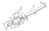
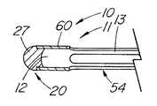
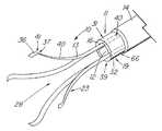
本発明の医療用回収装置10は、図1に示すように、遠位部分37および近位部分21を含む細長い部材11からなる。遠位部分は、目的物を捕捉して操作する作業空間を提供する作業空間体積28を提供するよう形成された複数の弾性把持部材13を含む。細長い円筒部材11は、1つの材料(または異なる材料)の2つ以上の識別可能な要素または接続された要素がはんだ付け、かしめ、または他の何らかの方法で結合されたのではなく、単一の連続要素であるステンレス鋼などの第1の材料40の連続体も含む。図1から図18に示す実施態様では、第1の材料の連続体は、1本のカニューレ60または中実の棒62を備え、そこからバスケット54、把持鉗子23またはスネア26などの医療用回収装置10を形成する。円形または他の円筒形のカニューレまたは棒を使用することが好ましいが、細長部材11は多角形断面を有してもよい。第1の材料40の連続体は、弾性把持部材を形成するのに適した弾性材料で構成することが好ましい。曲げ応力を保持することができ、予備形成した形状に弾力的に復帰できる任意の弾性材料を使用することができる。金属は、医療用回収装置10の作成にとって好ましい材料であり、最も好ましい材料はステンレス鋼、またはニチノール(NiTi)として市販されているニッケル・チタン合金などの超弾性特性を有する合金である。好ましいステンレス鋼は、300シリーズのいずれかであり、400シリーズも代替材料を提供する。十分な弾性率を有する特定のポリマー材料も、比較的大きいサイズの装置に使用することができる。ニチノールなどの超弾性材料は、耐破断性または耐屈曲性が改良されているので、肉厚が非常に薄い最小級の装置(4フレンチ(1.32mm)未満)に好ましい。 The
細長部材から弾性把持部材13を形成する好ましい方法は、弾性把持部材13間にスロット15、開放区域または空間を生成することにより、細長部材11の材料を除去することである。例示的実施態様では、細長い円筒形部材、特にカニューレ60の壁16を通してスロット15を確立することにより、カニューレ60から4本の弾性把持部材13を形成する。 A preferred method of forming the elastic gripping
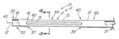
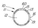
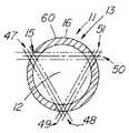
図2はカニューレ60の側面図を示し、弾性把持部材を改造する前の回収装置10の遠位部分37を示す。図4は、4−4線に沿った図3の装置の断面図である。スロット15は、所望の弾性把持部材と数が等しく、細長部材の壁16に組み込まれる。図示の実施態様のように中空の金属カニューレ60を使用する場合は、弾性把持部材13間の望ましくない材料を、標準的EDMワイヤ・マシンまたはレーザなどの切削手段で除去することができる。代替方法は噴射水、機械加工、または化学的エッチングを含む。ワイヤ・マシンを使用する場合は、連続的EDMワイヤのパイロット穴を細長部材11に穿孔する。切削ワイヤまたはレーザの直径がスロット15の直径を決定し、その結果、弾性把持部材13の幅、厚さおよび/または直径を決定する。カニューレにスロットを切削する代替方法は、棒を挿入して、レーザ(または同様の機能を有する他の切削器具)を設定し、挿入した棒によってカニューレ60の反対側まで延在しないようにした所定の深さの切断部を作成する。更に別の方法は、細長部材11の初期作成中にスロット、空間または開口を生成するものであって、プラスチックで作成した装置の場合は特にそうである。例示的実施態様では、スロット15は細長部材11の遠端20の前で終了し、近位部分21を備えてバスケット54の柄または軸を構成する閉じた近位側円筒19のような開放遠位側円筒55を残す。閉鎖遠位側円筒55は、弾性把持部材の遠端41を統合する手段を提供し、はんだ継手またはかしめ装置など、別個の接続部を不要とする。 FIG. 2 shows a side view of the
縦方向のスロット15を最初に形成した後、弾性把持部材13は、基本的に細長部材の縦軸43と平行である圧縮形状17を有する。カニューレ60の実施態様では、これで、元の内腔サイズおよび最大内腔サイズを有する細長部材11が生成され、図4に示すようにコンパクトまたは圧縮された形状17である間、回収装置10の全径は基本的に増加しない。図1に戻ると、バスケット54は、個々の弾性把持部材13を可塑変形させて外側に突き出す第2拡張形状18にし、したがって回収または操作のために結石を罠に入れることができ、外側に突き出す把持部材の間に、作業空間体積28を生成することによって形成する。把持部材には、図1の弓形、または図17の実施態様で示すように弾性把持部材13に導入曲げ部61を生成することによって生成された角張った形状など、目的物を捕捉する解法領域を生成する任意の形状を与えることができる。 After the
本発明の回収装置10をステンレス鋼ではなくニチノールで作成する場合は、スロット15を切削し、形状を保持するマンドレルまたは固定具を使用して、弾性把持部材13で細長い形状18を形成する。次に装置を熱硬化または「トレーニング」して拡大形状18にし、弾性把持部材の曲げ応力を除去する。例えば、完成装置を熱硬化する温度は500℃以上でよい。金属が展性のマルテンサイト状態から形状記憶のオーステナイト状態へと変化する変態温度は、弾性把持部材がその形状を維持し、回収装置として機能するのに十分な弾性を維持するよう、装置を使用する温度より低くなければならない。この温度は、室温、例えば10℃未満に設定するか、室温と体温との間に設定して、装置がマルテンサイト状態にある間に外部シースに容易に装填できるようにすることができる。ニチノールに曲げ部を形成する代替方法は、冷間加工として知られる方法で材料を可塑変形させることである。ニチノールに、局所的位相変化があるよう、機械的に過剰な応力を与えて、その部位に永久曲げが生じるようにする。 When the
回収バスケット54の開閉を実行するには、図1に示すように、同軸外部シースなどの外部拘束機構14を使用する。装置の全体的サイズを最小にすることが重要な場合は、当然、細長い円筒形部材11上で軸方向に移動できる最小のシース14を選択することが重要である。細長い円筒部材11と外部拘束機構11との間の摩擦を軽減するには、ポリテトラフルオロエチレン(PTFE)などの潤滑材料の薄い膜35を細長い円筒形部材11の外面に塗布すると有利である。 To execute opening and closing of the
図12は、結石24を捕捉した状態で閉位置30にある、図1の装置の側面図である。結石24または他の捕捉目的物がないと、ほぼ閉じた位置30は基本的に図2のコンパクトな位置と同じになる。外部拘束機構14が弾性把持部材13上に前進し、弾性把持部材13が拘束された作業空間体積28内に結石をしっかり固定するまで、近端39から弾性把持部材13を弾性変形させ、半径方向に圧迫する。所望に応じて、回収装置10および回収された目的物24は身体から一緒に除去することができる。 12 is a side view of the apparatus of FIG. 1 in the
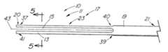
図3は、弾性把持部材13が圧縮形状17にある状態で1組の把持鉗子23を含む、図1の回収装置10の代替実施態様の側面図を示す。把持鉗子は基本的に図1の装置と同じように製造するが、ただスロット15が細長部材11の遠端20まで延在する。バスケットの製造と同様、患者の体内から目的物を受けるため、図7に示すように開位置まで弾性把持部材を可塑変形または熱硬化する。目的物の捕捉および保持を容易にするため、弾性把持部材の遠位チップ36は内側に曲げてもよい。弾性把持部材は、図1のバスケット54と同様の方法で前進する外部拘束機構14によって、目的物物上で閉じる。 FIG. 3 shows a side view of an alternative embodiment of the
図8は、図1の回収装置10の絵画的図を示し、尿路鏡44と組み合わせて使用する方法を示す。尿管内から結石を回収するには、通常、一連のレンズまたは光ファイバに接続して標的を視覚化できる光学レンズ45、照明のための光源53、および器具の導入および/または流体の通過のための少なくとも1本のアクセサリ通路46を含む標準的尿路鏡44を使用する。典型的な尿路鏡のアクセサリ通路46は、2.0フレンチ(0.67mm)から少なくとも6フレンチ(2mm)の範囲でよい。例示的実施態様は、約3フレンチ(1mm)の外径を有し、3.4フレンチ(1.12mm)のアクセサリ通路とともに使用することができる。圧縮したバスケット54または細長い円筒形部材11の外径は約2フレンチ(0.67mm)であり、通路12は直径約.066mmである。通路12は、クラッディングを除いて直径約200ミクロンの標準的なレーザ砕石術ワイヤを収容することができる。レーザは結石24にエネルギーを送り、尿管を通過したり、装置の通路12を通って回収できたりするこれより小さい破片へと破壊する。小さいサイズの回収装置10を使用すると、内視鏡を通過できて有利であるが、9フレンチ(3mm)以上など、本発明の比較的大きいバスケットまたは鉗子の実施態様も、体内の一般的回収用途に、特に大きい中心内腔が望ましい場合に使用できることが想定される。 FIG. 8 shows a pictorial view of the
カニューレから回収装置10を形成するさらなる利点は、弾性把持部材が(図4および図6に示すように)半円形の断面形状になることである。弾性把持部材が半円形で、同一サイズおよび材料の平坦または棒形の部材であると、個々の半円形の弾性把持部材は、目的物物に対して約25倍の内方向の力を加えることができることが、経験的に示されている。実証されたこの構造的利点は、非常に優れた強度のために建物構造の梁設計に使用されているI形鋼の場合と同様である。 A further advantage of forming the
カニューレから作成する以外に、本発明のバスケットおよび把持鉗子は、中実の細長い部材から作成することができる。図5は、中実部材から形成し、楔形の弾性把持部材を有する、図3の代替実施態様の5−5線に沿って切断した細長い円筒形部材11の断面図を示す。図示された楔形の把持部材は、金属カニューレから作成した実施態様と基本的に同じ方法で、細長い部材に2本のスロットを作成して形成することができる。楔形把持部材から作成したバスケットおよび把持器は、標準的な円形または平坦なワイヤであり、米国特許出願第60/078,290号号明細書に記載されたものより小さい直径に圧縮されるので有利である。 In addition to being made from a cannula, the basket and grasping forceps of the present invention can be made from a solid elongate member. FIG. 5 shows a cross-sectional view of the elongated
図6は、装置を中実部材62から形成し、弾性把持部材13が基本的に半円形である、図3の代替実施態様の近位方向で見た断面図を示す。これは、中実の細長い部材の遠端20に、少なくとも弾性把持部材の近端になる箇所付近の点まで中心ボア22を作成することにより形成する。次に、スロット15を形成して圧縮形状17の把持鉗子を精製し、これを図7の実施態様と同じ方法で拡大形状18に形成する。図6の実施態様の半円形把持部材は、カニューレから形成した場合と全体の形状が同じであるが、中心ボアは通常、ほぼ弾性把持部材の近端まで、またはそれを越えて延在する。概して、中実の円筒形原料から作成した把持器およびバスケットは、中実の軸または近位部分21を有して中心内腔がなく、したがって追加の器具または装置を収容することができない。 FIG. 6 shows a cross-sectional view, viewed in the proximal direction, of the alternative embodiment of FIG. 3 in which the device is formed from a
図1から図8に示す実施態様は、4本の弾性把持部材を有する回収装置を開示するが、2本から8本の把持部材を有する装置が可能である。図9は、1本のスロットを切削することによって2本の弾性把持部材13を有する、図1の回収装置10の代替実施態様の絵画的図を示す。このタイプの回収装置は、カテーテル、ペースメーカーのリードなど、細長い異物52を回収するスネア26として、特に有用になり得る。 Although the embodiment shown in FIGS. 1-8 discloses a collection device having four elastic gripping members, devices having two to eight gripping members are possible. FIG. 9 shows a pictorial view of an alternative embodiment of the
図13は、3本のスロット15によって形成された3本の弾性把持部材13を有する、図1の装置の拡張していない代替実施態様の断面図を示す。この特定の実施態様では、3本のスロット47と48、49と50、51を形成する通路は、断面に架空の三角形を精製する。本明細書では、「スロット」とは、カニューレの壁を通る1本の縦方向の開口を指し、「通路」はカニューレの2本の異なるスロットを通る想像線を指し、いかにスロットが形成されるかを示す。したがって、1本のスロットは2つの異なる要素番号(例えば48、49および50、51)を有することがある。第1スロット47は、その結果生じる出口スロット48が、偶数の把持部材を有する装置のように直径の反対側ではなく、第1入口スロット47に対して円筒形の円周に沿って120°にあるよう、細長い円筒形部材に形成される。第3スロット50を生成するには、第2入口スロット49を形成し、それにより入口スロット49または第2出口スロット51が、既に形成された第1入口スロット47または第1出口スロット48と同じになr。例えば、第2通路49−51は、EDMワイヤが第2入口スロット49/第1出口スロット48から120°、および第1入口スロット47から120°に第2出口スロット51を作成するよう、第1出口スロット48を通して切り込みを入れることができる。任意選択の第3入口スロット50は、一定の方法で第2出口スロットを通り、第1入口スロットを通って縁を仕上げるよう作成することができるが、これら2つのスロットは既に形成されている。この方法は、3本の把持部材を有する装置に限定されない。例えば、5本の把持部材を有する装置は、円筒の円周に沿って72°間隔でスロットを形成し、スロットの通路が架空の五角形を形成する必要がある。奇数のスロットを形成する代替方法は、棒を挿入し、1回の切削で2つを形成するのではなく、所望の間隔でスロットを切削する上述の技術である。 FIG. 13 shows a cross-sectional view of an alternative non-expanded embodiment of the device of FIG. 1 having three elastic gripping
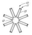
図14は、8本の弾性把持部材13を有する、図1の回収装置10の拡張した代替実施態様の断面図を示す。このようなバスケットは、比較的小さい目的物を捕捉し、保持するのに有利である。 FIG. 14 shows a cross-sectional view of an expanded alternative embodiment of the
図10は、遠端20をはんだで閉じた図1の回収装置10の代替実施態様の側面図を示す。チップ内のはんだ接合部27は研削および/または研磨で仕上げる。研磨したチップは、装置の使用中に繊細な組織の外傷を防止するのに役立つ。遠端を閉じても、内腔を通ってレーザ・ファイバまたは他の装置を供給し、罠に入れた結石を治療するには邪魔にならないが、ガイドワイヤ上に装置を供給する機能が望ましい場合は、開放した遠端が有利である。 FIG. 10 shows a side view of an alternative embodiment of the
図11は、遠位側の円筒55(カニューレ60の完全な部分)が弾性把持部材13の遠端41と相互接続するのではなく、はんだ接合部27などの締結具57を使用する、図1の装置10の代替回収バスケット54の側面図を示す。本明細書では、締結具57は、キャップ、かしめ、帯、溶接(スポット溶接を含む)または接着剤など、弾性把持部材を接合する任意の周知の方法を含むことができる。弾性把持部材13を結合するこの方法は、回収バスケット69を作成する代替方法を提供し、細長部材11を、図3に示した把持鉗子23の実施態様と同様に切削することができる。 11 uses a
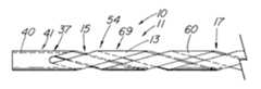
図15から図16は、螺旋形の医療用回収バスケット10を作成するよう回収装置10の弾性把持部材13を形成する、本発明の別の好ましい実施態様を示す。図15は、螺旋形スロット15を有し、拡張していない4本ワイヤの螺旋形バスケット54の側面図である。スロット15は、図1の実施態様と同様の方法で形成することができ、違いは切削手段またはカニューレ60自体を回転して、カニューレ60の円周で螺旋形になるスロット15を作成することである。この製造方法は、中実ワイヤで使用するよう適応させることもできる。図16は、図15の医療用回収装置の側面図を示す。非螺旋形の実施態様と同様、弾性把持部材13は、把持部材13が弛緩して応力のない状態になる拡大形状に、手作業で形成する。 FIGS. 15-16 illustrate another preferred embodiment of the present invention in which the elastic gripping
図17から図18は、バスケットを開いて結石24を回収するため、外部拘束機構ではなく起動部材29を含む、図1の装置10の代替実施態様の絵画的図を示す。図18は、起動部材29が前進して、結石24上で弾性把持部材13を閉じた、図16の回収装置10の絵画的図を示す。起動部材29の遠端42は、はんだ付けまたは他の方法で装置10の遠端20に取り付ける。拡張していない装置が内視鏡または導入器のシース内に含まれる間、起動部材29は十分に前進した位置にある。把持部材13が露出すると、起動部材29を引き戻してバスケット54を開放または拡大形状18になるよう操作し、次にこれを所定の位置にロックすることができる。バスケットを閉じるには、起動部材29をほぼ閉位置30へと十分に前進させ、結石24を罠に入れる。起動部材29は、ロック用ハブまたは他の周知の手段により装置の近端38で所定の位置にロックし、身体から引き出す間に結石24が誤って解放されるのを防止することができる。 FIGS. 17-18 show pictorial views of an alternative embodiment of the
起動部材は、結石を受けるのに使用可能な作業空間体積28のサイズを多少制限するが、外部シースを不要にするので、同じ直径の回収バスケット54を有する同軸装置より、装置が小さい内腔に入るか、より限定された空間に到達することができる。直径が小さい起動部材を使用して、内腔の中に追加の器具の空間を更にとるか、その目的のため、細長部材11に第2内腔を確保することができる。起動部材29は、前進して弾性把持部材を強制的に閉じる間、棒に有意の横方向の撓みがなく、十分に剛性がなければならない。カニューレ60に対する起動部材29の位置がバスケットの開閉を制御するので、弾性把持部材13は、他の実施態様のように拡大した形状か、圧縮形状である間、弛緩して応力のない状態にすることができる。後者の場合、カニューレ60に対して起動部材29を引っ込めると、バスケットが開いて拡大形状18になり、起動部材を前進させると、弾性把持部材13が弛緩して圧縮形状17に戻る。 The actuating member somewhat limits the size of the working
図19から図21は、弾性把持部材13を含む第1の材料40の連続体が、細長部材11の近位部分21にある他の材料66と相互接続する複数の強化ワイヤ31を含む。例示的実施態様では、回収装置10は、壁16に入れた平坦な弾性金属またはプラスチックの強化ワイヤ31を有するプラスチック管32を備える。細長部材11の遠位部分37でプラスチック管32の一部を除去することにより、露出した強化ワイヤ31は、拡大形状18に形成した後、弾性把持部材13として機能する。 19 to 21 include a plurality of reinforcing
図19は、弾性把持部材13が、プラスチック管32に入っている間、螺旋形編組パターン33を有する平坦な強化ワイヤ31である回収バスケット10を示す。弾性把持部材13は、プラスチック管32の遠端56から出るにつれ、方向転換するか直線にする、あるいは螺旋形編組33の自然な輪郭を辿ることができる。ワイヤが管32を出る管の遠端56で、ワイヤのいずれかを切断することにより、弾性把持部材13を露出した強化ワイヤ31より少なくすることが可能である。編組ワイヤ8本の強化管の例では、1方向(例えば螺旋状に時計回り)の螺旋形ワイヤ全部を切断して、他の方向に螺旋形を有する4本の露出ワイヤを残し、4本部材の螺旋形バスケットを形成することができる。遠端41は、エンド・キャップ34または他の周知の手段など、締結具57で結合することができる。回収バスケット54を作成する別の代替方法は、図1の遠位側円筒と同様の遠端で元のプラスチック管32の一部を残し、弾性把持部材13の遠端41を相互接続する。 FIG. 19 shows the
図20は、強化ワイヤ31が螺旋形に巻いているのではなく、細長部材11の縦軸43と整列する、本発明の別の好ましい実施態様を示す。このタイプのバスケットは、通常は、ワイヤがプラスチック管32の遠端を出るにつれ、それを方向転換または切断する必要がない。 FIG. 20 shows another preferred embodiment of the present invention in which the reinforcing
図21は、固定していない弾性把持要素が把持鉗子23を含む、図18および図19の装置の実施態様を示す。弾性把持部材13の遠端41を内側に変形して、目標物の捕捉および保持を容易にすることができる。 FIG. 21 shows an embodiment of the apparatus of FIGS. 18 and 19 in which the unsecured elastic gripping element includes gripping
本発明の回収装置10は、使用する前に従来の手順で殺菌できる医療用等級の材料で構成することが好ましい。回収装置10は比較的安価な合成および金属材料で作成でき、したがって装置10は1回使用した後、再殺菌して再使用するのではなく、廃棄できるので都合がよい。しかし、このような再使用も可能である。 The
言うまでもなく、構造に関する前記説明およびその他の詳細は、本発明の回収装置10を特定の外科的技術を実行するために順応させるよう、変更することができる。 Of course, the above description and other details regarding the structure can be modified to adapt the
以上説明したように、本発明の回収装置10は、様々な意味で従来技術の装置より特に有利であることが明白である。最も重要なことは、本発明は、装置(および特にその外部シース)が既存の回収または抽出装置の外径よりはるかに小さい全体的外径にできる点で、特に有利なことである。実際、本発明の回収装置は、わずか1フレンチ(0.33mm)の外径にすることができる。本発明の回収装置は、既存の装置で到達できるよりはるかに深い体内の位置から石、結石、凝固物、異物などの捕捉および除去、抽出および/または回収できるよう予想される。楔形ワイヤから形成するバスケット、把持器または他の噛合い手段は、その小さい直径にもかかわらず、良好な捻りおよび曲げに対する抵抗力を呈し、本発明の好ましい実施態様で述べたように、円形ワイヤと同様に螺旋形に形成し、維持することができる。本発明により全径が小さくなったので、使用中に患者に外傷を与える危険も低下するはずである。 As explained above, it is clear that the
前記のように、本発明の回収装置は、泌尿器処置、胆管処置、血管処置および身体の種々の空洞から異物を回収する処置など、多種多様な処置に用途があると予想される。更に、カニューレまたは管から形成される本発明の回収装置は、レーザ・ファイバまたは他の治療装置を導入する機能を提供し、ガイド・ワイヤ上に回収装置を供給して体内での配置を容易にする。 As described above, the recovery device of the present invention is expected to find use in a wide variety of procedures, such as urological procedures, bile duct procedures, vascular procedures, and procedures for recovering foreign bodies from various cavities of the body. In addition, the retrieval device of the present invention, formed from a cannula or tube, provides the ability to introduce a laser fiber or other treatment device, supplying the retrieval device over a guide wire to facilitate placement in the body. To do.
10 本発明の医療用回収装置
11 細長い円筒形部材
13 弾性把持部材
17 圧縮形状
18 拡大形状
19 近位閉円筒
20 遠端
21 近位部分
37 遠位部分
38 近端
40 第1の材料
69 螺旋形バスケット10
Claims (4)
Translated fromJapanese近端(38)と遠端(20)と、その間に遠位部分(37)と近位部分(39)を有する細長い円筒形部材(11)を有し、
前記遠位部分(37)と近位部分(39)との間で、前記円筒形部材(11)から複数の細長い弾性把持部材(13)が形成され、
前記複数の弾性把持部材(13)は、収縮状態(17)と拡大状態(18)との間で操作可能であり、
前記複数の弾性把持部材は、前記拡大状態で異物を収納可能であり、前記収縮状態で前記弾性把持部材間に間隙(15)が形成され、
前記細長い円筒形部材(11)と前記弾性把持部材(13)とは、1本の連続する金属要素から形成され、
前記弾性把持部材(13)は、前記遠端(20)で結合される
ことを特徴とする医療用回収装置(10)。In the medical recovery device (10),
An elongated cylindrical member (11) having a proximal end (38) and a distal end (20) and a distal portion (37) and a proximal portion (39) therebetween;
A plurality of elongated elastic gripping members (13) are formed from the cylindrical member (11) between the distal portion (37) and the proximal portion (39);
The plurality of elastic gripping members (13) are operable between a contracted state (17) and an expanded state (18),
The plurality of elastic gripping members can store foreign substances in the expanded state, and a gap (15) is formed between the elastic gripping members in the contracted state,
The elongated cylindrical member (11) and the elastic gripping member (13) are formed from one continuous metal element,
The medical recovery device (10), wherein the elastic gripping member (13) is coupled at the far end (20).
The medical retrieval device (10) according to any of claims 1-3, wherein the distal portion (37) has an open end.
Applications Claiming Priority (2)
| Application Number | Priority Date | Filing Date | Title |
|---|---|---|---|
| US7954098P | 1998-03-27 | 1998-03-27 | |
| US60/079,540 | 1998-03-27 |
Related Parent Applications (1)
| Application Number | Title | Priority Date | Filing Date |
|---|---|---|---|
| JP2000537486ADivisionJP4528438B2 (en) | 1998-03-27 | 1999-03-26 | Medical recovery device |
Publications (2)
| Publication Number | Publication Date |
|---|---|
| JP2008188439Atrue JP2008188439A (en) | 2008-08-21 |
| JP4982638B2 JP4982638B2 (en) | 2012-07-25 |
Family
ID=22151195
Family Applications (2)
| Application Number | Title | Priority Date | Filing Date |
|---|---|---|---|
| JP2000537486AExpired - LifetimeJP4528438B2 (en) | 1998-03-27 | 1999-03-26 | Medical recovery device |
| JP2008072303AExpired - LifetimeJP4982638B2 (en) | 1998-03-27 | 2008-03-19 | Medical recovery device |
Family Applications Before (1)
| Application Number | Title | Priority Date | Filing Date |
|---|---|---|---|
| JP2000537486AExpired - LifetimeJP4528438B2 (en) | 1998-03-27 | 1999-03-26 | Medical recovery device |
Country Status (11)
| Country | Link |
|---|---|
| US (1) | US6500182B2 (en) |
| EP (1) | EP1063926B1 (en) |
| JP (2) | JP4528438B2 (en) |
| KR (1) | KR20010042218A (en) |
| AT (1) | ATE324835T1 (en) |
| AU (1) | AU746955B2 (en) |
| CA (1) | CA2323623C (en) |
| DE (1) | DE69931152T2 (en) |
| DK (1) | DK1063926T3 (en) |
| ES (1) | ES2264257T3 (en) |
| WO (1) | WO1999048429A1 (en) |
Cited By (2)
| Publication number | Priority date | Publication date | Assignee | Title |
|---|---|---|---|---|
| KR101782250B1 (en)* | 2016-02-29 | 2017-09-27 | 가톨릭대학교 산학협력단 | stone removal device |
| JP2021118846A (en)* | 2020-01-23 | 2021-08-12 | ジャイラス エーシーエムアイ インク | Backward movement reversal crushing device |
Families Citing this family (257)
| Publication number | Priority date | Publication date | Assignee | Title |
|---|---|---|---|---|
| IL128261A0 (en) | 1999-01-27 | 1999-11-30 | Disc O Tech Medical Tech Ltd | Expandable element |
| JP2002503140A (en)* | 1998-04-23 | 2002-01-29 | サイムド ライフ システムズ,インコーポレイテッド | Non-traumatic medical recovery device |
| US7621950B1 (en) | 1999-01-27 | 2009-11-24 | Kyphon Sarl | Expandable intervertebral spacer |
| US6709465B2 (en) | 1999-03-18 | 2004-03-23 | Fossa Medical, Inc. | Radially expanding ureteral device |
| US7214229B2 (en)* | 1999-03-18 | 2007-05-08 | Fossa Medical, Inc. | Radially expanding stents |
| US6893450B2 (en)* | 1999-03-26 | 2005-05-17 | Cook Urological Incorporated | Minimally-invasive medical retrieval device |
| US6620172B1 (en)* | 1999-07-01 | 2003-09-16 | Medsource Technologies, Inc. | Entraining biological calculi |
| GB0015113D0 (en) | 2000-06-20 | 2000-08-09 | Angiomed Ag | Tool for removing object from the body of a patient |
| DE60138030D1 (en)* | 2000-09-14 | 2009-04-30 | Cook Urological Inc | MINIMALLY INVASIVE APPARATUS FOR COLLECTING OBJECTS IN HOLLOWERS |
| US7976648B1 (en) | 2000-11-02 | 2011-07-12 | Abbott Cardiovascular Systems Inc. | Heat treatment for cold worked nitinol to impart a shape setting capability without eventually developing stress-induced martensite |
| US6602272B2 (en)* | 2000-11-02 | 2003-08-05 | Advanced Cardiovascular Systems, Inc. | Devices configured from heat shaped, strain hardened nickel-titanium |
| US7713275B2 (en) | 2000-11-03 | 2010-05-11 | Cook Incorporated | Medical grasping device |
| US7727253B2 (en) | 2000-11-03 | 2010-06-01 | Cook Incorporated | Medical grasping device having embolic protection |
| US7753917B2 (en) | 2000-11-03 | 2010-07-13 | Cook Incorporated | Medical grasping device |
| US7776052B2 (en)* | 2000-11-03 | 2010-08-17 | Cook Incorporated | Medical grasping device |
| US7410490B2 (en)* | 2000-11-15 | 2008-08-12 | Omnitech Systems, Inc. | Surgical device |
| US20050010235A1 (en)* | 2003-07-09 | 2005-01-13 | Vandusseldorp Gregg A. | Surgical device |
| US6679893B1 (en)* | 2000-11-16 | 2004-01-20 | Chestnut Medical Technologies, Inc. | Grasping device and method of use |
| US6855161B2 (en) | 2000-12-27 | 2005-02-15 | Advanced Cardiovascular Systems, Inc. | Radiopaque nitinol alloys for medical devices |
| EP1294286B1 (en) | 2001-01-08 | 2005-12-07 | Boston Scientific Limited | Retrieval basket with releasable tip |
| US6743237B2 (en)* | 2001-01-17 | 2004-06-01 | Innon Holdings, Llc | Endoscopic stone extraction device with improved basket |
| JP4723104B2 (en)* | 2001-02-28 | 2011-07-13 | Hoya株式会社 | Endoscopic wire loop treatment tool |
| US7101379B2 (en) | 2001-04-02 | 2006-09-05 | Acmi Corporation | Retrieval basket for a surgical device and system and method for manufacturing same |
| US6800090B2 (en) | 2001-05-14 | 2004-10-05 | Cardiac Dimensions, Inc. | Mitral valve therapy device, system and method |
| US6814739B2 (en)* | 2001-05-18 | 2004-11-09 | U.S. Endoscopy Group, Inc. | Retrieval device |
| US6951570B2 (en) | 2001-07-02 | 2005-10-04 | Rubicon Medical, Inc. | Methods, systems, and devices for deploying a filter from a filter device |
| US8021372B2 (en) | 2001-07-05 | 2011-09-20 | Annex Medical, Inc. | Medical retrieval device with independent rotational means |
| JP2003093395A (en)* | 2001-09-21 | 2003-04-02 | Asahi Intecc Co Ltd | Medical treatment tools |
| US6824562B2 (en) | 2002-05-08 | 2004-11-30 | Cardiac Dimensions, Inc. | Body lumen device anchor, device and assembly |
| US7635387B2 (en) | 2001-11-01 | 2009-12-22 | Cardiac Dimensions, Inc. | Adjustable height focal tissue deflector |
| US7179282B2 (en) | 2001-12-05 | 2007-02-20 | Cardiac Dimensions, Inc. | Device and method for modifying the shape of a body organ |
| US6976995B2 (en) | 2002-01-30 | 2005-12-20 | Cardiac Dimensions, Inc. | Fixed length anchor and pull mitral valve device and method |
| US6676668B2 (en)* | 2001-12-12 | 2004-01-13 | C.R. Baed | Articulating stone basket |
| US6958074B2 (en)* | 2002-01-07 | 2005-10-25 | Cordis Corporation | Releasable and retrievable vascular filter system |
| US7037313B2 (en)* | 2002-03-19 | 2006-05-02 | Fibrex, Llc | Apparatus for stripping fibrin from a catheter |
| US20040024289A1 (en)* | 2002-04-29 | 2004-02-05 | Hugh Trout | Method and apparatus for supporting a surgical component |
| CA2877641C (en) | 2002-05-08 | 2017-01-17 | Cardiac Dimensions Pty. Ltd. | Device and method for modifying the shape of a body organ |
| US7125413B2 (en) | 2002-06-20 | 2006-10-24 | Scimed Life Systems, Inc. | Endoscopic fundoplication devices and methods for treatment of gastroesophageal reflux disease |
| EP1545349A1 (en)* | 2002-07-12 | 2005-06-29 | Cook Urological Inc. | Flexible cannula shaft |
| DE10233085B4 (en) | 2002-07-19 | 2014-02-20 | Dendron Gmbh | Stent with guide wire |
| US8425549B2 (en) | 2002-07-23 | 2013-04-23 | Reverse Medical Corporation | Systems and methods for removing obstructive matter from body lumens and treating vascular defects |
| US8043303B2 (en)* | 2002-10-04 | 2011-10-25 | Cook Medical Technologies Llc | Handle for interchangeable medical device |
| WO2004032769A1 (en)* | 2002-10-04 | 2004-04-22 | Cook Urological, Incorporated | Rigid extractor with wire basket |
| US7837729B2 (en) | 2002-12-05 | 2010-11-23 | Cardiac Dimensions, Inc. | Percutaneous mitral valve annuloplasty delivery system |
| US7316708B2 (en) | 2002-12-05 | 2008-01-08 | Cardiac Dimensions, Inc. | Medical device delivery system |
| US7678119B2 (en) | 2003-01-15 | 2010-03-16 | Scimed Life Systems, Inc. | Medical retrieval device with frangible basket |
| US7314485B2 (en) | 2003-02-03 | 2008-01-01 | Cardiac Dimensions, Inc. | Mitral valve device using conditioned shape memory alloy |
| ES2545328T3 (en) | 2003-03-14 | 2015-09-10 | Depuy Spine, Inc. | Bone cement hydraulic injection device in percutaneous vertebroplasty |
| US8052694B2 (en)* | 2003-03-19 | 2011-11-08 | Boston Scientific Scimed, Inc. | Device for manipulating material in a tissue |
| US7909862B2 (en)* | 2003-03-19 | 2011-03-22 | Cook Medical Technologies Llc | Delivery systems and methods for deploying expandable intraluminal medical devices |
| US8066713B2 (en) | 2003-03-31 | 2011-11-29 | Depuy Spine, Inc. | Remotely-activated vertebroplasty injection device |
| US7559934B2 (en) | 2003-04-07 | 2009-07-14 | Scimed Life Systems, Inc. | Beaded basket retrieval device |
| US9101383B1 (en) | 2003-04-25 | 2015-08-11 | Annex Medical, Inc. | Medical retrieval device |
| US7942892B2 (en) | 2003-05-01 | 2011-05-17 | Abbott Cardiovascular Systems Inc. | Radiopaque nitinol embolic protection frame |
| US20040220654A1 (en) | 2003-05-02 | 2004-11-04 | Cardiac Dimensions, Inc. | Device and method for modifying the shape of a body organ |
| US7887582B2 (en) | 2003-06-05 | 2011-02-15 | Cardiac Dimensions, Inc. | Device and method for modifying the shape of a body organ |
| US8415407B2 (en) | 2004-03-21 | 2013-04-09 | Depuy Spine, Inc. | Methods, materials, and apparatus for treating bone and other tissue |
| US7731722B2 (en) | 2003-07-31 | 2010-06-08 | Vance Products Incorporated | Ureteral backstop filter and retrieval device |
| US7377925B2 (en)* | 2003-09-16 | 2008-05-27 | Minimally Invasive Devices, Llc | Fragmentation and extraction basket |
| US7727227B2 (en)* | 2003-09-18 | 2010-06-01 | Boston Scientific Scimed, Inc. | Medical retrieval devices with laser and retrieval assembly |
| US8388630B2 (en)* | 2003-09-18 | 2013-03-05 | Boston Scientific Scimed, Inc. | Medical retrieval devices and methods |
| US8579908B2 (en) | 2003-09-26 | 2013-11-12 | DePuy Synthes Products, LLC. | Device for delivering viscous material |
| US7208008B2 (en)* | 2003-10-02 | 2007-04-24 | Medtronic Vascular, Inc. | Balloonless direct stenting device |
| US9526616B2 (en) | 2003-12-19 | 2016-12-27 | Cardiac Dimensions Pty. Ltd. | Mitral valve annuloplasty device with twisted anchor |
| US7794496B2 (en) | 2003-12-19 | 2010-09-14 | Cardiac Dimensions, Inc. | Tissue shaping device with integral connector and crimp |
| US20060271174A1 (en)* | 2003-12-19 | 2006-11-30 | Gregory Nieminen | Mitral Valve Annuloplasty Device with Wide Anchor |
| US7837728B2 (en) | 2003-12-19 | 2010-11-23 | Cardiac Dimensions, Inc. | Reduced length tissue shaping device |
| US20050192592A1 (en)* | 2004-02-27 | 2005-09-01 | Cook Urological Incorporated | Self-tensioning handle for endoscopic device |
| US20050228417A1 (en)* | 2004-03-26 | 2005-10-13 | Teitelbaum George P | Devices and methods for removing a matter from a body cavity of a patient |
| CA2568446A1 (en)* | 2004-05-06 | 2005-11-17 | Boston Scientific Limited | Stone retrieval device and related methods of manufacture |
| US20050261705A1 (en)* | 2004-05-21 | 2005-11-24 | Gist Christopher W | Device to remove kidney stones |
| JP4505658B2 (en)* | 2004-05-25 | 2010-07-21 | ユー.エス. エンドスコピー グループ, インコーポレイテッド | Collection device |
| CN101065080B (en) | 2004-07-30 | 2021-10-29 | 德普伊新特斯产品有限责任公司 | Materials and Instruments for Manipulating Bone and Other Tissues |
| JP2006075232A (en)* | 2004-09-07 | 2006-03-23 | Terumo Corp | Wire for removing endovascular foreign body, and medical appliance |
| US7824415B2 (en) | 2004-09-15 | 2010-11-02 | Boston Scientific Scimed, Inc. | Atraumatic medical device |
| US20060074409A1 (en)* | 2004-10-05 | 2006-04-06 | Scimed Life Systems, Inc. | Detachable shaft medical retrieval device and related methods of use |
| US20060184076A1 (en)* | 2004-12-01 | 2006-08-17 | Gill Robert P | Ultrasonic device and method for treating stones within the body |
| US20060116693A1 (en)* | 2004-12-01 | 2006-06-01 | Weisenburgh William B Ii | Apparatus and method for stone capture and removal |
| EP1855619A4 (en) | 2005-01-20 | 2013-10-02 | Cardiac Dimensions Inc | Tissue shaping device |
| WO2006080113A1 (en)* | 2005-01-26 | 2006-08-03 | Nihon University | Medical appliance for treating inside of biological duct |
| US8523879B1 (en) | 2005-03-31 | 2013-09-03 | Stuart J. Lind | Stone retriever for flexible endoscopes having small diameter working channels |
| US8287535B2 (en) | 2005-05-11 | 2012-10-16 | Mayo Foundation For Medical Education And Research | Apparatus and methods for internal surgical procedures |
| US9381024B2 (en) | 2005-07-31 | 2016-07-05 | DePuy Synthes Products, Inc. | Marked tools |
| US9918767B2 (en) | 2005-08-01 | 2018-03-20 | DePuy Synthes Products, Inc. | Temperature control system |
| US8998923B2 (en) | 2005-08-31 | 2015-04-07 | Spinealign Medical, Inc. | Threaded bone filling material plunger |
| US20070067034A1 (en)* | 2005-08-31 | 2007-03-22 | Chirico Paul E | Implantable devices and methods for treating micro-architecture deterioration of bone tissue |
| US8597303B2 (en)* | 2005-11-03 | 2013-12-03 | Cook Medical Technologies Llc | Articulating basket with simultaneous basket extension or basket retraction |
| US8360629B2 (en) | 2005-11-22 | 2013-01-29 | Depuy Spine, Inc. | Mixing apparatus having central and planetary mixing elements |
| EP1951159B1 (en)* | 2005-11-23 | 2015-08-19 | Trinity Orthopedics | Percutaneous transpedicular access, fusion, discectomy, and stabilization system |
| US9107733B2 (en)* | 2006-01-13 | 2015-08-18 | W. L. Gore & Associates, Inc. | Removable blood conduit filter |
| WO2007098376A2 (en)* | 2006-02-17 | 2007-08-30 | The Catheter Exchange, Inc. | Device for placing an occlusion removing structure in a tubular structure with a substantially closed distal end |
| US20070198032A1 (en)* | 2006-02-22 | 2007-08-23 | Ethicon Endo-Surgery, Inc. | Methods and devices for fastener removal |
| US7473232B2 (en) | 2006-02-24 | 2009-01-06 | Boston Scientific Scimed, Inc. | Obtaining a tissue sample |
| US7503932B2 (en) | 2006-04-11 | 2009-03-17 | Cardiac Dimensions, Inc. | Mitral valve annuloplasty device with vena cava anchor |
| CA2651175A1 (en)* | 2006-05-03 | 2007-11-15 | Wilson-Cook Medical, Inc. | Lithotripsy compatible wire basket |
| EP2020965B1 (en) | 2006-05-04 | 2017-04-19 | Cook Medical Technologies LLC | Self-orienting delivery system |
| US11285005B2 (en) | 2006-07-17 | 2022-03-29 | Cardiac Dimensions Pty. Ltd. | Mitral valve annuloplasty device with twisted anchor |
| US8361084B2 (en)* | 2006-09-01 | 2013-01-29 | Boston Scientific Scimed, Inc. | Medical retrieval baskets |
| AU2007297097A1 (en) | 2006-09-14 | 2008-03-20 | Depuy Spine, Inc. | Bone cement and methods of use thereof |
| US8584921B2 (en) | 2006-10-06 | 2013-11-19 | Covidien Lp | Surgical instrument with articulating tool assembly |
| US8858567B2 (en)* | 2006-10-14 | 2014-10-14 | Rafic Saleh | Surgical retrieval device and method |
| US8950929B2 (en) | 2006-10-19 | 2015-02-10 | DePuy Synthes Products, LLC | Fluid delivery system |
| US20080269774A1 (en) | 2006-10-26 | 2008-10-30 | Chestnut Medical Technologies, Inc. | Intracorporeal Grasping Device |
| US8961551B2 (en) | 2006-12-22 | 2015-02-24 | The Spectranetics Corporation | Retractable separating systems and methods |
| US9028520B2 (en) | 2006-12-22 | 2015-05-12 | The Spectranetics Corporation | Tissue separating systems and methods |
| DE102007021966A1 (en) | 2007-05-10 | 2008-11-13 | Medi-Globe Gmbh | Sling device and catch basket manufacturing method for extracting stone and/or fabric part from body cavity of person, involves connecting material strands at outer end parts with actuator to make pulling movement of strands |
| US8591521B2 (en) | 2007-06-08 | 2013-11-26 | United States Endoscopy Group, Inc. | Retrieval device |
| EP3679874B1 (en)* | 2007-06-08 | 2024-04-10 | United States Endoscopy Group, Inc. | Retrieval device |
| US7879066B2 (en)* | 2007-07-13 | 2011-02-01 | Percutaneous Sustems, Inc. | Apparatus for occluding body lumens |
| US8475489B2 (en)* | 2007-07-13 | 2013-07-02 | Percutaneous Systems, Inc. | Apparatus for occluding body lumens |
| US11337714B2 (en) | 2007-10-17 | 2022-05-24 | Covidien Lp | Restoring blood flow and clot removal during acute ischemic stroke |
| US8088140B2 (en) | 2008-05-19 | 2012-01-03 | Mindframe, Inc. | Blood flow restorative and embolus removal methods |
| JP2011505201A (en) | 2007-11-30 | 2011-02-24 | クック・インコーポレイテッド | Method and apparatus for vascular therapy |
| IL188067A (en)* | 2007-12-12 | 2011-12-29 | Lithotech Medical Ltd | Device for fragmenting and removing concretions from body ducts and cavities |
| WO2009079506A1 (en)* | 2007-12-17 | 2009-06-25 | Boston Scientific Scimed, Inc. | Retrieval device |
| US20090192485A1 (en)* | 2008-01-28 | 2009-07-30 | Heuser Richard R | Snare device |
| WO2009105699A1 (en) | 2008-02-22 | 2009-08-27 | Endologix, Inc. | Design and method of placement of a graft or graft system |
| JP5457373B2 (en) | 2008-02-22 | 2014-04-02 | コヴィディエン リミテッド パートナーシップ | Device for blood flow recovery |
| US8006594B2 (en) | 2008-08-11 | 2011-08-30 | Cardiac Dimensions, Inc. | Catheter cutting tool |
| WO2010065556A1 (en) | 2008-12-01 | 2010-06-10 | Percutaneous Systems, Inc. | Methods and systems for capturing and removing urinary stones from body cavities |
| US8770460B2 (en)* | 2008-12-23 | 2014-07-08 | George E. Belzer | Shield for surgical stapler and method of use |
| US20110054587A1 (en) | 2009-04-28 | 2011-03-03 | Endologix, Inc. | Apparatus and method of placement of a graft or graft system |
| KR20120047231A (en) | 2009-06-17 | 2012-05-11 | 트리니티 올쏘피딕스, 엘엘씨 | Expanding intervertebral device and methods of use |
| US9220523B2 (en) | 2009-09-14 | 2015-12-29 | The Spectranetics Corporation | Snaring systems and methods |
| US8662370B2 (en)* | 2010-04-08 | 2014-03-04 | Hidehisa Thomas Takei | Introducer system and assembly for surgical staplers |
| US8974469B2 (en) | 2010-04-22 | 2015-03-10 | Medical Device Technologies, Inc. | Snare |
| US9370377B2 (en) | 2010-05-26 | 2016-06-21 | endoMedical Concepts Inc. | Extraction device |
| JP5728779B2 (en)* | 2010-07-23 | 2015-06-03 | 国立大学法人大阪大学 | Intravascular hemostasis catheter |
| WO2012037341A1 (en) | 2010-09-15 | 2012-03-22 | The United States Of America, As Represented By The Secretary, National Institutes Of Health | Devices for transcatheter cerclage annuloplasty |
| US9039749B2 (en) | 2010-10-01 | 2015-05-26 | Covidien Lp | Methods and apparatuses for flow restoration and implanting members in the human body |
| US20120109279A1 (en) | 2010-11-02 | 2012-05-03 | Endologix, Inc. | Apparatus and method of placement of a graft or graft system |
| WO2013016275A1 (en) | 2011-07-22 | 2013-01-31 | Cook Medical Technologies Llc | Irrigation devices adapted to be used with a light source for the identification and treatment of bodily passages |
| US9101342B2 (en) | 2011-07-22 | 2015-08-11 | Rafic Saleh | Surgical retrieval apparatus and method with semi-rigidly extendable and collapsible basket |
| US20140364866A1 (en)* | 2012-01-06 | 2014-12-11 | University Of Louisville Research Foundation, Inc. | Endoscopic snare device |
| EP3628247B1 (en) | 2012-02-07 | 2022-08-10 | Intervene, Inc. | System for endoluminal valve creation |
| US9393126B2 (en)* | 2012-04-20 | 2016-07-19 | Peter L. Mayer | Bilaterally placed disc prosthesis for spinal implant and method of bilateral placement |
| US9364339B2 (en)* | 2012-04-30 | 2016-06-14 | Peter L. Mayer | Unilaterally placed expansile spinal prosthesis |
| DE102012010687B4 (en)* | 2012-05-30 | 2021-08-19 | ADMEDES GmbH | A method for producing a body implant, an assembly comprising a guide wire and a body implant, and a medical instrument |
| US9078683B2 (en) | 2012-06-18 | 2015-07-14 | Lumenis Ltd. | Systems and methods for a multifunction surgical apparatus |
| US9413896B2 (en) | 2012-09-14 | 2016-08-09 | The Spectranetics Corporation | Tissue slitting methods and systems |
| DE102012021729B3 (en) | 2012-11-05 | 2013-12-05 | Universitätsklinikum Freiburg | Device for detaching wall-shaped thrombi from a body vessel |
| JP6317751B2 (en) | 2012-11-08 | 2018-04-25 | ボストン サイエンティフィック サイムド,インコーポレイテッドBoston Scientific Scimed,Inc. | System for performing medical procedures |
| DE102013113263A1 (en)* | 2012-12-17 | 2014-06-18 | Acandis Gmbh & Co. Kg | Medical instrument for intravascular procedures and manufacturing processes |
| WO2014110460A1 (en) | 2013-01-10 | 2014-07-17 | Intervene, Inc. | Systems and methods for endoluminal valve creation |
| US9895055B2 (en) | 2013-02-28 | 2018-02-20 | Cook Medical Technologies Llc | Medical devices, systems, and methods for the visualization and treatment of bodily passages |
| US9883885B2 (en) | 2013-03-13 | 2018-02-06 | The Spectranetics Corporation | System and method of ablative cutting and pulsed vacuum aspiration |
| US9283040B2 (en) | 2013-03-13 | 2016-03-15 | The Spectranetics Corporation | Device and method of ablative cutting with helical tip |
| US9456872B2 (en) | 2013-03-13 | 2016-10-04 | The Spectranetics Corporation | Laser ablation catheter |
| US9291663B2 (en) | 2013-03-13 | 2016-03-22 | The Spectranetics Corporation | Alarm for lead insulation abnormality |
| US10383691B2 (en) | 2013-03-13 | 2019-08-20 | The Spectranetics Corporation | Last catheter with helical internal lumen |
| US9775675B2 (en) | 2013-03-14 | 2017-10-03 | The Charlotte-Mecklenburg Hospital Authority | Ureteroscope and associated method for the minimally invasive treatment of urinary stones |
| US10835279B2 (en) | 2013-03-14 | 2020-11-17 | Spectranetics Llc | Distal end supported tissue slitting apparatus |
| US9980743B2 (en) | 2013-03-15 | 2018-05-29 | The Spectranetics Corporation | Medical device for removing an implanted object using laser cut hypotubes |
| US10448999B2 (en) | 2013-03-15 | 2019-10-22 | The Spectranetics Corporation | Surgical instrument for removing an implanted object |
| US9668765B2 (en) | 2013-03-15 | 2017-06-06 | The Spectranetics Corporation | Retractable blade for lead removal device |
| WO2014151814A1 (en) | 2013-03-15 | 2014-09-25 | The Spectranetics Corporation | Surgical instrument for removing an implanted object |
| US10842532B2 (en) | 2013-03-15 | 2020-11-24 | Spectranetics Llc | Medical device for removing an implanted object |
| US9918737B2 (en) | 2013-03-15 | 2018-03-20 | The Spectranetics Corporation | Medical device for removing an implanted object |
| US10188411B2 (en) | 2013-04-16 | 2019-01-29 | Calcula Technologies, Inc. | Everting balloon for medical devices |
| US8974472B2 (en) | 2013-04-16 | 2015-03-10 | Calcula Technologies, Inc. | Method for removing kidney stones |
| US10219864B2 (en) | 2013-04-16 | 2019-03-05 | Calcula Technologies, Inc. | Basket and everting balloon with simplified design and control |
| US9867630B2 (en) | 2013-06-11 | 2018-01-16 | Innon Holdings, Llc | Endoscopic stone-extraction device |
| EP3666227A1 (en) | 2013-06-14 | 2020-06-17 | Avantec Vascular Corporation | Inferior vena cava filter and retrieval systems |
| US10071243B2 (en) | 2013-07-31 | 2018-09-11 | Medtronic, Inc. | Fixation for implantable medical devices |
| US9549748B2 (en) | 2013-08-01 | 2017-01-24 | Cook Medical Technologies Llc | Methods of locating and treating tissue in a wall defining a bodily passage |
| JP6151452B2 (en) | 2013-08-16 | 2017-06-21 | カーディアック ペースメイカーズ, インコーポレイテッド | Delivery device and method for a leadless heart device |
| JP6182675B2 (en) | 2013-08-16 | 2017-08-16 | カーディアック ペースメイカーズ, インコーポレイテッド | Leadless cardiac pacemaker and collection device |
| BR112016003148B1 (en) | 2013-08-16 | 2021-01-12 | Cardiac Pacemakers, Inc. | non-shunt cardiac pacing devices |
| US9480850B2 (en) | 2013-08-16 | 2016-11-01 | Cardiac Pacemakers, Inc. | Leadless cardiac pacemaker and retrieval device |
| US10722723B2 (en) | 2013-08-16 | 2020-07-28 | Cardiac Pacemakers, Inc. | Delivery devices and methods for leadless cardiac devices |
| US9393427B2 (en) | 2013-08-16 | 2016-07-19 | Cardiac Pacemakers, Inc. | Leadless cardiac pacemaker with delivery and/or retrieval features |
| US10842993B2 (en) | 2013-08-16 | 2020-11-24 | Cardiac Pacemakers, Inc. | Leadless cardiac pacing devices |
| US9492674B2 (en) | 2013-08-16 | 2016-11-15 | Cardiac Pacemakers, Inc. | Leadless cardiac pacemaker with delivery and/or retrieval features |
| US9572591B2 (en) | 2013-09-03 | 2017-02-21 | United States Endoscopy Group, Inc. | Endoscopic snare device |
| US10076399B2 (en) | 2013-09-13 | 2018-09-18 | Covidien Lp | Endovascular device engagement |
| WO2015048565A2 (en) | 2013-09-27 | 2015-04-02 | Intervene, Inc. | Visualization devices, systems, and methods for informing intravascular procedures on blood vessel valves |
| US9282985B2 (en) | 2013-11-11 | 2016-03-15 | Gyrus Acmi, Inc. | Aiming beam detection for safe laser lithotripsy |
| JP6637430B2 (en) | 2014-01-15 | 2020-01-29 | タフツ メディカル センター, インク.Tufts Medical Center, Inc. | Intravascular cerebrospinal fluid shunt |
| US9980715B2 (en) | 2014-02-05 | 2018-05-29 | Trinity Orthopedics, Llc | Anchor devices and methods of use |
| US9937323B2 (en) | 2014-02-28 | 2018-04-10 | Cook Medical Technologies Llc | Deflectable catheters, systems, and methods for the visualization and treatment of bodily passages |
| EP3113701B1 (en) | 2014-03-03 | 2020-07-22 | The Spectranetics Corporation | Multiple configuration surgical cutting device |
| US12053203B2 (en) | 2014-03-03 | 2024-08-06 | Spectranetics, Llc | Multiple configuration surgical cutting device |
| US10285720B2 (en) | 2014-03-11 | 2019-05-14 | Neuravi Limited | Clot retrieval system for removing occlusive clot from a blood vessel |
| WO2015148581A1 (en) | 2014-03-24 | 2015-10-01 | Intervene, Inc. | Devices, systems, and methods for controlled hydrodissection of vessel walls |
| US10667836B2 (en) | 2014-04-28 | 2020-06-02 | Boston Scientific Scimed, Inc. | Tissue resectors, hand operated tissue resecting systems, and associated methods |
| US10080887B2 (en) | 2014-04-29 | 2018-09-25 | Cardiac Pacemakers, Inc. | Leadless cardiac pacing devices including tissue engagement verification |
| WO2015168155A1 (en) | 2014-04-29 | 2015-11-05 | Cardiac Pacemakers, Inc. | Leadless cardiac pacemaker with retrieval features |
| US9254075B2 (en) | 2014-05-04 | 2016-02-09 | Gyrus Acmi, Inc. | Location of fragments during lithotripsy |
| US9259231B2 (en) | 2014-05-11 | 2016-02-16 | Gyrus Acmi, Inc. | Computer aided image-based enhanced intracorporeal lithotripsy |
| US10405924B2 (en) | 2014-05-30 | 2019-09-10 | The Spectranetics Corporation | System and method of ablative cutting and vacuum aspiration through primary orifice and auxiliary side port |
| US9655634B2 (en) | 2014-06-12 | 2017-05-23 | Innon Holdings, Llc | Endoscopic stone-extraction device |
| US10448962B2 (en) | 2014-06-12 | 2019-10-22 | Innon Holdings, Llc | Endoscopic stone-extraction device |
| JP6595513B2 (en) | 2014-06-13 | 2019-10-23 | ニューラヴィ・リミテッド | Device for removal of acute occlusions from blood vessels |
| US10792056B2 (en)* | 2014-06-13 | 2020-10-06 | Neuravi Limited | Devices and methods for removal of acute blockages from blood vessels |
| US10265086B2 (en) | 2014-06-30 | 2019-04-23 | Neuravi Limited | System for removing a clot from a blood vessel |
| US10195398B2 (en) | 2014-08-13 | 2019-02-05 | Cook Medical Technologies Llc | Tension member seal and securing mechanism for medical devices |
| US10463351B2 (en)* | 2014-10-15 | 2019-11-05 | Cook Medical Technologies Llc | Transitional geometry for an expandable medical device |
| CN107148293B (en) | 2014-10-31 | 2020-08-11 | 西瑞维斯克有限责任公司 | Method and system for treating hydrocephalus |
| JP6601501B2 (en) | 2014-11-04 | 2019-11-13 | ニプロ株式会社 | Catheter device internally provided with a longitudinal inflation element for compressing cancellous bone |
| US10278804B2 (en) | 2014-12-12 | 2019-05-07 | Avantec Vascular Corporation | IVC filter retrieval systems with releasable capture feature |
| EP3229729B1 (en) | 2014-12-12 | 2023-03-15 | Avantec Vascular Corporation | Ivc filter retrieval systems with interposed support members |
| WO2016100574A2 (en) | 2014-12-16 | 2016-06-23 | Intervene, Inc. | Intravascular devices, systems, and methods for the controlled dissection of body lumens |
| US9731113B2 (en) | 2014-12-30 | 2017-08-15 | The Spectranetics Corporation | Collapsing coil coupling for lead extension and extraction |
| US10576274B2 (en) | 2014-12-30 | 2020-03-03 | Spectranetics Llc | Expanding coil coupling for lead extension and extraction |
| US9884184B2 (en) | 2014-12-30 | 2018-02-06 | The Spectranetics Corporation | Wire hook coupling for lead extension and extraction |
| US10105533B2 (en) | 2014-12-30 | 2018-10-23 | The Spectranetics Corporation | Multi-loop coupling for lead extension and extraction |
| USD765243S1 (en) | 2015-02-20 | 2016-08-30 | The Spectranetics Corporation | Medical device handle |
| USD770616S1 (en) | 2015-02-20 | 2016-11-01 | The Spectranetics Corporation | Medical device handle |
| WO2017004265A1 (en) | 2015-06-30 | 2017-01-05 | Endologix, Inc. | Locking assembly for coupling guidewire to delivery system |
| US10272230B2 (en) | 2015-10-30 | 2019-04-30 | Cerevasc, Llc | Systems and methods for treating hydrocephalus |
| US10183087B2 (en)* | 2015-11-10 | 2019-01-22 | American Sterilizer Company | Cleaning and disinfecting composition |
| WO2017117427A1 (en)* | 2015-12-31 | 2017-07-06 | Cerevasc, Llc | Methods and systems for removing clots from blood vessels |
| US10099050B2 (en) | 2016-01-21 | 2018-10-16 | Medtronic, Inc. | Interventional medical devices, device systems, and fixation components thereof |
| US10463853B2 (en) | 2016-01-21 | 2019-11-05 | Medtronic, Inc. | Interventional medical systems |
| US10646247B2 (en) | 2016-04-01 | 2020-05-12 | Intervene, Inc. | Intraluminal tissue modifying systems and associated devices and methods |
| CN109069171A (en)* | 2016-04-14 | 2018-12-21 | 波士顿科学医学有限公司 | Medical system, device and correlation technique |
| JP6806791B2 (en)* | 2016-04-19 | 2021-01-06 | ジャイラス・エーシーエムアイ・インコーポレーテッド | Medical extraction device |
| WO2019046205A1 (en) | 2017-08-26 | 2019-03-07 | Macdonald, Stuart | Cardiac annuloplasty and pacing procedures, related devices and methods |
| US11007059B2 (en) | 2016-05-06 | 2021-05-18 | Transmural Systems Llc | Annuloplasty procedures, related devices and methods |
| US11039923B2 (en) | 2016-05-06 | 2021-06-22 | Transmural Systems Llc | Annuloplasty procedures, related devices and methods |
| US11980545B2 (en) | 2016-05-06 | 2024-05-14 | Transmural Systems Llc | Annuloplasty procedures, related devices and methods |
| US9974460B2 (en)* | 2016-05-06 | 2018-05-22 | Biosense Webster (Israel) Ltd. | Basket-shaped catheter with improved distal hub |
| EP3500191B1 (en) | 2016-08-17 | 2020-09-23 | Neuravi Limited | A clot retrieval system for removing occlusive clot from a blood vessel |
| US11839398B2 (en) | 2016-09-09 | 2023-12-12 | Endovascular Instruments, Inc. | Adjustable ring stripper for more efficiently and effectively removing plaque from arteries |
| WO2018071600A1 (en) | 2016-10-11 | 2018-04-19 | Cerevasc, Llc | Methods and systems for treating hydrocephalus |
| CN110167482A (en) | 2016-12-22 | 2019-08-23 | 阿万泰血管公司 | Systems, devices and methods for retrieval systems with tethers |
| US10786277B2 (en) | 2017-01-09 | 2020-09-29 | United State Endoscopy Group, Inc. | Retrieval device |
| US10925607B2 (en)* | 2017-02-28 | 2021-02-23 | Covidien Lp | Surgical stapling apparatus with staple sheath |
| US11771875B2 (en) | 2017-03-02 | 2023-10-03 | CereVasc, Inc. | Catheter systems and methods for medical procedures using catheters |
| US10390953B2 (en) | 2017-03-08 | 2019-08-27 | Cardiac Dimensions Pty. Ltd. | Methods and devices for reducing paravalvular leakage |
| US9743944B1 (en) | 2017-04-24 | 2017-08-29 | Calcula Technologies, Inc. | Stone retrieval balloon catheter |
| CN107049423A (en)* | 2017-06-01 | 2017-08-18 | 遵义医学院附属医院 | A kind of choledochoscope stone extraction basket |
| JP6688262B2 (en)* | 2017-07-13 | 2020-04-28 | トクセン工業株式会社 | Grasping forceps for endoscope |
| US20190021749A1 (en)* | 2017-07-19 | 2019-01-24 | Hoya Corporation | Universal retrieval device for removing obstructions from body lumens |
| US11490908B2 (en) | 2017-11-09 | 2022-11-08 | Contego Medical , Inc. | Thrombectomy device and methods of use |
| WO2019104355A1 (en) | 2017-11-27 | 2019-05-31 | Rafic Saleh | Endoscopic snare |
| EP3762083B1 (en) | 2018-03-08 | 2025-02-12 | CereVasc, Inc. | Systems for minimally invasive drug delivery to a subarachnoid space |
| US10595873B2 (en)* | 2018-04-19 | 2020-03-24 | Franklin Institute of Innovation, LLC | Surgical staplers and related methods |
| CN112584799A (en) | 2018-06-29 | 2021-03-30 | 阿万泰血管公司 | Systems and methods for implants and deployment devices |
| JP6587328B1 (en)* | 2018-09-03 | 2019-10-09 | 株式会社ツカサ精密 | Sheet insertion tool |
| ES2910600T3 (en) | 2019-03-04 | 2022-05-12 | Neuravi Ltd | Powered Clot Recovery Catheter |
| US11759632B2 (en) | 2019-03-28 | 2023-09-19 | Medtronic, Inc. | Fixation components for implantable medical devices |
| EP3791815B1 (en) | 2019-09-11 | 2024-06-26 | Neuravi Limited | Expandable mouth catheter |
| US11839725B2 (en) | 2019-11-27 | 2023-12-12 | Neuravi Limited | Clot retrieval device with outer sheath and inner catheter |
| US11779364B2 (en) | 2019-11-27 | 2023-10-10 | Neuravi Limited | Actuated expandable mouth thrombectomy catheter |
| US11944327B2 (en) | 2020-03-05 | 2024-04-02 | Neuravi Limited | Expandable mouth aspirating clot retrieval catheter |
| US11633198B2 (en) | 2020-03-05 | 2023-04-25 | Neuravi Limited | Catheter proximal joint |
| US11883043B2 (en) | 2020-03-31 | 2024-01-30 | DePuy Synthes Products, Inc. | Catheter funnel extension |
| US11759217B2 (en) | 2020-04-07 | 2023-09-19 | Neuravi Limited | Catheter tubular support |
| US11771501B2 (en) | 2020-06-23 | 2023-10-03 | Intervene, Inc. | Endovascular valve formation system with imaging capability |
| CN116113375A (en)* | 2020-07-27 | 2023-05-12 | 苏州徕瑞医疗技术有限公司 | A thrombus removal device |
| CN112472205B (en)* | 2020-11-25 | 2022-02-11 | 西安交通大学医学院第一附属医院 | Percutaneous transhepatic sinus lithotomy device based on hepatobiliary surgery |
| JP2023554000A (en) | 2020-12-14 | 2023-12-26 | カーディアック・ディメンションズ・プロプライエタリー・リミテッド | Modular preloaded medical implants and delivery systems |
| US11872354B2 (en) | 2021-02-24 | 2024-01-16 | Neuravi Limited | Flexible catheter shaft frame with seam |
| US11937839B2 (en) | 2021-09-28 | 2024-03-26 | Neuravi Limited | Catheter with electrically actuated expandable mouth |
| US12011186B2 (en) | 2021-10-28 | 2024-06-18 | Neuravi Limited | Bevel tip expandable mouth catheter with reinforcing ring |
| CN120324069B (en)* | 2025-06-18 | 2025-08-19 | 中国人民解放军海军军医大学第三附属医院 | A precision-controlled manipulator-assisted hepatobiliary surgical stone removal device |
Citations (12)
| Publication number | Priority date | Publication date | Assignee | Title |
|---|---|---|---|---|
| US2556783A (en)* | 1950-05-16 | 1951-06-12 | American Cystoscope Makers Inc | Surgical forceps |
| US3320957A (en)* | 1964-05-21 | 1967-05-23 | Sokolik Edward | Surgical instrument |
| JPS5534811A (en)* | 1978-09-01 | 1980-03-11 | Hitachi Ltd | Dc motor having wave-wound armature coil |
| JPS58188469A (en)* | 1982-04-27 | 1983-11-02 | オリンパス光学工業株式会社 | Laser probe for breaking stone |
| JPS61115550A (en)* | 1984-11-10 | 1986-06-03 | 株式会社トーキン | Catheter for catching stone |
| US5030201A (en)* | 1989-11-24 | 1991-07-09 | Aubrey Palestrant | Expandable atherectomy catheter device |
| JPH06154231A (en)* | 1991-05-03 | 1994-06-03 | Vance Prod Inc | Device for surgical therapy |
| JP2509918B2 (en)* | 1986-10-31 | 1996-06-26 | オリンパス光学工業株式会社 | Removal tool for foreign bodies in body cavity |
| US5643198A (en)* | 1990-12-14 | 1997-07-01 | Rocin Laboratories, Inc. | Power-assisted liposuction instrument and cannula assembly therefor |
| JPH105234A (en)* | 1996-06-24 | 1998-01-13 | Asahi Optical Co Ltd | Basket-type foreign body collection tool for endoscope |
| US5795322A (en)* | 1995-04-10 | 1998-08-18 | Cordis Corporation | Catheter with filter and thrombus-discharge device |
| US6443959B1 (en)* | 1999-02-16 | 2002-09-03 | Instruments Medicaux Gb Inc. | Surgical extractor |
Family Cites Families (17)
| Publication number | Priority date | Publication date | Assignee | Title |
|---|---|---|---|---|
| US4046150A (en)* | 1975-07-17 | 1977-09-06 | American Hospital Supply Corporation | Medical instrument for locating and removing occlusive objects |
| IT1126526B (en)* | 1979-12-07 | 1986-05-21 | Enrico Dormia | SURGICAL EXTRACTOR TO REMOVE FOREIGN BODIES THAT ARE FOUND IN THE NATURAL ROUTES OF THE HUMAN BODY, AS CALCULATIONS AND SIMILAR |
| US4393872A (en) | 1980-05-27 | 1983-07-19 | Eder Instrument Co., Inc. | Aspirating surgical forceps |
| EP0117894B1 (en) | 1983-02-08 | 1989-11-08 | Storz-Endoskop GmbH | Endoscope comprising a medical gripping instrument |
| US4611594A (en)* | 1984-04-11 | 1986-09-16 | Northwestern University | Medical instrument for containment and removal of calculi |
| US4625726A (en) | 1984-08-07 | 1986-12-02 | Duthoy Everette J | Kidney stone retriever |
| US4807626A (en) | 1985-02-14 | 1989-02-28 | Mcgirr Douglas B | Stone extractor and method |
| FR2685190B1 (en)* | 1991-12-23 | 1998-08-07 | Jean Marie Lefebvre | ROTARY ATHERECTOMY OR THROMBECTOMY DEVICE WITH CENTRIFUGAL TRANSVERSE DEVELOPMENT. |
| US5376094A (en) | 1993-08-19 | 1994-12-27 | Boston Scientific Corporation | Improved actuating handle with pulley system for providing mechanical advantage to a surgical working element |
| US5397320A (en)* | 1994-03-03 | 1995-03-14 | Essig; Mitchell N. | Dissecting surgical device and associated method |
| US5583325A (en) | 1995-04-26 | 1996-12-10 | Carrier Corporation | Muffler with integral check valve |
| NL1001410C2 (en)* | 1995-05-19 | 1996-11-20 | Cordis Europ | Medical device for long-term residence in a body. |
| WO1997035522A1 (en)* | 1996-03-25 | 1997-10-02 | Safe Conduct Ab | Device for extraction of tissue or the like |
| US5782747A (en)* | 1996-04-22 | 1998-07-21 | Zimmon Science Corporation | Spring based multi-purpose medical instrument |
| US5957900A (en)* | 1996-07-10 | 1999-09-28 | Asahi Kogaku Kogyo Kabushiki Kaisha | Treatment accessory for endoscope |
| DE19722429A1 (en) | 1997-05-28 | 1998-12-03 | Optimed Medizinische Instr Gmb | Capturing or reducing gall stones and kidney stones in hollow organs |
| US6174318B1 (en)* | 1998-04-23 | 2001-01-16 | Scimed Life Systems, Inc. | Basket with one or more moveable legs |
- 1999
- 1999-03-26AUAU31176/99Apatent/AU746955B2/ennot_activeExpired
- 1999-03-26DKDK99912915Tpatent/DK1063926T3/enactive
- 1999-03-26CACA002323623Apatent/CA2323623C/ennot_activeExpired - Lifetime
- 1999-03-26DEDE69931152Tpatent/DE69931152T2/ennot_activeExpired - Lifetime
- 1999-03-26ESES99912915Tpatent/ES2264257T3/ennot_activeExpired - Lifetime
- 1999-03-26USUS09/277,098patent/US6500182B2/ennot_activeExpired - Lifetime
- 1999-03-26ATAT99912915Tpatent/ATE324835T1/enactive
- 1999-03-26JPJP2000537486Apatent/JP4528438B2/ennot_activeExpired - Lifetime
- 1999-03-26KRKR1020007010738Apatent/KR20010042218A/ennot_activeCeased
- 1999-03-26WOPCT/US1999/006707patent/WO1999048429A1/enactiveIP Right Grant
- 1999-03-26EPEP99912915Apatent/EP1063926B1/ennot_activeExpired - Lifetime
- 2008
- 2008-03-19JPJP2008072303Apatent/JP4982638B2/ennot_activeExpired - Lifetime
Patent Citations (12)
| Publication number | Priority date | Publication date | Assignee | Title |
|---|---|---|---|---|
| US2556783A (en)* | 1950-05-16 | 1951-06-12 | American Cystoscope Makers Inc | Surgical forceps |
| US3320957A (en)* | 1964-05-21 | 1967-05-23 | Sokolik Edward | Surgical instrument |
| JPS5534811A (en)* | 1978-09-01 | 1980-03-11 | Hitachi Ltd | Dc motor having wave-wound armature coil |
| JPS58188469A (en)* | 1982-04-27 | 1983-11-02 | オリンパス光学工業株式会社 | Laser probe for breaking stone |
| JPS61115550A (en)* | 1984-11-10 | 1986-06-03 | 株式会社トーキン | Catheter for catching stone |
| JP2509918B2 (en)* | 1986-10-31 | 1996-06-26 | オリンパス光学工業株式会社 | Removal tool for foreign bodies in body cavity |
| US5030201A (en)* | 1989-11-24 | 1991-07-09 | Aubrey Palestrant | Expandable atherectomy catheter device |
| US5643198A (en)* | 1990-12-14 | 1997-07-01 | Rocin Laboratories, Inc. | Power-assisted liposuction instrument and cannula assembly therefor |
| JPH06154231A (en)* | 1991-05-03 | 1994-06-03 | Vance Prod Inc | Device for surgical therapy |
| US5795322A (en)* | 1995-04-10 | 1998-08-18 | Cordis Corporation | Catheter with filter and thrombus-discharge device |
| JPH105234A (en)* | 1996-06-24 | 1998-01-13 | Asahi Optical Co Ltd | Basket-type foreign body collection tool for endoscope |
| US6443959B1 (en)* | 1999-02-16 | 2002-09-03 | Instruments Medicaux Gb Inc. | Surgical extractor |
Cited By (2)
| Publication number | Priority date | Publication date | Assignee | Title |
|---|---|---|---|---|
| KR101782250B1 (en)* | 2016-02-29 | 2017-09-27 | 가톨릭대학교 산학협력단 | stone removal device |
| JP2021118846A (en)* | 2020-01-23 | 2021-08-12 | ジャイラス エーシーエムアイ インク | Backward movement reversal crushing device |
Also Published As
| Publication number | Publication date |
|---|---|
| KR20010042218A (en) | 2001-05-25 |
| ATE324835T1 (en) | 2006-06-15 |
| WO1999048429A1 (en) | 1999-09-30 |
| CA2323623C (en) | 2009-09-29 |
| ES2264257T3 (en) | 2006-12-16 |
| AU746955B2 (en) | 2002-05-09 |
| US6500182B2 (en) | 2002-12-31 |
| DE69931152T2 (en) | 2007-04-05 |
| US20010041899A1 (en) | 2001-11-15 |
| AU3117699A (en) | 1999-10-18 |
| JP4528438B2 (en) | 2010-08-18 |
| EP1063926A1 (en) | 2001-01-03 |
| DK1063926T3 (en) | 2006-09-04 |
| JP2002507449A (en) | 2002-03-12 |
| DE69931152D1 (en) | 2006-06-08 |
| CA2323623A1 (en) | 1999-09-30 |
| EP1063926B1 (en) | 2006-05-03 |
| JP4982638B2 (en) | 2012-07-25 |
Similar Documents
| Publication | Publication Date | Title |
|---|---|---|
| JP4528438B2 (en) | Medical recovery device | |
| US6893450B2 (en) | Minimally-invasive medical retrieval device | |
| KR100868108B1 (en) | Medical microinsertion recovery device and method of making the device | |
| KR100585036B1 (en) | Minimally Invasive Medical Imaging Device | |
| US8906058B2 (en) | Tethered coil for treatment of body lumens | |
| EP1656072B1 (en) | Ureteral backstop filter and retrieval device | |
| AU2001289110A1 (en) | Minimally-invasive medical retrieval device | |
| US20040054377A1 (en) | Flexible cannula | |
| US8361084B2 (en) | Medical retrieval baskets | |
| US20080228209A1 (en) | System and method for removal of material from a blood vessel using a small diameter catheter |
Legal Events
| Date | Code | Title | Description |
|---|---|---|---|
| RD02 | Notification of acceptance of power of attorney | Free format text:JAPANESE INTERMEDIATE CODE: A7422 Effective date:20100518 | |
| A131 | Notification of reasons for refusal | Free format text:JAPANESE INTERMEDIATE CODE: A131 Effective date:20110105 | |
| A601 | Written request for extension of time | Free format text:JAPANESE INTERMEDIATE CODE: A601 Effective date:20110404 | |
| A602 | Written permission of extension of time | Free format text:JAPANESE INTERMEDIATE CODE: A602 Effective date:20110407 | |
| A601 | Written request for extension of time | Free format text:JAPANESE INTERMEDIATE CODE: A601 Effective date:20110427 | |
| A602 | Written permission of extension of time | Free format text:JAPANESE INTERMEDIATE CODE: A602 Effective date:20110506 | |
| A601 | Written request for extension of time | Free format text:JAPANESE INTERMEDIATE CODE: A601 Effective date:20110602 | |
| A602 | Written permission of extension of time | Free format text:JAPANESE INTERMEDIATE CODE: A602 Effective date:20110607 | |
| A521 | Request for written amendment filed | Free format text:JAPANESE INTERMEDIATE CODE: A523 Effective date:20110704 | |
| A01 | Written decision to grant a patent or to grant a registration (utility model) | Free format text:JAPANESE INTERMEDIATE CODE: A01 Effective date:20120111 | |
| A61 | First payment of annual fees (during grant procedure) | Free format text:JAPANESE INTERMEDIATE CODE: A61 Effective date:20120209 | |
| A521 | Request for written amendment filed | Free format text:JAPANESE INTERMEDIATE CODE: A523 Effective date:20120313 | |
| A711 | Notification of change in applicant | Free format text:JAPANESE INTERMEDIATE CODE: A711 Effective date:20120315 | |
| A521 | Request for written amendment filed | Free format text:JAPANESE INTERMEDIATE CODE: A821 Effective date:20120315 | |
| R150 | Certificate of patent or registration of utility model | Free format text:JAPANESE INTERMEDIATE CODE: R150 | |
| FPAY | Renewal fee payment (event date is renewal date of database) | Free format text:PAYMENT UNTIL: 20150511 Year of fee payment:3 | |
| R250 | Receipt of annual fees | Free format text:JAPANESE INTERMEDIATE CODE: R250 | |
| R250 | Receipt of annual fees | Free format text:JAPANESE INTERMEDIATE CODE: R250 | |
| R250 | Receipt of annual fees | Free format text:JAPANESE INTERMEDIATE CODE: R250 | |
| R250 | Receipt of annual fees | Free format text:JAPANESE INTERMEDIATE CODE: R250 | |
| EXPY | Cancellation because of completion of term |