JP2008182528A - Loop antenna and wireless transceiver including loop antenna - Google Patents
Loop antenna and wireless transceiver including loop antennaDownload PDFInfo
- Publication number
- JP2008182528A JP2008182528AJP2007014860AJP2007014860AJP2008182528AJP 2008182528 AJP2008182528 AJP 2008182528AJP 2007014860 AJP2007014860 AJP 2007014860AJP 2007014860 AJP2007014860 AJP 2007014860AJP 2008182528 AJP2008182528 AJP 2008182528A
- Authority
- JP
- Japan
- Prior art keywords
- loop antenna
- loop
- transmission
- self
- receiving
- Prior art date
- Legal status (The legal status is an assumption and is not a legal conclusion. Google has not performed a legal analysis and makes no representation as to the accuracy of the status listed.)
- Pending
Links
Images


Landscapes
- Near-Field Transmission Systems (AREA)
Abstract
Translated fromJapaneseDescription
Translated fromJapanese本発明は、例えば自動改札システムなどにおいて、定期券などとして用いられるICカードと非接触で通信を行う無線送受信装置に使用されるループアンテナおよびそのループアンテナを備えた無線送受信装置に関する。 The present invention relates to a loop antenna used for a wireless transmission / reception apparatus that performs non-contact communication with an IC card used as a commuter pass in an automatic ticket gate system, and a wireless transmission / reception apparatus including the loop antenna.
現在、例えば自動改札システムなどで用いられている定期券には、磁気的に情報が記録されており、自動改札機では、定期券が挿入されると、その磁気記録がなされている部分に磁気ヘッドを接触させて、情報を読み取るようになされている。 At present, information is magnetically recorded in commuter passes used in, for example, automatic ticket gate systems. When a commuter pass is inserted in an automatic ticket checker, magnetic information is recorded in the portion where the magnetic record is made. Information is read by contacting the head.
このため、利用者は、定期券をケースに収納している場合には、そこから取り出して、自動改札機に挿入する必要があり、面倒であった。 For this reason, when the commuter pass is stored in the case, the user needs to take it out and insert it into the automatic ticket gate, which is troublesome.
そこで、非接触カードシステムが開発された。この非接触カードシステムによれば、非接触で情報のやりとり(データ通信)などを行うことができるので、これを、上述したような自動改札システムに適用した場合には、利用者は、定期券をケースに収納したままでも、自動改札機を出入りすることが可能となる。(例えば、特許文献1参照。)
非接触カードシステムにおいては、ICカードとリーダライタとの間の通信距離を伸ばすことが望まれているが、通信距離を長くするにはたとえばリーダライタのループアンテナから発生された電磁波の強度を上げるために磁界の強度を上げる事が考えられる。しかしながら、ループアンテナ駆動回路が直接接続されている場合に、そのループアンテナから発生させる磁界の強度を上げるためには、駆動回路の出力電圧を高くし、ループアンテナに変化の大きな電流を流す必要があるが、駆動回路の出力電圧値はそこに印加されている電源電圧Vcc以上にすることはできず、駆動回路の出力電圧は電源電圧Vccにより制限される。また駆動回路は大きな出力電流を流す方法では、その構成や回路素子が制限され、装置が大型化、高コスト化する課題があった。 In a contactless card system, it is desired to increase the communication distance between the IC card and the reader / writer. To increase the communication distance, for example, the intensity of electromagnetic waves generated from the loop antenna of the reader / writer is increased. Therefore, it is conceivable to increase the strength of the magnetic field. However, when the loop antenna driving circuit is directly connected, in order to increase the strength of the magnetic field generated from the loop antenna, it is necessary to increase the output voltage of the driving circuit and to flow a current with a large change to the loop antenna. However, the output voltage value of the drive circuit cannot be higher than the power supply voltage Vcc applied thereto, and the output voltage of the drive circuit is limited by the power supply voltage Vcc. Further, in the method in which a large output current flows in the drive circuit, the configuration and circuit elements are limited, and there is a problem that the apparatus is increased in size and cost.
そこで上記の従来の技術で記した手段があるが、この手段では近年多メーカーにより特性の異なる非接触ICカードが出回っており、ICカードによっては通信不能領域(ヌル領域)が発生してしまい上述のように自動改札システム等で利用する上で課題となっていた。 Therefore, there is a means described in the above prior art. However, in this means, non-contact IC cards having different characteristics have been circulated by many manufacturers in recent years, and an incommunicable area (null area) occurs depending on the IC card. As such, it has been a problem when used in an automatic ticket gate system.
本発明は上記課題を解決するためになされたもので、通信不能領域を減少させることが出来るループアンテナを提供することを目的とする。 The present invention has been made to solve the above-described problems, and an object of the present invention is to provide a loop antenna that can reduce the incommunicable region.
上記目的を達成するために、本発明によるループアンテナは、電磁波を発生することによって、無線通信媒体との通信を非接触で行う無線送受信装置に使用されるループアンテナであって、キャリアを印加される送信用ループアンテナと、前記送信用ループアンテナの共振周波数とは異なる共振周波数に設定されており、前記送信用ループアンテナの同一平面上の内側に前記受信用ループアンテナのループの形状が長方形である2つのループコイルを並列に配置して構成した並列回路である受信用ループアンテナと、を有することを特徴とする。In order to achieve the above object, a loop antenna according to the present invention is a loop antenna used in a wireless transmission / reception apparatus that performs non-contact communication with a wireless communication medium by generating electromagnetic waves, and is applied with a carrier. The transmission loop antenna is set to a resonance frequency different from the resonance frequency of the transmission loop antenna, and the loop shape of the reception loop antenna is rectangular on the inner side of the transmission loop antenna on the same plane. And a receiving loop antenna which is a parallel circuit configured by arranging two loop coils in parallel.
本発明は、通信不能領域の減少させることを目的とする。It is an object of the present invention to reduce the communication impossible area.
以下、本発明による実施例について図面を参照しながら説明する。Embodiments of the present invention will be described below with reference to the drawings.
図1は、非接触カードシステムの構成例を示している。この非接触カードシステムは、例えば、上述した定期券に相当するICカードと、そのICカードに対して、電磁波を媒体として、非接触で電源となる電力を供給するとともに、データの読み書きやその他必要な処理を行うリーダライタとで構成されている。 FIG. 1 shows a configuration example of a contactless card system. This non-contact card system supplies, for example, an IC card corresponding to the above-mentioned commuter pass and non-contact power to the IC card using electromagnetic waves as a medium, as well as reading and writing data and other needs. It consists of a reader / writer that performs various processing.
リーダライタにおいては、コイルの断面形状が、長方形とされているループアンテナ1000から、コマンドおよび必要書き込みに応じてデータが、電磁波として放射される。 In the reader / writer, data is radiated as an electromagnetic wave from the
即ち、まずCPU(Central Processing Unitの略、以下CPU)1において、所定のプログラムにしたがい、所定の変調波に対応した電圧をループアンテナ1000に印加するように送信回路2が制御される。 That is, first, a CPU (abbreviation of Central Processing Unit, hereinafter referred to as CPU) 1 controls the
無線送信を行うために電気信号を出力する送信回路2は、所定の周波数(例えば、超短波帯、あるいはそれ以下の周波数)のキャリアを発生するキャリア発生器21と、キャリア発生器21からキャリアを受け取り情報を記録、伝送するにあたり、情報及び記録・伝送媒体の性質に応じて最適な電気信号に変換する変調回路22と、変調回路22からキャリアを受け取り、CPU1の制御にしたがって増幅率が変化する増幅回路23と、増幅回路23から受け取ったキャリアの送り出し側である増幅回路23の出力インピーダンスと受け側であるループアンテナ1000の入力インピーダンスをあわせる整合回路24から構成されている。 A
増幅回路23の増幅率は、ICカードに対して送信すべきコマンドや書き込みデータなどに対応して、CPU1に制御され、従って変調回路22を経由して増幅回路23では、キャリアが、ICカードに対して送信すべきコマンドや書き込みデータなどにしたがって振幅変調波が出力される。増幅回路23の出力端子は、整合回路24を経て、ループアンテナ1000に接続されており、従って変調回路22を経由して増幅回路23より出力された振幅変調波は、ループアンテナ1000に供給される。即ち、ループアンテナ1000には、振幅変調波に対応する電圧が印加される。これにより、ループアンテナ1000では、その電圧に対応した電流が流れ、その電流の変化に対応した磁束(磁界)が発生する。 The amplification factor of the
即ち、ループアンテナ1000からは、変調回路22を経由して増幅回路23より出力された振幅変調波が、電磁波として放射される。 That is, from the
その後、リーダライタでは、CPU1によって、増幅回路23の増幅率が一定値になるように制御され、これにより無変調波が、上述した振幅変調波と同様にして、電磁波として放射される。 Thereafter, in the reader / writer, the
そして、アンテナとICを持つ図示しないICカードから応答があったか否かが判定される。 Then, it is determined whether or not there is a response from an IC card (not shown) having an antenna and an IC.
CPU1において、ICカードから応答がなかったと判定された場合、即ちICカードと無線通信装置とが、図示しないICカードの持つループコイルとループアンテナ1000との間で相互誘導を生じる距離にない場合、ICカードから応答があるまで、上述したようにして振幅変調波と無変調波とを放射する処理が繰り返される。 When the
次に本発明の無線送受信装置のループアンテナ1000について説明する。 Next, the
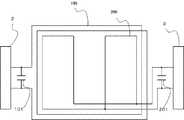
図2に示されるように、本発明のリーダライタのループアンテナは送信用ループアンテナ100と受信用ループアンテナ200により構成される。 As shown in FIG. 2, the loop antenna of the reader / writer according to the present invention includes a
送信用ループアンテナ100は送信回路2と接続されており、送信回路2から送られてきたキャリア周波数が輻射する。また送信用ループアンテナ100は、コンデンサ101が並列に接続され、共振回路を構成している。この共振回路の共振周波数はキャリア発生器21から印加される周波数と同一周波数もしくはその周辺周波数に設定する。送信用ループアンテナ100は2ターンのプリント板配線で同一基板上に構成されており、送信用ループアンテナ100のループの形状は長方形となっている。 The
受信用ループアンテナ200は、受信回路3に接続されており、ICカードから情報を受け取り、そして受信回路3に流す。さらにコンデンサ201が並列に接続されており共振回路を構成している。ここで設定される共振周波数は上述したアンテナ100の共振周波数(キャリア周波数またはキャリア周波数の近傍周波数)に対して数MHz単位で高い方向にずれた周波数である。この周波数により、送信用の共振周波数に影響されること無く受信特性を得る事が可能である。 The
また受信用ループアンテナ200は送信用ループアンテナ100の内側に配置され、さらに受信用ループアンテナ200自体で送信用ループアンテナ100の長方形ループ内を小さな長方形のループで3分割に分けるよう一筆書きで1ターンのプリント板配線で並列回路を同一基板上に構成している。 The
そして全てのアンテナの巻き方向は同一である。 And the winding direction of all the antennas is the same.
また、全てのアンテナ及びコイルは互いに相互誘導の効果を及ぼす範囲内で構成されている。 Moreover, all the antennas and coils are configured within a range in which mutual effects are exerted.
この実施例を行うことにより、さまざまな共振周波数をもったICカードの通信性能を向上させることができる。なおアンテナの共振周波数はこのアンテナに接続されたコンデンサ101または201の要領により一意に決定する。 By performing this embodiment, it is possible to improve the communication performance of an IC card having various resonance frequencies. The resonance frequency of the antenna is uniquely determined by the procedure of the
図3には本発明の実施例2にかかる無線送受信装置の構成を示す。この実施例2の各構成要素について、図1の実施例1の無線送受信装置の各部と同一部分は同一符号で示す。この実施例2が実施例1と異なる点は、ループアンテナ1001の構成である。 FIG. 3 shows a configuration of a wireless transmission / reception apparatus according to the second embodiment of the present invention. About each component of this Example 2, the same part as each part of the radio | wireless transmitter / receiver of Example 1 of FIG. 1 is shown with the same code | symbol. The difference between the second embodiment and the first embodiment is the configuration of the
図4に示されるように、本発明のリーダライタンテナは7つのループコイルにより構成される。 As shown in FIG. 4, the reader / writer tenter of the present invention is composed of seven loop coils.
送信用ループアンテナ300は、送信回路2に接続されており、送信回路2からおくられてきたキャリア周波数を輻射する。送信用ループアンテナ300は1ターンのプリント板配線で同一基板上に構成されており、送信用ループアンテナ300によって全てのアンテナの囲む構成となっている。また送信用ループアンテナ300のループの形状は長方形に巻かれている。送信用ループアンテナ300は、送信用コンデンサ301が並列に接続されており共振回路を構成している。 The transmission loop antenna 300 is connected to the
第1の自己共振ループコイル400は送信用ループアンテナ300の内側に配置され、送信用ループアンテナ300から輻射される磁界を受け相互誘導によりさらに磁界の輻射を行うことにより送信回路2で制限されている電源出力を一定にしたまま磁界をより強く輻射する事が可能となる。 The first self-resonant loop coil 400 is disposed inside the transmission loop antenna 300 and is limited by the
この第1の自己共振ループコイル400は2ターンのプリント板配線で同一基板上に構成されており、コンデンサ401が直列に接続されている。共振周波数は前述のアンテナの共振周波数とは別の周波数(数MHz単位で高い値とする)に設定されている。また第1の自己共振ループコイル400のコイルのループの形状は長方形である。 The first self-resonant loop coil 400 is formed on the same substrate by two-turn printed circuit board wiring, and a capacitor 401 is connected in series. The resonance frequency is set to a frequency (high value in units of several MHz) different from the resonance frequency of the antenna described above. Further, the shape of the coil loop of the first self-resonant loop coil 400 is a rectangle.
また第1の自己共振ループコイル400は送信用ループアンテナ300と異なる共振周波数に設定されていることにより、互いのアンテナの共振周波数に影響されることがほとんどない。 In addition, since the first self-resonant loop coil 400 is set to a resonance frequency different from that of the transmission loop antenna 300, the first self-resonance loop coil 400 is hardly influenced by the resonance frequency of each antenna.
第2の自己共振ループコイル500は第1の自己共振ループコイル400の内側に配置され、送信用ループアンテナ300から輻射される磁界を受け相互誘導によりさらに磁界の輻射を行うことにより送信回路2で制限されている電源出力を一定にしたまま磁界をより強く輻射する事が可能となる。 The second self-
この第2の自己共振ループコイル500は2ターンのプリント板配線で同一基板上に構成されており、コンデンサ501が直列に接続されている。共振周波数は前述のアンテナの共振周波数とは別の周波数(数MHz単位で高い値とする)に設定されている。また第2の自己共振ループコイル500のコイルのループの形状は長方形である。 The second self-
また第2の自己共振ループコイル500は送信用ループアンテナ300と第1の自己共振ループコイル400と異なる共振周波数に設定されていることにより、互いのアンテナの共振周波数に影響されることがほとんどない。 In addition, since the second self-
受信用ループアンテナ600は、受信回路3に接続されており、ICカードから情報を受け取り、そして受信回路3に流す。さらにコンデンサ601が並列に接続されており共振回路を構成している。 The reception loop antenna 600 is connected to the
また受信用ループアンテナ600は第2の自己共振ループコイル500の内側に配置され、さらに受信用ループアンテナ600自体で第2の自己共振ループコイル500の長方形ループ内を小さな長方形のループで3分割に分けるよう一筆書きで1ターンのプリント板配線で並列回路を同一基板上に構成している。 The receiving loop antenna 600 is disposed inside the second self-
受信用ループアンテナ600の共振周波数をキャリア周波数に対して数MHz単位で高い方向にずらした周波数に設定することで、キャリア周波数の位相に影響されることがほとんど無く受信特性を得る事が可能である。 By setting the resonance frequency of the reception loop antenna 600 to a frequency shifted in the high direction in units of several MHz with respect to the carrier frequency, it is possible to obtain reception characteristics with little influence from the phase of the carrier frequency. is there.
第3の自己共振ループコイル700にはコンデンサ701が、第3の自己共振ループコイル800にはコンデンサ801が、第3の自己共振ループコイル900にはコンデンサ901が直列に接続されている。共振周波数は送信用ループアンテナ300、受信用ループアンテナ600の共振周波数とは別の周波数に設定されるものであり、第1の自己共振ループコイル400、第2の自己共振ループコイル500に近い値とする。第3の自己共振ループコイル700、800、900は第2の自己共振ループコイル500の内側に配置され、さらに第3の自己共振ループコイル700、900は受信用ループアンテナ600の内側であって、受信用ループアンテナ600が形成する2つの小さな長方形の内側に各1つずつ6ターンのプリント板配線で同一基板上に構成されている。第3の自己共振ループコイル800は受信ループアンテナ600の外側であって受信用ループアンテナ600が形成する2つの小さな長方形の間に小さな長方形のループの形で、6ターンのプリント板配線で同一基板上に構成されている。この第3の自己共振アンテナの大きさは必ずしも同一の大きさでなくて良い。 A capacitor 701 is connected to the third self-resonant loop coil 700, a capacitor 801 is connected to the third self-resonant loop coil 800, and a capacitor 901 is connected to the third self-resonant loop coil 900. The resonance frequency is set to a frequency different from the resonance frequency of the transmission loop antenna 300 and the reception loop antenna 600, and is a value close to that of the first self-resonance loop coil 400 and the second self-
なおコンデンサの容量の大きさは、601>301>501>401=701=801=901の順に大きい。 In addition, the magnitude | size of the capacity | capacitance of a capacitor | condenser is large in order of 601> 301> 501> 401 = 701 = 801 = 901.
受信用ループアンテナ600、第一の自己共振ループコイル500が輻射した磁界をさらに受けて相互誘導による磁界の輻射を行い、ICカードと通信可能距離をさらに向上することが可能となる。 The receiving loop antenna 600 and the first self-
また全てのアンテナ及びコイルはと同じ方向に巻かれており、巻き数は送信用ループアンテナ300に対して同数または多ければよい。 Further, all the antennas and coils are wound in the same direction as the winding, and the number of windings may be the same as or larger than that of the transmission loop antenna 300.
自己共振ループコイル700、800、900については巻き方向は送信用ループアンテナ300、自己共振ループコイル400及び自己共振ループコイル500と同じ方向に巻かれており、巻き数は自己共振ループコイル400よりも多いものとする。自己共振ループコイル600、700、800の巻き数は同一でなくてもよい。また図4(a)、(b)に示すように、自己共振ループコイル600、700、800の形状や大きさは必ずしも同一でなくてよい。 The self-resonant loop coils 700, 800, and 900 are wound in the same direction as the transmitting loop antenna 300, the self-resonant loop coil 400, and the self-
また、全てのアンテナ及びコイルは互いに相互誘導の効果を及ぼす範囲内で構成されている。 Moreover, all the antennas and coils are configured within a range in which mutual effects are exerted.
1 CPU
2 送信回路
3 受信回路
100、300 送信用ループアンテナ
200、600 受信用ループアンテナ
400 第1の自己共振ループコイル
500 第2の自己共振ループコイル
700、800、900 第3の自己共振ループコイル1 CPU
2 transmitting
Claims (6)
Translated fromJapaneseキャリアを印加される送信用ループアンテナと、
前記送信用ループアンテナの共振周波数とは異なる共振周波数に設定されており、前記送信用ループアンテナの同一平面上の内側に前記受信用ループアンテナのループの形状が長方形である2つのループコイルを並列に配置して構成した並列回路である受信用ループアンテナと、
を有することを特徴とするループアンテナ。A loop antenna used in a wireless transmission / reception device that performs non-contact communication with a wireless communication medium by generating electromagnetic waves,
A loop antenna for transmission to which a carrier is applied; and
A resonance frequency different from the resonance frequency of the transmission loop antenna is set, and two loop coils having a rectangular loop shape of the reception loop antenna are arranged in parallel on the same plane of the transmission loop antenna. A receiving loop antenna that is a parallel circuit arranged and
A loop antenna characterized by comprising:
キャリアを印加することにより情報を送信する送信用ループアンテナと、
前記送信用ループアンテナの同一平面上の内側に配置された第1の自己共振ループコイルと、
前記第1の自己共振ループコイルの同一平面上の内側に配置された第2の自己共振ループコイルと、
前記第2の自己共振ループコイルの同一平面上の内側に配置されたそれぞれ形状の異なる複数の第3の自己共振ループコイルと、
前記第3の自己共振ループコイルのいずれか2つの自己共振ループコイルの外側に巻回して配置した、無線通信媒体より送られてきた情報を受信し受信回路に送る受信用ループアンテナと、
を有することを特徴とするループアンテナ。A loop antenna used in a wireless communication device that performs non-contact communication with a wireless communication medium by generating electromagnetic waves,
A transmission loop antenna for transmitting information by applying a carrier;
A first self-resonant loop coil disposed inside the same plane of the transmitting loop antenna;
A second self-resonant loop coil disposed within the same plane of the first self-resonant loop coil;
A plurality of third self-resonant loop coils each having a different shape, disposed on the same plane inside the second self-resonant loop coil;
A receiving loop antenna for receiving information sent from a wireless communication medium, wound around the outside of any two self-resonant loop coils of the third self-resonant loop coil, and sending the information to a receiving circuit;
A loop antenna characterized by comprising:
キャリアを印加される送信用ループアンテナと、
前記送信用ループアンテナの共振周波数とは異なる共振周波数に設定されており、前記送信用ループアンテナの同一平面上の内側に前記受信用ループアンテナのループの形状が長方形である2つのループコイルを並列に配置して構成した並列回路である受信用ループアンテナと、
前記送信用ループアンテナに接続された、無線送信を行うための電気信号を出力する送信回路と、
前記受信用ループアンテナに接続され、前記受信用ループアンテナが受けた電磁波からの電気信号を受けとる受信回路と、
前記送信回路と前記受信回路を制御する中央処理装置と、
を有することを特徴とする無線送受信装置。A loop antenna used in a wireless transmission / reception device that performs non-contact communication with a wireless communication medium by generating electromagnetic waves,
A loop antenna for transmission to which a carrier is applied; and
A resonance frequency different from the resonance frequency of the transmission loop antenna is set, and two loop coils having a rectangular loop shape of the reception loop antenna are arranged in parallel on the same plane of the transmission loop antenna. A receiving loop antenna that is a parallel circuit arranged and
A transmission circuit connected to the transmission loop antenna for outputting an electric signal for wireless transmission;
A receiving circuit connected to the receiving loop antenna and receiving an electric signal from an electromagnetic wave received by the receiving loop antenna;
A central processing unit for controlling the transmitting circuit and the receiving circuit;
A wireless transmission / reception device comprising:
キャリア印加することにより情報を送信する送信用ループアンテナと、
前記送信用ループアンテナの同一平面上の内側に配置された第1の自己共振ループコイルと、
前記第1の自己共振ループコイルの同一平面上の内側に配置された第2の自己共振ループコイルと、
前記第2の自己共振ループコイルの同一平面上の内側に配置されたそれぞれ形状の異なる複数の第3の自己共振ループコイルと、
前記第3の自己共振ループコイルのいずれか2つの自己共振ループコイルの外側に巻回して配置した、無線通信媒体より送られてきた情報を受信し前記受信回路に送る受信用ループアンテナと、
前記送信用ループアンテナに接続された、無線送信を行うための電気信号を出力する送信回路と、
前記受信用ループアンテナに接続され、前記受信用ループアンテナが受けた電磁波からの電気信号を受けとる受信回路と、
前記送信回路と前記受信回路を制御する中央処理装置と、
を有することを特徴とする無線送受信装置。A loop antenna used in a wireless transmission / reception device that performs non-contact communication with a wireless communication medium by generating electromagnetic waves,
A transmission loop antenna for transmitting information by applying a carrier;
A first self-resonant loop coil disposed inside the same plane of the transmitting loop antenna;
A second self-resonant loop coil disposed within the same plane of the first self-resonant loop coil;
A plurality of third self-resonant loop coils each having a different shape, disposed on the same plane inside the second self-resonant loop coil;
A receiving loop antenna for receiving information sent from a wireless communication medium, wound around the outer side of any two self-resonant loop coils of the third self-resonant loop coil, and sending the information to the receiving circuit;
A transmission circuit connected to the transmission loop antenna for outputting an electric signal for wireless transmission;
A receiving circuit connected to the receiving loop antenna and receiving an electric signal from an electromagnetic wave received by the receiving loop antenna;
A central processing unit for controlling the transmitting circuit and the receiving circuit;
A wireless transmission / reception device comprising:
Priority Applications (1)
| Application Number | Priority Date | Filing Date | Title |
|---|---|---|---|
| JP2007014860AJP2008182528A (en) | 2007-01-25 | 2007-01-25 | Loop antenna and wireless transceiver including loop antenna |
Applications Claiming Priority (1)
| Application Number | Priority Date | Filing Date | Title |
|---|---|---|---|
| JP2007014860AJP2008182528A (en) | 2007-01-25 | 2007-01-25 | Loop antenna and wireless transceiver including loop antenna |
Publications (1)
| Publication Number | Publication Date |
|---|---|
| JP2008182528Atrue JP2008182528A (en) | 2008-08-07 |
Family
ID=39726085
Family Applications (1)
| Application Number | Title | Priority Date | Filing Date |
|---|---|---|---|
| JP2007014860APendingJP2008182528A (en) | 2007-01-25 | 2007-01-25 | Loop antenna and wireless transceiver including loop antenna |
Country Status (1)
| Country | Link |
|---|---|
| JP (1) | JP2008182528A (en) |
Cited By (2)
| Publication number | Priority date | Publication date | Assignee | Title |
|---|---|---|---|---|
| JP2008301241A (en)* | 2007-05-31 | 2008-12-11 | Toshiba Corp | Loop antenna and wireless transceiver including loop antenna |
| JP2018174704A (en)* | 2008-09-27 | 2018-11-08 | ウィトリシティ コーポレーション | Wireless energy transfer system |
Citations (12)
| Publication number | Priority date | Publication date | Assignee | Title |
|---|---|---|---|---|
| JPH06350495A (en)* | 1993-06-10 | 1994-12-22 | Omron Corp | Read/write head |
| JPH1074245A (en)* | 1996-08-30 | 1998-03-17 | Glory Ltd | Id tag reader |
| JPH1198061A (en)* | 1997-09-19 | 1999-04-09 | Toshiba Corp | Loop antenna and information processing device |
| JP2000138621A (en)* | 1998-10-30 | 2000-05-16 | Hitachi Maxell Ltd | Communication system using non-contact information medium and communication auxiliary device used in such communication system |
| JP2000174539A (en)* | 1998-12-08 | 2000-06-23 | Sony Corp | Antenna system and card-shaped storage medium |
| JP2000235628A (en)* | 1999-02-15 | 2000-08-29 | Kokusai Electric Co Ltd | Reader / writer device for non-contact IC card system and its antenna circuit |
| JP2001024548A (en)* | 1999-07-12 | 2001-01-26 | Matsushita Electric Ind Co Ltd | Mobile object identification system |
| JP2001101371A (en)* | 1999-10-04 | 2001-04-13 | Dainippon Printing Co Ltd | IC card |
| JP2001109862A (en)* | 1999-10-06 | 2001-04-20 | Toppan Printing Co Ltd | Non-contact IC card |
| JP2001109861A (en)* | 1999-10-06 | 2001-04-20 | Toppan Printing Co Ltd | Non-contact IC card |
| JP2006014281A (en)* | 2004-05-25 | 2006-01-12 | Fuji Electric Retail Systems Co Ltd | Reading device, data carrier system, and demodulation method of reading device |
| JP2006245656A (en)* | 2005-02-28 | 2006-09-14 | Toshiba Corp | Wireless communication device, wireless communication method, and non-contact IC card reader / writer device |
- 2007
- 2007-01-25JPJP2007014860Apatent/JP2008182528A/enactivePending
Patent Citations (12)
| Publication number | Priority date | Publication date | Assignee | Title |
|---|---|---|---|---|
| JPH06350495A (en)* | 1993-06-10 | 1994-12-22 | Omron Corp | Read/write head |
| JPH1074245A (en)* | 1996-08-30 | 1998-03-17 | Glory Ltd | Id tag reader |
| JPH1198061A (en)* | 1997-09-19 | 1999-04-09 | Toshiba Corp | Loop antenna and information processing device |
| JP2000138621A (en)* | 1998-10-30 | 2000-05-16 | Hitachi Maxell Ltd | Communication system using non-contact information medium and communication auxiliary device used in such communication system |
| JP2000174539A (en)* | 1998-12-08 | 2000-06-23 | Sony Corp | Antenna system and card-shaped storage medium |
| JP2000235628A (en)* | 1999-02-15 | 2000-08-29 | Kokusai Electric Co Ltd | Reader / writer device for non-contact IC card system and its antenna circuit |
| JP2001024548A (en)* | 1999-07-12 | 2001-01-26 | Matsushita Electric Ind Co Ltd | Mobile object identification system |
| JP2001101371A (en)* | 1999-10-04 | 2001-04-13 | Dainippon Printing Co Ltd | IC card |
| JP2001109862A (en)* | 1999-10-06 | 2001-04-20 | Toppan Printing Co Ltd | Non-contact IC card |
| JP2001109861A (en)* | 1999-10-06 | 2001-04-20 | Toppan Printing Co Ltd | Non-contact IC card |
| JP2006014281A (en)* | 2004-05-25 | 2006-01-12 | Fuji Electric Retail Systems Co Ltd | Reading device, data carrier system, and demodulation method of reading device |
| JP2006245656A (en)* | 2005-02-28 | 2006-09-14 | Toshiba Corp | Wireless communication device, wireless communication method, and non-contact IC card reader / writer device |
Cited By (2)
| Publication number | Priority date | Publication date | Assignee | Title |
|---|---|---|---|---|
| JP2008301241A (en)* | 2007-05-31 | 2008-12-11 | Toshiba Corp | Loop antenna and wireless transceiver including loop antenna |
| JP2018174704A (en)* | 2008-09-27 | 2018-11-08 | ウィトリシティ コーポレーション | Wireless energy transfer system |
Similar Documents
| Publication | Publication Date | Title |
|---|---|---|
| JP4232474B2 (en) | Electronic equipment with communication function | |
| JP4131250B2 (en) | Reader / writer | |
| JP4561796B2 (en) | Power receiving device and power transmission system | |
| JP4414942B2 (en) | Antenna device | |
| US9496598B2 (en) | Wireless communication system, antenna module and electronic device | |
| JP5162648B2 (en) | ANTENNA DEVICE AND COMMUNICATION DEVICE | |
| CN101243581B (en) | Antenna device | |
| US7786870B2 (en) | Transponder with an improved voltage limiter circuit | |
| TWI524596B (en) | Antenna device and communication device | |
| JPH08139516A (en) | Information processing device | |
| JP5928768B2 (en) | Non-contact communication device | |
| JP2008301241A (en) | Loop antenna and wireless transceiver including loop antenna | |
| US20120190310A1 (en) | Transceiver and radio frequency identification tag reader | |
| WO2007101992A1 (en) | A near field rf communicator and an antenna for near field rf communicators | |
| JP2000165132A (en) | Antenna device and card-like storage medium | |
| JP2009094681A (en) | Communicating system, communication apparatus, communication terminal, and antenna | |
| JP3579899B2 (en) | IC card reader / writer | |
| US20150090789A1 (en) | Calculated compensated magnetic antennas for different frequencies | |
| KR20020064451A (en) | An amplifying method for RF signals in a contactless IC card system by through a mutual induced amplifying junction antenna and an apparatus therefor | |
| JP2008182528A (en) | Loop antenna and wireless transceiver including loop antenna | |
| AU2011288921A1 (en) | Simultaneous multi-frequency RFID communication system | |
| JP3632894B2 (en) | Antenna device and card-like storage medium | |
| JP4019850B2 (en) | Non-contact IC card reader / writer communication range adjustment method | |
| JP2002353725A (en) | Electromagnetic induction antenna system | |
| JP2000067194A (en) | Storage device |
Legal Events
| Date | Code | Title | Description |
|---|---|---|---|
| A621 | Written request for application examination | Free format text:JAPANESE INTERMEDIATE CODE: A621 Effective date:20090910 | |
| A131 | Notification of reasons for refusal | Free format text:JAPANESE INTERMEDIATE CODE: A131 Effective date:20110215 | |
| A02 | Decision of refusal | Free format text:JAPANESE INTERMEDIATE CODE: A02 Effective date:20110708 |