JP2008180883A - Image forming apparatus, its print unit and supporting body of print unit - Google Patents
Image forming apparatus, its print unit and supporting body of print unitDownload PDFInfo
- Publication number
- JP2008180883A JP2008180883AJP2007013878AJP2007013878AJP2008180883AJP 2008180883 AJP2008180883 AJP 2008180883AJP 2007013878 AJP2007013878 AJP 2007013878AJP 2007013878 AJP2007013878 AJP 2007013878AJP 2008180883 AJP2008180883 AJP 2008180883A
- Authority
- JP
- Japan
- Prior art keywords
- unit
- print unit
- support
- sheet
- Prior art date
- Legal status (The legal status is an assumption and is not a legal conclusion. Google has not performed a legal analysis and makes no representation as to the accuracy of the status listed.)
- Pending
Links
- 239000000463materialSubstances0.000claimsdescription48
- 230000015572biosynthetic processEffects0.000claimsdescription31
- 238000007599dischargingMethods0.000claimsdescription6
- 238000000034methodMethods0.000description30
- 239000002699waste materialSubstances0.000description28
- 230000015654memoryEffects0.000description17
- 230000006870functionEffects0.000description13
- 238000003780insertionMethods0.000description11
- 230000037431insertionEffects0.000description11
- 239000003086colorantSubstances0.000description9
- 238000012546transferMethods0.000description7
- 238000011084recoveryMethods0.000description6
- 108091008695photoreceptorsProteins0.000description5
- 238000012545processingMethods0.000description4
- 238000010586diagramMethods0.000description3
- 230000000694effectsEffects0.000description2
- 230000005540biological transmissionEffects0.000description1
- 239000002131composite materialSubstances0.000description1
- 230000007423decreaseEffects0.000description1
- 238000003795desorptionMethods0.000description1
- 238000011161developmentMethods0.000description1
- 238000009434installationMethods0.000description1
Images


Landscapes
- Facsimiles In General (AREA)
- Printers Characterized By Their Purpose (AREA)
- Accessory Devices And Overall Control Thereof (AREA)
- Exposure Or Original Feeding In Electrophotography (AREA)
- Electrophotography Configuration And Component (AREA)
- Control Or Security For Electrophotography (AREA)
Abstract
Description
Translated fromJapanese本発明は,電子写真プロセス等を用いて画像を形成する画像形成装置およびそのプリントユニット,プリントユニットの支持体に関する。さらに詳細には,バッテリーを内蔵して携行可能であり画像形成機能を有するプリントユニットと,そのプリントユニットに消耗材を補給する機能を有する支持体とを有する画像形成装置およびそのプリントユニット,プリントユニットの支持体に関するものである。 The present invention relates to an image forming apparatus that forms an image using an electrophotographic process or the like, a print unit thereof, and a support for the print unit. More specifically, the present invention relates to an image forming apparatus having a print unit that has a built-in battery and is portable and has an image forming function, and a support having a function of supplying a consumable material to the print unit, and the print unit and the print unit support. Is.
従来より,小型で携行可能な画像形成装置が提案されている。例えば,特許文献1には,携帯電子機器に内蔵されたインクジェット方式の携帯印刷装置が開示されている。本文献に記載の携帯印刷装置では,そのバッテリーを充電する充電装置に,インクタンクおよび廃インクタンクを備えている。そして,充電と同時にインクの補給や廃インクの排出も出来るとされている。 Conventionally, a small and portable image forming apparatus has been proposed. For example,
また,特許文献2には,携帯性に適したバッテリー駆動式の画像形成装置で,非使用時の収容性に考慮したものが開示されている。本文献に記載の装置では,縦置き式の置き台に充電装置が設けられている。画像形成装置をその置き台に収容すれば,自動的にバッテリーが充電されるとされている。 Further,
また,本出願人は,携帯用の電子写真方式の画像形成装置であって,携行状態で残り印字可能枚数を算出して表示できるものを先行出願している(特願2006−83464号)。この出願では,携行部分を納めることのできるスタンドとして,充電機能とトナー補給機能とを有するものを開示している。
しかしながら,前記のような画像形成装置のプリントユニットでは,携行性を重視するためさらなる小型化および軽量化をめざして,内部に収容される消耗材の量が減らされる方向にある。一方,収容される消耗材が少なくなれば,それだけ頻繁に補給する必要がある。そのため,さらに使い勝手のよい支持体が望まれていた。また,会社等において,複数人数がそれぞれ画像形成装置のプリントユニットを携行する場合を考慮すると,各1台のプリントユニットに対して,それぞれ支持体を用意すればかなりのスペースをとることになる。そのため,複数人数で共用できる支持体も望まれるものであった。 However, in the print unit of the image forming apparatus as described above, the amount of the consumable material accommodated in the print unit tends to be reduced in order to further reduce the size and weight in order to emphasize portability. On the other hand, if the amount of consumables to be accommodated decreases, it is necessary to replenish as often. Therefore, a more convenient support was desired. Considering the case where a plurality of people carry the print unit of the image forming apparatus in a company or the like, if a support is prepared for each print unit, a considerable space is required. Therefore, a support that can be shared by multiple people was also desired.
本発明は,前記した従来の画像形成装置およびそのプリントユニット,支持体が有する問題点を解決するためになされたものである。すなわちその課題とするところは,小型で携帯可能なプリントユニットと,それに収容される消耗材を補給する支持体と,それらを有する画像形成装置であって,支持体が省スペースなものであり,複数のユーザで共用しても使い勝手のよいものである画像形成装置およびそのプリントユニット,プリントユニットの支持体を提供することにある。 The present invention has been made to solve the above-described problems of the conventional image forming apparatus, its print unit, and support. That is, the subject is a small and portable print unit, a support for replenishing the consumable material accommodated in the print unit, and an image forming apparatus having them. It is an object of the present invention to provide an image forming apparatus, a print unit thereof, and a support for the print unit that are easy to use even if they are shared by other users.
この課題の解決を目的としてなされた本発明の画像形成装置は,プリントユニットと,プリントユニットを着脱可能に支持する支持体とを有する画像形成装置であって,プリントユニットが,画像形成に用いる消耗材を収納する消耗材収納部と,バッテリーと,シート受け入れ口と,バッテリーからの電力供給により,消耗材収納部に収納されている消耗材を用いて,シート受け入れ口から受け入れたシート上に画像を形成する画像形成部と,画像形成済みのシートを排出するシート排出口とを有し,支持体が,消耗材収納部へ補給する消耗材を貯蔵する貯蔵部と,バッテリーを充電する充電装置と,プリントユニットを装着した状態でシート受け入れ口と対面し,画像形成前のシートを排出するシート受け渡し口とを有し,プリントユニットを支持体に装着しない状態では,プリントユニット単体で画像形成を行い,プリントユニットを支持体に装着した状態では,支持体からプリントユニットへの充電および消耗材の供給を行うとともに,シート受け渡し口からシート受け入れ口に送り込まれたシートに画像形成を行うものである。 An image forming apparatus of the present invention made for the purpose of solving this problem is an image forming apparatus having a print unit and a support that removably supports the print unit, and the print unit stores a consumable material used for image formation. An image is formed on the sheet received from the sheet receiving port using the consumable material stored in the consumable material storing unit by supplying power from the battery, the battery, the sheet receiving port, and the power supply from the battery. An image forming unit, a sheet discharge port for discharging an image-formed sheet, and a support for storing a consumable material to be supplied to the consumable material storage unit, a charging device for charging a battery, and a print unit With a sheet receiving port facing the sheet receiving port and discharging a sheet before image formation. When the print unit is not mounted on the support, image formation is performed by the print unit alone. When the print unit is mounted on the support, charging and supply of consumables are performed from the support to the print unit, and the sheet receiving port is used for charging. An image is formed on the sheet fed to the sheet.
本発明の画像形成装置によれば,プリントユニットは,支持体に装着しない状態で単体で画像形成ができる。この場合は,バッテリーからの電力供給により,消耗材収納部に収納されている消耗材を用いて画像形成する。従って,外部電源等を必要としない。さらに,プリントユニットが支持体に装着された状態では,支持体側の資源をも利用して画像形成できる。従って,消耗材の欠乏やバッテリー切れにより画像形成ができなくなる懸念は低い。さらに,プリントユニットを支持体に装着すれば,支持体からプリントユニットへの充電および消耗材の供給が行われる。従って,その後にプリントユニットを支持体から外して,単体で画像形成しても,消耗材がすぐに欠乏するということはない。なお,ここでの資源とは,電力と消耗材とを含むものである。また,消耗材とは,主としてトナーやインク等の色材のことである。 According to the image forming apparatus of the present invention, the print unit can form an image alone without being attached to the support. In this case, an image is formed using the consumable material stored in the consumable material storage unit by supplying power from the battery. Therefore, no external power source is required. Further, when the print unit is mounted on the support, it is possible to form an image using resources on the support. Therefore, there is little concern that image formation will not be possible due to lack of consumables or battery exhaustion. Further, when the print unit is mounted on the support, charging and supply of consumable materials are performed from the support to the print unit. Therefore, even if the print unit is subsequently removed from the support and an image is formed alone, the consumable material is not immediately depleted. Here, the resources include power and consumable materials. Further, the consumable material is mainly a color material such as toner or ink.
さらに本発明では,プリントユニットは,支持体に装着されているか否かを検知する装着センサを有することが望ましい。このようにすれば,装着センサの結果に基づいて,支持体に装着されたことが認識される。 Furthermore, in the present invention, it is desirable that the print unit has a mounting sensor for detecting whether or not the printing unit is mounted on the support. If it does in this way, it will be recognized that it was equipped with a support based on a result of a wearing sensor.
さらに本発明では,支持体は,画像形成前のシートを貯蔵するシート貯蔵部と,シート貯蔵部からシート受け渡し口へシートを搬送する給紙部とを有することが望ましい。このようにすれば,支持体に装着された状態では,シートを手差しする必要がない。 Furthermore, in the present invention, it is preferable that the support has a sheet storage unit that stores a sheet before image formation, and a sheet feeding unit that conveys the sheet from the sheet storage unit to the sheet delivery port. In this way, it is not necessary to manually feed the sheet when it is mounted on the support.
さらに本発明では,支持体は,原稿の画像を読み取るスキャナを有することが望ましい。スキャナで読み取った画像データに基づいて画像形成することにより,コピー処理を行うことができる。 Furthermore, in the present invention, it is desirable that the support has a scanner that reads an image of a document. Copy processing can be performed by forming an image based on image data read by a scanner.
さらに本発明では,支持体は,開閉可能なカバー部を上部に有し,プリントユニットを装着してカバー部を閉じた状態では,プリントユニットの上面にカバー部の下面が接し,カバー部を開いた状態でプリントユニットを上下方向に移動させることにより,支持体とプリントユニットとの脱着を行うことが望ましい。このようになっていれば,プリントユニットの脱着は容易である。 Furthermore, in the present invention, the support has an openable / closable cover at the top, and when the print unit is mounted and the cover is closed, the bottom of the cover is in contact with the top of the print unit and the cover is open. It is desirable to attach and detach the support and the print unit by moving the print unit up and down. If this is the case, the print unit can be easily attached and detached.
さらに本発明では,カバー部は,原稿の画像を読み取るスキャナを有することが望ましい。このようにすれば,原稿の画像を読み取って,その画像に基づいてプリントさせることができる。 Furthermore, in the present invention, it is desirable that the cover unit has a scanner that reads an image of a document. In this way, it is possible to read an image of a document and print based on the image.
また,本発明の画像形成装置は,プリントユニットと,プリントユニットを着脱可能に支持する支持体とを有する画像形成装置であって,プリントユニットが,画像形成に用いる消耗材を収納する消耗材収納部と,バッテリーと,シート受け入れ口と,バッテリーからの電力供給により,消耗材収納部に収納されている消耗材を用いて,シート受け入れ口から受け入れたシート上に画像を形成する画像形成部と,画像形成済みのシートを排出するシート排出口とを有し,支持体が,消耗材収納部へ補給する消耗材を貯蔵する貯蔵部と,バッテリーを充電する充電装置とを有し,プリントユニットおよび支持体がそれぞれ,補給動作を許容するか否かを決定するための個別情報を記憶する個別情報記憶部を有し,プリントユニットと支持体との一方が,装着した相手方の個別情報記憶部に記憶されている個別情報を読み出す読み出し部と,読み出した個別情報と自己の個別情報記憶部に記憶されている個別情報との対比により,装着した相手方を認証する認証部とを有し,プリントユニットを支持体に装着しない状態では,プリントユニット単体で画像形成を行い,プリントユニットを支持体に装着した状態では,認証部による認証がなされた場合に限り,支持体からプリントユニットへの充電および消耗材の供給を行うものであってもよい。 An image forming apparatus according to the present invention is an image forming apparatus having a print unit and a support that removably supports the print unit, and the print unit stores a consumable material storage unit that stores consumable materials used for image formation; A battery, a sheet receiving port, an image forming unit that forms an image on the sheet received from the sheet receiving port using the consumable material stored in the consumable material storing unit by supplying power from the battery; A sheet discharge port for discharging a used sheet, and the support includes a storage unit for storing consumable materials to be supplied to the consumable material storage unit, and a charging device for charging the battery. Each has an individual information storage unit for storing individual information for determining whether or not replenishment operation is permitted. The other party who wears it by comparing the read-out unit that reads out the individual information stored in the individual information storage unit of the other party with the comparison between the read-out individual information and the individual information stored in its own individual information storage unit An authentication unit that authenticates the image, and when the print unit is not mounted on the support, image formation is performed by the print unit alone, and when the print unit is mounted on the support, it is supported only when authentication is performed by the authentication unit. Charging from the body to the printing unit and supply of consumables may be performed.
本発明の画像形成装置によれば,プリントユニットは,支持体に装着しない状態で単体で画像形成ができる。さらに本発明では,プリントユニットと支持体とがそれぞれ,装着した相手方を認証することができる。そして,その認証がなされた場合に限り,支持体からプリントユニットへの充電および消耗材の供給が行われる。すなわち,認証がなされなかった場合は当然,充電および消耗材の供給が行われない。従って,供給先となるプリンタユニットを制限することができる。 According to the image forming apparatus of the present invention, the print unit can form an image alone without being attached to the support. Furthermore, according to the present invention, the print unit and the support can respectively authenticate the other party wearing the print unit and the support. Only when the authentication is made, charging from the support to the print unit and supply of consumables are performed. That is, if authentication is not performed, naturally, charging and supply of consumable materials are not performed. Accordingly, it is possible to limit the printer unit as the supply destination.
さらに本発明では,プリントユニットおよび支持体の個別情報記憶部は,複数の個別情報を記憶するものであることが望ましい。このようなものであれば,供給先として許容される相手方として,複数の相手を記憶することができる。 Further, in the present invention, it is desirable that the individual information storage unit of the print unit and the support body is to store a plurality of individual information. If this is the case, a plurality of opponents can be stored as counterparties allowed as the supply destination.
さらに本発明では,プリントユニットおよび支持体がそれぞれ,読み出し部と,認証部とを有し,プリントユニットを支持体に装着した状態では,双方の認証部による認証がともになされた場合に限り,支持体からプリントユニットへの充電および消耗材の供給を行うことが望ましい。このようにすれば,不正な認証が行われることが確実に防止される。 Furthermore, in the present invention, each of the print unit and the support has a reading unit and an authentication unit. When the print unit is mounted on the support, only the authentication by both authentication units is performed. It is desirable to charge the print unit and supply consumables. In this way, unauthorized authentication is reliably prevented.
また,本発明は,画像形成機能を有するプリントユニットを着脱可能に支持するプリントユニットの支持体であって,プリントユニットへ補給する消耗材を貯蔵する貯蔵部と,プリントユニットを充電する充電装置と,プリントユニットを装着した状態でそのシート受け入れ口と対面し,画像形成前のシートを排出するシート受け渡し口とを有し,プリントユニットを装着した状態では,プリントユニットへの充電および消耗材の供給を行うとともに,シート受け渡し口からプリントユニットのシート受け入れ口にシートを送り込むプリントユニットの支持体にも及ぶ。 The present invention also provides a print unit support for detachably supporting a print unit having an image forming function, the storage unit storing consumables to be supplied to the print unit, a charging device for charging the print unit, and the print unit. In this state, the sheet receiving port faces the sheet receiving port and discharges a sheet before image formation. When the print unit is mounted, the print unit is charged and consumables are supplied and the sheet transferring port is It extends to the support of the print unit that feeds the sheet from the sheet to the sheet receiving port of the print unit.
さらに本発明のプリントユニットの支持体では,画像形成前のシートを貯蔵するシート貯蔵部と,シート貯蔵部からシート受け渡し口へシートを搬送する給紙部とを有することが望ましい。 Furthermore, it is preferable that the print unit support of the present invention includes a sheet storage unit that stores a sheet before image formation and a sheet feeding unit that conveys the sheet from the sheet storage unit to the sheet delivery port.
また,本発明は,支持体に着脱可能に支持されるプリントユニットであって,画像形成に用いる消耗材を収納する消耗材収納部と,バッテリーと,シート受け入れ口と,バッテリーからの電力供給により,消耗材収納部に収納されている消耗材を用いて,シート受け入れ口から受け入れたシート上に画像を形成する画像形成部と,画像形成済みのシートを排出するシート排出口と,補給動作を許容するか否かを決定するための個別情報を記憶する個別情報記憶部と,支持体に装着された時にその支持体の個別情報を読み出す読み出し部と,読み出した個別情報と自己の個別情報記憶部に記憶されている個別情報との対比により,装着された支持体を認証する認証部とを有し,支持体に装着されない状態では,単体で画像形成を行い,支持体に装着された状態では,認証部による認証がなされた場合に限り,その支持体からの充電および消耗材の供給を受けるプリントユニットにも及ぶ。 Further, the present invention is a print unit that is detachably supported on a support, and includes a consumable material storage unit that stores consumable materials used for image formation, a battery, a sheet receiving port, and a power supply from the battery. Using the consumables stored in the consumable storage unit, the image forming unit that forms an image on the sheet received from the sheet receiving port, the sheet discharge port that discharges the image-formed sheet, and the replenishment operation are allowed. An individual information storage unit for storing individual information for determining whether or not to perform the reading, a reading unit for reading the individual information of the support when mounted on the support, and the read individual information and its own individual information storage unit An authentication unit that authenticates the mounted support by comparison with the individual information stored in the image, and when not mounted on the support, it forms an image on its own and The wearing state, only when the authentication by the authentication unit is made extends to the print unit receiving supply of charging and consumable from its support.
また,本発明は,画像形成機能を有するプリントユニットを着脱可能に支持するプリントユニットの支持体であって,プリントユニットへ補給する消耗材を貯蔵する貯蔵部と,プリントユニットを充電する充電装置と,補給動作を許容するか否かを決定するための個別情報を記憶する個別情報記憶部と,プリントユニットを装着した時にそのプリントユニットの個別情報を読み出す読み出し部と,読み出した個別情報と自己の個別情報記憶部に記憶されている個別情報との対比により,装着したプリントユニットを認証する認証部とを有し,プリントユニットを装着した状態では,認証部による認証がなされた場合に限り,そのプリントユニットへの充電および消耗材の供給を行うプリントユニットの支持体にも及ぶ。 The present invention also provides a print unit support that removably supports a print unit having an image forming function, a storage unit that stores consumables to be supplied to the print unit, a charging device that charges the print unit, and a supply operation. An individual information storage unit for storing individual information for determining whether or not to permit, a reading unit for reading out the individual information of the print unit when the print unit is mounted, and storing the read individual information and its own individual information storage unit The authentication unit authenticates the installed print unit by comparison with the individual information that has been installed. When the print unit is installed, charging of the print unit and the consumption of consumables are only possible if the authentication unit authenticates. It also extends to the support of the print unit that supplies it.
本発明の画像形成装置およびそのプリントユニット,プリントユニットの支持体によれば,小型で携帯可能なプリントユニットと,それに収容される消耗材を補給する支持体と,それらを有する画像形成装置であって,支持体が省スペースなものであり,複数のユーザで共用しても使い勝手のよいものである。 According to the image forming apparatus and the print unit of the present invention, and the support for the print unit, a small and portable print unit, a support for replenishing the consumable material accommodated therein, and an image forming apparatus having them, The body is space-saving, and it is easy to use even if it is shared by multiple users.
「第1の形態」
以下,本発明を具体化した第1の形態について,添付図面を参照しつつ詳細に説明する。本形態は,電子写真方式の画像形成装置であって,画像形成機能を備えるプリントユニットと,そのプリントユニットに補給されるトナー等の消耗材を貯蔵するタンクユニットとを有するものに本発明を適用したものである。本形態では,タンクユニット20が支持体に相当する。"First form"
Hereinafter, a first embodiment of the present invention will be described in detail with reference to the accompanying drawings. The present embodiment is an electrophotographic image forming apparatus in which the present invention is applied to a print unit having an image forming function and a tank unit for storing a consumable material such as toner supplied to the print unit. It is. In this embodiment, the
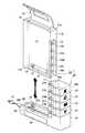
本形態に係る画像形成装置1は,図1に示すように,プリントユニット10とタンクユニット20とを有している。これらは,図2に示すように,互いに図中上下方向にずらすことにより,着脱可能にされている。プリントユニット10は,画像形成機能を備えている。タンクユニット20は,プリントユニット10で使用されるトナー等の消耗材を貯蔵するタンクであるとともに,プリントユニット10への充電機能を有している。なおここでは,このプリントユニット10とタンクユニット20とは1対1のセットで販売されるものとする。ただし,後述するように,単品販売されることもあり得る。 As shown in FIG. 1, the
プリントユニット10は,図1に示すように,画像形成機能を内蔵する本体部11を有する。本体部11は略直方体形状であり,図中上側に示されている上面11aには排紙口12および排紙トレイ13が設けられている。排紙口12がシート排出口に相当する。排紙トレイ13は,湾曲した板状部材の中央部に孔が形成された四角枠形状であり,タンクユニット20からプリントユニット10を取り外した際や着脱操作の際には,持ち手として利用できる。 As shown in FIG. 1, the
また,図2に示すように,プリントユニット10の本体部11の右面11bにはトナー補給部15が設けられている。トナー補給部15には,各色のトナー収納部に対応する4つの補給口15Y,15M,15C,15K,および廃トナー収納部に対応する返却口15Hが一列に並んで形成されている。このトナー補給部15は,本体部11の右面11bよりややへこんだ位置に配置されている。また,本体部11の下面11cよりの内部にはバッテリー16が配置されている。さらに,バッテリー16に並んでそのバッテリー16を充電するための充電端子17が形成されている。また,本体部11の下面11cには,バッテリー16と並んで給紙口18が形成されている。この給紙口18が,シート受け入れ口に相当する。 Further, as shown in FIG. 2, a
また,タンクユニット20は,図1に示すように,本体部11の右面11bを覆う部分(右辺部20b)と下面11cを覆う部分(下辺部20c)とを有する略L字形状をなしている。右辺部20bには,各色のトナー収納部が配置されており,その内部はY色トナー収納部21,M色トナー収納部22,C色トナー収納部23,K色トナー収納部24,および一番下段の廃トナー貯蔵部25に分割されている。ここで,各色のトナー収納部21〜24が貯蔵部に,廃トナー貯蔵部25が廃消耗材貯蔵部にそれぞれ相当している。また,下辺部20cの手前面20dには,シートを挿入するための給紙ガイド26が設けられている。 Further, as shown in FIG. 1, the
さらに,タンクユニット20には,図2に示すように,右辺部20bの図中左奥側の左内面20eには,トナー供給部27が形成されている。トナー供給部27は,本体部11のトナー補給部15と脱着される。トナー供給部27には,各色のトナー収納部21〜24に対応する4つの供給口27Y,27M,27C,27K,および廃トナー貯蔵部25に対応する回収口27Hが形成されている。トナー供給部27は,右辺部20bの左内面20eからやや突出して形成されており,トナー補給部15のへこみ内部にちょうど嵌るようになっている。また,供給口27Y,27M,27C,27Kや回収口27Hがそれぞれ,本体部11の各補給口15Y,15M,15C,15Kや返却口15Hと対応する位置に設けられている。これにより,プリントユニット10にタンクユニット20が取り付けられた際には,それぞれが対面する配置となっている。 Further, in the
また,図2に示すように,タンクユニット20の下辺部20cの図中上側の上内面20fには,凹部28が形成されている。この中に,プリントユニット10の下面11cが嵌るようになっている。この凹部28内には,電力供給部29が図中上方へ突出している。また,凹部28内に開口するガイド口30も形成されている。プリントユニット10が装着された状態では,電力供給部29はプリントユニット10の充電端子17と接続されて,プリントユニット10のバッテリー16を充電する充電装置である。 Further, as shown in FIG. 2, a
また,プリントユニット10が装着された状態では,タンクユニット20のガイド口30はプリントユニット10の給紙口18と対面されるように配置されている。このガイド口30は曲面形状を介して給紙ガイド26と連通されている。給紙ガイド26から挿入されたシートは,ガイド口30から給紙口18へ送り込まれる。なお,このタンクユニット20には電源プラグ37が接続され,家庭用電源等から電力を得られるようになっている。 When the
次に,このプリントユニット10とタンクユニット20とが装着された状態の各部分の断面を図3と図4とに示す。図3は,プリントユニット10の充電端子17とタンクユニット20の電力供給部29とが接続される部分である。これらは,はめ込むことによって接続されるようになっている。なお,ここでは単純な四角形で示しているが,適宜凸部と凹部等を形成しておくことにより,はめ込まれる向きの間違いを防止したり,機種の区別等ができるようにしてもよい。また,プリントユニット10が装着された状態では,ガイド口30が給紙口18に連通される。 Next, FIGS. 3 and 4 show cross sections of the respective portions in a state where the
さらに,電力供給部29の側面にはICチップ31が埋め込まれている。一方,プリントユニット10の充電端子17の側面には,接続部32が設けられている。プリントユニット10がタンクユニット20に正しく装着されると,接続部32とICチップ31とが対面される。これにより,プリントユニット10の制御部33(図7参照)は,接続部32を介して,ICチップ31と通信可能になる。そして,プリントユニット10の制御部33はICチップ31の内容を読み出し,あるいはICチップ31に情報を書き込むことができる。このことから,接続部32は,プリントユニット10がタンクユニット20に装着されているか否かを検知する装着センサとしても機能する。 Further, an
また,図4に示しているのは,プリントユニット10のトナー補給部15とタンクユニット20のトナー供給部27との接続部分である。図1中水平面に平行な面による断面を図1中上方から見た様子を示している。トナー供給部27の各供給口27Y(M,C,K)には開閉蓋35が取り付けられている。トナー補給部15の各補給口15Y(M,C,K)には補給路36が設けられている。プリントユニット10がタンクユニット20に装着されると,開閉蓋35が開放され,トナー供給部27とトナー補給部15とが連通される。そして,プリントユニット10がタンクユニット20から外されると,開閉蓋35は閉止される。 FIG. 4 shows a connection portion between the
次に,プリントユニット10の画像形成部の構成について,図5を参照して説明する。この図は,本体部11を図2中右方から見た断面図である。図5中下部には,バッテリー16が配置されている。図中中央部を下から上へ抜ける矢印は,シート搬送路Pを示している。シート搬送路Pの図中左側に直接転写ベルト41が巻き掛けられている。そして,シート搬送路Pに沿って直接転写ベルト41の反対側には,下から順に,Y色用画像形成部42,M色用画像形成部43,C色用画像形成部44,K色用画像形成部45が配置されている。それらのさらに上方には,定着部46が配置されている。また,各色の画像形成部42〜45より下方で,バッテリー16のやや上方の位置に,廃トナーボトル47が配置されている。 Next, the configuration of the image forming unit of the
各色用の画像形成部42〜45は,いずれも同じ構成であるので,同じ符号を付して簡単に説明する。感光体51を中心に,その図中右下方に現像部52,図中上方にトナー回収部53がそれぞれ配置されている。また,シート搬送路Pを挟んで感光体51と反対側には,転写装置54が配置されている。各現像部52には,それぞれの色のトナーが収容される。 Since the
次に,プリントユニット10におけるトナーの流通経路を図6に示す。この図は,本体部11を図2中左手前側から見た断面図である。図中太い破線の矢印は新しいトナーの流れであり,細い破線の矢印は廃トナーの流れである。例えばY色については,補給口15Yから補給されたトナーは,Y色用の現像部52に収容される。そして,現像部52から感光体51へ供給されて,画像形成に使用される。転写後も感光体51の上に残留して廃トナーとなったものは,トナー回収部53を介して細い破線の矢印に沿って回収され,廃トナーボトル47に収容される。 Next, a toner distribution path in the
本形態の画像形成装置1では,タンクユニット20に装着されていない状態では,プリントユニット10の単体で画像形成を行う。この場合は,バッテリー16に蓄えられている電力を利用し,各色の現像部52に収容されているトナーを使用して,給紙口18から手動で差し込まれたシートに画像が形成される。差し込まれたシートは,シート搬送路Pに沿って,図5中下から上向きに搬送される。その途中において,各色用の画像形成部42〜45によって,各感光体51上にそれぞれの色のトナー像が形成される。 In the
形成されたトナー像は,転写装置54によってシートに転写され,シート上で重ね合わされる。さらに,定着部46によってシートにトナー像が定着される。こうして画像が形成されたシートは,図中上方の排紙口12から排出される。転写後も感光体51に残ったトナーはトナー回収部53によって回収される。なお,プリントユニット10の単体で画像形成を行う場合には,プリントユニット10を寝かせて行ってもよい。 The formed toner image is transferred onto the sheet by the
ここで,プリントユニット10の単体で画像形成を行う場合には,現像部52に収容されているトナーのみが使用できる。プリントユニット10の小型化のために,この収容量はあまり多くない。そのため,画像形成を繰り返して,各色の現像部52内に収容されているトナーを多く消費した場合には,トナーが無くなることもある。また,画像形成に伴い,廃トナーボトル47には,次第に廃トナーが蓄積される。いずれかの色のトナーが無くなるかまたは廃トナーボトル47が満杯となった場合には,そのままでは正常な画像が形成できない。 Here, when the image is formed by the
そこで,このプリントユニット10では,トナーが無くなるかあるいは廃トナーボトル47が満杯となる前にバッテリー切れとなるように,バッテリー16の容量が選択されている。バッテリー16の残量はアイコン等によって常時表示されているので,ユーザはそれにより継続して印字可能かどうかをある程度判断できる。またあるいは,プリントユニット10が,その単体によって印字可能な残り枚数を算出し,表示するようにしてもよい。 Therefore, in this
また,本形態の画像形成装置1では,プリントユニット10をタンクユニット20に装着した状態で画像形成を行うこともできる。その場合には,図1に示した給紙ガイド26からシートを差し込む。差し込まれたシートは,ガイド口30からプリントユニット10の給紙口18に送り込まれる。そして,プリントユニット10単体の場合と同様に,シートに画像が形成される。 In the
この場合,タンクユニット20に給紙ガイド26が設けられているので,図示のようにプリントユニット10を縦置きにしたまま画像形成する場合でも,シートは水平に差し込めばよい。例えば,テーブル等に沿って差し込むことができるので,シートの供給は容易である。このため,プリントユニット10を縦置きに設置でき,省スペース化が可能である。また,給紙ガイド26部分をさらに改良して,例えば自動給紙用の装置を装着できるようにすることもできる。その場合には,種々のサイズの自動給紙カセットを装備できる拡張性を有している。 In this case, since the
ただし,この場合では,電源プラグ37を介して家庭用電源等の電力も利用できる。また,各色の現像部52に収容されているトナーが少なくなったら,タンクユニット20のトナー供給部27からの補給を受けることができる。あるいは,消費した分だけ直ちに補給させてもよい。このようにすれば,実質的にタンクユニット20のトナーを使用して画像形成を行っていることとなる。また,廃トナーについても同様に,廃トナーボトル47に溜めることなく,即座にタンクユニット20に回収させてもよい。 In this case, however, electric power from a household power source can be used via the
本形態では,プリントユニット10のバッテリー16の充電やトナーの補給が必要となると,ユーザは適宜プリントユニット10をタンクユニット20に装着する。タンクユニット20に装着されることによって,プリントユニット10のバッテリー16が充電されるとともに,トナーが補給され,廃トナーが回収される。 In this embodiment, when the
ただし,本形態のプリントユニット10では,ユーザによってタンクユニット20に取り付けられると,補給動作に入る前に,タンクユニット20の認証処理を行う。すなわち,そのタンクユニット20が,そのプリントユニット10に対応しているものであるかどうかを確認する。これは,そのタンクユニット20に収容されている消耗材を,対応するプリントユニット10以外のものに補給されることを防止するためのものである。例えば,本来のユーザ以外の人が勝手にタンクユニット20を使用することが防止される。また,そのプリントユニット10に,対応するタンクユニット20に収容されているものと異なる種類の消耗材が補給されることが防止される。例えば,普通画質用のトナーと写真画質用のトナーのように,タイプの異なるトナーが混合されて補給されることが防止される。 However, in the
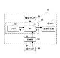
そのために,プリントユニット10は,タンクユニット20に装着されるとまず,接続部32を介してICチップ31の内容を読み出す。このプリントユニット10の制御構成を,図7を参照して説明する。プリントユニット10の制御部33は,IC57とメモリ58とを有している。そして,画像形成時には各画像形成部42〜45等を制御する。また,ICチップ31に記憶されている情報は,接続部32を介してIC57に入力される。 Therefore, when the
タンクユニット20のICチップ31には,対応するプリントユニット10のシリアルナンバーが記憶されている。また,プリントユニット10のメモリ58には,自身のシリアルナンバーが記憶されている。そこで,IC57は,ICチップ31から読み出されたシリアルナンバーとメモリ58に保存されているものとを比較し,合致していれば補給動作を開始する。合致していない場合は,警告ランプ59等によって警告表示を行うとともに,補給動作を行わない。さらに,装着された状態での画像形成も行わない。 The
次に,この認証処理について,図8のフローチャートを参照して説明する。この処理は,ユーザによって,プリントユニット10がタンクユニット20に取り付けられると,プリントユニット10の制御部33によって行われる。制御部33では,充電端子17がタンクユニット20の電力供給部29に接続されたことを感知すると,接続部32を介してICチップ31の内容を読み出す(S101)。 Next, this authentication process will be described with reference to the flowchart of FIG. This process is performed by the
そして,接続されたタンクユニット20のICチップ31から読み出したシリアルナンバーと自身のシリアルナンバーとを比較する(S102)。これらが一致していない場合は(S102:No),認証失敗である。この場合には,バッテリー16の充電やトナーの補給は行われない(S103)。さらに,認証失敗により補給処理が行われなかったことを表示して,この処理を終了する。 Then, the serial number read from the
あるいは,読み出されたシリアルナンバーが,自身のシリアルナンバーと一致していた場合(S102:Yes)には,認証成功である。この場合は,プリントユニット10はそのタンクユニット20からの消耗材の補給を受けることができる(S104)。そこで,バッテリー16は電力供給部29から電力の供給を受けて,充電される。また,各色のトナー補給部15はトナー供給部27とそれぞれ連通され,各色のトナー収納部21〜24から各色の現像部52へとトナーが補給される。また,廃トナーボトル47に収容されている廃トナーは,返却口15Hからタンクユニット20の回収口27Hを介して,廃トナー貯蔵部25に回収される。 Alternatively, if the read serial number matches its own serial number (S102: Yes), authentication is successful. In this case, the
プリントユニット10では,これらすべての補給動作が完了するまで補給動作を続ける(S105)。すべての補給動作が終了したら(S105:Yes),終了したことを表示して(S106),この処理を終了する。なおここでは,プリントユニット10によって認証処理が行われるとしたが,タンクユニット20側で行うこともできる。またあるいは,両方で行うようにすることもできる。 The
以上は,プリントユニット10とタンクユニット20とが1対1に備えられている場合について説明した。これに対し,複数のメンバーで構成されるグループにおいてタンクユニット20を共用する場合もある。すなわち,プリントユニット10のみが買い足しされた場合である。このような場合には,タンクユニット20のICチップ31に,対応する複数のプリントユニット10のシリアルナンバーをすべて記憶させればよい。この記憶させる処理は,権限を有する管理者等によって別途行われる。そして,プリントユニット10とタンクユニット20とが装着された時には,プリントユニット10の制御部33は,タンクユニット20に記憶されている複数のシリアルナンバーに自身のナンバーが含まれていることを確認してから,補給動作を行う。 The case where the
このようにすれば,各メンバーは外出先等でそれぞれプリントユニット10を使用し,手軽に画像を形成することができる。さらに,バッテリーやトナーを補給するときには,グループのタンクユニット20に差し込むだけでよい。そのグループで保有するすべてのプリントユニット10のシリアルナンバーを,タンクユニット20のICチップ31に記憶させておけば,各メンバーは自由に補給できるとともに,部外者はタンクユニット20を勝手に使用することはできない。また,プリントユニット10が1台でタンクユニット20が複数台ということもあり得る。その場合は,各タンクユニット20のICチップ31にいずれも,プリントユニット10のシリアルナンバーを同じように記憶させておけばよい。 In this way, each member can easily form an image by using the
また,さらにメンバーが多くなると,図9に示すように,プリントユニット10とタンクユニット20とがいずれも複数台備えられる場合もある。このような場合でも,各タンクユニット20のICチップ31に,対応する複数のプリントユニット10のシリアルナンバーをすべて記憶させればよい。あるいは,各タンクユニット20ごとに,収容されているトナーの種類を変えている場合では,同種のトナーを使用しているプリントユニット10のシリアルナンバーのみを記憶させておけばよい。 As the number of members further increases, as shown in FIG. 9, there may be a case where a plurality of
以上詳細に説明したように本形態のプリントユニット10とタンクユニット20とを有する画像形成装置1によれば,プリントユニット10をタンクユニット20に差し込むだけで,ICチップ31の内容が読み出される。そして,ICチップ31にプリントユニット10のシリアルナンバーが記憶されていれば,そのプリントユニット10はタンクユニット20によって消耗材の補給を受けることができる。従って,部外者が許可無くタンクユニット20を使用することはできない。また,誤ってよそのタンクユニット20から補給を受けてしまうこともない。従って,小型で携帯可能な本体(プリントユニット10)とその本体内に収容される消耗材を本体に対して補給する装置(タンクユニット20)とを有する画像形成装置1であって,タンクユニット20が省スペースなものであるとともに,複数のユーザで共用しても使い勝手のよいものとなっている。 As described in detail above, according to the
「第2の形態」
以下,本発明を具体化した第2の形態について,添付図面を参照しつつ詳細に説明する。本形態は,第1の形態に比較して,タンクユニットに代えて制御装置を含むボディ装置を有するものに本発明を適用したものである。本形態では,ボディ装置60が支持体に相当する。"Second form"
Hereinafter, a second embodiment of the present invention will be described in detail with reference to the accompanying drawings. In this embodiment, the present invention is applied to a device having a body device including a control device in place of the tank unit, as compared with the first embodiment. In this embodiment, the
本形態にかかるMFP装置2は,図10と図11に示すように,プリントユニット10とボディ装置60とを有している。これらの図に示しているのは,ボディ装置60にプリントユニット10を組み込んだ状態であり,この状態ではスキャン,プリント,コピー等が可能な複合プリンタとして機能できる。このうち,プリントユニット10の部分(図中太線で囲んで示す部分)のみが取り外し可能な部分であり,他の各装置はすべてボディ装置60として一体化されている。プリントユニット10は,第1の形態とほぼ同様のものであり,ここでは,第1の形態と同一の符号を付すとともに,説明を省略する。 The
本形態では例えば,複数のメンバーで共有される1台のボディ装置60と,各メンバーが携行できる複数台のプリントユニット10を備えた環境が想定される。各メンバーは必要に応じてプリントユニット10を携行し,画像形成を行うことができる。また,プリントユニット10に消耗材を補給する際には,プリントユニット10をボディ装置60に装着すればよい。 In this embodiment, for example, an environment including one
ボディ装置60は,図10と図11に示すように,原稿自動搬送部61,操作パネル部62,スキャナ部63,自動給紙部64,用紙トレイ65を有している。原稿自動搬送部61は,束原稿から原稿を1枚ずつ順にスキャナ部63へ送る。操作パネル部62は,ユーザへの情報や案内等を表示するとともに,ユーザによる入力を受け付ける。スキャナ部63は,原稿の画像を読み取り画像データを形成する。自動給紙部64は,画像形成用のシートを1枚ずつプリントユニット10へ搬送する。この他に,公衆電話回線に接続されればFAX送受信が可能なFAX機能をも有するものであってもよい。 As shown in FIGS. 10 and 11, the
このMFP装置2において,ボディ装置60にプリントユニット10が装着された状態で画像形成を行う場合には,図11に示すように,自動給紙部64から給紙されたシートが,給紙口18からプリントユニット10内に挿入される。そのシートは,シート搬送路Pに沿って図中右方から左向きに搬送される。その途中において,各色用の画像形成部42〜45によってそれぞれの色のトナー像が形成されるとともに順にシートに転写される。これにより,シート上で各色のトナー像が重ね合わされ,定着部46によって定着される。このようにして画像が形成されたシートは,図中左方の排紙トレイ13の上へ排出される。転写後も感光体等に残ったトナーは回収されて,廃トナーボトル47に収容される。 In this
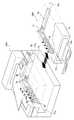
ボディ装置60からプリントユニット10を取り外すと,その部分は図10中右手前と左手前とに開口したプリンタ挿入口71(図13〜図16参照)となる。プリンタ挿入口71の図中左奥側の内壁である左内面71aには,右手前向きに突出して,トナー供給部72が形成されている。トナー供給部72には,各色のトナーをプリントユニット10に補給するための供給口73Y(M,C,K)と,廃トナーを回収するための回収口73Hが形成されている。また,プリンタ挿入口71の図中奥のコーナー付近には,電力供給部74が形成されている。さらに,プリンタ挿入口71の図中右奥側の内壁である右内面71bには,電力供給部74より図中上方に右内面71bより図中右奥向きにへこんだガイド口75が形成されている。また,電力供給部74には,接続端子76が設けられている。 When the
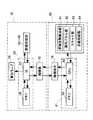
ボディ装置60にプリントユニット10が装着されると,供給口73Y(M,C,K)にプリントユニット10の各補給口15Y(M,C,K)が,回収口73Hにプリントユニット10の返却口15Hが,それぞれ対面するようになっている。また,電力供給部74にプリントユニット10の充電端子17が接続される。また,ガイド口75とプリントユニット10の給紙口18とが対面される。また,接続端子76は,プリントユニット10の充電端子17の側面に設けられた接続部32(図3参照)と接続される。これにより,図12に示すように,プリントユニット10の制御部33とボディ装置60の各部を制御する制御部81とが,通信可能になる。そして,プリントユニット10とボディ装置60との双方において,プリントユニット10とボディ装置60とが装着されたことが感知される。 When the
本形態では,ボディ装置60の制御部81は,CPU82とメモリ83とを有している。そして,原稿自動搬送部61,操作パネル部62,スキャナ部63,自動給紙部64の各部を制御する。メモリ83には,ボディ装置60自身のシリアルナンバーと,プリンタ挿入口71に取り付けられることを許可されたプリントユニット10のシリアルナンバーとが記憶されている。また,プリントユニット10の制御部33に備えられているメモリ58には,そのプリントユニット10のシリアルナンバーと,接続されるボディ装置60のシリアルナンバーとが記憶されている。 In the present embodiment, the
次に,このプリンタ挿入口71にプリントユニット10を装着する方法について説明する。ここでは,装着方向の異なる3通りの例を示す。図13に示すAタイプは,図10中右手前から左奥方向へ差し込むものである。図14に示すBタイプは,図10中左手前から右奥方向へ差し込むものである。また,図15と図16に示すCタイプは,スキャナ部63を持ち上げて,図10中上から下へ挿入するものである。これらのタイプに応じて,プリントユニット10とボディ装置60との接続箇所の形状はそれぞれ異なるが,基本的な構成はいずれも同じものである。 Next, a method for mounting the
Aタイプのボディ装置60Aでは,図13に示すように,プリントユニット10を図中矢印で示す向きに着脱する。なお本形態では,プリントユニット10を寝かせて図示しているが,第1の形態で本体部11の各面の名称として用いた上面11a,右面11b,下面11c(図2参照)を継承して用いる。すなわち,このAタイプでは,本体部11の下面11cをプリンタ挿入口71の右内面71bに沿わせて,左奥向きに挿入することにより装着される。このようになっているため,プリントユニット10の充電端子17および各補給口15Y(M,C,K)は右面11bに開口している。 In the A
Bタイプのボディ装置60Bでは,図14に示すように,プリントユニット10を図中矢印で示す向きに着脱する。すなわち,本体部11の右面11bをプリンタ挿入口71の左内面71aに沿わせて,右奥向きに挿入することにより装着される。このようになっているため,プリントユニット10の充電端子17および各補給口15Y(M,C,K)は下面11cに開口している。 In the B
Cタイプのボディ装置60Cでは,図15に示すように,プリントユニット10を図中矢印で示す向きに着脱する。本形態では,ボディ装置60の原稿自動搬送部61とスキャナ部63を合わせた部分がカバー部66となっており,図16に示すように開閉可能にされている。そして,プリントユニット10の着脱時には,カバー部66を開放してプリンタ挿入口71を露出させる。そして,プリントユニット10を装着してカバー部66を閉じた状態では,プリントユニット10の上面とカバー部66の下面とが接するように,配置されている。 In the C
すなわち,このCタイプでは,本体部11の下面11cをプリンタ挿入口71の右内面71bに,本体部11の右面11bをプリンタ挿入口71の左内面71aに,それぞれ沿わせて,下向きに挿入することにより装着される。このようになっているため,プリントユニット10の充電端子17および各補給口15Y(M,C,K)は下側の背面11dに開口している。 That is, in this C type, the
上記のいずれかによって,プリントユニット10がボディ装置60に取り付けられると,プリントユニット10の接続部32とボディ装置60の接続端子76とが接続される。すると,両方の制御部33,81は,それぞれ独立に接続相手を認証する。すなわち,プリントユニット10は接続されたボディ装置60を認証する。そして,ボディ装置60は接続されたプリントユニット10を認証する。そのために,それぞれが相手のメモリ58,83に記憶されているシリアルナンバーを読み出す。そして,その中に自分自身のシリアルナンバーが含まれているかどうかをチェックする。両方とも認証成功であった場合には,ボディ装置60からプリントユニット10への消耗材の補給を行う。補給が終了したら,そのまま画像形成可能状態となって待機する。 When the
一方,プリントユニット10とボディ装置60とのいずれか一方でも,認証が失敗した場合は,その旨を操作パネル部62に表示する。この場合には,ボディ装置60からプリントユニット10への消耗材の補給を行わないとともに,取り付けられた状態での画像形成を行わない。なお,プリントユニット10のメモリ58やボディ装置60のメモリ83に,接続を許可された相手のシリアルナンバーを記憶する手続は,権限を有する管理者によって,操作パネル部62から行われる。 On the other hand, if authentication fails in any one of the
次に,この認証処理について説明する。この処理は,ユーザによって,プリントユニット10がボディ装置60に取り付けられると,プリントユニット10の制御部33とボディ装置60の制御部81とによって並行して行われる。プリントユニット10における認証処理は,ボディ装置60のメモリ83に記憶されているシリアルナンバーのうちに,自身のシリアルナンバーがあるかどうかをチェックする処理である。この処理は第1の形態の図8で説明したものとほぼ同様である。プリントユニット10は,この認証結果をボディ装置60の制御部81へ送信する。 Next, this authentication process will be described. This process is performed in parallel by the
次に,ボディ装置60の制御部81における認証処理を,図17のフローチャートを参照して説明する。なおこのフローチャートでは,プリントユニット10のシリアルナンバーをプリンタナンバー,ボディ装置60のシリアルナンバーをMFPナンバーと記載している。ボディ装置60の制御部81では,プリントユニット10が挿入されたことを感知すると,プリントユニット10のメモリ58から記憶されているシリアルナンバーを読み出す(S201)。ここで読み出されるシリアルナンバーは,プリントユニット10の接続相手として認められているボディ装置60のシリアルナンバー(MFPナンバー)である。 Next, the authentication process in the
ここで,メモリ58に記憶されているシリアルナンバーが1つもない場合は(S202:No),認証処理ができない。また,読み出されたナンバー中に,ボディ装置60自身のシリアルナンバーがない場合は(S203:No),ボディ装置60側での認証失敗である。さらには,プリントユニット10側の認証処理に失敗した場合も(S204:No),認証失敗である。プリントユニット10側の認証結果は,接続部32と接続端子76とを介して,制御部33から送信される。これらの場合には,このプリントユニット10への消耗材の補給を行うかどうかを,ユーザ(管理者)の判断に委ねる。 If there is no serial number stored in the memory 58 (S202: No), the authentication process cannot be performed. In addition, when the serial number of the
そこで,これらの場合は,ボディ装置60は,操作パネル部62にその旨表示するとともに,管理者の認証を要求する(S205)。すなわち,このボディ装置60に対して所定の権限を有する管理者のみが以下の処理を実行できる。この管理者の認証は,例えばパスワード入力や個人ID番号の入力,IDカード等の読み込み等の認証方法によって行われる。 Therefore, in these cases, the
そして,管理者の認証が許可されたら(S206:Yes),プリントユニット10とボディ装置60とのメモリ58,83に,それぞれお互いのシリアルナンバーを書き込むように指示することができる。この指示はボディ装置60の操作パネル部62からの入力によって行うことができる。そして,プリントユニット10のメモリ58に,ボディ装置60のシリアルナンバーを記憶させる(S207)。また,ボディ装置60のメモリ83にプリントユニット10のシリアルナンバーを記憶させる(S208)。 When the authentication of the administrator is permitted (S206: Yes), it is possible to instruct the respective serial numbers to be written in the
一方,S206において管理者の認証が許可されなかった場合は(S206:No),これ以上の処理を行わない。すなわち,操作パネル部62に補給動作を拒否する警告表示を行い(S209),この処理を終了する。プリントユニット10が抜き出されるまで,画像形成処理やスキャン処理等の処理も一切行わない。なおこの場合には,管理者等のシステムに報告を送信するようにしてもよい。 On the other hand, if the administrator authentication is not permitted in S206 (S206: No), no further processing is performed. That is, a warning display for rejecting the replenishment operation is displayed on the operation panel unit 62 (S209), and this process is terminated. Until the
これに対して,以下の場合が認証成功となる。まず,メモリ58にシリアルナンバーが記憶されており(S202:Yes),その中に,ボディ装置60自身のシリアルナンバーがある場合は(S203:Yes),ボディ装置60側での認証成功である。加えて,プリントユニット10側の認証にも成功した場合(S204:Yes)は,本処理での認証成功となる。あるいは,管理者の認証が許可され,新たにシリアルナンバーの登録が行われた場合(S207,S208)も,認証成功である。 On the other hand, authentication is successful in the following cases. First, the serial number is stored in the memory 58 (S202: Yes), and if the serial number of the
上記のような認証成功の場合は,続いて消耗材の補給動作を行う(S210)。すなわち,電力供給部74によって,バッテリー16を充電する。また,トナー供給部72がトナー補給部15に連通され,各色の供給口73Y(M,C,K)から各色の現像部52へとトナーが補給される。また,廃トナーボトル47に回収されている廃トナーは,返却口15Hからボディ装置60の回収口73Hを経て,ボディ装置60内にある大きな廃トナーボトルへと回収される。 If the authentication is successful as described above, a consumable replenishing operation is subsequently performed (S210). That is, the
こうして,すべての補給動作が完了するまで補給動作を続ける(S211)。そして,補給動作が終了したら(S211:Yes),ボディ装置60にプリントユニット10が取り付けられたMFP装置2として,画像形成可能な状態で待機する(S212)。この状態であれば,一般のユーザでも,通常のMFP装置と同様に使用することができる。例えば操作パネル部62からの指示入力によって,コピー処理やプリント処理を行わせることができる。これで,この処理の説明を終了する。 Thus, the supply operation is continued until all the supply operations are completed (S211). When the replenishment operation ends (S211: Yes), the
例えば会社等では,図9に示した複数台のタンクユニット20に加えて,1台あるいは複数台のボディ装置60を備えるようにしてもよい。このようにすれば,共用のMFP装置2のプリンタ部分と各従業員の携行するプリントユニット10とが交換可能であり,融通して使用できる。なお,画像形成可能となっている状態のMFP装置2からプリントユニット10を抜き出して携帯する場合には,ユーザ認証を行うようにしてもよい。例えば,操作パネル部62からユーザIDの入力を受けた場合にのみ,持ち出し可能とする。このようにすれば,誰が持ち出しているかが確実に把握できる。また,社内であってもさらにグループ等に分かれている場合では,部門別の管理とすることもできる。 For example, in a company or the like, one or a plurality of
以上詳細に説明したように本形態のプリントユニット10とボディ装置60とによれば,認証に成功すればプリントユニット10はボディ装置60によって消耗材の補給を受けることができる。従って,第1の形態と同様に,小型で携帯可能な本体(プリントユニット10)とその本体内に収容される消耗材を本体に対して補給する装置(ボディ装置60)とを有するMFP装置2であって,そのボディ装置60が省スペースなものであり,複数のユーザで使用しても使い勝手のよいものとなっている。 As described above in detail, according to the
なお,本形態は単なる例示にすぎず,本発明を何ら限定するものではない。したがって本発明は当然に,その要旨を逸脱しない範囲内で種々の改良,変形が可能である。
例えば,第2の形態では,必ずしもプリントユニット10側の認証を行わなくてもよい。その場合は,プリントユニット10の接続部32に代えてICチップを設けてもよい。また,本形態では,電子写真方式のカラープリンタとしたが,モノクロプリンタやインクジェットプリンタにも適用可能である。In addition, this form is only a mere illustration and does not limit this invention at all. Therefore, the present invention can naturally be improved and modified in various ways without departing from the gist thereof.
For example, in the second embodiment, authentication on the
1 画像形成装置
2 MFP装置
10 プリントユニット
12 排紙口
16 バッテリー
18 給紙口
20 タンクユニット
25 廃トナー貯蔵部
27,72 トナー供給部
29,74 電力供給部
30,75 ガイド口
31 ICチップ
32 接続部
42〜45 画像形成部
47 廃トナーボトル
52 現像部
57 IC
58,83 メモリ
60 ボディ装置
63 スキャナ部
64 自動給紙部
65 用紙トレイ
66 カバー部
73H 回収口
82 CPUDESCRIPTION OF
58, 83
Claims (13)
Translated fromJapanese前記プリントユニットは,
画像形成に用いる消耗材を収納する消耗材収納部と,
バッテリーと,
シート受け入れ口と,
前記バッテリーからの電力供給により,前記消耗材収納部に収納されている消耗材を用いて,前記シート受け入れ口から受け入れたシート上に画像を形成する画像形成部と,
画像形成済みのシートを排出するシート排出口とを有し,
前記支持体は,
前記消耗材収納部へ補給する消耗材を貯蔵する貯蔵部と,
前記バッテリーを充電する充電装置と,
前記プリントユニットを装着した状態で前記シート受け入れ口と対面し,画像形成前のシートを排出するシート受け渡し口とを有し,
前記プリントユニットを前記支持体に装着しない状態では,前記プリントユニット単体で画像形成を行い,
前記プリントユニットを前記支持体に装着した状態では,
前記支持体から前記プリントユニットへの充電および消耗材の供給を行うとともに,
前記シート受け渡し口から前記シート受け入れ口に送り込まれたシートに画像形成を行うことを特徴とする画像形成装置。In an image forming apparatus having a print unit and a support that removably supports the print unit,
The print unit is
A consumable storage unit for storing consumables used for image formation;
Battery,
A sheet receiving port,
An image forming unit that forms an image on a sheet received from the sheet receiving port by using a consumable material stored in the consumable material storage unit by supplying power from the battery;
A sheet discharge port for discharging an image-formed sheet;
The support is
A storage unit for storing a consumable material to be supplied to the consumable material storage unit;
A charging device for charging the battery;
A sheet delivery port that faces the sheet receiving port in a state in which the print unit is mounted and discharges a sheet before image formation;
In a state where the print unit is not attached to the support, image formation is performed by the print unit alone,
In a state where the print unit is mounted on the support,
While charging and supplying consumables from the support to the print unit,
An image forming apparatus that forms an image on a sheet fed from the sheet delivery port to the sheet receiving port.
前記支持体に装着されているか否かを検知する装着センサを有することを特徴とする画像形成装置。The image forming apparatus according to claim 1, wherein the print unit includes:
An image forming apparatus comprising: a mounting sensor that detects whether the support is mounted.
画像形成前のシートを貯蔵するシート貯蔵部と,
前記シート貯蔵部から前記シート受け渡し口へシートを搬送する給紙部とを有することを特徴とする画像形成装置。The image forming apparatus according to claim 1, wherein the support is
A sheet storage unit for storing sheets before image formation;
An image forming apparatus comprising: a sheet feeding unit configured to convey a sheet from the sheet storage unit to the sheet delivery port.
原稿の画像を読み取るスキャナを有することを特徴とする画像形成装置。The image forming apparatus according to claim 4, wherein the support is
An image forming apparatus having a scanner for reading an image of a document.
前記支持体は,開閉可能なカバー部を上部に有し,
前記プリントユニットを装着して前記カバー部を閉じた状態では,前記プリントユニットの上面に前記カバー部の下面が接し,
前記カバー部を開いた状態で前記プリントユニットを上下方向に移動させることにより,前記支持体と前記プリントユニットとの脱着を行うことを特徴とする画像形成装置。The image forming apparatus according to claim 4,
The support has an openable / closable cover at the top,
In a state where the print unit is mounted and the cover portion is closed, the lower surface of the cover portion is in contact with the upper surface of the print unit,
An image forming apparatus, wherein the support and the print unit are attached and detached by moving the print unit in a vertical direction with the cover portion opened.
原稿の画像を読み取るスキャナを有することを特徴とする画像形成装置。The image forming apparatus according to claim 6, wherein the cover portion is
An image forming apparatus having a scanner for reading an image of a document.
前記プリントユニットは,
画像形成に用いる消耗材を収納する消耗材収納部と,
バッテリーと,
シート受け入れ口と,
前記バッテリーからの電力供給により,前記消耗材収納部に収納されている消耗材を用いて,前記シート受け入れ口から受け入れたシート上に画像を形成する画像形成部と,
画像形成済みのシートを排出するシート排出口とを有し,
前記支持体は,
前記消耗材収納部へ補給する消耗材を貯蔵する貯蔵部と,
前記バッテリーを充電する充電装置とを有し,
前記プリントユニットおよび前記支持体がそれぞれ,補給動作を許容するか否かを決定するための個別情報を記憶する個別情報記憶部を有し,
前記プリントユニットと前記支持体との一方が,
装着した相手方の個別情報記憶部に記憶されている個別情報を読み出す読み出し部と,
読み出した個別情報と自己の個別情報記憶部に記憶されている個別情報との対比により,装着した相手方を認証する認証部とを有し,
前記プリントユニットを前記支持体に装着しない状態では,前記プリントユニット単体で画像形成を行い,
前記プリントユニットを前記支持体に装着した状態では,前記認証部による認証がなされた場合に限り,前記支持体から前記プリントユニットへの充電および消耗材の供給を行うことを特徴とする画像形成装置。In an image forming apparatus having a print unit and a support that removably supports the print unit,
The print unit is
A consumable storage unit for storing consumables used for image formation;
Battery,
A sheet receiving port,
An image forming unit that forms an image on a sheet received from the sheet receiving port by using a consumable material stored in the consumable material storage unit by supplying power from the battery;
A sheet discharge port for discharging an image-formed sheet;
The support is
A storage unit for storing a consumable material to be supplied to the consumable material storage unit;
A charging device for charging the battery;
Each of the print unit and the support has an individual information storage unit for storing individual information for determining whether or not to allow a replenishment operation,
One of the print unit and the support is
A reading unit for reading out the individual information stored in the individual information storage unit of the other party wearing the device;
An authentication unit that authenticates the other party that is installed by comparing the read individual information with the individual information stored in its own individual information storage unit;
In a state where the print unit is not attached to the support, image formation is performed by the print unit alone,
In the state where the print unit is mounted on the support, charging and supply of consumables from the support to the print unit are performed only when authentication by the authentication unit is performed.
前記プリントユニットおよび前記支持体の個別情報記憶部は,複数の個別情報を記憶するものであることを特徴とする画像形成装置。The image forming apparatus according to claim 8,
The image forming apparatus, wherein the individual information storage unit of the print unit and the support stores a plurality of individual information.
前記プリントユニットおよび前記支持体がそれぞれ,前記読み出し部と,前記認証部とを有し,
前記プリントユニットを前記支持体に装着した状態では,双方の前記認証部による認証がともになされた場合に限り,前記支持体から前記プリントユニットへの充電および消耗材の供給を行うことを特徴とする画像形成装置。The image forming apparatus according to claim 8,
Each of the print unit and the support has the reading unit and the authentication unit,
In the state where the print unit is mounted on the support, charging and supply of consumable materials from the support are performed to the print unit only when authentication by both of the authentication units is performed. apparatus.
プリントユニットへ補給する消耗材を貯蔵する貯蔵部と,
プリントユニットを充電する充電装置と,
プリントユニットを装着した状態でそのシート受け入れ口と対面し,画像形成前のシートを排出するシート受け渡し口とを有し,
プリントユニットを装着した状態では,
プリントユニットへの充電および消耗材の供給を行うとともに,
前記シート受け渡し口からプリントユニットのシート受け入れ口にシートを送り込むことを特徴とするプリントユニットの支持体。In a print unit support that detachably supports a print unit having an image forming function,
A storage for storing consumables to be supplied to the print unit;
A charging device for charging the print unit;
It has a sheet delivery port that faces the sheet receiving port with the print unit mounted, and discharges the sheet before image formation.
With the print unit installed,
In addition to charging the print unit and supplying consumables,
A support for a print unit, wherein the sheet is fed from the sheet delivery port to a sheet reception port of the print unit.
画像形成前のシートを貯蔵するシート貯蔵部と,
前記シート貯蔵部から前記シート受け渡し口へシートを搬送する給紙部とを有することを特徴とするプリントユニットの支持体。The support for a print unit according to claim 11,
A sheet storage unit for storing sheets before image formation;
A support for a print unit, comprising: a sheet feeding unit that conveys a sheet from the sheet storage unit to the sheet delivery port.
画像形成に用いる消耗材を収納する消耗材収納部と,
バッテリーと,
シート受け入れ口と,
前記バッテリーからの電力供給により,前記消耗材収納部に収納されている消耗材を用いて,前記シート受け入れ口から受け入れたシート上に画像を形成する画像形成部と,
画像形成済みのシートを排出するシート排出口と,
補給動作を許容するか否かを決定するための個別情報を記憶する個別情報記憶部と,
支持体に装着された時にその支持体の個別情報を読み出す読み出し部と,
読み出した個別情報と自己の個別情報記憶部に記憶されている個別情報との対比により,装着された支持体を認証する認証部とを有し,
支持体に装着されない状態では,単体で画像形成を行い,
支持体に装着された状態では,前記認証部による認証がなされた場合に限り,その支持体からの充電および消耗材の供給を受けることを特徴とするプリントユニット。In a print unit that is detachably supported by a support,
A consumable storage unit for storing consumables used for image formation;
Battery,
A sheet receiving port,
An image forming unit that forms an image on a sheet received from the sheet receiving port by using a consumable material stored in the consumable material storage unit by supplying power from the battery;
A sheet discharge port for discharging the image-formed sheet;
An individual information storage unit for storing individual information for determining whether or not to allow a replenishment operation;
A reading unit for reading individual information of the support when mounted on the support;
An authentication unit that authenticates the mounted support body by comparing the read individual information with the individual information stored in the individual information storage unit of the self;
When it is not attached to the support, image formation is performed alone,
A print unit that receives charging and supply of consumables from the support only when authentication by the authentication unit is performed in a state of being mounted on the support.
プリントユニットへ補給する消耗材を貯蔵する貯蔵部と,
プリントユニットを充電する充電装置と,
補給動作を許容するか否かを決定するための個別情報を記憶する個別情報記憶部と,
プリントユニットを装着した時にそのプリントユニットの個別情報を読み出す読み出し部と,
読み出した個別情報と自己の個別情報記憶部に記憶されている個別情報との対比により,装着したプリントユニットを認証する認証部とを有し,
プリントユニットを装着した状態では,前記認証部による認証がなされた場合に限り,そのプリントユニットへの充電および消耗材の供給を行うことを特徴とするプリントユニットの支持体。In a print unit support that detachably supports a print unit having an image forming function,
A storage for storing consumables to be supplied to the print unit;
A charging device for charging the print unit;
An individual information storage unit for storing individual information for determining whether or not to allow a replenishment operation;
A reading unit that reads out individual information of the print unit when the print unit is mounted;
An authentication unit that authenticates the mounted print unit by comparing the read individual information with the individual information stored in its own individual information storage unit;
In a state in which a print unit is mounted, the print unit support is characterized in that only when authentication by the authentication unit is performed, charging and supply of the consumable material to the print unit are performed.
Priority Applications (1)
| Application Number | Priority Date | Filing Date | Title |
|---|---|---|---|
| JP2007013878AJP2008180883A (en) | 2007-01-24 | 2007-01-24 | Image forming apparatus, its print unit and supporting body of print unit |
Applications Claiming Priority (1)
| Application Number | Priority Date | Filing Date | Title |
|---|---|---|---|
| JP2007013878AJP2008180883A (en) | 2007-01-24 | 2007-01-24 | Image forming apparatus, its print unit and supporting body of print unit |
Publications (1)
| Publication Number | Publication Date |
|---|---|
| JP2008180883Atrue JP2008180883A (en) | 2008-08-07 |
Family
ID=39724838
Family Applications (1)
| Application Number | Title | Priority Date | Filing Date |
|---|---|---|---|
| JP2007013878APendingJP2008180883A (en) | 2007-01-24 | 2007-01-24 | Image forming apparatus, its print unit and supporting body of print unit |
Country Status (1)
| Country | Link |
|---|---|
| JP (1) | JP2008180883A (en) |
Cited By (2)
| Publication number | Priority date | Publication date | Assignee | Title |
|---|---|---|---|---|
| JP2010231108A (en)* | 2009-03-27 | 2010-10-14 | Fuji Xerox Co Ltd | Image forming apparatus, image forming structure body |
| JP2011065080A (en)* | 2009-09-18 | 2011-03-31 | Fuji Xerox Co Ltd | Image forming apparatus and control structure |
Citations (4)
| Publication number | Priority date | Publication date | Assignee | Title |
|---|---|---|---|---|
| JP2003072107A (en)* | 2001-06-11 | 2003-03-12 | Canon Inc | Portable electronic device, portable printing device, portable electronic device, charging device, and portable electronic device system |
| JP2003076230A (en)* | 2001-09-06 | 2003-03-14 | Murata Mach Ltd | Image forming apparatus |
| JP2005051336A (en)* | 2003-07-30 | 2005-02-24 | Ricoh Co Ltd | Image forming apparatus, program for realizing functions of image forming apparatus, and recording medium |
| JP2007007994A (en)* | 2005-06-30 | 2007-01-18 | Kyocera Mita Corp | Image forming apparatus |
- 2007
- 2007-01-24JPJP2007013878Apatent/JP2008180883A/enactivePending
Patent Citations (4)
| Publication number | Priority date | Publication date | Assignee | Title |
|---|---|---|---|---|
| JP2003072107A (en)* | 2001-06-11 | 2003-03-12 | Canon Inc | Portable electronic device, portable printing device, portable electronic device, charging device, and portable electronic device system |
| JP2003076230A (en)* | 2001-09-06 | 2003-03-14 | Murata Mach Ltd | Image forming apparatus |
| JP2005051336A (en)* | 2003-07-30 | 2005-02-24 | Ricoh Co Ltd | Image forming apparatus, program for realizing functions of image forming apparatus, and recording medium |
| JP2007007994A (en)* | 2005-06-30 | 2007-01-18 | Kyocera Mita Corp | Image forming apparatus |
Cited By (3)
| Publication number | Priority date | Publication date | Assignee | Title |
|---|---|---|---|---|
| JP2010231108A (en)* | 2009-03-27 | 2010-10-14 | Fuji Xerox Co Ltd | Image forming apparatus, image forming structure body |
| US8934810B2 (en) | 2009-03-27 | 2015-01-13 | Fuji Xerox Co., Ltd. | Image forming apparatus, image forming structure body and attachment method |
| JP2011065080A (en)* | 2009-09-18 | 2011-03-31 | Fuji Xerox Co Ltd | Image forming apparatus and control structure |
Similar Documents
| Publication | Publication Date | Title |
|---|---|---|
| US8203729B2 (en) | Image forming apparatus providing user support in sleep mode | |
| JP2000280570A (en) | Image forming device | |
| JP6082102B2 (en) | Image forming apparatus and scanner apparatus | |
| JP6208516B2 (en) | Image forming apparatus, image forming apparatus control method, program, and recording medium | |
| US10036999B2 (en) | Image forming apparatus | |
| JP5351383B2 (en) | Print management apparatus, print management system, image forming apparatus, and program | |
| US8843019B2 (en) | Development device and image forming apparatus incorporating same | |
| WO2021065832A1 (en) | Image forming device | |
| US7869746B2 (en) | Image forming device, powder supply device, and powder storage unit including a gas supplying unit | |
| JP2008227914A (en) | Image forming apparatus | |
| JP6444022B2 (en) | Image forming apparatus, image forming apparatus control method, program, and recording medium | |
| JP2008180883A (en) | Image forming apparatus, its print unit and supporting body of print unit | |
| JP4345728B2 (en) | Image forming apparatus | |
| JP2016206613A (en) | Electronic apparatus and image forming apparatus | |
| JP5962447B2 (en) | Image forming apparatus | |
| JP2007296781A (en) | Image forming apparatus | |
| JP6503422B2 (en) | Image forming apparatus, control method of image forming apparatus, program, and recording medium | |
| JP6992372B2 (en) | Replacement unit and image forming device | |
| JP5040727B2 (en) | Image forming apparatus | |
| CN104076643B (en) | Image processing system | |
| JP5805489B2 (en) | Image forming apparatus | |
| JP2012230318A (en) | Image forming device | |
| JP4596081B2 (en) | Image forming apparatus | |
| JP2018111548A (en) | Sheet storage device and image formation device | |
| JP2006323224A (en) | Image forming apparatus |
Legal Events
| Date | Code | Title | Description |
|---|---|---|---|
| A977 | Report on retrieval | Free format text:JAPANESE INTERMEDIATE CODE: A971007 Effective date:20091216 | |
| A131 | Notification of reasons for refusal | Free format text:JAPANESE INTERMEDIATE CODE: A131 Effective date:20100112 | |
| A521 | Written amendment | Free format text:JAPANESE INTERMEDIATE CODE: A523 Effective date:20100309 | |
| A02 | Decision of refusal | Free format text:JAPANESE INTERMEDIATE CODE: A02 Effective date:20100601 |