JP2008179994A - Functional panel - Google Patents
Functional panelDownload PDFInfo
- Publication number
- JP2008179994A JP2008179994AJP2007014462AJP2007014462AJP2008179994AJP 2008179994 AJP2008179994 AJP 2008179994AJP 2007014462 AJP2007014462 AJP 2007014462AJP 2007014462 AJP2007014462 AJP 2007014462AJP 2008179994 AJP2008179994 AJP 2008179994A
- Authority
- JP
- Japan
- Prior art keywords
- post
- mounting portion
- panel
- functional panel
- attached
- Prior art date
- Legal status (The legal status is an assumption and is not a legal conclusion. Google has not performed a legal analysis and makes no representation as to the accuracy of the status listed.)
- Pending
Links
- 238000005266castingMethods0.000claimsabstractdescription7
- 238000005034decorationMethods0.000claimsdescription8
- 230000002093peripheral effectEffects0.000claimsdescription3
- 241000218922MagnoliophytaSpecies0.000abstract1
- 125000006850spacer groupChemical group0.000description4
- 241001424309AritaSpecies0.000description1
- 239000000919ceramicSubstances0.000description1
- 230000002452interceptive effectEffects0.000description1
- 239000000463materialSubstances0.000description1
- 239000002184metalSubstances0.000description1
- 238000000034methodMethods0.000description1
- 239000004575stoneSubstances0.000description1
- 239000013585weight reducing agentSubstances0.000description1
- 239000002023woodSubstances0.000description1
Images


Landscapes
- Fencing (AREA)
Abstract
Description
Translated fromJapanese本発明は、塀や建物の外壁などの壁面に設けられポストや表札などを取付けることのできる機能パネルに関し、特に装飾を施して意匠性を向上させることのできる機能パネルに関する。 The present invention relates to a functional panel provided on a wall surface such as a fence or an outer wall of a building to which a post or a nameplate can be attached, and more particularly to a functional panel that can be decorated to improve design.
従来、住宅などの建物の外装において、様々な機能や装飾を持たせることが行われている。このために、例えば門柱にポストや表札、及びインターホンなどを取付けた機能門柱が広く知られている。このような機能門柱としては、例えば特許文献1に挙げるようなものがある。一方で、門柱は傾斜地や狭小地に建つ住宅には設けることができない。このため、門扉または塀に対して開口部を設け、この開口部にポストや表札等を設けた機能パネルを取付けるものも、特許文献2に挙げるように知られている。
しかし、従来の機能パネルにおいては、門塀に開口部を設ける必要があり、これをくり貫かなければならないので、取付けに手間がかかり施工性が悪い。また、開口部の形状に合わせて機能パネルの形状が決まるので、デザインに制限があり、意匠性を高くすることができなかった。 However, in the conventional functional panel, it is necessary to provide an opening in the gate, and this must be cut through, so that it takes time to install and the workability is poor. In addition, since the shape of the functional panel is determined in accordance with the shape of the opening, the design is limited, and the design property cannot be improved.
本発明は、上記課題を解決すべくなされたものであり、壁面に対する取付が簡単で意匠性も高い機能パネルを提供することを目的とする。 The present invention has been made to solve the above-described problems, and an object thereof is to provide a functional panel that can be easily attached to a wall surface and has high design properties.
上記課題を解決するため、本発明に係る機能パネルは、壁面に取付けるパネル本体からなる機能パネルにおいて、
前記パネル本体は鋳物で形成され、草花をモチーフとした形状の装飾部と、壁面に対する固定をなす躯体取付部と、前面側にポストを取付けるポスト取付部とからなり、
前記躯体取付部とポスト取付部はそれぞれ略平坦面に形成されると共に、互いに近接して配置され、前記装飾部は前記躯体取付部またはポスト取付部から外側に向かって延びるように形成されると共に、表札またはインターホンの取付部が形成され、
前記取付部は表札またはインターホンが取付けられた際に、該表札またはインターホンが前記ポスト取付部に取付けられるポストと干渉しない位置に形成されることを特徴として構成されている。In order to solve the above problems, the functional panel according to the present invention is a functional panel including a panel body attached to a wall surface.
The panel body is formed of a casting, and includes a decorative portion having a flower motif as a motif, a housing mounting portion that is fixed to the wall surface, and a post mounting portion that attaches a post to the front side.
The housing mounting portion and the post mounting portion are each formed on a substantially flat surface and are arranged close to each other, and the decorative portion is formed to extend outward from the housing mounting portion or the post mounting portion. , Nameplate or intercom mounting part is formed,
The mounting portion is formed at a position where the nameplate or intercom does not interfere with a post attached to the post mounting portion when the nameplate or interphone is attached.
また、本発明に係る機能パネルは、前記躯体取付部及びポスト取付部は、内部が中空のフレーム状に形成された枠部の周縁に形成されることを特徴として構成されている。 Further, the functional panel according to the present invention is characterized in that the housing mounting portion and the post mounting portion are formed on the periphery of a frame portion formed in a hollow frame shape.
さらに、本発明に係る機能パネルは、前記躯体取付部及びポスト取付部は、前記装飾部よりも粗に形成されることを特徴として構成されている。 Furthermore, the functional panel according to the present invention is characterized in that the housing attaching portion and the post attaching portion are formed more coarsely than the decorative portion.
本発明に係る機能パネルによれば、パネル本体は鋳物で形成され、草花をモチーフとした形状の装飾部と、壁面に対する固定をなす躯体取付部と、前面側にポストを取付けるポスト取付部とからなり、装飾部は躯体取付部またはポスト取付部から外側に向かって延びるように形成されることにより、壁面に対して機能パネルを簡易に取付けることができると共に、草花をモチーフとした複雑な形状を容易に形成することができ、意匠性を向上させることができる。また、躯体取付部とポスト取付部を略平坦面に近接配置したので、ポストを取付けることで躯体取付部が表面側に露出しないようにすることができる。さらに、装飾部には表札またはインターホンの取付部が形成され、取付部は表札またはインターホンが取付けられた際に、これらがポスト取付部に取付けられるポストと干渉しない位置に形成されることにより、機能パネルにポストだけでなく、表札やインターホンの機能も持たせることができる。 According to the functional panel according to the present invention, the panel main body is formed of a casting, and includes a decorative portion having a shape with a flower motif, a housing mounting portion that is fixed to the wall surface, and a post mounting portion that attaches a post to the front side. The decorative part is formed so as to extend outward from the housing attachment part or the post attachment part, so that the functional panel can be easily attached to the wall surface and has a complicated shape with a flower motif as a motif. It can form easily and can improve the design property. Further, since the housing mounting portion and the post mounting portion are disposed close to the substantially flat surface, the housing mounting portion can be prevented from being exposed to the surface side by mounting the post. In addition, the decorative part is provided with a nameplate or interphone mounting part, and when the nameplate or interphone is mounted, the mounting part is formed at a position where it does not interfere with the post attached to the post mounting part. The panel can have not only a post but also a nameplate and intercom functions.
また、本発明に係る機能パネルによれば、躯体取付部及びポスト取付部は、内部が中空のフレーム状に形成された枠部の周縁に形成されることにより、機能パネルのうち、ポストを取付けた場合にその裏側に隠れる部分を中空状とすることができるので、機能パネルの軽量化を図ることができる。 Moreover, according to the functional panel which concerns on this invention, a housing attachment part and a post attachment part are attached to a post | mailbox among functional panels by being formed in the periphery of the frame part formed in the hollow frame shape inside. In this case, since the portion hidden behind the back surface can be made hollow, the weight of the functional panel can be reduced.
さらに、本発明に係る機能パネルによれば、躯体取付部及びポスト取付部は、装飾部よりも粗に形成されることにより、ポストにより覆われる部分について軽量化及びコスト低減を図ることができる。 Furthermore, according to the functional panel which concerns on this invention, a housing attachment part and a post attachment part can aim at weight reduction and cost reduction about the part covered with a post by forming coarsely rather than a decoration part.
本発明の実施形態について図面に沿って詳細に説明する。図1には、本実施形態における機能パネルの正面図を示している。本実施形態の機能パネルは、ブロック塀や建物の外壁などの壁面に対して取付けられるものであって、図1に示すように、草花をモチーフとした形状の装飾部2と、壁面に対する固定部となる躯体取付部3と、前面側にポストを取付けるためのポスト取付部4とからなるパネル本体1によって構成されている。 Embodiments of the present invention will be described in detail with reference to the drawings. FIG. 1 shows a front view of a functional panel in the present embodiment. The functional panel of the present embodiment is attached to a wall surface such as a block fence or an outer wall of a building, and as shown in FIG. 1, a
パネル本体1は鋳物によって形成されており、したがって装飾部2において複雑な形状を有するものとすることができる。また、パネル本体1の下部には、内部が中空のフレーム状に形成された枠部5が形成されている。躯体取付部3及びポスト取付部4は、枠部5の周縁四隅付近にそれぞれ近接して配置されている。ポスト取付部4にポストを取付けると、躯体取付部3とポスト取付部4及び枠部5は、ポストによって覆い隠されるので、パネル本体1の躯体取付部3及びポスト取付部4より内周側は、装飾部2に比べて粗に形成されている。これによって、パネル本体1の重量の低減を図ることができる。 The
躯体取付部3は、略平坦面に対しパネル本体1を壁面に対して固定するためのビスを挿通するビス孔を形成して構成されている。また、ポスト取付部4は、略平坦面に対しポストの背面に対して挿通されるビスのビス孔を形成して構成されている。これらの躯体取付部3及びポスト取付部4は、略同一面内に近接して配置されている。また、装飾部2は、躯体取付部3及びポスト取付部4から外側に向かって延びるように形成される。これにより、ポスト取付部4にポストが取付けられた場合に、装飾部2に形成された草花をモチーフとした装飾が、ポストの背面から外側に向かって延びるようなデザインとすることができる。 The
装飾部2の上部には、表札12を取付けるための取付部6が設けられている。取付部6は、略楕円形状の平板な表面を有するように形成されており、ここに取付部6と略同様の形状からなる表札12をビス止めまたは接着などの方法によって固定する。この取付部6は、ポスト取付部4にポストが取付けられた場合に、ポストと表札12とが干渉しない位置に形成される。表札12は、木製、金属製、石材製、あるいは有田焼等の陶磁製など、耐候性のある材質であればどのようなもので形成してもよい。また、取付部6については、表札を取付けるものには限られず、インターホンを取付けるものであってもよい。この場合にあっても、インターホンを取付部6に取付けた際に、ポスト取付部4に取付けられるポストとインターホンが干渉しないように配置する必要がある。 An
図2には、ポスト10を取付けたパネル本体1の正面図を示している。この図に示すように、ポスト10は、略直方形の箱形形状に形成されており、背面側においてパネル本体1に対し固定されている。また、このポスト10は、上面部10aが開閉自在とされて郵便物等を差し入れることができるようにされると共に、施錠状態にある前面部10bを解錠することで、これを前側に向かって傾倒させることができ、差し入れられた郵便物を取り出すことができるようにされている。 In FIG. 2, the front view of the panel
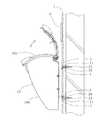
図3には、ポスト10を取付けたパネル本体1の側面図を示しており、この図に示すように、ポスト10の背面には、内面側からビス20がパネル本体1のポスト取付部4に対して挿通され、これによってポスト10はパネル本体1に対してビス止め固定される。また、パネル本体1は、躯体取付部3から挿入されたビス21によって壁面に対しビス止め固定されるが、この際、パネル本体1の背面と壁面との間に隙間が生じるように、パネル本体1と壁面との間にはスペーサ11が設けられ、躯体取付部3に挿入されたビス21は、スペーサ11を介して壁面に対して埋設される。このようにスペーサ11を設けたことにより、ポスト10を取付けるビス20の先端部が壁面と干渉しないようにすることができると共に、パネル本体1が壁面から浮き上がったように見せることができて、意匠性も向上させることができる。 FIG. 3 shows a side view of the
このように、鋳物で形成されるパネル本体1に対してポスト10を取付けることとしたので、壁面に対して機能パネルを簡易に取付けることができると共に、草花をモチーフとした複雑な形状を容易に形成することができ、意匠性を向上させることができる。また、躯体取付部3とポスト取付部4を近接配置したので、ポスト10を取付けることにより躯体取付部3を覆い隠すことができて、意匠性を向上させることができる。 As described above, since the
ここで、装飾部2のデザイン及びポスト10の構成については、本実施形態のものには限られない。次に説明する第2の実施形態は、これらが異なる機能パネルについて示している。図4には、第2の実施形態における機能パネルの平面図を、図5には、ポスト10を取付けた機能パネルの側面図を、それぞれ示している。 Here, the design of the
図4に示すように、本実施形態における機能パネルの構成は、第1の実施形態と略同様である。すなわち、機能パネルは鋳物から形成されるパネル本体1によって構成され、パネル本体1は、壁面に対する取付部である躯体取付部3と、ポスト10を取付けるポスト取付部4とが、互いに近接して設けられ、これらから外側に向かって延びるように、草花をモチーフとした装飾が施された装飾部2が設けられる。この装飾部2のデザインが、第1の実施形態の装飾部2とは異なっている。 As shown in FIG. 4, the configuration of the function panel in the present embodiment is substantially the same as that in the first embodiment. That is, the functional panel is constituted by a panel
また、図5に示すように、本実施形態の機能パネルに取付けられるポスト10は、開閉自在な上面部10aが円弧状に形成され、前面部10bは第1の実施形態と異なり開閉できないように構成されている。本実施形態におけるポスト10では、上面部10aが大きく開口するように形成されているため、郵便物等の出し入れはいずれも上面部10aを開放することによって行われる。 Further, as shown in FIG. 5, the
このように、本発明の機能パネルは、装飾部2のデザインを自由に設定でき、かつポスト10の構成についても、様々に対応させることができ、またブロック塀や建物の外壁などの壁面に対しても、開口を設けることなく簡易に取付けることができる。 As described above, the functional panel of the present invention can freely set the design of the
以上、本発明の実施形態について説明したが、本発明の適用は本実施形態に限られるものではなく、その技術的思想の範囲内において様々に適用されうるものである。 Although the embodiment of the present invention has been described above, the application of the present invention is not limited to this embodiment, and can be variously applied within the scope of the technical idea.
1 パネル本体
2 装飾部
3 躯体取付部
4 ポスト取付部
5 枠部
6 取付部
10 ポスト
11 スペーサDESCRIPTION OF
Claims (3)
Translated fromJapanese前記パネル本体は鋳物で形成され、草花をモチーフとした形状の装飾部と、壁面に対する固定をなす躯体取付部と、前面側にポストを取付けるポスト取付部とからなり、
前記躯体取付部とポスト取付部はそれぞれ略平坦面に形成されると共に、互いに近接して配置され、前記装飾部は前記躯体取付部またはポスト取付部から外側に向かって延びるように形成されると共に、表札またはインターホンの取付部が形成され、
前記取付部は表札またはインターホンが取付けられた際に、該表札またはインターホンが前記ポスト取付部に取付けられるポストと干渉しない位置に形成されることを特徴とする機能パネル。In the functional panel consisting of the panel body attached to the wall,
The panel body is formed of a casting, and includes a decorative portion having a flower motif as a motif, a housing mounting portion that is fixed to the wall surface, and a post mounting portion that attaches a post to the front side.
The housing mounting portion and the post mounting portion are each formed on a substantially flat surface and are arranged close to each other, and the decorative portion is formed to extend outward from the housing mounting portion or the post mounting portion. , Nameplate or intercom mounting part is formed,
The functional panel, wherein the mounting portion is formed at a position where the nameplate or intercom does not interfere with a post attached to the post mounting portion when the nameplate or intercom is attached.
Priority Applications (1)
| Application Number | Priority Date | Filing Date | Title |
|---|---|---|---|
| JP2007014462AJP2008179994A (en) | 2007-01-25 | 2007-01-25 | Functional panel |
Applications Claiming Priority (1)
| Application Number | Priority Date | Filing Date | Title |
|---|---|---|---|
| JP2007014462AJP2008179994A (en) | 2007-01-25 | 2007-01-25 | Functional panel |
Publications (1)
| Publication Number | Publication Date |
|---|---|
| JP2008179994Atrue JP2008179994A (en) | 2008-08-07 |
Family
ID=39724092
Family Applications (1)
| Application Number | Title | Priority Date | Filing Date |
|---|---|---|---|
| JP2007014462APendingJP2008179994A (en) | 2007-01-25 | 2007-01-25 | Functional panel |
Country Status (1)
| Country | Link |
|---|---|
| JP (1) | JP2008179994A (en) |
Cited By (9)
| Publication number | Priority date | Publication date | Assignee | Title |
|---|---|---|---|---|
| US8811065B2 (en) | 2005-09-02 | 2014-08-19 | Google Inc. | Performing error detection on DRAMs |
| US8819356B2 (en) | 2008-07-25 | 2014-08-26 | Google Inc. | Configurable multirank memory system with interface circuit |
| US8868829B2 (en) | 2006-07-31 | 2014-10-21 | Google Inc. | Memory circuit system and method |
| US8972673B2 (en) | 2006-07-31 | 2015-03-03 | Google Inc. | Power management of memory circuits by virtual memory simulation |
| US8977806B1 (en) | 2006-10-05 | 2015-03-10 | Google Inc. | Hybrid memory module |
| US9047976B2 (en) | 2006-07-31 | 2015-06-02 | Google Inc. | Combined signal delay and power saving for use with a plurality of memory circuits |
| US9171585B2 (en) | 2005-06-24 | 2015-10-27 | Google Inc. | Configurable memory circuit system and method |
| US9507739B2 (en) | 2005-06-24 | 2016-11-29 | Google Inc. | Configurable memory circuit system and method |
| US10013371B2 (en) | 2005-06-24 | 2018-07-03 | Google Llc | Configurable memory circuit system and method |
- 2007
- 2007-01-25JPJP2007014462Apatent/JP2008179994A/enactivePending
Cited By (9)
| Publication number | Priority date | Publication date | Assignee | Title |
|---|---|---|---|---|
| US9171585B2 (en) | 2005-06-24 | 2015-10-27 | Google Inc. | Configurable memory circuit system and method |
| US9507739B2 (en) | 2005-06-24 | 2016-11-29 | Google Inc. | Configurable memory circuit system and method |
| US10013371B2 (en) | 2005-06-24 | 2018-07-03 | Google Llc | Configurable memory circuit system and method |
| US8811065B2 (en) | 2005-09-02 | 2014-08-19 | Google Inc. | Performing error detection on DRAMs |
| US8868829B2 (en) | 2006-07-31 | 2014-10-21 | Google Inc. | Memory circuit system and method |
| US8972673B2 (en) | 2006-07-31 | 2015-03-03 | Google Inc. | Power management of memory circuits by virtual memory simulation |
| US9047976B2 (en) | 2006-07-31 | 2015-06-02 | Google Inc. | Combined signal delay and power saving for use with a plurality of memory circuits |
| US8977806B1 (en) | 2006-10-05 | 2015-03-10 | Google Inc. | Hybrid memory module |
| US8819356B2 (en) | 2008-07-25 | 2014-08-26 | Google Inc. | Configurable multirank memory system with interface circuit |
Similar Documents
| Publication | Publication Date | Title |
|---|---|---|
| JP2008179994A (en) | Functional panel | |
| USD615992S1 (en) | Icon for a portion of a display screen | |
| USD615553S1 (en) | Icon for a portion of a display screen | |
| USD615991S1 (en) | Icon for a portion of display screen | |
| JP6839815B2 (en) | Gate pillar | |
| USD568734S1 (en) | Canopy bed window box | |
| KR200391576Y1 (en) | post box | |
| CN219081308U (en) | Magnetic touch door structure | |
| JPH09144390A (en) | Sign post installation structure | |
| CN210902531U (en) | Two-sealing curtain box | |
| KR101100917B1 (en) | Cover assembly for mailbox with decorative panel | |
| KR200359562Y1 (en) | Distribution switch box | |
| KR20220017073A (en) | Mtal panel for interior and exterior decoration of building and construction method using the same | |
| CN207092828U (en) | The doorframe of Concealed door | |
| USD568735S1 (en) | Canopy bed window box | |
| CN207863773U (en) | Antitheft door | |
| JP3112213U (en) | Headstone protection cover | |
| CN201129124Y (en) | Novel cabin fireproof doorframe | |
| JPH10153018A (en) | Face body fitting column | |
| US20110061203A1 (en) | Eye a door | |
| WO2001006080A1 (en) | Openable screen element such as a door | |
| CN206015971U (en) | The curtain wall construction of additional decorative board | |
| KR200310197Y1 (en) | Wall mounting type mailbox | |
| CN202788419U (en) | Safe cabinet with glass door design | |
| KR200456522Y1 (en) | Posting board of furniture |