JP2008171685A - lighting equipment - Google Patents
lighting equipmentDownload PDFInfo
- Publication number
- JP2008171685A JP2008171685AJP2007003821AJP2007003821AJP2008171685AJP 2008171685 AJP2008171685 AJP 2008171685AJP 2007003821 AJP2007003821 AJP 2007003821AJP 2007003821 AJP2007003821 AJP 2007003821AJP 2008171685 AJP2008171685 AJP 2008171685A
- Authority
- JP
- Japan
- Prior art keywords
- reflector
- light source
- rod
- shaped light
- reflecting
- Prior art date
- Legal status (The legal status is an assumption and is not a legal conclusion. Google has not performed a legal analysis and makes no representation as to the accuracy of the status listed.)
- Pending
Links
- 238000005286illuminationMethods0.000claimsabstractdescription23
- 230000002093peripheral effectEffects0.000claimsdescription9
- 239000000463materialSubstances0.000description4
- 229910052782aluminiumInorganic materials0.000description3
- XAGFODPZIPBFFR-UHFFFAOYSA-NaluminiumChemical compound[Al]XAGFODPZIPBFFR-UHFFFAOYSA-N0.000description3
- 230000007423decreaseEffects0.000description3
- 241000219122CucurbitaSpecies0.000description1
- 235000009852Cucurbita pepoNutrition0.000description1
- RTAQQCXQSZGOHL-UHFFFAOYSA-NTitaniumChemical compound[Ti]RTAQQCXQSZGOHL-UHFFFAOYSA-N0.000description1
- 238000004378air conditioningMethods0.000description1
- 239000011248coating agentSubstances0.000description1
- 238000000576coating methodMethods0.000description1
- 229910052751metalInorganic materials0.000description1
- 239000002184metalSubstances0.000description1
- 229910052710siliconInorganic materials0.000description1
- 239000010703siliconSubstances0.000description1
- 239000010936titaniumSubstances0.000description1
- 229910052719titaniumInorganic materials0.000description1
Images


Classifications
- F—MECHANICAL ENGINEERING; LIGHTING; HEATING; WEAPONS; BLASTING
- F21—LIGHTING
- F21V—FUNCTIONAL FEATURES OR DETAILS OF LIGHTING DEVICES OR SYSTEMS THEREOF; STRUCTURAL COMBINATIONS OF LIGHTING DEVICES WITH OTHER ARTICLES, NOT OTHERWISE PROVIDED FOR
- F21V7/00—Reflectors for light sources
- F21V7/0025—Combination of two or more reflectors for a single light source
- F—MECHANICAL ENGINEERING; LIGHTING; HEATING; WEAPONS; BLASTING
- F21—LIGHTING
- F21V—FUNCTIONAL FEATURES OR DETAILS OF LIGHTING DEVICES OR SYSTEMS THEREOF; STRUCTURAL COMBINATIONS OF LIGHTING DEVICES WITH OTHER ARTICLES, NOT OTHERWISE PROVIDED FOR
- F21V7/00—Reflectors for light sources
- F21V7/04—Optical design
- F21V7/09—Optical design with a combination of different curvatures
- F—MECHANICAL ENGINEERING; LIGHTING; HEATING; WEAPONS; BLASTING
- F21—LIGHTING
- F21S—NON-PORTABLE LIGHTING DEVICES; SYSTEMS THEREOF; VEHICLE LIGHTING DEVICES SPECIALLY ADAPTED FOR VEHICLE EXTERIORS
- F21S8/00—Lighting devices intended for fixed installation
- F21S8/02—Lighting devices intended for fixed installation of recess-mounted type, e.g. downlighters
- F—MECHANICAL ENGINEERING; LIGHTING; HEATING; WEAPONS; BLASTING
- F21—LIGHTING
- F21Y—INDEXING SCHEME ASSOCIATED WITH SUBCLASSES F21K, F21L, F21S and F21V, RELATING TO THE FORM OR THE KIND OF THE LIGHT SOURCES OR OF THE COLOUR OF THE LIGHT EMITTED
- F21Y2103/00—Elongate light sources, e.g. fluorescent tubes
- F21Y2103/30—Elongate light sources, e.g. fluorescent tubes curved
- F21Y2103/37—U-shaped
- F—MECHANICAL ENGINEERING; LIGHTING; HEATING; WEAPONS; BLASTING
- F21—LIGHTING
- F21Y—INDEXING SCHEME ASSOCIATED WITH SUBCLASSES F21K, F21L, F21S and F21V, RELATING TO THE FORM OR THE KIND OF THE LIGHT SOURCES OR OF THE COLOUR OF THE LIGHT EMITTED
- F21Y2113/00—Combination of light sources
Landscapes
- Engineering & Computer Science (AREA)
- General Engineering & Computer Science (AREA)
- Non-Portable Lighting Devices Or Systems Thereof (AREA)
- Securing Globes, Refractors, Reflectors Or The Like (AREA)
- Optical Elements Other Than Lenses (AREA)
Abstract
Translated fromJapaneseDescription
Translated fromJapanese本発明は、建屋の天井等に設置されて下方の床面を照明するダウンライトに好適な照明器具に関する。 The present invention relates to a lighting fixture suitable for a downlight that is installed on a ceiling or the like of a building and illuminates a lower floor surface.
光源ランプと光源ランプの光を反射させる反射板とを有する照明器具において、反射板は、照明効率を左右する重要な構成部材である。 In a luminaire having a light source lamp and a reflector that reflects light from the light source lamp, the reflector is an important component that affects the illumination efficiency.
本願発明者は、先に特許文献1において、全体形状を笠状の多面体として、かつ、その内面の反射面をそれぞれ傾斜角度の異なる上下2段の傾斜部から形成した反射板を提案した。また、特許文献2において、傾斜部を上下3段以上にすることを提案した。この複数段構造の反射板によって、上下の傾斜部の傾斜角度を調整して光を反射させることにより、広範囲を均一に照明することが可能となった。 The inventor of the present application previously proposed in Japanese Patent Application Laid-Open No. H11-228707 a reflector having an overall shape as a shaded polyhedron, and a reflecting surface on the inner surface formed from two upper and lower inclined portions having different inclination angles. Moreover, in
しかし、照度を向上させるために複数の棒状光源ランプ(蛍光管ランプ)を使用する場合、棒状光源ランプどうしの間で光が干渉して打ち消し合うため、棒状光源ランプからの光が照明として有効利用されず、照度が不足するとともに、照明領域の平面形状がひょうたん状になるという問題があった。 However, when multiple rod-shaped light source lamps (fluorescent tube lamps) are used to improve the illuminance, the light from the rod-shaped light source lamps cancels each other due to interference between the rod-shaped light source lamps. However, there is a problem that the illumination area is insufficient and the planar shape of the illumination area becomes a gourd.
これに対して、本願発明者は特許文献3において、複数の棒状光源ランプを使用する場合には、反射板の天板部の中央付近に、外面を反射面とした反射体を反射板の開口側に向けて突出するように配置することが有効であることを開示した。 On the other hand, in the case of using a plurality of rod-shaped light source lamps in
しかし、特許文献3に開示されたものでは、棒状光源ランプと反射体との位置関係が最適化されておらず、照明効率には改善の余地があった。
本発明が解決しようとする課題は、複数の棒状光源ランプを有し、これを内部に反射体を有する反射板内に挿入して使用する照明器具において、棒状光源ランプと反射体との位置関係を最適化し、その照明効率を向上させることにある。 The problem to be solved by the present invention is a lighting fixture having a plurality of rod-shaped light source lamps inserted into a reflector having a reflector therein, and the positional relationship between the rod-shaped light source lamp and the reflector. Is to improve the lighting efficiency.
本願発明者が、鋭意検討を重ねた結果、上記のような照明器具の照明効率には、棒状光源ランプと反射体の突出長さが大きく影響を及ぼすことがわかった。そして、反射体の突出長さを、棒状光源ランプの突出長さの1/3〜3/4とすることによって、照明効率がさらに向上することがわかり、本発明を完成させるに至った。 As a result of extensive studies by the inventor of the present application, it has been found that the protruding lengths of the rod-shaped light source lamp and the reflector greatly affect the illumination efficiency of the lighting fixture as described above. And it turned out that illumination efficiency improves further by making the protrusion length of a reflector into 1/3-3/4 of the protrusion length of a rod-shaped light source lamp, and came to complete this invention.
すなわち、本発明の照明器具は、光を反射させるために内面を反射面とした笠状の反射板と、反射板の天板部近傍に基端部を固定して反射板内に挿入される複数の棒状光源ランプとを有する照明器具であって、前記反射板の天板部の中央付近に、外面を反射面とした反射体を反射板の開口側に向けて突出するように配置し、前記反射体の突出長さが、前記反射板内の棒状光源ランプの突出長さの1/3〜3/4であることを特徴とするものである。 That is, the lighting fixture of the present invention is inserted into the reflector plate with a base end portion fixed in the vicinity of the top plate portion of the reflector plate and a shade-shaped reflector plate whose inner surface is a reflection surface in order to reflect light. A lighting fixture having a plurality of rod-shaped light source lamps, arranged near the center of the top plate portion of the reflecting plate, so that a reflector having an outer surface as a reflecting surface protrudes toward the opening side of the reflecting plate, The protrusion length of the reflector is 1/3 to 3/4 of the protrusion length of the rod-shaped light source lamp in the reflector.
このように、反射体の突出長さを棒状光源ランプの突出長さの1/3〜3/4とすることによって、照明効率が向上する。逆に、反射体の突出長さが棒状光源ランプの突出長さの1/3未満では棒状光源ランプからの光が反射体で十分に反射されず、照明効率が低下する。また、反射体の突出長さが棒状光源ランプの突出長さの3/4を超えると、反射体の存在がかえって反射板内での光の反射の邪魔になり、照明すべき床面等に影ができることがある。 Thus, illumination efficiency improves by making the protrusion length of a reflector into 1/3-3/4 of the protrusion length of a rod-shaped light source lamp. On the contrary, if the protruding length of the reflector is less than 1/3 of the protruding length of the rod-shaped light source lamp, the light from the rod-shaped light source lamp is not sufficiently reflected by the reflector, and the illumination efficiency is lowered. Also, if the projecting length of the reflector exceeds 3/4 of the projecting length of the rod-shaped light source lamp, the presence of the reflector will obstruct the reflection of light in the reflecting plate, which may cause the floor surface to be illuminated, etc. There may be shadows.
本発明において、反射体の反射面と棒状光源ランプの外周面との距離は8mm以上とすることが好ましい。より好ましくは、8〜10mmとする。前記距離が8mm未満になると、反射体の反射面による反射効率が低下する。 In the present invention, the distance between the reflecting surface of the reflector and the outer peripheral surface of the rod-shaped light source lamp is preferably 8 mm or more. More preferably, it is 8-10 mm. When the distance is less than 8 mm, the reflection efficiency due to the reflection surface of the reflector decreases.
また、棒状光源ランプが角柱状の形状を有する場合、その棒状光源ランプの外周面と、これに対向する反射体の反射面とが非平行となるように配置することが好ましい。これによって、棒状光源ランプからの光が当該棒状光源ランプの位置とは異なる方向に反射されるので、その反射光を照明として効率的に利用することができ、照明効率が向上する。 When the rod-shaped light source lamp has a prismatic shape, it is preferable that the rod-shaped light source lamp is disposed so that the outer peripheral surface of the rod-shaped light source lamp is not parallel to the reflecting surface of the reflector facing the rod-shaped light source lamp. Thereby, the light from the rod-shaped light source lamp is reflected in a direction different from the position of the rod-shaped light source lamp, so that the reflected light can be efficiently used as illumination, and the illumination efficiency is improved.
さらに、反射体の反射面の数は3面以上とすることが好ましい。反射体の反射面の数を3面以上とすることで、棒状光源ランプからの光を多方向に反射することができ、照明の均一性が向上する。 Furthermore, the number of reflecting surfaces of the reflector is preferably three or more. By setting the number of reflecting surfaces of the reflector to three or more, light from the rod-shaped light source lamp can be reflected in multiple directions, and the uniformity of illumination is improved.
本発明によれば、複数の棒状光源ランプからの光が、反射板の天板部の中央付近に配置した反射体により効率的に反射されるので、照明器具の照明効率を向上させることができる。したがって、従来よりも少ない棒状光源ランプの数で、従来と同じ照度を得ることができるようになり、大幅に電力使用量を削減できる。また、発熱量が減少して建屋内の空調効率を向上させることができる。 According to the present invention, the light from the plurality of rod-shaped light source lamps is efficiently reflected by the reflector disposed in the vicinity of the center of the top plate portion of the reflector, so that the illumination efficiency of the lighting fixture can be improved. . Therefore, it becomes possible to obtain the same illuminance as in the past with a smaller number of rod-shaped light source lamps than in the past, and the amount of power used can be greatly reduced. Moreover, the calorific value can be reduced and the air conditioning efficiency in the building can be improved.
以下、本発明をダウンライトに適用した添付図に示す実施例に基づいて具体的に説明する。 Hereinafter, the present invention will be described in detail based on an embodiment shown in the accompanying drawings in which the present invention is applied to a downlight.
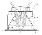
図1は、本発明に係るダウンライトの第1実施例を示す断面図、図2は、図1のダウンライトに使用した反射板を示す斜視図である。 FIG. 1 is a sectional view showing a first embodiment of a downlight according to the present invention, and FIG. 2 is a perspective view showing a reflector used in the downlight of FIG.
図1に示すダウンライト10は、蛍光管ランプからなる2本の棒状光源ランプ1と、棒状光源ランプ1の光を反射させるための反射板2及び反射体3と、反射板2を固定する本体部4を備える。 A
2本の棒状光源ランプ1は、その上端部(基端部)が反射板2の天板部2a近傍に固定され、発光部分は反射板2内に位置している。また、2本の棒状光源ランプ1は、図1に示すように、互いに平行に配置されている。 The two rod-shaped
反射板2は、底面形状(横断面形状)が正18角形の笠状の18面体からなり、その内面の反射面は、それぞれ傾斜角度の異なる第1傾斜部2b、第2傾斜部2c、第3傾斜部2d及び第4傾斜部2eからなる上下4段の傾斜部から形成されている。反射板2の大きさや各傾斜部2b〜2eの傾斜角度及び長さは、ダウンライト10を設置する場所の天井高さや照明範囲などの条件に応じて適宜設定される。 The reflecting
反射板2の素材はアルミニウムであり、その内面の反射面はアルミニウムの表面にチタン・シリコンをコーティングすることによって鏡面状としている。反射板の素材としてはアルミニウムに限られず、例えば金属板を使用して内面を鏡面加工してもよい。なお、図2中の符号2fは、2本の棒状光源ランプを挿通するための切欠きである。 The material of the reflecting
反射体3は、2本の棒状光源ランプ1に挟まれた反射板2の天板部2aの中央付近内面から下方(反射板の開口側)に向けて突出するように設けられている。この反射体3は4角柱状をなし、その4つの外側面が反射面3aとなっている。 The
本体部4は、その下端部外周に外方に突出したリング状の支持部材4aを有しており、この支持部材4aを天井Tの裏面に載置することにより、天井Tの裏面にダウンライト10全体が懸架される。 The
以上の構成において、本発明では、反射体3の突出長さd1が反射板2内の棒状光源ランプ1の突出長さd2の1/3〜3/4となるように設定する。そして好ましくは、反射体3の反射面3aと棒状光源ランプ1の外周面との距離(最短距離)d3が8mm以上となるように設定する。 In the above configuration, in the present invention, the protrusion length d1 of the
ここで、図3には、棒状光源ランプ1と反射体3の好ましい配置関係を示す。同図に示すように、棒状光源ランプ1が角柱状の形状を有する場合、その棒状光源ランプ1の外周面と、これに対向する反射体3の反射面3aとが非平行となるように配置することが好ましい。これによって、棒状光源ランプ1からの光が当該棒状光源ランプ1の位置とは異なる方向に反射されるので、その反射光を照明として効率的に利用することができ、照明効率が向上する。ここで、棒状光源ランプ1が角柱状の形状を有するとは、完全な角柱ではなくとも棒状光源ランプ1の外形(輪郭)がほぼ角柱である場合も含む概念である。 Here, in FIG. 3, the preferable arrangement | positioning relationship of the rod-shaped
以上のダウンライト10によれば、2本の棒状光源ランプ1から反射板2の中心方向に発する光は、干渉することなく、反射体3の反射面3aによって反射され、さらに、その反射光が反射板2内面の反射面で複数回反射されて床面を照明する。また、2本の棒状光源ランプ1から反射板2の外周方向に発する光も反射板2内面の反射面で複数回反射して床面を照明する。このように、棒状光源ランプ1から発する光の全てを照明用として有効に利用でき、照明効率が向上する。 According to the
図4は、本発明に係るダウンライトの第2実施例を示す断面図、図5は、図4のダウンライトに使用した反射板を示す斜視図である。 FIG. 4 is a sectional view showing a second embodiment of the downlight according to the present invention, and FIG. 5 is a perspective view showing a reflector used in the downlight of FIG.
図4に示すダウンライト10では、3本の棒状光源ランプ1を反射体2の切欠き2fから反射体2内に挿入する。 In the
3本の棒状光源ランプ1は、その上端部(基端部)が反射板2の天板部2a近傍に固定され、発光部分は反射板2内に位置している。また、3本の棒状光源ランプ1は、図4に示すように、下方に向かうにしたがって相互の間隔が狭くなるように配置されている。 The three rod-shaped
反射板2は、底面形状(横断面形状)が正18角形の笠状の18面体からなり、その内面の反射面は、それぞれ傾斜角度の異なる第1傾斜部2b、第2傾斜部2c及び第3傾斜部2dからなる上下3段の傾斜部から形成されている。反射板2の大きさや各傾斜部2b〜2dの傾斜角度及び長さは、ダウンライト10を設置する場所の天井高さや照明範囲などの条件に応じて適宜設定される。なお、反射板2の素材等については実施例1で説明したとおりである。 The
反射体3は、3本の棒状光源ランプ1に挟まれた反射板2の天板部2aの中央付近内面から下方(反射板の開口側)に向けて突出するように設けられている。この反射体3は6角錐状をなし、その6つの外側面が反射面3aとなっている。 The
本体部4は、実施例1と同様の構成を有しており、その下端部外周で外方に突出したリング状の支持部材4aを天井Tの裏面に載置することにより、天井Tの裏面にダウンライト10全体が懸架される。 The
この実施例においても、反射体3の突出長さが反射板2内の棒状光源ランプ1の突出長さの1/3〜3/4となるように設定する。なお、この実施例のように、棒状光源ランプ1が傾斜して挿入されている場合、その突出長さは垂直方向に沿った突出長さとする。同様に、反射体3の突出長さも垂直方向に沿った突出長さとする。 Also in this embodiment, the protruding length of the
さらに好ましくは、この実施例においても反射体3の反射面3aと棒状光源ランプ1の外周面との距離(最短距離)が8mm以上となるように設定する。 More preferably, also in this embodiment, the distance (shortest distance) between the reflecting
この実施例によっても、先の実施例1と同様に、照明効率を向上させることができる。 Also in this embodiment, the illumination efficiency can be improved as in the first embodiment.
図6は、本発明に係るダウンライトの第3実施例を示す断面図、図7は、図6のダウンライトに使用した反射板を示す斜視図である。 6 is a cross-sectional view showing a third embodiment of the downlight according to the present invention, and FIG. 7 is a perspective view showing a reflector used in the downlight of FIG.
図6に示すダウンライト10では、2本の棒状光源ランプ1を反射体2の切欠き2fから反射体2内に挿入する。 In the
2本の棒状光源ランプ1は、その上端部が反射板2の天板部2a近傍に固定され、発光部分は反射板2内に位置している。また、2本の棒状光源ランプ1は、図6に示すように、下方に向かうにしたがって相互の間隔が狭くなるようV字状に配置されている。 The two bar-shaped
反射板2は、底面形状(横断面形状)が正18角形の笠状の18面体からなり、その内面の反射面は、それぞれ傾斜角度の異なる第1傾斜部2b、第2傾斜部2c及び第3傾斜部2dからなる上下3段の傾斜部から形成されている。反射板2の大きさや各傾斜部2b〜2dの傾斜角度及び長さは、ダウンライト10を設置する場所の天井高さや照明範囲などの条件に応じて適宜設定される。なお、反射板2の素材等については実施例1で説明したとおりである。 The reflecting
反射体3は、2本の棒状光源ランプ1に挟まれた反射板2の天板部2aの中央付近内面から下方(反射板の開口側)に向けて突出するように設けられており、2本の棒状光源ランプ1と対向する両側面が反射面3aとされている。この両側面の反射面3a,3aは、下方に向かうにしたがって相互の間隔が狭くなるようV字状に形成されている。 The
本体部4は、実施例1と同様の構成を有しており、その下端部外周で外方に突出したリング状の支持部材4aを天井Tの裏面に載置することにより、天井Tの裏面にダウンライト10全体が懸架される。 The
この実施例においても、反射体3の突出長さが反射板2内の棒状光源ランプ1の突出長さの1/3〜3/4となるように設定する。また、好ましくは、この実施例においても反射体3の反射面3aと棒状光源ランプ1の外周面との距離(最短距離)d3が8mm以上となるように設定する。 Also in this embodiment, the protruding length of the
この実施例によっても、先の実施例1及び2と同様に、照明効率を向上させることができる。 Also in this embodiment, the illumination efficiency can be improved as in the first and second embodiments.
本発明は、天井に取り付けられるダウンライトとしてだけでなく、壁面、床面に取り付ける照明器具としても利用可能である。 The present invention can be used not only as a downlight attached to a ceiling, but also as a lighting fixture attached to a wall surface and a floor surface.
1 棒状光源ランプ
2 反射板
2a 天板部
2b 第1傾斜部
2c 第2傾斜部
2d 第3傾斜部
2e 第4傾斜部
2f 切欠き
3 反射体
3a 反射面
4 本体部
4a 支持部材DESCRIPTION OF
Claims (4)
Translated fromJapanese前記反射板の天板部の中央付近に、外面を反射面とした反射体を反射板の開口側に向けて突出するように配置し、
前記反射体の突出長さが、前記反射板内の棒状光源ランプの突出長さの1/3〜3/4である照明器具。Illumination having a shade-shaped reflecting plate whose inner surface is a reflecting surface for reflecting light, and a plurality of rod-shaped light source lamps that are inserted into the reflecting plate with a proximal end fixed in the vicinity of the top plate portion of the reflecting plate An instrument,
In the vicinity of the center of the top plate portion of the reflecting plate, a reflector having an outer surface as a reflecting surface is arranged so as to protrude toward the opening side of the reflecting plate,
The lighting fixture whose protrusion length of the said reflector is 1/3-3/4 of the protrusion length of the rod-shaped light source lamp in the said reflecting plate.
Priority Applications (5)
| Application Number | Priority Date | Filing Date | Title |
|---|---|---|---|
| JP2007003821AJP2008171685A (en) | 2007-01-11 | 2007-01-11 | lighting equipment |
| KR1020097014885AKR20090113828A (en) | 2007-01-11 | 2007-04-10 | Lighting fixtures |
| CNA2007800497154ACN101606018A (en) | 2007-01-11 | 2007-04-10 | Lighting apparatus |
| US12/522,475US20100135016A1 (en) | 2007-01-11 | 2007-04-10 | Lamp unit |
| PCT/JP2007/057916WO2008084562A1 (en) | 2007-01-11 | 2007-04-10 | Illuminator |
Applications Claiming Priority (1)
| Application Number | Priority Date | Filing Date | Title |
|---|---|---|---|
| JP2007003821AJP2008171685A (en) | 2007-01-11 | 2007-01-11 | lighting equipment |
Publications (1)
| Publication Number | Publication Date |
|---|---|
| JP2008171685Atrue JP2008171685A (en) | 2008-07-24 |
Family
ID=39608463
Family Applications (1)
| Application Number | Title | Priority Date | Filing Date |
|---|---|---|---|
| JP2007003821APendingJP2008171685A (en) | 2007-01-11 | 2007-01-11 | lighting equipment |
Country Status (5)
| Country | Link |
|---|---|
| US (1) | US20100135016A1 (en) |
| JP (1) | JP2008171685A (en) |
| KR (1) | KR20090113828A (en) |
| CN (1) | CN101606018A (en) |
| WO (1) | WO2008084562A1 (en) |
Families Citing this family (13)
| Publication number | Priority date | Publication date | Assignee | Title |
|---|---|---|---|---|
| WO2011004297A1 (en)* | 2009-07-08 | 2011-01-13 | Koninklijke Philips Electronics N.V. | An illumination device |
| US8901845B2 (en) | 2009-09-24 | 2014-12-02 | Cree, Inc. | Temperature responsive control for lighting apparatus including light emitting devices providing different chromaticities and related methods |
| US10264637B2 (en) | 2009-09-24 | 2019-04-16 | Cree, Inc. | Solid state lighting apparatus with compensation bypass circuits and methods of operation thereof |
| US9713211B2 (en) | 2009-09-24 | 2017-07-18 | Cree, Inc. | Solid state lighting apparatus with controllable bypass circuits and methods of operation thereof |
| US8777449B2 (en) | 2009-09-25 | 2014-07-15 | Cree, Inc. | Lighting devices comprising solid state light emitters |
| USD633099S1 (en)* | 2009-09-25 | 2011-02-22 | Cree, Inc. | Light engine for a lighting device |
| US9068719B2 (en)* | 2009-09-25 | 2015-06-30 | Cree, Inc. | Light engines for lighting devices |
| US8602579B2 (en) | 2009-09-25 | 2013-12-10 | Cree, Inc. | Lighting devices including thermally conductive housings and related structures |
| US9285103B2 (en)* | 2009-09-25 | 2016-03-15 | Cree, Inc. | Light engines for lighting devices |
| US8476836B2 (en) | 2010-05-07 | 2013-07-02 | Cree, Inc. | AC driven solid state lighting apparatus with LED string including switched segments |
| US9839083B2 (en) | 2011-06-03 | 2017-12-05 | Cree, Inc. | Solid state lighting apparatus and circuits including LED segments configured for targeted spectral power distribution and methods of operating the same |
| US8742671B2 (en) | 2011-07-28 | 2014-06-03 | Cree, Inc. | Solid state lighting apparatus and methods using integrated driver circuitry |
| USD718489S1 (en)* | 2014-04-01 | 2014-11-25 | Cooper Technologies Company | Recessed luminaire housing top |
Citations (2)
| Publication number | Priority date | Publication date | Assignee | Title |
|---|---|---|---|---|
| JPS61225708A (en)* | 1985-03-29 | 1986-10-07 | 東芝ライテック株式会社 | lighting equipment |
| JP2006059707A (en)* | 2004-08-20 | 2006-03-02 | Miyoji Ishibashi | Lighting fixture |
Family Cites Families (3)
| Publication number | Priority date | Publication date | Assignee | Title |
|---|---|---|---|---|
| US4520436A (en)* | 1983-03-25 | 1985-05-28 | Nrg Inc. Mn | Lamp apparatus |
| US6068388A (en)* | 1996-02-28 | 2000-05-30 | Eppi Lighting, Inc. | Dual reflector lighting system |
| US7252406B2 (en)* | 2003-04-04 | 2007-08-07 | Purespectrum Llc | Fluorescent lamp system using reflectors |
- 2007
- 2007-01-11JPJP2007003821Apatent/JP2008171685A/enactivePending
- 2007-04-10USUS12/522,475patent/US20100135016A1/ennot_activeAbandoned
- 2007-04-10KRKR1020097014885Apatent/KR20090113828A/ennot_activeWithdrawn
- 2007-04-10CNCNA2007800497154Apatent/CN101606018A/enactivePending
- 2007-04-10WOPCT/JP2007/057916patent/WO2008084562A1/enactiveApplication Filing
Patent Citations (2)
| Publication number | Priority date | Publication date | Assignee | Title |
|---|---|---|---|---|
| JPS61225708A (en)* | 1985-03-29 | 1986-10-07 | 東芝ライテック株式会社 | lighting equipment |
| JP2006059707A (en)* | 2004-08-20 | 2006-03-02 | Miyoji Ishibashi | Lighting fixture |
Also Published As
| Publication number | Publication date |
|---|---|
| WO2008084562A1 (en) | 2008-07-17 |
| KR20090113828A (en) | 2009-11-02 |
| CN101606018A (en) | 2009-12-16 |
| US20100135016A1 (en) | 2010-06-03 |
Similar Documents
| Publication | Publication Date | Title |
|---|---|---|
| JP2008171685A (en) | lighting equipment | |
| JP5927674B2 (en) | Illumination device and lens suitable for such illumination device | |
| JP2009026584A (en) | Luminaire | |
| US20110310603A1 (en) | Light fixtures | |
| JP2003092006A (en) | Lighting equipment and lighting | |
| US10774529B2 (en) | Ceiling tile with integrated lighting and ceiling system | |
| JP4436351B2 (en) | Luminaire lens and luminaire including the lens | |
| US20210116085A1 (en) | Luminaire | |
| CN206626458U (en) | Lamps and Lighting Systems | |
| EP1792119B1 (en) | Luminaire with louver members | |
| WO2012035841A1 (en) | Led illumination device | |
| JP4410636B2 (en) | lighting equipment | |
| JP5241018B2 (en) | lighting equipment | |
| WO2009107193A1 (en) | Illuminating method | |
| JP4919506B2 (en) | lighting equipment | |
| JP2010092611A (en) | Reflector, and lighting device using the same | |
| JP3106768U (en) | lighting equipment | |
| JP2005346968A (en) | Lighting fixture | |
| KR101145844B1 (en) | Illuminating system that use light diffusion panel and this | |
| JP2010176904A (en) | Light emitting device | |
| JP2009295424A (en) | Luminaire | |
| JP2012084457A (en) | Lighting system | |
| KR200269104Y1 (en) | Lampshade for decorative illuminator | |
| JP5740568B2 (en) | lighting equipment | |
| JP3114124U6 (en) | lighting equipment |
Legal Events
| Date | Code | Title | Description |
|---|---|---|---|
| A621 | Written request for application examination | Free format text:JAPANESE INTERMEDIATE CODE: A621 Effective date:20100112 | |
| A131 | Notification of reasons for refusal | Free format text:JAPANESE INTERMEDIATE CODE: A131 Effective date:20120113 | |
| A521 | Request for written amendment filed | Free format text:JAPANESE INTERMEDIATE CODE: A821 Effective date:20120215 | |
| A711 | Notification of change in applicant | Free format text:JAPANESE INTERMEDIATE CODE: A711 Effective date:20120215 | |
| A521 | Request for written amendment filed | Free format text:JAPANESE INTERMEDIATE CODE: A821 Effective date:20120215 | |
| A02 | Decision of refusal | Free format text:JAPANESE INTERMEDIATE CODE: A02 Effective date:20120608 |