JP2008167866A - Diagnostic robot, and control method and control program of diagnostic robot - Google Patents
Diagnostic robot, and control method and control program of diagnostic robotDownload PDFInfo
- Publication number
- JP2008167866A JP2008167866AJP2007002741AJP2007002741AJP2008167866AJP 2008167866 AJP2008167866 AJP 2008167866AJP 2007002741 AJP2007002741 AJP 2007002741AJP 2007002741 AJP2007002741 AJP 2007002741AJP 2008167866 AJP2008167866 AJP 2008167866A
- Authority
- JP
- Japan
- Prior art keywords
- palpation
- user
- reaction
- unit
- pressing
- Prior art date
- Legal status (The legal status is an assumption and is not a legal conclusion. Google has not performed a legal analysis and makes no representation as to the accuracy of the status listed.)
- Pending
Links
- 238000000034methodMethods0.000titleclaimsabstractdescription40
- 238000002559palpationMethods0.000claimsabstractdescription116
- 230000037237body shapeEffects0.000claimsdescription24
- 230000008859changeEffects0.000claimsdescription17
- 230000004044responseEffects0.000claimsdescription13
- 238000003745diagnosisMethods0.000claimsdescription5
- 230000003902lesionEffects0.000abstract3
- 230000000694effectsEffects0.000description15
- 230000008569processEffects0.000description12
- 238000010586diagramMethods0.000description11
- 238000010191image analysisMethods0.000description11
- 238000005259measurementMethods0.000description7
- 210000002310elbow jointAnatomy0.000description5
- 210000000323shoulder jointAnatomy0.000description5
- 210000003857wrist jointAnatomy0.000description5
- 239000013256coordination polymerSubstances0.000description4
- 238000012544monitoring processMethods0.000description4
- 230000003187abdominal effectEffects0.000description3
- 230000005236sound signalEffects0.000description2
- 125000002066L-histidyl groupChemical group[H]N1C([H])=NC(C([H])([H])[C@](C(=O)[*])([H])N([H])[H])=C1[H]0.000description1
- 230000008901benefitEffects0.000description1
- 239000008280bloodSubstances0.000description1
- 210000004369bloodAnatomy0.000description1
- 230000000747cardiac effectEffects0.000description1
- 230000010485copingEffects0.000description1
- 230000006870functionEffects0.000description1
- 238000003384imaging methodMethods0.000description1
- 230000007246mechanismEffects0.000description1
- 239000004065semiconductorSubstances0.000description1
Images


Landscapes
- Manipulator (AREA)
- Measurement Of The Respiration, Hearing Ability, Form, And Blood Characteristics Of Living Organisms (AREA)
Abstract
Description
Translated fromJapaneseこの発明は、例えば、会話を十分に行うことができない子供(例えば、1〜3歳児)の患部を探し当てる診断ロボット、診断ロボットの制御方法及び制御プログラムに関するものである。 The present invention relates to a diagnostic robot, a diagnostic robot control method, and a control program, for example, for finding an affected part of a child (for example, a 1 to 3 year old child) who cannot sufficiently talk.
従来の診断ロボットは、車両の診断部位を撮影する撮影部と、正常時における撮影画像を保持する画像保持部とを搭載し、撮影部により撮影された診断部位の撮影画像と正常時における撮影画像を比較して、その診断部位の故障を診断するものである(例えば、特許文献1を参照)。
即ち、従来の診断ロボットは、あくまでも、車両などの機械の故障を診断するものであって、人間を診断するものとは本質的に異なっている。A conventional diagnostic robot is equipped with an imaging unit that images a diagnostic part of a vehicle and an image holding part that holds a captured image in a normal state. Are compared, and the failure of the diagnosis part is diagnosed (see, for example, Patent Document 1).
That is, the conventional diagnostic robot is merely for diagnosing a failure of a machine such as a vehicle, and is essentially different from that for diagnosing a human being.
従来の診断ロボットは以上のように構成されているので、車両などの機械の故障を診断することができるが、例えば、会話を十分に行うことができない子供(例えば、1〜3歳児)の患部を探し当てることができないなどの課題があった。 Since the conventional diagnostic robot is configured as described above, it can diagnose a failure of a machine such as a vehicle, but, for example, an affected part of a child (for example, a 1 to 3 year old child) who cannot perform a conversation sufficiently There was a problem such as being unable to find.
この発明は上記のような課題を解決するためになされたもので、例えば、会話を十分に行うことができない子供の患部を探し当てることができる診断ロボット、診断ロボットの制御方法及び制御プログラムを得ることを目的とする。 The present invention has been made to solve the above-described problems. For example, a diagnostic robot, a diagnostic robot control method, and a control program capable of finding an affected area of a child who cannot sufficiently communicate can be obtained. With the goal.
請求項1記載の発明に係る診断ロボットは、押し当て手段により触診用部材が押し当てられている状態にあるときのユーザの反応を観測する反応観測手段を設け、患部認定手段が触診ポイント設定手段により設定された1以上の触診ポイントの中で、反応観測手段により観測されたユーザの反応が最も大きい触診ポイントを特定して、その触診ポイントを患部に認定するようにしたものである。 The diagnostic robot according to the first aspect of the present invention is provided with reaction observation means for observing a user's reaction when the palpation member is pressed by the pressing means, and the affected part recognition means is the palpation point setting means. Among the one or more palpation points set by the above, the palpation point having the largest user response observed by the reaction observation means is specified, and the palpation point is identified as an affected part.
請求項1記載の発明によれば、例えば、会話を十分に行うことができない子供の患部を探し当てることができる効果が得られる。 According to the first aspect of the present invention, for example, an effect of finding an affected part of a child who cannot sufficiently perform a conversation can be obtained.
請求項2記載の発明に係る診断ロボットは、押し当て手段により触診用部材が押し当てられている状態にあるときのユーザを撮影し、ユーザの映像の変化量をユーザの反応として観測するようにしたものである。 A diagnostic robot according to a second aspect of the present invention captures a user when the palpation member is pressed by the pressing means, and observes a change amount of the user's video as a user's reaction. It is a thing.
請求項2記載の発明によれば、ユーザが会話を十分に行うことができない場合でも、痛い部位を調べることができる効果が得られる。 According to the second aspect of the present invention, there is an effect that the painful part can be examined even when the user cannot sufficiently talk.
請求項3記載の発明に係る診断ロボットは、押し当て手段により触診用部材が押し当てられている状態にあるときのユーザの声を集音し、その声の音量をユーザの反応として観測するようにしたものである。 The diagnostic robot according to the third aspect of the invention collects the voice of the user when the palpation member is pressed by the pressing means, and observes the volume of the voice as a response of the user. It is a thing.
請求項3記載の発明によれば、ユーザが会話を十分に行うことができない場合でも、痛い部位を調べることができる効果が得られる。 According to the third aspect of the present invention, there is an effect that the painful part can be examined even when the user cannot sufficiently perform the conversation.
請求項4記載の発明に係る診断ロボットは、患部認定手段により認定された患部の位置を示す情報を閲覧可能な記録媒体に登録する患部情報登録手段を設けるようにしたものである。 According to a fourth aspect of the present invention, there is provided a diagnosis robot according to a fourth aspect of the present invention, wherein an affected part information registration unit is provided for registering information indicating a position of an affected part recognized by the affected part recognition unit in a browsing recording medium.
請求項4記載の発明によれば、例えば、家族や医師などが本格的な治療を行う前に、患部を把握することができる効果が得られる。 According to the fourth aspect of the present invention, for example, an effect can be obtained in which the affected part can be grasped before a family, a doctor or the like performs full-scale treatment.
請求項5記載の発明に係る診断ロボットは、押し当て手段が触診ポイント設定手段により設定された触診ポイントに触診用部材を押し当てる際、ユーザに問い掛けを行うようにしたものである。 According to the fifth aspect of the present invention, when the pressing means presses the palpation member against the palpation point set by the palpation point setting means, the user is inquired.
請求項5記載の発明によれば、触診が行われている旨をユーザが容易に理解することができる効果が得られる。 According to the fifth aspect of the present invention, there is an effect that the user can easily understand that palpation is performed.
請求項6記載の発明に係る診断ロボットは、ユーザのバイタルを測定し、そのバイタルを示す情報を閲覧可能な記録媒体に登録するバイタル情報登録手段を設けるようにしたものである。 According to a sixth aspect of the present invention, there is provided a diagnostic robot according to a sixth aspect of the present invention, wherein a vital information registration unit is provided for measuring a user's vitals and registering information indicating the vitals in a viewable recording medium.
請求項6記載の発明によれば、例えば、家族や医師などが患者の状態を容易に把握することができる効果が得られる。 According to the sixth aspect of the invention, for example, there is an effect that a family, a doctor, or the like can easily grasp the patient's condition.
請求項7記載の発明に係る診断ロボットの制御方法は、押し当て手段により触診用部材が押し当てられている状態にあるときのユーザの反応を観測する反応観測ステップを設け、患部認定手段が触診ポイント設定手段により設定された1以上の触診ポイントの中で、反応観測手段により観測されたユーザの反応が最も大きい触診ポイントを特定して、その触診ポイントを患部に認定するようにしたものである。 According to a seventh aspect of the present invention, there is provided a diagnostic robot control method comprising: a reaction observation step of observing a user's reaction when a palpation member is pressed by a pressing unit; Among the one or more palpation points set by the point setting means, a palpation point having the largest user response observed by the reaction observation means is specified, and the palpation point is recognized as an affected part. .
請求項7記載の発明によれば、例えば、会話を十分に行うことができない子供の患部を探し当てることができる効果が得られる。 According to the seventh aspect of the present invention, for example, an effect of finding an affected part of a child who cannot sufficiently perform a conversation can be obtained.
請求項8記載の発明に係る診断ロボットの制御プログラムは、押し当て処理手順により触診用部材が押し当てられている状態にあるときのユーザの反応を観測する反応観測処理手順を設け、患部認定処理手順が触診ポイント設定処理手順により設定された1以上の触診ポイントの中で、反応観測処理手順により観測されたユーザの反応が最も大きい触診ポイントを特定して、その触診ポイントを患部に認定するようにしたものである。 The diagnostic robot control program according to
請求項8記載の発明によれば、例えば、会話を十分に行うことができない子供の患部を探し当てることができる効果が得られる。 According to the eighth aspect of the present invention, for example, an effect of finding an affected part of a child who cannot sufficiently perform a conversation can be obtained.
この発明によれば、押し当て手段により触診用部材が押し当てられている状態にあるときのユーザの反応を観測する反応観測手段を設け、患部認定手段が触診ポイント設定手段により設定された1以上の触診ポイントの中で、反応観測手段により観測されたユーザの反応が最も大きい触診ポイントを特定して、その触診ポイントを患部に認定するように構成したので、例えば、会話を十分に行うことができない子供の患部を探し当てることができる効果がある。 According to this invention, the reaction observation means for observing the reaction of the user when the palpation member is being pressed by the pressing means is provided, and the affected part recognition means is one or more set by the palpation point setting means Since the palpation point with the greatest user response observed by the reaction observation means is identified and the palpation point is identified as the affected area, for example, sufficient conversation can be performed. It has the effect of finding the affected area of a child who cannot.
実施の形態1.
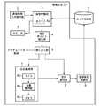
図1はこの発明の実施の形態1による診断ロボットの内部を示す構成図であり、図1において、カルテ記録部1は例えば家族や医師などが携帯端末やパソコンなどを使用して閲覧することが可能な電子的な記録媒体であり、患者の個人情報(例えば、氏名、年齢、住所、電話番号、血液型、体型(身長、体重、座高、胸囲、腹囲、腰囲など))が記録されているカルテを記憶している。なお、カルテ記録部1は電子的な記録媒体であれば、メディアの種別は如何なるものであってもよい。したがって、例えば、ハードディスクや、データベースなどで構成することができる。
患者情報入力受付部2は例えばキーボードやマウスなどのマンマシンインタフェースから構成されており、患者である子供の個人情報(例えば、氏名)の入力を受け付ける処理を実施する。Embodiment 1 FIG.
FIG. 1 is a block diagram showing the inside of a diagnostic robot according to Embodiment 1 of the present invention. In FIG. 1, a medical record recording unit 1 can be viewed by, for example, a family member or a doctor using a portable terminal or a personal computer. A possible electronic recording medium that records patient's personal information (eg name, age, address, phone number, blood type, body type (height, weight, sitting height, chest circumference, waist circumference, waist circumference, etc.)) I remember the medical record. As long as the medical record recording unit 1 is an electronic recording medium, any type of medium may be used. Therefore, for example, it can be configured by a hard disk or a database.
The patient information
体型把握部3は患者情報入力受付部2により入力が受け付けられた個人情報をキーにして、カルテ記録部1から患者である子供の体型情報を収集する処理を実施する。
ただし、体型把握部3は、例えば子供だけが自宅にいるような状況では、子供が患者情報入力受付部2を操作して、個人情報の入力を行うことができないので、例えば、内蔵しているカメラ3aを用いて、患者である子供を撮影し、子供の映像を解析して体型を把握する。
触診ポイント設定部4は体型把握部3により収集された子供の体型情報を参照して、N箇所の触診ポイントPn(n=1,2,・・・,N)を設定する処理を実施する。
なお、患者情報入力受付部2、体型把握部3及び触診ポイント設定部4から触診ポイント設定手段が構成されている。The body
However, the body
The palpation
The patient information
押し当て部5は例えばロボットの手を駆動するアクチュエータを制御して、触診ポイント設定部4により設定された触診ポイントP1〜PNにロボットの手を押し当てる処理を実施する。なお、押し当て部5は押し当て手段を構成している。
反応観測部6は例えばカメラ6aと画像解析部6bから構成されており、押し当て部5によりロボットの手が押し当てられている状態にあるときのユーザの反応を観測する処理を実施する。なお、反応観測部6は反応観測手段を構成している。
反応観測部6のカメラ6aは押し当て部5によりロボットの手が押し当てられている状態にあるときのユーザを撮影し、ユーザの映像を出力する。
反応観測部6の画像解析部6bはカメラ6aから出力されたユーザの映像の変化量C1〜CNを解析し、その変化量C1〜CNをユーザの反応の観測量としてメモリ6cに格納する。The pressing
The
The
The reaction
患部認定部7は触診ポイント設定部4により設定された触診ポイントP1〜PNの中で、反応観測部6により観測されたユーザの反応が最も大きい触診ポイントを特定して、その触診ポイントを患部に認定する処理を実施する。なお、患部認定部7は患部認定手段を構成している。
患部情報登録部8は患部認定部7により認定された患部の位置を示す情報をカルテ記録部1に登録する処理を実施する。なお、患部情報登録部8は患部情報登録手段を構成している。The affected
The affected part
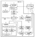
図1の例では、診断ロボットの構成要素である体型把握部3、触診ポイント設定部4、押し当て部5、反応観測部6、患部認定部7及び患部情報登録部8が専用のハードウェア(例えば、CPUなどのICが搭載されている半導体集積回路基板)から構成されているものを想定しているが、診断ロボットがコンピュータから構成されている場合、体型把握部3、触診ポイント設定部4、押し当て部5、反応観測部6、患部認定部7及び患部情報登録部8の処理内容(体型把握処理手順、触診ポイント設定処理手順、押し当て処理手順、反応観測処理手順、患部認定処理手順、患部情報登録処理手順)が記述されている制御プログラムをメモリに格納し、コンピュータのCPUが当該メモリに格納されている制御プログラムを実行するようにしてもよい。 In the example of FIG. 1, the body
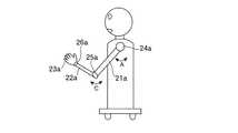
図2はこの発明の実施の形態1による診断ロボットを示す正面図であり、図3はこの発明の実施の形態1による診断ロボットを示す側面図である。
図2及び図3では、手のひら又は指を患者である子供に押し当てて、患部を探し当てる診断ロボットの例を示している。
図2及び図3において、診断ロボットの上腕部21a,21bは一端が可動自在に肩関節部24a,24bに取り付けられており、下腕部22a,22bは一端が可動自在に肘関節部25a,25bに取り付けられている。
また、診断ロボットの指23a,23bは一端が可動自在に手首関節部26a,26bに取り付けられている。2 is a front view showing the diagnostic robot according to the first embodiment of the present invention, and FIG. 3 is a side view showing the diagnostic robot according to the first embodiment of the present invention.
FIG. 2 and FIG. 3 show examples of a diagnostic robot that presses the palm or finger against a child who is a patient to find the affected area.
2 and 3, the
Further,
肩関節部24a,24bは押し当て部5の指示の下、例えば、上腕部21a,21bを矢印A方向に回転させるアクチュエータや、上腕部21a,21bを矢印B方向にスイングさせるアクチュエータなどからなる機械要素である。
肘関節部25a,25bは押し当て部5の指示の下、例えば、下腕部22a,22bを矢印C方向に回転させるアクチュエータなどからなる機械要素である。
手首関節部26a,26bは押し当て部5の指示の下、例えば、指23a,23bを上げたり下げたりさせるアクチュエータなどからなる機械要素である。
なお、診断ロボットの目27aには体型把握部3のカメラ3aが搭載され、診断ロボットの目27bには反応観測部6のカメラ6aが搭載されている。
また、診断ロボットの口28にはスピーカ9が搭載されている。
図4はこの発明の実施の形態1による診断ロボットの制御方法を示すフローチャートである。The
The elbow
The wrist
In addition, the camera 3a of the body
A
FIG. 4 is a flowchart showing a diagnostic robot control method according to Embodiment 1 of the present invention.
次に動作について説明する。
例えば、病院の待合室において、診断ロボットを使用して、医師の診察に先立って患部を事前に把握するような状況下では、例えば、医療事務員や看護師が診断ロボットの患者情報入力受付部2を操作して、患者である子供の個人情報(例えば、氏名)を入力する(ステップST1)。
体型把握部3は、患者情報入力受付部2が患者である子供の個人情報の入力を受け付けると、その個人情報をキーにして、カルテ記録部1から子供の体型情報を収集し、その体型情報を参照して子供の体型を把握する(ステップST2)。
ここで、子供の体型情報は、子供の身長、体重、座高、胸囲、腹囲、腰囲などが示されている情報である。Next, the operation will be described.
For example, in a situation where a diagnosis robot is used in a hospital waiting room to grasp an affected area in advance of a doctor's examination, for example, a medical clerk or nurse can receive a patient information
When the patient information
Here, the child's body type information is information indicating a child's height, weight, sitting height, chest circumference, abdominal circumference, waist circumference, and the like.
体型把握部3は、子供の個人情報がカルテ記録部1に登録されておらず、カルテ記録部1から子供の体型情報を収集することができない場合や、患者情報入力受付部2を操作して、患者である子供の個人情報を入力することができない場合(例えば、子供だけが自宅にいるような状況下では、個人情報を入力することができないものと考えられる)には、内蔵しているカメラ3aを用いて、患者である子供を撮影し、子供の映像を解析して体型を把握する。即ち、映像を解析して、子供の身長、座高、胸囲や腹囲などを測定する。
なお、カメラ3aが子供を撮影する際、カメラ3aから子供までの距離を測定すれば、その距離と映像中の子供の大きさとを比較すれば、子供の身長や座高などを計算することができる。The body
When the camera 3a captures a child, if the distance from the camera 3a to the child is measured, the height and sitting height of the child can be calculated by comparing the distance with the size of the child in the video. .
ただし、体型把握部3は、カメラ3aが子供を撮影して、子供の体型を把握する際、子供が直立しておらず、例えば、うずくまっているような状況下では、子供の映像を解析しても、体型を把握することができないので、例えば、起き上がって直立の姿勢をとるように指示するメッセージをスピーカ9から音声出力する。
言うまでもないが、“直立の姿勢”はあくまでも一例に過ぎず、例えば、仰向けで寝る姿勢や、椅子の腰掛ける姿勢でもよい。However, when the camera 3a captures the child and grasps the child's body shape, the body
Needless to say, the “upright posture” is merely an example, and for example, a posture of sleeping on the back or a posture of sitting on a chair may be used.
触診ポイント設定部4は、体型把握部3が子供の体型を把握すると、子供の体型に応じてN箇所の触診ポイントP1〜PNを設定する(ステップST3)。
例えば、子供の胴体の中から患部を探し当てる場合、図5に示すように、子供の座高と、胸囲又は腹囲とを基準にして、縦方向と横方向に等間隔に触診ポイントP1〜PNを設定する。
図5では、縦方向に5ポイント、横方向に6ポイントを設定する例を示している。ただし、これはあくまでも一例であり、縦方向に6ポイント以上、横方向に7ポイント以上を設定するようにしてもよい。When the body
For example, when searching for an affected part from the torso of a child, as shown in FIG. 5, palpation points P1 to PN at equal intervals in the vertical and horizontal directions based on the child's sitting height and chest or abdominal circumference. Set.
FIG. 5 shows an example in which 5 points are set in the vertical direction and 6 points are set in the horizontal direction. However, this is only an example, and 6 or more points in the vertical direction and 7 or more points in the horizontal direction may be set.
押し当て部5は、触診ポイント設定部4が触診ポイントP1〜PNを設定すると、例えば、ロボットの指23aを触診用部材として使用する設定がなされている場合、肩関節部24a,肘関節部25a及び手首関節部26aを制御して、上腕部21a,下腕部22a及び指23aを駆動することにより、ロボットの指23aを触診ポイントP1まで移動し、その触診ポイントP1にロボットの指23aを押し当てるようにする(ステップST4)。When the palpation
反応観測部6は、押し当て部5がロボットの指23aを触診ポイントP1に押し当てているとき、ユーザの反応を観測する(ステップST5)。
即ち、反応観測部6のカメラ6aは、押し当て部5がロボットの指23aを触診ポイントP1に押し当てているとき、ユーザを撮影し、ユーザの映像を画像解析部6bに出力する。
反応観測部6の画像解析部6bは、カメラ6aからユーザの映像を受けると、ユーザの映像の変化量C1を解析し、その変化量C1をユーザの反応の観測量としてメモリ6cに格納する。
例えば、カメラ6aがユーザを時系列に2回撮影し、最新の映像と前回の映像とを比較して、両映像のずれ量を変化量C1として計測する。
That is, the
Storing the
For example, the
押し当て部5は、反応観測部6が触診ポイントP1におけるユーザの反応を観測すると、再度、肩関節部24a,肘関節部25a及び手首関節部26aを制御して、上腕部21a,下腕部22a及び指23aを駆動することにより、ロボットの指23aを触診ポイントP2まで移動し、その触診ポイントP2にロボットの指23aを押し当てるようにする(ステップST4)。
反応観測部6は、押し当て部5がロボットの指23aを触診ポイントP2に押し当てているとき、ユーザの映像の変化量C2を解析し、その変化量C2をユーザの反応の観測量としてメモリ6cに格納する(ステップST5)。
押し当て部5及び反応観測部6は、N箇所の触診ポイントP1〜PNにおけるユーザの反応の観測が完了するまで、ステップST4,ST5の処理を繰り返し実施する(ステップST6)。The
When the
The
患部認定部7は、反応観測部6が触診ポイントP1〜PNにおけるユーザの反応を観測すると、その触診ポイントP1〜PNにおけるユーザの反応の観測量C1〜CNを比較して、その触診ポイントP1〜PNの中で観測量C1〜CNが最も大きい触診ポイントPmaxを特定し、その触診ポイントPmaxを患部に認定する(ステップST7)
患部情報登録部8は、患部認定部7が患部に認定すると、その患部の位置を示す情報(触診ポイントPmaxの位置)をカルテ記録部1に登録する(ステップST8)。
これにより、例えば、家族や医師などが携帯端末やパソコンなどを使用して、カルテ記録部1をアクセスすれば、患者である子供の患部を把握することができる。When the
When the affected
Accordingly, for example, if a family member, a doctor, or the like accesses the medical record recording unit 1 using a mobile terminal or a personal computer, the affected part of the child who is a patient can be grasped.
以上で明らかなように、この実施の形態1によれば、押し当て部5により触診用部材であるロボットの指23aが押し当てられている状態にあるときのユーザの反応を観測する反応観測部6を設け、患部認定部7が触診ポイント設定部4により設定された触診ポイントP1〜PNの中で、反応観測部6により観測されたユーザの反応が最も大きい触診ポイントPmaxを特定して、その触診ポイントPmaxを患部に認定するように構成したので、例えば、会話を十分に行うことができない子供の患部を探し当てることができる効果を奏する。As apparent from the above, according to the first embodiment, the reaction observation unit that observes the reaction of the user when the
また、この実施の形態1によれば、押し当て部5により触診用部材であるロボットの指23aが押し当てられている状態にあるときのユーザを撮影し、ユーザの映像の変化量C1〜CNをユーザの反応として観測するように構成したので、ユーザが会話を十分に行うことができない場合でも、痛い部位を調べることができる効果を奏する。
さらに、この実施の形態1によれば、患部情報登録部8が患部認定部7により認定された患部の位置を示す情報をカルテ記録部1に登録するように構成したので、例えば、家族や医師などが本格的な治療を行う前に、患部を把握することができる効果を奏する。Also, according to the first embodiment, the user is photographed when the
Further, according to the first embodiment, since the affected part
なお、この実施の形態1では、ロボットの指23aが触診用部材として使用されるように設定されているものについて示したが、これはあくまでも一例であり、例えば、ロボットの指23b、ロボットの手のひら、ロボットの肘などを触診用部材として使用するように設定してもよい。
触診用部材の設定は、例えば、図示せぬ設定用スイッチがロボットに搭載されていれば実現することができる。In the first embodiment, the
The setting of the palpation member can be realized, for example, if a setting switch (not shown) is mounted on the robot.
この実施の形態1では、子供の患部を認定するものについて示したが、言うまでもないが、子供以外のユーザの患部を認定するようにしてもよい。 In this Embodiment 1, although it showed about what certifies the affected part of a child, it cannot be overemphasized, and you may make it certify the affected part of users other than a child.
実施の形態2.
図6はこの発明の実施の形態2による診断ロボットの内部を示す構成図であり、図において、図1と同一符号は同一または相当部分を示すので説明を省略する。
反応観測部6のマイク6dは押し当て部5によりロボットの手が押し当てられている状態にあるときのユーザの声を集音する。
反応観測部6の音量観測部6eはマイク6dにより集音されたユーザの声の音量V1〜VNをユーザの反応の観測量としてメモリ6cに格納する。
6 is a block diagram showing the inside of a diagnostic robot according to
The
The sound
上記実施の形態1では、反応観測部6のカメラ6aが、押し当て部5によりロボットの指23aが触診ポイントP1〜PNに押し当てられているとき、ユーザを撮影してユーザの映像を画像解析部6bに出力し、画像解析部6bがユーザの映像の変化量C1〜CNを解析し、その変化量C1〜CNをユーザの反応の観測量としてメモリ6cに格納するものについて示したが、以下に示すように、ユーザの声の音量V1〜VNをユーザの反応の観測量としてメモリ6cに格納するようにしてもよい。In the first embodiment, when the
即ち、反応観測部6のマイク6dは、押し当て部5がロボットの指23aを触診ポイントP1に押し当てているとき、ユーザの声を集音して、その音声信号を音量観測部6eに出力する。
反応観測部6の音量観測部6eは、マイク6dから音声信号を受けると、その音声信号の信号レベルを示す音量V1をユーザの反応の観測量としてメモリ6cに格納する。
ここでは、ロボットの指23aが触診ポイントP1に押し当てている状態のときのユーザの反応を観測するものについて示したが、反応観測部6は、上記実施の形態1と同様に、すべての触診ポイントP1〜PNでのユーザの反応を観測する。In other words, the
When receiving a sound signal from the
Here, as mentioned above. Observing the response of the user in the state where the
患部認定部7は、反応観測部6が触診ポイントP1〜PNにおけるユーザの反応を観測すると、その触診ポイントP1〜PNにおけるユーザの反応の観測量V1〜VNを比較して、その触診ポイントP1〜PNの中で観測量V1〜VNが最も大きい触診ポイントPmaxを特定し、その触診ポイントPmaxを患部に認定する。When the
以上で明らかなように、この実施の形態2によれば、押し当て部5により触診用部材であるロボットの指23aが押し当てられている状態にあるときのユーザの声を集音し、その声の音量V1〜VNをユーザの反応として観測するように構成したので、ユーザが会話を十分に行うことができない場合でも、痛い部位を調べることができる効果を奏する。As apparent from the above, according to the second embodiment, the voice of the user when the
実施の形態3.
図7はこの発明の実施の形態3による診断ロボットの内部を示す構成図である。
上記実施の形態1では、反応観測部6がユーザの映像の変化量C1〜CNをユーザの反応の観測量としてメモリ6cに格納し、上記実施の形態2では、ユーザの声の音量V1〜VNをユーザの反応の観測量としてメモリ6cに格納するものについて示したが、ユーザの映像の変化量C1〜CNとユーザの声の音量V1〜VNをポイントに換算し、そのポイントの合計を観測量としてメモリ6cに格納するようにしてもよい。
FIG. 7 is a block diagram showing the inside of the diagnostic robot according to the third embodiment of the present invention.
In the first embodiment, the
具体的には、以下の通りである。
反応観測部6の画像解析部6bは、上記実施の形態1と同様にして、ユーザの映像の変化量Cnを解析すると、その変化量Cnを閾値Cref1,Cref2と比較し(Cref1>Cref2)、下記に示すように、その比較結果に応じて、その変化量Cnに関するポイントCPnを決定する。
変化量Cn ポイントCPn
Cn≧Cref1 5
Cref1>Cn≧Cref2 3
Cref2>Cn 1Specifically, it is as follows.
When the
Change amount Cn point CPn
Cn ≧ Cref1 5
Cref1 > Cn ≧ Cref2 3
Cref2 > Cn 1
反応観測部6の音量観測部6eは、上記実施の形態2と同様にして、ユーザの声の音量Vnを観測すると、下記に示すように、その音量Vnのレベルに応じて、その音量Vnに関するポイントVPnを決定する。
音量Vn ポイントVPn
60dB以上 20
59dB〜50dB 15
49dB〜40dB 11
39dB〜30dB 7
29dB〜20dB 3
19dB〜10dB 2
9dB〜 0dB 1When the
Volume Vn point VPn
60 dB or more 20
59dB ~
49dB ~
39 dB to 30
29dB ~
19dB-
9 dB to 0 dB 1
したがって、反応観測部6のメモリ6cには、各触診ポイントPnについて、画像解析部6bにより決定されたポイントCPnと、音量観測部6eにより決定されたポイントVPnとの合計Tn(=CPn+VPn)がユーザの反応の観測量として格納される。
患部認定部7は、反応観測部6が触診ポイントP1〜PNにおけるユーザの反応を観測すると、その触診ポイントP1〜PNにおけるユーザの反応の観測量T1〜TNを比較して、その触診ポイントP1〜PNの中で観測量T1〜TNが最も大きい触診ポイントPmaxを特定し、その触診ポイントPmaxを患部に認定する。
この実施の形態3によれば、ユーザの変化量と音声の双方を観測しているので、上記実施の形態1,2よりも、ユーザの反応を正確に捉えることができる効果を奏する。Accordingly, the
When the
According to the third embodiment, since both the user's change amount and the voice are observed, there is an effect that the user's reaction can be accurately captured as compared with the first and second embodiments.
なお、上記実施の形態1〜3では、触診ポイント設定部4が触診ポイントP1〜PNを設定すると、押し当て部5が触診ポイントP1〜PNにロボットの手を押し当てるものについて示したが、押し当て部5が触診ポイントP1〜PNにロボットの手を押し当てる際、例えば「ここが痛いですか?」などの音声出力を行う問い掛けを実施するようにしてもよい。音声出力は、例えば、押し当て部5がスピーカを内蔵し、内蔵のスピーカを通じて出力してもよい。これにより、触診が行われている旨をユーザが容易に理解することができる。
このように、押し当て部5が「ここが痛いですか?」などの問い掛けを実施する場合、患部認定部7は、この問い掛けに対して、ユーザが例えば「うなずく」などの動作を行えば、あるいは、「痛い」などの音声を発すれば、現在、ロボットの手が押し当てている触診ポイントP1〜PNを患部に認定することができる。
なお、ユーザの「うなずく」などの動作は、例えば、患部認定部7がカメラや画像解析部を実装すれば検知することができる。また、ユーザの「痛い」などの音声は、例えば、患部認定部7がマイクや音声認識処理部を実装すれば検知することができる。In the first to third embodiments, when the palpation
As described above, when the
The user's operation such as “nodding” can be detected, for example, if the affected
実施の形態4.
図8はこの発明の実施の形態4による診断ロボットの内部を示す構成図であり、図において、図7と同一符号は同一または相当部分を示すので説明を省略する。
バイタル測定部10は例えば触診用部材であるロボットの指23aに取り付けられているセンサー(例えば、血圧計、体温計、硬度計、心音計、肌色検査器、エコー検査器など)であり、例えば、押し当て部5によりロボットの手が触診ポイントP1〜PNに押し当てられているとき、あるいは、患部認定部7により患部が認定されたとき、子供のバイタルを測定する処理を実施する。ただし、バイタルの測定は、必ずしも反応観測部6が反応を観測している最中である必要はない。
バイタル情報登録部11はバイタル測定部10により測定されたバイタルを示す情報をカルテ記録部1に登録する処理を実施する。
なお、バイタル測定部10及びバイタル情報登録部11からバイタル情報登録手段が構成されている。
FIG. 8 is a block diagram showing the inside of a diagnostic robot according to
The
The vital
The
上記実施の形態1〜3では、患部情報登録部8が患部認定部7により認定された患部の位置を示す情報(触診ポイントPmaxの位置)をカルテ記録部1に登録するものについて示したが、さらに、患者である子供のバイタルを示す情報をカルテ記録部1に登録するようにしてもよい。
即ち、バイタル測定部10は、例えば、押し当て部5によりロボットの手が触診ポイントP1〜PNに押し当てられているとき、あるいは、患部認定部7により患部が認定されたとき、子供のバイタルを測定する。
バイタル情報登録部11は、バイタル測定部10が子供のバイタルを測定すると、そのバイタルを示す情報をカルテ記録部1に登録する。In the first to third embodiments, the diseased part
In other words, the
When the
以上で明らかなように、この実施の形態4によれば、患者である子供のバイタルを測定し、そのバイタルを示す情報をカルテ記録部1に登録するように構成したので、例えば、家族や医師などが患者の状態を容易に把握することができる効果を奏する。 As apparent from the above, according to the fourth embodiment, since the patient's vitality is measured and information indicating the vital is registered in the medical record recording unit 1, for example, a family member or a doctor Etc. have the effect of easily grasping the patient's condition.
実施の形態5.
図9はこの発明の実施の形態5による診断ロボットの内部を示す構成図であり、図において、図8と同一符号は同一または相当部分を示すので説明を省略する。
音声出力部12は例えば音声合成装置から構成されており、患者である子供に痛い部位を手で触れることを促すメッセージを音声出力する処理を実施する。なお、音声出力部12は音声出力手段を構成している。
映像登録部13はカメラ13aを実装しており、音声出力部12から音声が出力されたのち、患者である子供が触れている手の位置を撮影して、手の位置の映像をカルテ記録部1に登録する処理を実施する。なお、映像登録部13は映像登録手段を構成している。
9 is a block diagram showing the inside of a diagnostic robot according to
The
The
上記実施の形態1〜4では、患部認定部7が反応観測部6により観測された子供の反応に基づいて患部を認定するものについて示したが、子供の状態によっては、反応が顕著に現れず、患部を正確に認定することができない場合がある。
そこで、この実施の形態5では、患部認定部7における患部の認定を補助するために、音声出力部12と映像登録部13を実装するようにしている。
具体的には、以下の通りである。In the first to fourth embodiments described above, the diseased
Therefore, in the fifth embodiment, the
Specifically, it is as follows.
音声出力部12は、患者である子供に痛い部位を手で触れることを促すメッセージを音声出力する。これにより、患者である子供が、自分の手で患部を触れることが想定される。
映像登録部13は、音声出力部12から音声が出力されたのち、実装しているカメラ13aを使用して、患者である子供が触れている手の位置を撮影し、手の位置の映像をカルテ記録部1に登録する。
これにより、家族や医師が映像中の手の位置を見れば、患部を把握することができる。The
After the sound is output from the
Thereby, if a family and a doctor look at the position of the hand in a picture, it can grasp an affected part.
以上で明らかなように、この実施の形態5によれば、患者である子供に痛い部位を手で触れることを促すメッセージを音声出力する音声出力部12と、その音声出力部12から音声が出力されたのち、ユーザが触れている手の位置を撮影して、手の位置の映像をカルテ記録部1に登録する映像登録部13とを設けるように構成したので、上記実施の形態1〜4よりも正確に患部を認定することができる効果を奏する。 As is apparent from the above, according to the fifth embodiment, the
実施の形態6.
上記実施の形態1〜5では、患部認定部7により認定された患部の位置を示す情報(触診ポイントPmaxの位置)をカルテ記録部1に登録するものについて示したが、患部認定部7が患部を認定すると、患部を認定した旨を例えば医師の携帯端末などに直接通知するようにしてもよい。
その際、医師などが、診断ロボットを遠隔操作できる仕組みを実装するようにしてもよい。例えば、診断ロボットが心臓マッサージ用のAEDを患者に貼り付ける処置を行う遠隔操作などが考えられる。
また、患部認定部7が患者の患部に、患部である旨を示すマークをつけるようにしてもよい。
また、患部認定部7が患部の対処法や受診診療科を案内するようにしてもよい。
In the said Embodiment 1-5, although shown about what registers the information (position of palpation pointPmax ) which shows the position of the affected part recognized by the affected
At this time, a mechanism that allows a doctor or the like to remotely operate the diagnostic robot may be implemented. For example, a remote operation in which a diagnostic robot performs a procedure of attaching an AED for cardiac massage to a patient can be considered.
Alternatively, the affected
Further, the affected
なお、上記実施の形態1〜6では、複数のカメラ(例えば、カメラ3a,6a,13a)が実装されているものについて示したが、診断ロボットには1台のカメラを実装し、1台のカメラがカメラ3a,6a,13aの機能を兼ねるようにしてもよい。 In the first to sixth embodiments, a case where a plurality of cameras (for example, the
1 カルテ記録部(閲覧可能な記録媒体)
2 患者情報入力受付部(触診ポイント設定手段)
3 体型把握部(触診ポイント設定手段)
3a カメラ
4 触診ポイント設定部(触診ポイント設定手段)
5 押し当て部(押し当て手段)
6 反応観測部(反応観測手段)
6a カメラ
6b 画像解析部
6c メモリ
6d マイク
6e 音量観測部
7 患部認定部(患部認定手段)
8 患部情報登録部(患部情報登録手段)
9 スピーカ
10 バイタル測定部(バイタル情報登録手段)
11 バイタル情報登録部(バイタル情報登録手段)
12 音声出力部(音声出力手段)
13 映像登録部(映像登録手段)
13a カメラ
21a,21b 上腕部
22a,22b 下腕部
23a,23b 指(触診用部材)
24a,24b 肩関節部
25a,25b 肘関節部
26a,26b 手首関節部
27a,27b 目
28 口1 Medical record recording section (recordable recording media)
2 Patient information input reception part (Palpation point setting means)
3 Body shape grasping part (Palpation point setting means)
5 Pushing part (Pushing means)
6 Reaction observation section (reaction observation means)
8 affected area information registration section (affected area information registration means)
9
11 Vital information registration department (Vital information registration means)
12 Audio output unit (Audio output means)
13 Video registration unit (Video registration means)
24a, 24b shoulder
Claims (8)
Translated fromJapanesePriority Applications (1)
| Application Number | Priority Date | Filing Date | Title |
|---|---|---|---|
| JP2007002741AJP2008167866A (en) | 2007-01-10 | 2007-01-10 | Diagnostic robot, and control method and control program of diagnostic robot |
Applications Claiming Priority (1)
| Application Number | Priority Date | Filing Date | Title |
|---|---|---|---|
| JP2007002741AJP2008167866A (en) | 2007-01-10 | 2007-01-10 | Diagnostic robot, and control method and control program of diagnostic robot |
Publications (1)
| Publication Number | Publication Date |
|---|---|
| JP2008167866Atrue JP2008167866A (en) | 2008-07-24 |
Family
ID=39696512
Family Applications (1)
| Application Number | Title | Priority Date | Filing Date |
|---|---|---|---|
| JP2007002741APendingJP2008167866A (en) | 2007-01-10 | 2007-01-10 | Diagnostic robot, and control method and control program of diagnostic robot |
Country Status (1)
| Country | Link |
|---|---|
| JP (1) | JP2008167866A (en) |
Cited By (3)
| Publication number | Priority date | Publication date | Assignee | Title |
|---|---|---|---|---|
| CN109641357A (en)* | 2016-08-24 | 2019-04-16 | 川崎重工业株式会社 | The remote supervision system of robot |
| JP2020121353A (en)* | 2019-01-29 | 2020-08-13 | 新東工業株式会社 | robot |
| CN113598714A (en)* | 2021-08-17 | 2021-11-05 | 深圳市罗湖医院集团 | Automatic palpation method, device, electronic equipment and storage medium |
- 2007
- 2007-01-10JPJP2007002741Apatent/JP2008167866A/enactivePending
Cited By (4)
| Publication number | Priority date | Publication date | Assignee | Title |
|---|---|---|---|---|
| CN109641357A (en)* | 2016-08-24 | 2019-04-16 | 川崎重工业株式会社 | The remote supervision system of robot |
| CN109641357B (en)* | 2016-08-24 | 2022-10-14 | 川崎重工业株式会社 | Remote Monitoring System for Robots |
| JP2020121353A (en)* | 2019-01-29 | 2020-08-13 | 新東工業株式会社 | robot |
| CN113598714A (en)* | 2021-08-17 | 2021-11-05 | 深圳市罗湖医院集团 | Automatic palpation method, device, electronic equipment and storage medium |
Similar Documents
| Publication | Publication Date | Title |
|---|---|---|
| JP6878628B2 (en) | Systems, methods, and computer program products for physiological monitoring | |
| US10839956B2 (en) | Universal device and method to integrate diagnostic testing into treatment in real-time | |
| TW480168B (en) | Multi-modal cardiac diagnostic decision support system | |
| WO2013089072A1 (en) | Information management device, information management method, information management system, stethoscope, information management program, measurement system, control program and recording medium | |
| US12183457B2 (en) | Diagnostic device for remote consultations and telemedicine | |
| US20170007126A1 (en) | System for conducting a remote physical examination | |
| US8200277B2 (en) | Mobile phone with a stethoscope | |
| CN101015450A (en) | China electronic pulse feeling device | |
| US20090203986A1 (en) | Medical data collection device | |
| JP2020022696A (en) | Biological information measurement device, biological information system | |
| JP2002052022A (en) | Stethoscope mouth | |
| CN109330581A (en) | A wearable pulse information collection device | |
| KR20190058858A (en) | Method for providing diagnostic information on cardiovascular diseases using a smart device and heart sound application for the same | |
| CN104427942A (en) | Measurement aid, measurement aid method, control program, and recording medium | |
| WO2019000909A1 (en) | Telemedical device, information acquisition device, and telemedical system and method | |
| US20250064424A1 (en) | Electronic stethoscope and diagnostic algorithm | |
| US20220151582A1 (en) | System and method for assessing pulmonary health | |
| US20060281975A1 (en) | Home health care interacting instrument | |
| JP2008167866A (en) | Diagnostic robot, and control method and control program of diagnostic robot | |
| US20040225476A1 (en) | Inspection apparatus for diagnosis | |
| US20130123646A1 (en) | Method and electronic device for remote diagnosis | |
| TWM446374U (en) | Coughs recording device | |
| US9076310B2 (en) | Method and electronic device for remote diagnosis | |
| JP2024534050A (en) | Methods for non-invasive capture of the temporal evolution of the state of tissue structures - Patents.com | |
| JP2019088730A (en) | Ultrasonic probe, ultrasonic measurement system |